JP5475474B2 - Microreplication tools and patterns using laser-induced hot embossing - Google Patents
Microreplication tools and patterns using laser-induced hot embossing Download PDFInfo
- Publication number
- JP5475474B2 JP5475474B2 JP2009554625A JP2009554625A JP5475474B2 JP 5475474 B2 JP5475474 B2 JP 5475474B2 JP 2009554625 A JP2009554625 A JP 2009554625A JP 2009554625 A JP2009554625 A JP 2009554625A JP 5475474 B2 JP5475474 B2 JP 5475474B2
- Authority
- JP
- Japan
- Prior art keywords
- film
- lite
- tool
- pattern
- layer
- Prior art date
- Legal status (The legal status is an assumption and is not a legal conclusion. Google has not performed a legal analysis and makes no representation as to the accuracy of the status listed.)
- Expired - Fee Related
Links
Images


Classifications
-
- B—PERFORMING OPERATIONS; TRANSPORTING
- B29—WORKING OF PLASTICS; WORKING OF SUBSTANCES IN A PLASTIC STATE IN GENERAL
- B29C—SHAPING OR JOINING OF PLASTICS; SHAPING OF MATERIAL IN A PLASTIC STATE, NOT OTHERWISE PROVIDED FOR; AFTER-TREATMENT OF THE SHAPED PRODUCTS, e.g. REPAIRING
- B29C59/00—Surface shaping of articles, e.g. embossing; Apparatus therefor
- B29C59/02—Surface shaping of articles, e.g. embossing; Apparatus therefor by mechanical means, e.g. pressing
- B29C59/022—Surface shaping of articles, e.g. embossing; Apparatus therefor by mechanical means, e.g. pressing characterised by the disposition or the configuration, e.g. dimensions, of the embossments or the shaping tools therefor
-
- B—PERFORMING OPERATIONS; TRANSPORTING
- B29—WORKING OF PLASTICS; WORKING OF SUBSTANCES IN A PLASTIC STATE IN GENERAL
- B29C—SHAPING OR JOINING OF PLASTICS; SHAPING OF MATERIAL IN A PLASTIC STATE, NOT OTHERWISE PROVIDED FOR; AFTER-TREATMENT OF THE SHAPED PRODUCTS, e.g. REPAIRING
- B29C59/00—Surface shaping of articles, e.g. embossing; Apparatus therefor
- B29C59/02—Surface shaping of articles, e.g. embossing; Apparatus therefor by mechanical means, e.g. pressing
-
- B—PERFORMING OPERATIONS; TRANSPORTING
- B23—MACHINE TOOLS; METAL-WORKING NOT OTHERWISE PROVIDED FOR
- B23B—TURNING; BORING
- B23B27/00—Tools for turning or boring machines; Tools of a similar kind in general; Accessories therefor
- B23B27/14—Cutting tools of which the bits or tips or cutting inserts are of special material
-
- B—PERFORMING OPERATIONS; TRANSPORTING
- B26—HAND CUTTING TOOLS; CUTTING; SEVERING
- B26D—CUTTING; DETAILS COMMON TO MACHINES FOR PERFORATING, PUNCHING, CUTTING-OUT, STAMPING-OUT OR SEVERING
- B26D1/00—Cutting through work characterised by the nature or movement of the cutting member or particular materials not otherwise provided for; Apparatus or machines therefor; Cutting members therefor
-
- B—PERFORMING OPERATIONS; TRANSPORTING
- B29—WORKING OF PLASTICS; WORKING OF SUBSTANCES IN A PLASTIC STATE IN GENERAL
- B29D—PRODUCING PARTICULAR ARTICLES FROM PLASTICS OR FROM SUBSTANCES IN A PLASTIC STATE
- B29D7/00—Producing flat articles, e.g. films or sheets
- B29D7/01—Films or sheets
-
- B—PERFORMING OPERATIONS; TRANSPORTING
- B29—WORKING OF PLASTICS; WORKING OF SUBSTANCES IN A PLASTIC STATE IN GENERAL
- B29C—SHAPING OR JOINING OF PLASTICS; SHAPING OF MATERIAL IN A PLASTIC STATE, NOT OTHERWISE PROVIDED FOR; AFTER-TREATMENT OF THE SHAPED PRODUCTS, e.g. REPAIRING
- B29C35/00—Heating, cooling or curing, e.g. crosslinking or vulcanising; Apparatus therefor
- B29C35/02—Heating or curing, e.g. crosslinking or vulcanizing during moulding, e.g. in a mould
- B29C35/08—Heating or curing, e.g. crosslinking or vulcanizing during moulding, e.g. in a mould by wave energy or particle radiation
- B29C35/0805—Heating or curing, e.g. crosslinking or vulcanizing during moulding, e.g. in a mould by wave energy or particle radiation using electromagnetic radiation
- B29C2035/0822—Heating or curing, e.g. crosslinking or vulcanizing during moulding, e.g. in a mould by wave energy or particle radiation using electromagnetic radiation using IR radiation
-
- B—PERFORMING OPERATIONS; TRANSPORTING
- B29—WORKING OF PLASTICS; WORKING OF SUBSTANCES IN A PLASTIC STATE IN GENERAL
- B29C—SHAPING OR JOINING OF PLASTICS; SHAPING OF MATERIAL IN A PLASTIC STATE, NOT OTHERWISE PROVIDED FOR; AFTER-TREATMENT OF THE SHAPED PRODUCTS, e.g. REPAIRING
- B29C35/00—Heating, cooling or curing, e.g. crosslinking or vulcanising; Apparatus therefor
- B29C35/02—Heating or curing, e.g. crosslinking or vulcanizing during moulding, e.g. in a mould
- B29C35/08—Heating or curing, e.g. crosslinking or vulcanizing during moulding, e.g. in a mould by wave energy or particle radiation
- B29C35/0805—Heating or curing, e.g. crosslinking or vulcanizing during moulding, e.g. in a mould by wave energy or particle radiation using electromagnetic radiation
- B29C2035/0827—Heating or curing, e.g. crosslinking or vulcanizing during moulding, e.g. in a mould by wave energy or particle radiation using electromagnetic radiation using UV radiation
-
- B—PERFORMING OPERATIONS; TRANSPORTING
- B29—WORKING OF PLASTICS; WORKING OF SUBSTANCES IN A PLASTIC STATE IN GENERAL
- B29C—SHAPING OR JOINING OF PLASTICS; SHAPING OF MATERIAL IN A PLASTIC STATE, NOT OTHERWISE PROVIDED FOR; AFTER-TREATMENT OF THE SHAPED PRODUCTS, e.g. REPAIRING
- B29C35/00—Heating, cooling or curing, e.g. crosslinking or vulcanising; Apparatus therefor
- B29C35/02—Heating or curing, e.g. crosslinking or vulcanizing during moulding, e.g. in a mould
- B29C35/08—Heating or curing, e.g. crosslinking or vulcanizing during moulding, e.g. in a mould by wave energy or particle radiation
- B29C35/0805—Heating or curing, e.g. crosslinking or vulcanizing during moulding, e.g. in a mould by wave energy or particle radiation using electromagnetic radiation
- B29C2035/0838—Heating or curing, e.g. crosslinking or vulcanizing during moulding, e.g. in a mould by wave energy or particle radiation using electromagnetic radiation using laser
-
- B—PERFORMING OPERATIONS; TRANSPORTING
- B29—WORKING OF PLASTICS; WORKING OF SUBSTANCES IN A PLASTIC STATE IN GENERAL
- B29C—SHAPING OR JOINING OF PLASTICS; SHAPING OF MATERIAL IN A PLASTIC STATE, NOT OTHERWISE PROVIDED FOR; AFTER-TREATMENT OF THE SHAPED PRODUCTS, e.g. REPAIRING
- B29C59/00—Surface shaping of articles, e.g. embossing; Apparatus therefor
- B29C59/02—Surface shaping of articles, e.g. embossing; Apparatus therefor by mechanical means, e.g. pressing
- B29C59/022—Surface shaping of articles, e.g. embossing; Apparatus therefor by mechanical means, e.g. pressing characterised by the disposition or the configuration, e.g. dimensions, of the embossments or the shaping tools therefor
- B29C2059/023—Microembossing
-
- B—PERFORMING OPERATIONS; TRANSPORTING
- B29—WORKING OF PLASTICS; WORKING OF SUBSTANCES IN A PLASTIC STATE IN GENERAL
- B29C—SHAPING OR JOINING OF PLASTICS; SHAPING OF MATERIAL IN A PLASTIC STATE, NOT OTHERWISE PROVIDED FOR; AFTER-TREATMENT OF THE SHAPED PRODUCTS, e.g. REPAIRING
- B29C35/00—Heating, cooling or curing, e.g. crosslinking or vulcanising; Apparatus therefor
- B29C35/02—Heating or curing, e.g. crosslinking or vulcanizing during moulding, e.g. in a mould
- B29C35/0272—Heating or curing, e.g. crosslinking or vulcanizing during moulding, e.g. in a mould using lost heating elements, i.e. heating means incorporated and remaining in the formed article
-
- Y—GENERAL TAGGING OF NEW TECHNOLOGICAL DEVELOPMENTS; GENERAL TAGGING OF CROSS-SECTIONAL TECHNOLOGIES SPANNING OVER SEVERAL SECTIONS OF THE IPC; TECHNICAL SUBJECTS COVERED BY FORMER USPC CROSS-REFERENCE ART COLLECTIONS [XRACs] AND DIGESTS
- Y10—TECHNICAL SUBJECTS COVERED BY FORMER USPC
- Y10T—TECHNICAL SUBJECTS COVERED BY FORMER US CLASSIFICATION
- Y10T156/00—Adhesive bonding and miscellaneous chemical manufacture
- Y10T156/10—Methods of surface bonding and/or assembly therefor
- Y10T156/1002—Methods of surface bonding and/or assembly therefor with permanent bending or reshaping or surface deformation of self sustaining lamina
- Y10T156/1039—Surface deformation only of sandwich or lamina [e.g., embossed panels]
- Y10T156/1041—Subsequent to lamination
-
- Y—GENERAL TAGGING OF NEW TECHNOLOGICAL DEVELOPMENTS; GENERAL TAGGING OF CROSS-SECTIONAL TECHNOLOGIES SPANNING OVER SEVERAL SECTIONS OF THE IPC; TECHNICAL SUBJECTS COVERED BY FORMER USPC CROSS-REFERENCE ART COLLECTIONS [XRACs] AND DIGESTS
- Y10—TECHNICAL SUBJECTS COVERED BY FORMER USPC
- Y10T—TECHNICAL SUBJECTS COVERED BY FORMER US CLASSIFICATION
- Y10T428/00—Stock material or miscellaneous articles
- Y10T428/31504—Composite [nonstructural laminate]
- Y10T428/31678—Of metal
Description
本発明は、微細複製工具並びにそれらをレーザー誘起熱エンボス加工(LITE)フィルム及びレーザー誘起熱画像化(LITI)方法を使用して製造するための方法に関する。 The present invention relates to microreplication tools and methods for making them using laser induced thermal embossing (LITE) film and laser induced thermal imaging (LITI) methods.
微細複製工具のような多種多様なワークピースを創出するために、ダイヤモンドターニング及びプランジ放電加工のような機械加工技術を使用することができる。微細複製工具は、押出成形プロセス、射出成形プロセス、エンボス加工プロセス、鋳造プロセスなどのために一般的に使用されて、微細構造を創出する。微細構造化表面を有する物品は、光学フィルム、研磨フィルム、接着フィルム、自己嵌合輪郭を有する機械的締結具、又は相対的に小さい寸法、例えばおよそ1000マイクロメートル未満の寸法の微細複製形状を有するいかなる成形若しくは押出部品を含んでもよい。 Machining techniques such as diamond turning and plunge electric discharge machining can be used to create a wide variety of workpieces such as microreplicated tools. Microreplication tools are commonly used for extrusion processes, injection molding processes, embossing processes, casting processes, etc. to create microstructures. Articles with microstructured surfaces have optical films, abrasive films, adhesive films, mechanical fasteners with a self-fitting contour, or a microreplicated shape with relatively small dimensions, for example less than about 1000 micrometers Any molded or extruded part may be included.
微細構造化形状はまた、様々な他の方法により製造されることができる。例えば、マスター工具の構造は、生産用工具を形成するために、鋳造及び硬化プロセスにより、マスター工具から他の媒体上、例えばポリマー材料のベルト又はウェブに転写されることができ、生産用工具は次に微細構造を製造するために使用される。マスター工具を複写するために、電鋳法のような他の方法を使用することができる。工具を製造する他の技術には、化学エッチング、ビーズブラスティング、又は他の確率的表面改質技術が挙げられる。 The microstructured shape can also be produced by various other methods. For example, the structure of the master tool can be transferred from the master tool onto other media, such as a belt or web of polymer material, by a casting and curing process to form a production tool, It is then used to produce a microstructure. Other methods such as electroforming can be used to copy the master tool. Other techniques for manufacturing the tool include chemical etching, bead blasting, or other stochastic surface modification techniques.
本発明に従うLITEフィルムは、基材と基材にオーバーレイする光熱変換層とを含む。LITEフィルムの表面は、その上に選択的にエンボス加工された微細構造化表面を有することができる。 The LITE film according to the present invention includes a substrate and a photothermal conversion layer overlaying the substrate. The surface of the LITE film can have a microstructured surface selectively embossed thereon.
本発明に従う微細複製工具を製作する方法は、基材と基材にオーバーレイする光熱変換層とを含む、LITEフィルムを提供する工程と、光熱変換層が微細構造に接触した状態で、微細構造のパターンを含むマスター工具に、LITEフィルムをラミネートする工程と、LITEフィルムをパターンごとに画像化して、光熱変換層を選択的に露光する工程と、マスター工具を取り除いて、LITEフィルム上に、マスター工具の微細構造に対応する微細構造化パターンを製造する工程と、を含む。 A method for making a microreplication tool according to the present invention comprises providing a ITE film comprising a substrate and a photothermal conversion layer overlaid on the substrate, and the microstructure of the microstructure with the photothermal conversion layer in contact with the microstructure. A process of laminating a lite film on a master tool including a pattern, a process of imaging the lite film for each pattern and selectively exposing the light-to-heat conversion layer, and removing the master tool, the master tool on the lite film Manufacturing a microstructured pattern corresponding to the microstructure.
添付図面は本明細書に組み込まれ、その一部を構成するものであって、その記載と共に本発明の利点及び原理を説明する。
本発明の実施形態は、微細及びナノ複製プロセスのための複雑な工具を作り出すための方法を含む。方法は、精密レーザー露光及びLITEの態様を、従来の微細複製工具、例えば精密ダイヤモンド加工、フラットのエキシマレーザー加工(Excimer Laser Machining of Flats)(ELMoF)、フォトリソグラフィーによるパターニング、又は他の技術を使用して製造されるものと組み合わせることを伴う。LITEは、実質上いかなる微細複製工具表面、及び十分な熱安定性を有するLITEシート又はフィルムを使用しても実行され得る。フィルムは、微細複製工具にラミネートされ、次いで背後からレーザーで露光する。結果は、レーザー露光区域において微細複製工具のパターンに対応する3次元のエンボス加工されたパターンである。 Embodiments of the present invention include methods for creating complex tools for micro and nano replication processes. The method uses precision laser exposure and LITE aspects, using conventional fine replication tools such as precision diamond machining, Excimer Laser Machining of Flats (ELMoF), photolithography patterning, or other techniques Combined with what is manufactured. LITE can be performed using virtually any microreplicated tool surface and a LITE sheet or film that has sufficient thermal stability. The film is laminated to a microreplication tool and then exposed with a laser from behind. The result is a three-dimensional embossed pattern corresponding to the pattern of the microreplication tool in the laser exposure area.
LITEは、多くの異なる微細構造化フィルムを創出するために使用することができる。例えば、LITEは、単一のホログラフィックマスターを使用して、カスタマイズ可能なホログラフィックパターンをフィルム基材上に保安用用途に創出するため(例えば、運転免許証又はクレジットカード用ラミネート)の迅速な方法を提供することができる。LITEはまた、例えば、それらの微細構造化された光学要素に基づく様々な他の光学特性を有する微細構造化フィルムを創出するために使用されることができる。加えて、LITEは、異なるMS工具法(MS tooling methods)からの要素を1つのLITE工具に組み合わせる能力を提供する。 LITE can be used to create many different microstructured films. For example, LITE uses a single holographic master to quickly create a customizable holographic pattern on a film substrate for security applications (eg, driver's license or credit card laminate). A method can be provided. LITE can also be used, for example, to create microstructured films with various other optical properties based on their microstructured optical elements. In addition, LITE provides the ability to combine elements from different MS tooling methods into one LITE tool.
LITEはまた、マスター工具から製品を製造するために使用され得る。LITEフィルムは、エンボス加工後、エンボス加工に対応する微細複製されたパターンを有する微細構造化マスター工具を形成することができる。マスター工具としてのLITEフィルムは、工具の逆パターンを有する製品を微細複製するために使用されることができ、例えば、マスター工具の突出部は製品のくぼみに対応する。あるいは、マスター工具としてのLITEフィルムは、微細複製された金型を製造するために使用されることができ、これは次にマスター工具と同じ微細複製されたパターンを有する製品を製造するため、又は、例えばニッケル電鋳法によって、逆パターンを有するより頑強な(金属)工具を製造するために使用されることができる。電鋳法は、例えば、米国特許第4,478,769号及び同第5,156,863号の中に記載されており、これらは参照により本明細書に組み込まれる。マスター工具としてのLITEフィルムは、このようにして、マスター工具の微細複製されたパターンの、正及び負の複製された製品を製造するために使用されることができる。 LITE can also be used to produce products from master tools. The LITE film can form a microstructured master tool having a microreplicated pattern corresponding to the embossing after embossing. A lite film as a master tool can be used to microreplicate a product having an inverse pattern of the tool, for example, the protrusion of the master tool corresponds to a recess in the product. Alternatively, the LITE film as a master tool can be used to produce a microreplicated mold, which in turn produces a product having the same microreplicated pattern as the master tool, or Can be used to produce more robust (metal) tools with a reverse pattern, for example by nickel electroforming. Electroforming methods are described, for example, in US Pat. Nos. 4,478,769 and 5,156,863, which are incorporated herein by reference. The LITE film as a master tool can thus be used to produce positive and negative replicated products of the microreplicated pattern of the master tool.
用語「微細複製工具」とは、形状がそれから複製され得る微細構造化形状、ナノ構造化形状、又は微細構造化及びナノ構造化形状の組み合わせを有する工具を意味する。用語「微細構造化(された)」とは、1ミリメートル未満の少なくとも1種の寸法(例えば、高さ、長さ、幅、又は直径)、及び典型的には少なくとも2種の寸法を有する表面の形状を指す。用語「ナノ構造化(された)」とは、1マイクロメートル未満の少なくとも1種の寸法(例えば、高さ、長さ、幅、又は直径)を有する表面の形状を指す。 The term “microreplication tool” means a tool having a microstructured shape, a nanostructured shape, or a combination of microstructured and nanostructured shapes from which a shape can be replicated. The term “microstructured” means a surface having at least one dimension (eg, height, length, width, or diameter) that is less than one millimeter, and typically at least two dimensions. Refers to the shape. The term “nanostructured” refers to the shape of a surface having at least one dimension (eg, height, length, width, or diameter) less than 1 micrometer.
LITEフィルム及びエンボス加工プロセス
図1は、代表的なLITEフィルム100の図である。フィルム100は、典型的には、基材102と光熱変換(LTHC)層104とを含む。LITEは、LTHCをエンボス加工するために使用され、LTHC層の上に微細構造化若しくはナノ構造化パターン、又は両方を創出する。
LITE Film and Embossing Process FIG. 1 is a diagram of a
フィルム基材102は、フィルム100の層のための支持を提供する。ポリマーフィルムの1つの好適な種類は、ポリエステルフィルム、例えばPET又はポリエチレンナフタレート(PEN)フィルムである。しかしながら、加熱及びエンボス加工に光が使用される場合、十分な光学特性を有する他のフィルムが使用され得る。フィルム基材は、少なくともいくつかの場合において、均一なコーティングが形成され得るように平坦である。フィルム基材はまた、典型的には、フィルム中のいずれかの層(例えば、LTHC層)の加熱にもかかわらず、実質的に安定した状態を保つ材料から選択される。フィルム基材の好適な厚さは、例えば、0.025ミリメートル(mm)〜0.15mm、好ましくは0.05mm〜0.1mmの範囲であるが、より厚い又はより薄いフィルム基材が使用されてもよい。
LTHC層104は、典型的には、入射放射線(例えば、レーザー光線)を吸収し、入射放射線の少なくとも一部を熱に変換してLTHC層のエンボス加工を可能にする、放射線吸収体を含む。あるいは、放射線吸収体は、LTHC層に加えて又はその代わりに、LITEフィルムの1つ以上の他の層の中に含まれることができる。典型的には、LTHC層(又はその他の層)中の放射線吸収体は、電磁スペクトルの赤外線、可視線、及び/又は紫外線領域内の光を吸収する。放射線吸収体は、典型的には、選択される画像化放射線に対して極めて吸収性であり、画像化放射線の波長で0.2〜3、及び好ましくは0.5〜2の範囲の光学密度を提供する。好適な放射線吸収材料には、例えば、染料(例えば、可視染料、紫外線染料、赤外線染料、蛍光染料、及び放射線極性染料)、顔料、金属、金属化合物、金属フィルム、及びその他の好適な吸収材料を挙げることができる。その他の好適な放射線吸収体の例には、カーボンブラック、金属酸化物、及び金属硫化物を挙げることができる。
The
LITEフィルムをエンボス加工するために、それを画像化するには、多様な放射線発生源を使用することができる。アナログ技術(例えば、マスクを通しての露光)には、強力光源(例えば、キセノン閃光電球及びレーザー)が有用である。デジタル画像化技術には、赤外線、可視光線、及び紫外線レーザーが特に有用である。好適なレーザーには、例えば、高出力(例えば≧100mW)単一モード半導体レーザー、繊維結合半導体レーザー、及びダイオード励起固体レーザー(例えば、Nd:YAG及びNd:YLF)が挙げられる。レーザー露光のドウェル時間は、例えば、約0.1マイクロ秒〜100マイクロ秒の範囲であることができ、レーザーフルエンスは、例えば約0.01J/cm2〜約1J/cm2の範囲であることができる。少なくともいくつかの場合には、LTHC層を微細複製工具と密接に接触して保持するために、圧力又は真空が使用されてもよい。次に、LTHC層をエンボス加工するために、画像的様式で(例えば、デジタルに又はマスクを通したアナログ露光により)放射線吸収体を含有するLTHC層又は他の層を加熱するのに放射線源が使用されてもよい。 A variety of radiation sources can be used to image a ITE film to emboss it. For analog techniques (eg, exposure through a mask), powerful light sources (eg, xenon flash bulbs and lasers) are useful. Infrared, visible light, and ultraviolet lasers are particularly useful for digital imaging techniques. Suitable lasers include, for example, high power (eg, ≧ 100 mW) single mode semiconductor lasers, fiber coupled semiconductor lasers, and diode pumped solid state lasers (eg, Nd: YAG and Nd: YLF). It dwell time of the laser exposure, for example, it can range from about 0.1 microseconds to 100 microseconds, laser fluence, for example in the range of about 0.01 J / cm 2 ~ about 1 J / cm 2 Can do. In at least some cases, pressure or vacuum may be used to hold the LTHC layer in intimate contact with the microreplication tool. The radiation source is then used to heat the LTHC layer or other layer containing the radiation absorber in an imagewise manner (eg, digitally or by analog exposure through a mask) to emboss the LTHC layer. May be used.
微細複製工具は、微細複製工具にラミネートされるときにフィルムをレーザー露光の区域に関して照射することによって、LITEフィルムを作り出すのに使用され得る。結果は、レーザー露光の区域中に、工具の微細複製構造に対応する構造を有する、エンボス加工されたフィルムである。加えて、プロセスは、多くの異なるパターンを有する単一のLITE工具を提供するために、異なるMS技術から製造された異なる工具を用いて繰り返すことができる。 The microreplication tool can be used to create a LITE film by irradiating the film with respect to the area of laser exposure when laminated to the microreplication tool. The result is an embossed film having a structure corresponding to the microreplicated structure of the tool in the area of laser exposure. In addition, the process can be repeated with different tools manufactured from different MS technologies to provide a single LITE tool with many different patterns.
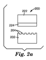
図2a〜2cは、LITEフィルムを使用して微細複製工具を製造するためのLITEの使用を例示する図である。図2aに示されるように、微細複製工具を製造することは、フィルム200及び微細複製工具202の使用を伴う。フィルム200は、基材222及びLTHC層のような追加の層224を有し、これは基材102及びLTHC層104に対応してもよい。微細複製工具202は、微細構造204を有する。図2bに例示されるように、LITE微細複製工具を製造するために、微細構造204がLTHC層224と接触した状態で、工具202にフィルム200がラミネートされ、次にフィルム200は工具202に対して、それにラミネートされる間に、レーザー光線228及び本明細書に記載されるもののような熱画像化プロセスを使用して画像化される。画像化及び画像化されたフィルム200を工具202から取り除くのに続いて、LTHC層224は、図2cに例示されるように、工具202上の微細構造の画像化された部分に対応する微細複製パターン226を有する。微細複製パターンを有する画像化されたフィルムは、その後、例えば再利用可能な工具として使用されることもできるし、又はそれは画像化されたフィルムの金属の複写若しくはレプリカを製造するために使用されることもできる。
2a-2c are diagrams illustrating the use of LITE to produce a microreplicated tool using a LITE film. As shown in FIG. 2 a, manufacturing a microreplication tool involves the use of a
図3は、エンボス加工されたライナー及び製品を含むフィルム構築物250の図である。エンボス加工されたライナーは、基材252及び構造化されたLTHC 254から構成され、これは基材102及びLTHC層104に対応してもよく、上記の技術を使用してエンボス加工されて、その中に構造257を付与することができる。製品は、基材258及び材料層256から構成され、これはエンボス加工されたライナーをそれにラミネート又は適用することにより構造化される。図4は、エンボス加工されたライナーから製造されたエンボス加工された製品の図である。エンボス加工された製品は、基材258、及びライナーの構造化されたLTHC254から付与された構造259を有する材料256から構成される。構造化されたライナーの例は、米国特許第6,838,150号に記載されており、これは参照により本明細書に組み込まれる。
FIG. 3 is an illustration of a
微細複製工具のためのLITEフィルム
図5aは、微細構造化されたプリズムを有する微細複製工具300の斜視図である。図5bは、微細複製工具300を使用して製造されたLITE工具302の斜視図である。特に、微細複製工具302は、基材304及びLTHC層のような追加の層306を有するLITEフィルムを含み、これは基材102及びLTHC層104に対応してもよい。工具302は、図2a〜2cに関して記載されたのと同じ又は同様のプロセスを使用して製造されることができる。特に、LITE工具302を製造するために、微細構造化されたプリズムがLTHC層306に接触した状態で、工具300にそれがラミネートされ、次にそれは工具300に対して画像化される。画像化に続いて、層306は、非画像化部分308により分離された微細構造305を有してエンボス加工される。
LITE film for microreplication tool FIG. 5a is a perspective view of a
LITEプロセスの変形は、より複雑なLITE工具を創出するために、異なる微細構造化パターンを有する複数の微細複製工具の使用を伴う。図6aは、各々が異なるピッチ及び高さを有する微細構造化されたプリズムを有する3つの微細複製工具400、402、及び404の斜視図である。図6bは、図6aに示される微細複製工具を使用して製造されたLITE工具406の斜視図である。特に、微細複製工具406は、基材408及びLTHC層のような追加の層410を有するLITEフィルムを含み、これは基材102及びLTHC層104に対応してもよい。工具406は、図2a〜2cに関して記載されたのと同じ又は同様のプロセスを使用して製造されることができる。特に、LITE工具406を製造するために、微細構造化されたプリズムが画像化の間にLTHC層410に接触した状態で、工具400、402、及び404に対して順番にそれがラミネートされ画像化される。画像化に続いて、層410は、それぞれ工具404、402、及び400に対応し非画像化部分418及び420により分離された微細構造412、414、及び416を有してエンボス加工される。
Variations in the LITE process involve the use of multiple microreplication tools with different microstructured patterns to create more complex LITE tools. FIG. 6a is a perspective view of three
構造上構造を有するLITEフィルム
LITEプロセスの別の変形は、それらの表面上にナノ構造化形状を有する、プリズムのようなマイクロメートル規模の形状を含む構造上構造の配列又はパターンの創出を可能にする。例として、ナノ構造化形状は、1次元又は2次元の回折格子を含むことができる。図7a〜7cは、構造上構造パターンを有する微細複製工具を製造するためのLITEの使用を例示する図である。図7aに示されるように、構造上構造の微細複製工具を製造することは、フィルム500及び微細複製工具502の使用を伴う。フィルム500は、基材520及びLTHC層のような追加の層524を有し、これは基材102及びLTHC層104に対応してもよい。LTHC層524はナノ構造化表面525を有し、微細複製工具502は微細構造504を有する。図7bに例示されるように、LITE微細複製工具を製造するために、微細構造504がLTHC層524に接触した状態で、工具502にフィルム500がラミネートされ、次にフィルム500は工具502に対して、それにラミネートされる間に、レーザー光線521及び本明細書に記載されるもののような熱画像化プロセスを使用して画像化される。画像化及び画像化されたフィルム500を工具502から取り除くのに続いて、LTHC層524は、図7cに例示されるように、ナノ構造化表面を有し工具502上の微細構造の画像化された部分に対応する微細複製パターン528を有する。
LITE films with structural structure Another variation of the LITE process enables the creation of arrays or patterns of structural structures, including prism-like micrometer-scale shapes, with nanostructured shapes on their surface To do. As an example, the nanostructured shape can include a one-dimensional or two-dimensional diffraction grating. 7a-7c are diagrams illustrating the use of LITE to produce a microreplication tool having a structural pattern in structure. As shown in FIG. 7 a, producing a structurally structured microreplication tool involves the use of a
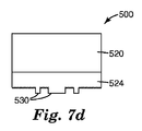
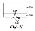
図7d〜7fは、構造上構造パターンの代替物を例示する。図7dは、工具502に対してエンボス加工されたLITEフィルム500の図であり、その場合、図7bに関して記載されたように、エンボス加工プロセスの間に、区域530中において特定のナノ構造が取り除かれている。特に、工具502に対して画像化される区域530中のナノ構造化形状の破壊を生じさせるために、十分なエネルギーのレーザー光線521を使用することができる。別の変形では、図7eに示されるように、工具532は、微細構造化形状536、及び微細構造化形状と微細構造化形状との間、又は微細構造化形状に混ざってナノ構造化形状534を含む構造上構造パターンを有する。図7fは、工具532及び上記のようなエンボス加工プロセスを使用してエンボス加工された、基材538及びLTHCのような追加の層540を含むLITEフィルムを例示する図である。工具532に対してエンボス加工した後、LITEフィルムは、工具532上の微細構造化形状536に対応する空間544により分離された微細構造化形状上のナノ構造化形状542を有する。
7d-7f illustrate structural structural pattern alternatives. FIG. 7d is an illustration of a
LITIプロセスにおけるLITEフィルム
図8a〜8cは、転写層の一部をレセプタ608に転写するために、転写層606を有するエンボス加工されたLITEフィルム600を画像化するLITIプロセスを例示する図である。図8aに示されるように、LITEフィルム600は、転写層でコーティングされたエンボス加工されたLITEフィルムから構成される。LITEフィルムは、基材602及び上記のような微細複製工具に対して構造を画像化するプロセスを使用して製造された構造605を有するLTHC層604から構成される。転写層606は、構造化されたLTHC層604に適用される。画像化の間に、図8bに示されるように、LITEフィルムはレセプタと密接に接触して保持されると同時に、転写層はレセプタ608に対して保持され、レーザー光線610はLITEフィルムを照射して、レセプタ608に転写層606の一部の転写を生じる。図8cに示されるように、LITEフィルムが取り除かれると、転写層606の転写された部分612は、レセプタ608上に残り、転写された部分612は、LITEフィルムのLTHC604中の構造605により付与されるような構造614を有する。
LITE Film in the LITI Process FIGS. 8 a-8 c are diagrams illustrating a LITI process for imaging an
代表的なLITIドナーフィルムの様々な層及びそれを画像化する方法は、米国特許第6,866,979号、同第6,586,153号、同第6,468,715号、同第6,284,425号、及び同第5,725,989号により完全に記載されており、これらのすべては、完全に説明されているかのように、参照により本明細書に組み込まれる。 Various layers of representative LITI donor films and methods for imaging them are described in US Pat. Nos. 6,866,979, 6,586,153, 6,468,715, , 284,425, and 5,725,989, all of which are hereby incorporated by reference as if fully set forth.
フィルム600は、LTHC層606とエンボス加工層608との間に任意の中間層を有することができる。任意の中間層は、層の転写された部分の損傷及び汚染を最小限にするために熱ドナーに使用されることができ、また層の転写された部分のひずみを減少させ得る。中間層はまた、転写層と熱転写ドナーの残りの部分との接着に影響を与えることができる。典型的には、中間層は、高い耐熱性を有する。好ましくは、中間層は、画像化条件下において変形又は化学的に分解せず、特に、転写された画像が機能しない状態になる程度まで、変形又は化学的に分解しない。中間層は、典型的には、転写プロセスの間、LTHC層と接触した状態のままであり、転写層と共に実質的に転写されない。好適な中間層には、例えば、ポリマーフィルム、金属層(例えば、蒸着金属層)、無機層(例えば、ゾル−ゲル付着層及び無機酸化物(例えば、シリカ、チタニア、及びその他の金属酸化物)の蒸着層)、並びに有機/無機複合層が挙げられる。中間層材料として好適な有機材料には、熱硬化性材料と熱可塑性材料との両方が挙げられる。好適な熱硬化性材料には、架橋された又は架橋可能なポリアクリレート、ポリメタクリレート、ポリエステル、エポキシ、及びポリウレタンが挙げられるがこれらに限定されない、熱、放射線、又は化学処理によって架橋され得る樹脂が挙げられる。熱硬化性材料は、例えば、熱可塑性前駆体としてLTHC層上にコーティングされ、続いて架橋されて、架橋された中間層を形成してもよい。中間層は、例えば、光開始剤、界面活性剤、顔料、可塑剤、及びコーティング補助剤を含む添加剤を含有してもよい。
The
転写層606は、典型的には、レセプタ608に転写するための1つ以上の層を含む。これらの1つ以上の層は、有機、無機、有機金属、又はその他の材料を使用して形成されてもよい。有機材料には、例えば、小分子材料、ポリマー、オリゴマー、デンドリマー、及び超分枝材料が挙げられる。熱転写層は、例えば、ディスプレイ装置の発光素子、電子回路、レジスタ、コンデンサ、ダイオード、整流器、エレクトロルミネセントランプ、記憶素子、電界効果トランジスタ、バイポーラトランジスタ、単接トランジスタ、金属酸化物半導体(MOS)トランジスタ、金属−絶縁体−半導体トランジスタ、電荷結合素子、絶縁体−金属−絶縁体積み重ね体、有機導電体−金属−有機導電体積み重ね体、集積回路、光検出器、レーザー、レンズ、導波管、格子、ホログラフィック素子、信号処理のためのフィルタ(例えば、アドドロップフィルタ、利得平坦化フィルタ、遮断フィルタなど)、光学フィルタ、鏡、スプリッタ、カップラー、コンバイナ、モジュレータ、センサ(例えば、エバネセントセンサ、位相変調センサ、干渉センサなど)、光学キャビティ、圧電素子、強誘電体素子、薄膜電池、又はこれらの組み合わせ、例えば、光ディスプレイのための能動マトリックス配列としての電界効果トランジスタ及び有機エレクトロルミネセントランプの組み合わせを形成するために使用することができる転写層を含むことができる。その他の品目は、マルチコンポーネント転写アセンブリ又は単一層を転写することによって形成されてもよい。
The
転写層606の少なくとも一部を受容するための永久レセプタ608は、透明なフィルム、ディスプレイ用ブラックマトリックス、電子ディスプレイの受動及び能動部分、金属、半導体、ガラス、様々な紙、並びにプラスチックが挙げられるがこれらに限定されない、特定の用途に好適ないかなる品目であってもよい。レセプタ基材の例には、陽極酸化アルミニウム及びその他の金属、プラスチックフィルム(例えば、PET、ポリプロピレン)、酸化インジウムスズでコーティングされたプラスチックフィルム、ガラス、酸化インジウムスズでコーティングされたガラス、フレキシブル回路、回路基板、シリコン又はその他の半導体、並びに多様な異なる種類の紙(例えば、充填若しくは無充填紙、光沢紙、又はコーティングされた紙)が挙げられる。
図9aは、レーザー走査の90°の配向を使用してLITE工具を製造するためのプロセスを例示する図であり、図9bは、100マイクロメートルの水平ピッチを有する微細構造を有し図9aに示される走査配向を使用して製造されたサンプルLITE工具の画像である。図10aは、レーザー走査の45°の配向を使用してLITE工具を製造するためのプロセスを例示する図であり、図10bは、100マイクロメートルの対角ピッチを有する微細構造を有し図10aに示される走査配向を使用して製造されたサンプルLITE工具の画像である。これらの工具は、上記のような微細複製工具に対してLITEフィルムを画像化するプロセスを使用して製造されることができる。図9a、9b、10a、及び10bはまた、形状の様々なパターンをLITEフィルム中にエンボス加工するために、どのようにしてレーザー走査ラインと工具とのレジストレーションが制御され得るかを例示する。例えば、いくつかの実施形態では、工具は、微細構造化形状の高解像度の規則的配列を有し、LITEフィルムはその中にパターン化された情報を持たず、レーザーパターンは、高い位置精度を有するが、そうした実施形態では、エンボス加工後にLITEフィルム中に結果として生じるパターンは、好ましくはレーザー走査ラインより小さい、高解像度のエンボス加工された形状を有し、高い位置精度を含む。他の実施形態は、エンボス加工された形状の様々な構成を有してLITEフィルムをエンボス加工するために、レーザーシステムと工具とのレジストレーションが必要な場合がある。ひとたびLITEフィルムがエンボス加工されたら、それは、その後でレーザーシステムとLITEフィルムを、エンボス加工されたパターンに従って位置合わせするために、基準マーク又は任意の他の種類のレジストレーションマークを含むことができる。ウェブ系システムにおける基準の使用の例は、米国特許第7,187,995号に記載されており、これは参照により本明細書に組み込まれる。 FIG. 9a illustrates a process for manufacturing a lite tool using 90 ° orientation of laser scanning, and FIG. 9b has a microstructure with a horizontal pitch of 100 micrometers and FIG. 4 is an image of a sample LITE tool manufactured using the scan orientation shown. 10a is a diagram illustrating a process for manufacturing a lite tool using 45 ° orientation of laser scanning, and FIG. 10b has a microstructure with a diagonal pitch of 100 micrometers. FIG. 3 is an image of a sample LITE tool manufactured using the scan orientation shown in FIG. These tools can be manufactured using a process that images a ITE film against a microreplication tool as described above. FIGS. 9a, 9b, 10a, and 10b also illustrate how the registration of laser scan lines and tools can be controlled to emboss various patterns of shapes into a lite film. For example, in some embodiments, the tool has a high resolution regular array of microstructured shapes, the LITE film has no information patterned therein, and the laser pattern has high positional accuracy. In such embodiments, however, the resulting pattern in the LITE film after embossing preferably has a high resolution embossed shape that is smaller than the laser scan line and includes high positional accuracy. Other embodiments may require registration between the laser system and the tool to emboss the LITE film with various configurations of embossed shapes. Once the LITE film is embossed, it can then include a fiducial mark or any other type of registration mark to align the laser system and the LITE film according to the embossed pattern. An example of the use of criteria in a web-based system is described in US Pat. No. 7,187,995, which is incorporated herein by reference.
LITEフィルム1
LITEフィルム1は、PETフィルム上に2つのコーティングされた層を含み、次の方式で調製された。逆マイクログラビアコーター(康井精機(Yasui Seiki)CAG−150)を使用してLTHC−1(表1)をコーティングすることにより、LTHCが0.07mm(2.88ミル)厚さのPETフィルム基材(M7Qフィルム、デュポン・テイジン・フィルムズ(DuPont Teijin Films)、バージニア州ホープウェル(Hopewell))上に適用された。コーティングは、およそ2.7マイクロメートルのLTHCの乾燥厚さを実現するために、インラインで乾燥され、紫外線下で光硬化された。硬化されたコーティングは、1064ナノメートル(nm)で、およそ1.18の光学密度を有した。
LITE film 1
LITE film 1 comprised two coated layers on a PET film and was prepared in the following manner. By coating LTHC-1 (Table 1) using a reverse micro gravure coater (Yasui Seiki CAG-150), the PET film base having an LTHC of 0.07 mm (2.88 mil) thick Applied on the material (M7Q film, DuPont Teijin Films, Hopewell, VA). The coating was dried inline and photocured under ultraviolet light to achieve a dry thickness of LTHC of approximately 2.7 micrometers. The cured coating had an optical density of approximately 1.18 at 1064 nanometers (nm).
逆マイクログラビアコーター(康井精機(Yasui Seiki)CAG−150)を使用してCC−1(表2)をコーティングすることにより、クリアコートがLTHC層に適用された。コーティングは、およそ1.1マイクロメートルのクリアコートの乾燥厚さを実現するために、インラインで乾燥され、紫外線下で光硬化された。 A clear coat was applied to the LTHC layer by coating CC-1 (Table 2) using a reverse micro gravure coater (Yasui Seiki CAG-150). The coating was dried inline and photocured under ultraviolet light to achieve a clear coat dry thickness of approximately 1.1 micrometers.

LITEフィルム2
LITEフィルム2は、PETフィルム上に単一のコーティングされた層を含み、次の方式で調製された。逆マイクログラビアコーター(康井精機(Yasui Seiki)CAG−150)を使用してLTHC−2(表3)をコーティングすることにより、LTHC層が0.07mm(2.88ミル)厚さのPETフィルム基材(M7Qフィルム、デュポン・テイジン・フィルムズ(DuPont Teijin Films)、バージニア州ホープウェル(Hopewell))上に適用された。コーティングは、およそ3.7マイクロメートルのLTHCの乾燥厚さを実現するために、インラインで乾燥された。乾燥コーティングは、808nmで、およそ3.2の光学密度を有した。
LITE film 2
LITE film 2 contained a single coated layer on a PET film and was prepared in the following manner. By coating LTHC-2 (Table 3) using a reverse micro gravure coater (Yasui Seiki CAG-150), the LTHC layer is 0.07 mm (2.88 mil) thick PET film It was applied on a substrate (M7Q film, DuPont Teijin Films, Hopewell, VA). The coating was dried in-line to achieve a dry thickness of LTHC of approximately 3.7 micrometers. The dried coating had an optical density of approximately 3.2 at 808 nm.
ニッケル電鋳工具
パターン付きシリコンウエファーのマスターが、シプリー(Shipley)1813フォトレジスト(ローム・アンド・ハース・エレクトロニック・マテリアルズ(Rohm and Haas Electronic Materials)、デラウェア州ニューアーク(Newark))でコーティングされた基準配向の10.2cm(4インチ)シリコンウエファー上に製作された。レジストは、標準的I−ラインマスクアライナ(クインテル(Quintel)、カリフォルニア州サンノゼ(San Jose))及び電子ビーム書き込みクロム加工ガラスフォトツールを使用して、コンタクトフォトリソグラフィーの手段により、5マイクロメートル線状形状の小さい正方形配列でパターン付けされた。シプリー(Shipley)レジストのために標準的現像技術が使用されたが、レジスト上で最終的なハードベークは実行されなかった。サンプルは次に、誘導結合プラズマ発生器(オックスフォード・インスツルメンツ(Oxford Instruments)、英国エインシャム(Eynsham))装備反応性イオンエッチング工具でエッチングされた。サンプルは、C4F8及びO2、70WのRF電力、1600WのICP電力、及び0.73Pa(5.5ミリトール)の圧力を使用して、およそ0.5マイクロメートルのエッチング深さまで2分間エッチングされた。サンプルは次に、加熱された超音波フォトレジストストリッパー浴の中で、シプリー(Shipley)1165レジストストリッパーを使用してレジストが剥離されて、マスター工具を得た。
Nickel Electroforming Tool Patterned Silicon Wafer Master Coated with Shipley 1813 Photoresist (Rohm and Haas Electronic Materials, Newark, Del.) It was fabricated on a 10.2 cm (4 inch) silicon wafer with a reference orientation. The resist is 5 micrometer linear by means of contact photolithography using a standard I-line mask aligner (Quintel, San Jose, Calif.) And an electron beam written chrome-processed glass phototool. Patterned with small square arrays. Standard development techniques were used for Shipley resist, but no final hard bake was performed on the resist. The sample was then etched with a reactive ion etching tool equipped with an inductively coupled plasma generator (Oxford Instruments, Eynsham, UK). The samples were C 2 F 8 and O 2 , 70 W RF power, 1600 W ICP power, and 0.73 Pa (5.5 mTorr) pressure for 2 minutes to an etch depth of approximately 0.5 micrometers. Etched. The sample was then stripped using a Shipley 1165 resist stripper in a heated ultrasonic photoresist stripper bath to obtain a master tool.
マスター工具は、およそ0.64mm(25ミル)の厚さまで、電解ニッケルでめっきされた。ニッケルめっきの前に、ウエファーを導電性にするために、1000オングストロームの気相コーティングされたニッケルが表面上に蒸着された。ニッケルめっきは、ニッケルの均一の導電性層が構築されることを確実にするための低蒸着速度による6時間の予備めっきと、0.64mm(25ミル)の目標の厚さ値を実現するためのその後のより迅速な蒸着からなる2工程で実行された。電鋳法により、およそ1.29マイクロメートル(AFM分析により測定されたとき)の均一高さを有する5マイクロメートル幅の線状形状の配列を有するニッケル電鋳工具を得た。 The master tool was plated with electrolytic nickel to a thickness of approximately 0.64 mm (25 mils). Prior to nickel plating, 1000 Å vapor phase coated nickel was deposited on the surface to make the wafer conductive. Nickel plating to achieve a 6 hour pre-plating with a low deposition rate to ensure that a uniform conductive layer of nickel is built, and a target thickness value of 0.64 mm (25 mils) Was performed in two steps consisting of a subsequent, more rapid deposition. The electroforming process yielded a nickel electroforming tool having a 5 micrometer wide linear array with a uniform height of approximately 1.29 micrometers (as measured by AFM analysis).
LITE手順
LITE工具を創出するために、LITEフィルムは、構造化工具と密接に接触させられた。フィルムと工具との間の空気は、真空チャックアセンブリにより取り除かれ、フィルム−工具ラミネートは、フィルムの支持層(基材)を通してレーザー放射線に露光した。レーザーシステムAの露光(λ=1064nm)については、走査速度は0.635m/sであり、画像平面中のスポット電力は1Wであり、放射線量は、0.85J/cm2であった。レーザーシステムBの露光(λ=808nm)については、走査速度は1.0m/sであり、スポット電力は1.3Wであり、放射線量は、1.3J/cm2であった。
LITE Procedure To create a LITE tool, the LITE film was brought into intimate contact with the structured tool. The air between the film and the tool was removed by a vacuum chuck assembly and the film-tool laminate was exposed to laser radiation through the support layer (substrate) of the film. For laser system A exposure (λ = 1064 nm), the scanning speed was 0.635 m / s, the spot power in the image plane was 1 W, and the radiation dose was 0.85 J / cm 2 . For laser system B exposure (λ = 808 nm), the scanning speed was 1.0 m / s, the spot power was 1.3 W, and the radiation dose was 1.3 J / cm 2 .
LITEフィルム2のエンボス加工された形状並びにニッケル電鋳及びIDFの対応する形状を特徴付けるために、タッピングモードにおいて原子間力顕微鏡法(AFM)が使用された。TMFフィルム及び対応するLITEフィルム2の分析のために使用された機器は、デジタル・インスツルメンツ(Digital Instruments)のディメンション(Dimension)3100SPMであった。ナノ工具及び対応するLITEフィルム2の分析のために使用された機器は、デジタル・インスツルメンツ(Digital Instruments)のディメンション(Dimension)5000SPMであった。使用されたプローブは、約40N/Mの力定数を有するオリンパス(Olympus)OTESP単結晶シリコンレバーであった。設定点の値は、もとの自由空間の振幅点(2.0V)の75%に設定された。
(態様1)
基材と、
前記基材にオーバーレイする光熱変換層と、
を含んでなり、
LITEフィルムの表面が、その上に選択的にエンボス加工された微細構造化表面を有することができる、
レーザー励起熱エンボス加工(LITE)フィルム。
(態様2)
前記光熱変換層に適用されたフィルムと、
前記フィルムと前記光熱変換層との間の材料と、
を更に含み、
前記LITEフィルムが、前記光熱変換層の前記微細構造化表面の適用によって、前記材料の構造化を生じさせるライナーを含む、態様1に記載のLITEフィルム。
(態様3)
前記光熱変換層が、金属、顔料、又は染料の内の少なくとも1種を含む、態様1に記載のLITEフィルム。
(態様4)
前記光熱変換層が、約0.01マイクロメートル〜約10マイクロメートルの厚さを有する、態様1に記載のLITEフィルム。
(態様5)
前記微細構造化表面が、不連続の微細構造化形状を有する、態様1に記載のLITEフィルム。
(態様6)
前記微細構造化表面が、ナノ構造化形状を有する、態様1に記載のLITEフィルム。
(態様7)
前記微細構造化表面が、微細構造化された光学要素を有する、態様1に記載のLITEフィルム。
(態様8)
前記微細構造化表面が、微細構造化されたプリズムを有する、態様1に記載のLITEフィルム。
(態様9)
微細複製工具を製作する方法であって、
基材と前記基材にオーバーレイする光熱変換層とを含む、レーザー誘起熱エンボス加工(LITE)フィルムを提供することと、
前記光熱変換層が前記微細構造に接触した状態で、微細構造のパターンを含むマスター工具に、前記LITEフィルムをラミネートすることと、
前記LITEフィルムをパターンごとに画像化して、前記光熱変換層を選択的に露光することと、
前記マスター工具を取り除いて、前記LITEフィルム上に、前記マスター工具の前記微細構造に対応する微細構造化パターンを製造することと、
を含んでなる、方法。
(態様10)
前記光熱変換層に、転写層を適用することを更に含む、態様9に記載の方法。
(態様11)
前記提供する工程が、前記LITEフィルムに、金属、顔料、又は染料の内の少なくとも1種を含む、前記光熱変換層を提供することを含む、態様9に記載の方法。
(態様12)
前記提供する工程が、前記LITEフィルムに、ナノ構造化表面を含む前記光熱変換層を提供することを含む、態様9に記載の方法。
(態様13)
微細複製工具を製作する方法であって、
基材と前記基材にオーバーレイする光熱変換層とを含む、レーザー誘起熱エンボス加工(LITE)フィルムを提供することと、
前記光熱変換層が前記微細構造の第1パターンと接触した状態で、微細構造の第1パターンを含む第1マスター工具に、前記LITEフィルムをラミネートすることと、
前記LITEフィルムをパターンごとに画像化して、前記微細構造の第1パターンで前記光熱変換層を選択的に露光することと、
前記第1マスター工具から前記LITEフィルムを取り除くことと、
前記光熱変換層が前記微細構造の第2パターンに接触した状態で、微細構造の第2パターンを含む第2マスター工具に、前記LITEフィルムをラミネートすることと、
前記LITEフィルムをパターンごとに画像化して、前記微細構造の第2パターンで前記光熱変換層を選択的に露光することと、
前記第2マスター工具から前記LITEフィルムを取り除いて、前記微細構造の第1及び第2パターンの組み合わせに対応するパターンを有する前記LITEフィルムを製造することと、
を含んでなる、方法。
(態様14)
前記光熱変換層に転写層を適用することを更に含む、態様13に記載の方法。
(態様15)
前記提供する工程が、前記LITEフィルムに、金属、顔料、又は染料の内の少なくとも1種を含む前記光熱変換層を提供することを含む、態様13に記載の方法。
(態様16)
前記提供する工程が、前記LITEフィルムに、ナノ構造化表面を含む前記光熱変換層を提供することを含む、態様13に記載の方法。
(態様17)
前記微細構造の第1パターンが、前記微細構造の第2パターンと異なる、態様13に記載の方法。
(態様18)
前記パターンごとの画像化工程が、前記LITEフィルムに、前記微細構造の第2パターンに対してゼロでない角度で、微細構造の第1パターンを画像化することを含む、態様13に記載の方法。
(態様19)
前記微細構造の第1パターン及び第2パターンが、それぞれ、微細構造化プリズムの配列を含む、態様13に記載の方法。
(態様20)
前記微細構造の第1パターン中の前記微細構造化プリズムの配列が、前記微細構造の第2パターン中の前記微細構造化プリズムの配列と異なるピッチを有する、態様19に記載の方法。
(態様21)
熱ドナーフィルムを製造するために使用されるレーザー誘起熱エンボス加工(LITE)フィルムであって、
基材と、
前記基材にオーバーレイする光熱変換層であって、前記LITEフィルムの表面は、その上に選択的にエンボス加工された微細構造化表面を有することができる、光熱変換層と、
前記微細構造化表面を有することができる前記光熱変換層の前記表面に適用される転写層と、
を含んでなり、
前記LITEフィルムがレセプタと密接に接触して保持されると同時に、前記転写層が前記レセプタに対して保持されている間に、前記LITEフィルムが照射される場合に、前記レセプタに前記転写層の一部の転写を生じる、レーザー誘起熱エンボス加工(LITE)フィルム。
(態様22)
構造化された転写層を有する熱ドナーフィルムを製造する方法であって、
基材と前記基材にオーバーレイする光熱変換層とを含むレーザー誘起熱エンボス加工(LITE)フィルムを提供することと、
前記光熱変換層が前記微細構造に接触した状態で、微細構造のパターンを含むマスター工具に、前記LITEフィルムをラミネートすることと、
前記LITEフィルムをパターンごとに画像化して、前記光熱変換層を選択的に露光することと、
前記マスター工具を取り除いて、前記LITEフィルム上に、前記マスター工具の前記微細構造に対応する微細構造化パターンを製造することと、
前記LITEフィルム上の前記微細構造化パターンに、転写層を適用することと、
を含んでなり、
前記LITEフィルムが、レセプタと密接に接触して保持されると同時に、前記転写層が前記レセプタに対して保持されている間に、前記LITEフィルムが照射される場合に、前記レセプタに前記転写層の一部の転写を生じる、方法。
Atomic force microscopy (AFM) was used in tapping mode to characterize the embossed shape of LITE film 2 and the corresponding shape of nickel electroforming and IDF. The instrument used for the analysis of the TMF film and the corresponding LITE film 2 was Digital Instruments Dimension 3100 SPM. The instrument used for analysis of the nanotool and the corresponding LITE film 2 was a Digital Instruments Dimension 5000 SPM. The probe used was an Olympus OTESP single crystal silicon lever with a force constant of about 40 N / M. The value of the set point was set to 75% of the original free space amplitude point (2.0 V).
(Aspect 1)
A substrate;
A photothermal conversion layer overlaid on the substrate;
Comprising
The surface of the LITE film can have a microstructured surface selectively embossed thereon,
Laser excited thermal embossing (LITE) film.
(Aspect 2)
A film applied to the photothermal conversion layer;
A material between the film and the photothermal conversion layer;
Further including
The lite film of aspect 1, wherein the lite film comprises a liner that causes structuring of the material by application of the microstructured surface of the photothermal conversion layer.
(Aspect 3)
The lite film according to aspect 1, wherein the light-to-heat conversion layer contains at least one of a metal, a pigment, and a dye.
(Aspect 4)
The LITE film of embodiment 1, wherein the photothermal conversion layer has a thickness of about 0.01 micrometer to about 10 micrometers.
(Aspect 5)
The lite film of aspect 1, wherein the microstructured surface has a discontinuous microstructured shape.
(Aspect 6)
The lite film of aspect 1, wherein the microstructured surface has a nanostructured shape.
(Aspect 7)
The ITE film of embodiment 1, wherein the microstructured surface has microstructured optical elements.
(Aspect 8)
The lite film of aspect 1, wherein the microstructured surface comprises a microstructured prism.
(Aspect 9)
A method of making a micro-replication tool,
Providing a laser-induced thermal embossing (LITE) film comprising a substrate and a photothermal conversion layer overlaying the substrate;
Laminating the LITE film to a master tool including a fine structure pattern in a state where the photothermal conversion layer is in contact with the fine structure;
Imaging the LITE film pattern by pattern and selectively exposing the photothermal conversion layer;
Removing the master tool, producing a microstructured pattern on the lite film corresponding to the microstructure of the master tool;
Comprising a method.
(Aspect 10)
The method of embodiment 9, further comprising applying a transfer layer to the photothermal conversion layer.
(Aspect 11)
10. The method of aspect 9, wherein the providing step comprises providing the light-to-heat conversion layer comprising at least one of a metal, a pigment, or a dye on the LITE film.
(Aspect 12)
10. The method of aspect 9, wherein the providing step comprises providing the LITE film with the photothermal conversion layer comprising a nanostructured surface.
(Aspect 13)
A method of making a micro-replication tool,
Providing a laser-induced thermal embossing (LITE) film comprising a substrate and a photothermal conversion layer overlaying the substrate;
Laminating the LITE film on a first master tool including a first microstructured pattern with the photothermal conversion layer in contact with the first microstructured pattern;
Imaging the LITE film pattern by pattern and selectively exposing the photothermal conversion layer with the first pattern of the microstructure;
Removing the LITE film from the first master tool;
Laminating the LITE film on a second master tool including the second pattern of fine structure in a state where the photothermal conversion layer is in contact with the second pattern of fine structure;
Imaging the LITE film pattern by pattern and selectively exposing the photothermal conversion layer with the second pattern of the microstructure;
Removing the LITE film from the second master tool to produce the LITE film having a pattern corresponding to a combination of the first and second patterns of the microstructure;
Comprising a method.
(Aspect 14)
14. The method according to aspect 13, further comprising applying a transfer layer to the photothermal conversion layer.
(Aspect 15)
14. The method of aspect 13, wherein the providing step comprises providing the light-to-heat conversion layer comprising at least one of a metal, pigment, or dye on the LITE film.
(Aspect 16)
14. The method of aspect 13, wherein the providing step comprises providing the LITE film with the photothermal conversion layer comprising a nanostructured surface.
(Aspect 17)
14. A method according to aspect 13, wherein the first microstructured pattern is different from the second microstructured pattern.
(Aspect 18)
14. The method of aspect 13, wherein the pattern-by-pattern imaging step comprises imaging a microstructure first pattern on the ITE film at a non-zero angle with respect to the microstructure second pattern.
(Aspect 19)
14. The method of aspect 13, wherein the microstructured first pattern and the second pattern each comprise an array of microstructured prisms.
(Aspect 20)
20. The method of aspect 19, wherein the arrangement of the microstructured prisms in the first microstructured pattern has a different pitch than the arrangement of the microstructured prisms in the second microstructured pattern.
(Aspect 21)
A laser induced thermal embossing (LITE) film used to produce a thermal donor film,
A substrate;
A light-to-heat conversion layer overlaying the substrate, wherein the surface of the LITE film can have a microstructured surface selectively embossed thereon;
A transfer layer applied to the surface of the photothermal conversion layer, which can have the microstructured surface;
Comprising
The LITE film is held in intimate contact with the receptor, and at the same time, when the LITE film is irradiated while the transfer layer is held against the receptor, Laser induced thermal embossing (LITE) film that produces some transfer.
(Aspect 22)
A method for producing a thermal donor film having a structured transfer layer comprising:
Providing a laser-induced thermal embossing (LITE) film comprising a substrate and a photothermal conversion layer overlaying the substrate;
Laminating the LITE film to a master tool including a fine structure pattern in a state where the photothermal conversion layer is in contact with the fine structure;
Imaging the LITE film pattern by pattern and selectively exposing the photothermal conversion layer;
Removing the master tool, producing a microstructured pattern on the lite film corresponding to the microstructure of the master tool;
Applying a transfer layer to the microstructured pattern on the LITE film;
Comprising
The transfer layer is applied to the receptor when the LITE film is held in intimate contact with the receptor and at the same time the LITE film is irradiated while the transfer layer is held against the receptor. A method that results in the transcription of part of.
Claims (2)
基材と前記基材にオーバーレイする光熱変換層とを含む、レーザー誘起熱エンボス加工(LITE)フィルムを提供することと、
前記光熱変換層が前記微細構造に接触した状態で、微細構造のパターンを含むマスター工具に、前記LITEフィルムをラミネートすることと、
前記LITEフィルムをパターンごとに画像化して、前記光熱変換層を選択的に露光することと、
前記マスター工具を取り除いて、前記LITEフィルム上に、前記マスター工具の前記微細構造に対応する微細構造化パターンを製造することと、
を含んでなる、方法。 A method of making a micro-replication tool,
Providing a laser-induced thermal embossing (LITE) film comprising a substrate and a photothermal conversion layer overlaying the substrate;
Laminating the LITE film to a master tool including a fine structure pattern in a state where the photothermal conversion layer is in contact with the fine structure;
Imaging the LITE film pattern by pattern and selectively exposing the photothermal conversion layer;
Removing the master tool, producing a microstructured pattern on the lite film corresponding to the microstructure of the master tool;
Comprising a method.
基材と前記基材にオーバーレイする光熱変換層とを含むレーザー誘起熱エンボス加工(LITE)フィルムを提供することと、
前記光熱変換層が前記微細構造に接触した状態で、微細構造のパターンを含むマスター工具に、前記LITEフィルムをラミネートすることと、
前記LITEフィルムをパターンごとに画像化して、前記光熱変換層を選択的に露光することと、
前記マスター工具を取り除いて、前記LITEフィルム上に、前記マスター工具の前記微細構造に対応する微細構造化パターンを製造することと、
前記LITEフィルム上の前記微細構造化パターンに、転写層を適用することと、
を含んでなり、
前記LITEフィルムが、レセプタと密接に接触して保持されると同時に、前記転写層が前記レセプタに対して保持されている間に、前記LITEフィルムが照射される場合に、前記レセプタに前記転写層の一部の転写を生じる、方法。 A method for producing a thermal donor film having a structured transfer layer comprising:
Providing a laser-induced thermal embossing (LITE) film comprising a substrate and a photothermal conversion layer overlaying the substrate;
Laminating the LITE film to a master tool including a fine structure pattern in a state where the photothermal conversion layer is in contact with the fine structure;
Imaging the LITE film pattern by pattern and selectively exposing the photothermal conversion layer;
Removing the master tool, producing a microstructured pattern on the lite film corresponding to the microstructure of the master tool;
Applying a transfer layer to the microstructured pattern on the LITE film;
Comprising
The transfer layer is applied to the receptor when the LITE film is held in intimate contact with the receptor and at the same time the LITE film is irradiated while the transfer layer is held against the receptor. A method that results in the transcription of part of.
Applications Claiming Priority (3)
| Application Number | Priority Date | Filing Date | Title |
|---|---|---|---|
| US11/689,853 US20080233404A1 (en) | 2007-03-22 | 2007-03-22 | Microreplication tools and patterns using laser induced thermal embossing |
| US11/689,853 | 2007-03-22 | ||
| PCT/US2008/055403 WO2008118610A1 (en) | 2007-03-22 | 2008-02-29 | Microreplication tools and patterns using laser induced thermal embossing |
Publications (3)
| Publication Number | Publication Date |
|---|---|
| JP2010522102A JP2010522102A (en) | 2010-07-01 |
| JP2010522102A5 JP2010522102A5 (en) | 2011-03-31 |
| JP5475474B2 true JP5475474B2 (en) | 2014-04-16 |
Family
ID=39775041
Family Applications (1)
| Application Number | Title | Priority Date | Filing Date |
|---|---|---|---|
| JP2009554625A Expired - Fee Related JP5475474B2 (en) | 2007-03-22 | 2008-02-29 | Microreplication tools and patterns using laser-induced hot embossing |
Country Status (6)
| Country | Link |
|---|---|
| US (2) | US20080233404A1 (en) |
| EP (1) | EP2136948A1 (en) |
| JP (1) | JP5475474B2 (en) |
| KR (1) | KR20090122468A (en) |
| TW (1) | TW200900245A (en) |
| WO (1) | WO2008118610A1 (en) |
Families Citing this family (51)
| Publication number | Priority date | Publication date | Assignee | Title |
|---|---|---|---|---|
| US20080233404A1 (en) * | 2007-03-22 | 2008-09-25 | 3M Innovative Properties Company | Microreplication tools and patterns using laser induced thermal embossing |
| US8428100B2 (en) * | 2007-10-08 | 2013-04-23 | Honeywell International Inc. | System and methods for securing data transmissions over wireless networks |
| US8394224B2 (en) | 2010-12-21 | 2013-03-12 | International Business Machines Corporation | Method of forming nanostructures |
| KR20130007042A (en) * | 2011-06-28 | 2013-01-18 | 삼성디스플레이 주식회사 | Donor film for thermal imprinting, manufacturing method thereof and manufacturing method of oled using the same |
| DE102012207231A1 (en) * | 2012-05-02 | 2013-11-07 | Robert Bosch Gmbh | Embossing process and a workpiece produced by the embossing process |
| US9780335B2 (en) | 2012-07-20 | 2017-10-03 | 3M Innovative Properties Company | Structured lamination transfer films and methods |
| EP2882473B1 (en) * | 2012-08-13 | 2019-09-25 | TG Medwise Ltd. | Substance delivery device |
| FR2998208B1 (en) * | 2012-11-16 | 2017-01-06 | Oberthur Technologies | METHOD FOR MAKING A RELIEF PATTERN IN A THIN PLASTIC CARD |
| US9711744B2 (en) | 2012-12-21 | 2017-07-18 | 3M Innovative Properties Company | Patterned structured transfer tape |
| US20140175707A1 (en) | 2012-12-21 | 2014-06-26 | 3M Innovative Properties Company | Methods of using nanostructured transfer tape and articles made therefrom |
| US20150202834A1 (en) | 2014-01-20 | 2015-07-23 | 3M Innovative Properties Company | Lamination transfer films for forming antireflective structures |
| EP3096945B1 (en) | 2014-01-20 | 2019-08-14 | 3M Innovative Properties Company | Lamination transfer films for forming reentrant structures |
| US9246134B2 (en) * | 2014-01-20 | 2016-01-26 | 3M Innovative Properties Company | Lamination transfer films for forming articles with engineered voids |
| KR102408061B1 (en) | 2014-01-22 | 2022-06-14 | 쓰리엠 이노베이티브 프로퍼티즈 컴파니 | Microoptics for glazing |
| TW201539736A (en) | 2014-03-19 | 2015-10-16 | 3M Innovative Properties Co | Nanostructures for color-by-white OLED devices |
| DE102014210798A1 (en) | 2014-06-05 | 2015-12-17 | Fraunhofer-Gesellschaft zur Förderung der angewandten Forschung e.V. | Mold, process for its manufacture and use, and plastic film and plastic component |
| US9472788B2 (en) | 2014-08-27 | 2016-10-18 | 3M Innovative Properties Company | Thermally-assisted self-assembly method of nanoparticles and nanowires within engineered periodic structures |
| KR102319347B1 (en) * | 2014-09-01 | 2021-10-29 | 삼성전자주식회사 | Large area master wafer, method of manufacturing the same, and method of manufacturing of optical device |
| EP3209841B1 (en) | 2014-10-20 | 2021-04-07 | 3M Innovative Properties Company | Insulated glazing units and microoptical layer comprising microstructured diffuser and methods |
| US10518512B2 (en) * | 2015-03-31 | 2019-12-31 | 3M Innovative Properties Company | Method of forming dual-cure nanostructure transfer film |
| US10106643B2 (en) | 2015-03-31 | 2018-10-23 | 3M Innovative Properties Company | Dual-cure nanostructure transfer film |
| WO2018064212A1 (en) | 2016-09-28 | 2018-04-05 | 3M Innovative Properties Company | Multi-dimensional optical code with static data and dynamic lookup data optical element sets |
| KR102494742B1 (en) | 2016-09-28 | 2023-02-01 | 쓰리엠 이노베이티브 프로퍼티즈 캄파니 | Hierarchical set of optical elements for machine-readable articles |
| JP7088597B2 (en) | 2016-09-28 | 2022-06-21 | スリーエム イノベイティブ プロパティズ カンパニー | Shielding resistant optics for machine-readable articles |
| US10224224B2 (en) | 2017-03-10 | 2019-03-05 | Micromaterials, LLC | High pressure wafer processing systems and related methods |
| US10622214B2 (en) | 2017-05-25 | 2020-04-14 | Applied Materials, Inc. | Tungsten defluorination by high pressure treatment |
| US10847360B2 (en) | 2017-05-25 | 2020-11-24 | Applied Materials, Inc. | High pressure treatment of silicon nitride film |
| WO2018222771A1 (en) | 2017-06-02 | 2018-12-06 | Applied Materials, Inc. | Dry stripping of boron carbide hardmask |
| US10234630B2 (en) * | 2017-07-12 | 2019-03-19 | Applied Materials, Inc. | Method for creating a high refractive index wave guide |
| US10276411B2 (en) | 2017-08-18 | 2019-04-30 | Applied Materials, Inc. | High pressure and high temperature anneal chamber |
| JP6947914B2 (en) | 2017-08-18 | 2021-10-13 | アプライド マテリアルズ インコーポレイテッドApplied Materials,Incorporated | Annealing chamber under high pressure and high temperature |
| JP7274461B2 (en) | 2017-09-12 | 2023-05-16 | アプライド マテリアルズ インコーポレイテッド | Apparatus and method for manufacturing semiconductor structures using protective barrier layers |
| US10643867B2 (en) | 2017-11-03 | 2020-05-05 | Applied Materials, Inc. | Annealing system and method |
| EP3707746B1 (en) | 2017-11-11 | 2023-12-27 | Micromaterials LLC | Gas delivery system for high pressure processing chamber |
| WO2019099125A1 (en) | 2017-11-16 | 2019-05-23 | Applied Materials, Inc. | High pressure steam anneal processing apparatus |
| JP2021503714A (en) | 2017-11-17 | 2021-02-12 | アプライド マテリアルズ インコーポレイテッドApplied Materials,Incorporated | Capacitor system for high pressure processing system |
| CN111699549A (en) | 2018-01-24 | 2020-09-22 | 应用材料公司 | Seam closure using high pressure annealing |
| KR20230079236A (en) | 2018-03-09 | 2023-06-05 | 어플라이드 머티어리얼스, 인코포레이티드 | High pressure annealing process for metal containing materials |
| WO2019191235A1 (en) | 2018-03-27 | 2019-10-03 | 3M Innovative Properties Company | Identifier allocation for optical element sets in machine-read articles |
| US10714331B2 (en) | 2018-04-04 | 2020-07-14 | Applied Materials, Inc. | Method to fabricate thermally stable low K-FinFET spacer |
| US10950429B2 (en) | 2018-05-08 | 2021-03-16 | Applied Materials, Inc. | Methods of forming amorphous carbon hard mask layers and hard mask layers formed therefrom |
| US10566188B2 (en) | 2018-05-17 | 2020-02-18 | Applied Materials, Inc. | Method to improve film stability |
| US10704141B2 (en) | 2018-06-01 | 2020-07-07 | Applied Materials, Inc. | In-situ CVD and ALD coating of chamber to control metal contamination |
| US10748783B2 (en) | 2018-07-25 | 2020-08-18 | Applied Materials, Inc. | Gas delivery module |
| US10675581B2 (en) | 2018-08-06 | 2020-06-09 | Applied Materials, Inc. | Gas abatement apparatus |
| JP7178011B2 (en) | 2018-10-10 | 2022-11-25 | 東芝インフラシステムズ株式会社 | Recording medium and recording device |
| JP7179172B6 (en) | 2018-10-30 | 2022-12-16 | アプライド マテリアルズ インコーポレイテッド | Method for etching structures for semiconductor applications |
| SG11202103763QA (en) | 2018-11-16 | 2021-05-28 | Applied Materials Inc | Film deposition using enhanced diffusion process |
| WO2020117462A1 (en) | 2018-12-07 | 2020-06-11 | Applied Materials, Inc. | Semiconductor processing system |
| US11901222B2 (en) | 2020-02-17 | 2024-02-13 | Applied Materials, Inc. | Multi-step process for flowable gap-fill film |
| CN114211121A (en) * | 2021-11-23 | 2022-03-22 | 电子科技大学 | Femtosecond laser ablation-surface film coating composite processing method for super-hydrophobic surface |
Family Cites Families (40)
| Publication number | Priority date | Publication date | Assignee | Title |
|---|---|---|---|---|
| US3221654A (en) * | 1960-09-22 | 1965-12-07 | Dynamics Corp America | Plastic printing plate and method for manufacture |
| US3632695A (en) * | 1970-03-05 | 1972-01-04 | Reflex Corp Canada Ltd | Making a combined lens and reflector |
| US4054635A (en) * | 1974-09-26 | 1977-10-18 | American Can Company | Copolymer of glycidyl methacrylate and allyl glycidyl ether |
| JPS5936277A (en) * | 1982-08-23 | 1984-02-28 | Sanyo Electric Co Ltd | Erasing method of rugged pattern |
| US4478769A (en) * | 1982-09-30 | 1984-10-23 | Amerace Corporation | Method for forming an embossing tool with an optically precise pattern |
| US5156863A (en) * | 1982-09-30 | 1992-10-20 | Stimsonite Corporation | Continuous embossing belt |
| US4973572A (en) * | 1987-12-21 | 1990-11-27 | Eastman Kodak Company | Infrared absorbing cyanine dyes for dye-donor element used in laser-induced thermal dye transfer |
| US5387496A (en) * | 1993-07-30 | 1995-02-07 | Eastman Kodak Company | Interlayer for laser ablative imaging |
| WO1995011945A1 (en) * | 1993-10-29 | 1995-05-04 | Minnesota Mining And Manufacturing Company | Pressure-sensitive adhesives having microstructured surfaces |
| US6440880B2 (en) * | 1993-10-29 | 2002-08-27 | 3M Innovative Properties Company | Pressure-sensitive adhesives having microstructured surfaces |
| US5558740A (en) * | 1995-05-19 | 1996-09-24 | Reflexite Corporation | Method and apparatus for producing seamless retroreflective sheeting |
| US5725989A (en) * | 1996-04-15 | 1998-03-10 | Chang; Jeffrey C. | Laser addressable thermal transfer imaging element with an interlayer |
| US5693446A (en) * | 1996-04-17 | 1997-12-02 | Minnesota Mining And Manufacturing Company | Polarizing mass transfer donor element and method of transferring a polarizing mass transfer layer |
| US5710097A (en) * | 1996-06-27 | 1998-01-20 | Minnesota Mining And Manufacturing Company | Process and materials for imagewise placement of uniform spacers in flat panel displays |
| EP0938028A1 (en) * | 1998-02-24 | 1999-08-25 | Toray Industries, Inc. | A precursor of waterless planographic printing plates |
| US6114088A (en) * | 1999-01-15 | 2000-09-05 | 3M Innovative Properties Company | Thermal transfer element for forming multilayer devices |
| US6228543B1 (en) * | 1999-09-09 | 2001-05-08 | 3M Innovative Properties Company | Thermal transfer with a plasticizer-containing transfer layer |
| JP4590663B2 (en) * | 1999-10-29 | 2010-12-01 | セイコーエプソン株式会社 | Manufacturing method of color filter |
| US6521324B1 (en) * | 1999-11-30 | 2003-02-18 | 3M Innovative Properties Company | Thermal transfer of microstructured layers |
| US6228555B1 (en) * | 1999-12-28 | 2001-05-08 | 3M Innovative Properties Company | Thermal mass transfer donor element |
| US6284425B1 (en) * | 1999-12-28 | 2001-09-04 | 3M Innovative Properties | Thermal transfer donor element having a heat management underlayer |
| US7211214B2 (en) * | 2000-07-18 | 2007-05-01 | Princeton University | Laser assisted direct imprint lithography |
| US20050037143A1 (en) * | 2000-07-18 | 2005-02-17 | Chou Stephen Y. | Imprint lithography with improved monitoring and control and apparatus therefor |
| US6486715B2 (en) * | 2001-04-02 | 2002-11-26 | Sandisk Corporation | System and method for achieving fast switching of analog voltages on large capacitive load |
| US6485884B2 (en) * | 2001-04-27 | 2002-11-26 | 3M Innovative Properties Company | Method for patterning oriented materials for organic electronic displays and devices |
| US7364314B2 (en) * | 2002-05-15 | 2008-04-29 | Reflexite Corporation | Optical structures |
| JP2005005245A (en) * | 2002-11-08 | 2005-01-06 | Fuji Photo Film Co Ltd | Transfer method of transfer material, shape transfer method and transfer device |
| US7374864B2 (en) * | 2003-02-13 | 2008-05-20 | The Regents Of The University Of Michigan | Combined nanoimprinting and photolithography for micro and nano devices fabrication |
| US20040175843A1 (en) * | 2003-03-04 | 2004-09-09 | Roitman Daniel B. | Near-field and far-field encoding and shaping of microbeads for bioassays |
| WO2004086471A1 (en) * | 2003-03-27 | 2004-10-07 | Korea Institute Of Machinery & Materials | Uv nanoimprint lithography process using elementwise embossed stamp and selectively additive pressurization |
| JP2005064143A (en) * | 2003-08-08 | 2005-03-10 | Seiko Epson Corp | Method of forming resist pattern, method of forming wiring pattern, method of manufacturing semiconductor device, electrooptic device, and electronic equipment |
| US7479318B2 (en) * | 2003-09-08 | 2009-01-20 | E.I. Du Pont De Nemours And Company | Fibrillar microstructure and processes for the production thereof |
| JP4268910B2 (en) * | 2003-09-17 | 2009-05-27 | 大日本印刷株式会社 | Method for forming fine uneven pattern |
| JP4862885B2 (en) * | 2003-09-17 | 2012-01-25 | 大日本印刷株式会社 | Method for forming fine uneven pattern |
| CN1898996A (en) * | 2003-11-18 | 2007-01-17 | 3M创新有限公司 | Method of making an electroluminescent device including a color filter |
| EP2339419A1 (en) * | 2003-12-31 | 2011-06-29 | 3M Innovative Properties Co. | Maximisation of yield for web-based articles |
| JP4854383B2 (en) * | 2006-05-15 | 2012-01-18 | アピックヤマダ株式会社 | Imprint method and nano-imprint apparatus |
| US7419757B2 (en) * | 2006-10-20 | 2008-09-02 | 3M Innovative Properties Company | Structured thermal transfer donors |
| US7604916B2 (en) * | 2006-11-06 | 2009-10-20 | 3M Innovative Properties Company | Donor films with pattern-directing layers |
| US20080233404A1 (en) * | 2007-03-22 | 2008-09-25 | 3M Innovative Properties Company | Microreplication tools and patterns using laser induced thermal embossing |
-
2007
- 2007-03-22 US US11/689,853 patent/US20080233404A1/en not_active Abandoned
-
2008
- 2008-02-29 WO PCT/US2008/055403 patent/WO2008118610A1/en active Application Filing
- 2008-02-29 KR KR1020097020604A patent/KR20090122468A/en not_active Application Discontinuation
- 2008-02-29 JP JP2009554625A patent/JP5475474B2/en not_active Expired - Fee Related
- 2008-02-29 EP EP20080731046 patent/EP2136948A1/en not_active Withdrawn
- 2008-03-21 TW TW97110237A patent/TW200900245A/en unknown
-
2009
- 2009-08-19 US US12/543,705 patent/US20100006211A1/en not_active Abandoned
Also Published As
| Publication number | Publication date |
|---|---|
| KR20090122468A (en) | 2009-11-30 |
| US20080233404A1 (en) | 2008-09-25 |
| JP2010522102A (en) | 2010-07-01 |
| EP2136948A1 (en) | 2009-12-30 |
| WO2008118610A1 (en) | 2008-10-02 |
| TW200900245A (en) | 2009-01-01 |
| US20100006211A1 (en) | 2010-01-14 |
Similar Documents
| Publication | Publication Date | Title |
|---|---|---|
| JP5475474B2 (en) | Microreplication tools and patterns using laser-induced hot embossing | |
| JP5197617B2 (en) | Donor film with pattern indicating layer | |
| JP5662514B2 (en) | Structured thermal transfer donor | |
| US10546722B2 (en) | Roll-to-roll patterning of transparent and metallic layers | |
| US6964793B2 (en) | Method for fabricating nanoscale patterns in light curable compositions using an electric field | |
| KR100698336B1 (en) | Thermal transfer of microstructured layers | |
| US8540922B2 (en) | Laser patterning of a carbon nanotube layer | |
| JP5224660B2 (en) | Method of printing lithography | |
| TWI335490B (en) | Nano-imprinting process | |
| JP2004111933A (en) | Embossing mask lithography | |
| JP2005527974A (en) | Method and apparatus for field induced pressure imprint lithography | |
| JP2008226877A (en) | Process for fabricating electronic device | |
| TWI603834B (en) | Method for manufacturing circuit board and stamp | |
| JP6742711B2 (en) | Method for transferring fine pattern to surface uneven surface treated object using film for attaching uneven surface |
Legal Events
| Date | Code | Title | Description |
|---|---|---|---|
| A521 | Written amendment |
Free format text: JAPANESE INTERMEDIATE CODE: A523 Effective date: 20110209 |
|
| A621 | Written request for application examination |
Free format text: JAPANESE INTERMEDIATE CODE: A621 Effective date: 20110209 |
|
| A977 | Report on retrieval |
Free format text: JAPANESE INTERMEDIATE CODE: A971007 Effective date: 20120822 |
|
| A131 | Notification of reasons for refusal |
Free format text: JAPANESE INTERMEDIATE CODE: A131 Effective date: 20120904 |
|
| A521 | Written amendment |
Free format text: JAPANESE INTERMEDIATE CODE: A523 Effective date: 20121107 |
|
| A131 | Notification of reasons for refusal |
Free format text: JAPANESE INTERMEDIATE CODE: A131 Effective date: 20130723 |
|
| A521 | Written amendment |
Free format text: JAPANESE INTERMEDIATE CODE: A523 Effective date: 20131022 |
|
| TRDD | Decision of grant or rejection written | ||
| A01 | Written decision to grant a patent or to grant a registration (utility model) |
Free format text: JAPANESE INTERMEDIATE CODE: A01 Effective date: 20140107 |
|
| A61 | First payment of annual fees (during grant procedure) |
Free format text: JAPANESE INTERMEDIATE CODE: A61 Effective date: 20140206 |
|
| R150 | Certificate of patent or registration of utility model |
Free format text: JAPANESE INTERMEDIATE CODE: R150 |
|
| LAPS | Cancellation because of no payment of annual fees |