JP5473727B2 - Lubricant supply method, support member, and rotating body unit - Google Patents
Lubricant supply method, support member, and rotating body unit Download PDFInfo
- Publication number
- JP5473727B2 JP5473727B2 JP2010082634A JP2010082634A JP5473727B2 JP 5473727 B2 JP5473727 B2 JP 5473727B2 JP 2010082634 A JP2010082634 A JP 2010082634A JP 2010082634 A JP2010082634 A JP 2010082634A JP 5473727 B2 JP5473727 B2 JP 5473727B2
- Authority
- JP
- Japan
- Prior art keywords
- support member
- hollow portion
- lubricant
- opening
- sleeve
- Prior art date
- Legal status (The legal status is an assumption and is not a legal conclusion. Google has not performed a legal analysis and makes no representation as to the accuracy of the status listed.)
- Expired - Fee Related
Links
Images


Classifications
-
- G—PHYSICS
- G03—PHOTOGRAPHY; CINEMATOGRAPHY; ANALOGOUS TECHNIQUES USING WAVES OTHER THAN OPTICAL WAVES; ELECTROGRAPHY; HOLOGRAPHY
- G03G—ELECTROGRAPHY; ELECTROPHOTOGRAPHY; MAGNETOGRAPHY
- G03G21/00—Arrangements not provided for by groups G03G13/00 - G03G19/00, e.g. cleaning, elimination of residual charge
- G03G21/0094—Arrangements not provided for by groups G03G13/00 - G03G19/00, e.g. cleaning, elimination of residual charge fatigue treatment of the photoconductor
-
- F—MECHANICAL ENGINEERING; LIGHTING; HEATING; WEAPONS; BLASTING
- F16—ENGINEERING ELEMENTS AND UNITS; GENERAL MEASURES FOR PRODUCING AND MAINTAINING EFFECTIVE FUNCTIONING OF MACHINES OR INSTALLATIONS; THERMAL INSULATION IN GENERAL
- F16C—SHAFTS; FLEXIBLE SHAFTS; ELEMENTS OR CRANKSHAFT MECHANISMS; ROTARY BODIES OTHER THAN GEARING ELEMENTS; BEARINGS
- F16C17/00—Sliding-contact bearings for exclusively rotary movement
- F16C17/02—Sliding-contact bearings for exclusively rotary movement for radial load only
-
- F—MECHANICAL ENGINEERING; LIGHTING; HEATING; WEAPONS; BLASTING
- F16—ENGINEERING ELEMENTS AND UNITS; GENERAL MEASURES FOR PRODUCING AND MAINTAINING EFFECTIVE FUNCTIONING OF MACHINES OR INSTALLATIONS; THERMAL INSULATION IN GENERAL
- F16C—SHAFTS; FLEXIBLE SHAFTS; ELEMENTS OR CRANKSHAFT MECHANISMS; ROTARY BODIES OTHER THAN GEARING ELEMENTS; BEARINGS
- F16C33/00—Parts of bearings; Special methods for making bearings or parts thereof
- F16C33/02—Parts of sliding-contact bearings
- F16C33/04—Brasses; Bushes; Linings
- F16C33/06—Sliding surface mainly made of metal
- F16C33/10—Construction relative to lubrication
Description
本発明は、電子写真方式の画像形成装置に備えられる円筒状の回転部材と、この回転部材の内周面を摺動自在に支持する支持部材との間の摺動部に対して潤滑剤を供給する技術に関する。 The present invention provides a lubricant to a sliding portion between a cylindrical rotating member provided in an electrophotographic image forming apparatus and a support member that slidably supports an inner peripheral surface of the rotating member. It relates to the technology to supply.
磁性体を含有した一成分トナーを現像剤として用いるモノクロプリンター等では、マグネットローラを内部に配置したアルミ製現像スリーブ表面にトナーコートを行い、潜像形成された像担持体上にトナーを移動させて現像を行う方法が広く採用されている。(特許文献1参照)
また、現像スリーブの構成としては、円筒状のアルミシリンダの両端にアルミシリンダと一体的になるようにフランジ部材を取り付け、このフランジ部材を支持することにより、画像形成装置内で回転可能に支持する方法が広く採用されている。このような画像形成装置においては、プロセスカートリッジのリサイクル方法としてマグネットを取り出して再利用する事も行われている。そして、フランジ部材をアルミシリンダに対して、接着ではなく、圧入による固定を採用することで、マグネットを取り出す際のアルミシリンダの切断を不要にすることが可能となる技術が開示されている(特許文献2参照)。
In monochrome printers and the like using a one-component toner containing a magnetic material as a developer, a toner coat is applied to the surface of an aluminum developing sleeve having a magnet roller disposed therein, and the toner is moved onto an image carrier on which a latent image is formed. The development method is widely adopted. (See Patent Document 1)
The developing sleeve is structured such that a flange member is attached to both ends of a cylindrical aluminum cylinder so as to be integrated with the aluminum cylinder, and is supported in a rotatable manner in the image forming apparatus by supporting the flange member. The method is widely adopted. In such an image forming apparatus, as a process cartridge recycling method, a magnet is taken out and reused. And the technique which makes it unnecessary to cut | disconnect the aluminum cylinder at the time of taking out a magnet is employ | adopted by employ | adopting fixation by press-fitting instead of adhesion | attachment with a flange member with respect to an aluminum cylinder (patent) Reference 2).
近年では、部品点数削減を目的として、アルミ製現像スリーブに対する摺動接点を兼ねた導電樹脂製の支持部材を、現像スリーブ内周面に摺動させる構成を採用しているものもある。この構成によれば、上記の圧入による固定よりも、さらに、支持部材を取り外す事を容易にできるため、内部のマグネットローラをより簡単に取り出すことができる。その結果、リサイクルに対しても非常に有効な構成である。
一方、このような支持構成は、現像スリーブと電気接点としての支持部材の間の接触抵抗を安定化するために、現像スリーブ内面と支持部材との摺擦面に導電性の潤滑剤を使用したほうが望ましい。
しかし、支持部材の外周面にグリスを塗布して現像スリーブと支持部材を組み立てた場合、グリスが現像スリーブによって押し出されて、現像スリーブ外周面にはみ出すことが懸念される。はみ出したグリスは、例えば現像スリーブ外側の表面に回りこんで、画像弊害等、様々な弊害を起す恐れがある。そのため、グリス塗布工程としては、現像スリーブ内周面にグリスを塗布した後、支持部材との組付けを行うことが望ましい。
In recent years, for the purpose of reducing the number of parts, there has been adopted a configuration in which a conductive resin supporting member that also serves as a sliding contact with an aluminum developing sleeve is slid on the inner peripheral surface of the developing sleeve. According to this configuration, since the support member can be easily removed rather than the above-described fixing by press-fitting, the internal magnet roller can be taken out more easily. As a result, the configuration is very effective for recycling.
On the other hand, in such a support structure, in order to stabilize the contact resistance between the developing sleeve and the supporting member as an electrical contact, a conductive lubricant is used on the sliding surface between the developing sleeve inner surface and the supporting member. Is preferable.
However, when the developing sleeve and the supporting member are assembled by applying grease to the outer peripheral surface of the support member, there is a concern that the grease is pushed out by the developing sleeve and protrudes to the outer peripheral surface of the developing sleeve. The protruding grease may wrap around the outer surface of the developing sleeve, for example, and cause various problems such as image problems. Therefore, as a grease application step, it is desirable to apply the grease to the inner peripheral surface of the developing sleeve and then assemble with the support member.
しかしながら、上記のような構成において、現像スリーブの内周面に確実に潤滑剤を塗布する事は容易ではない。例えば、現像スリーブ内周面に導電グリス等の潤滑剤を注射器等の手段で塗布した後に、支持部材を現像スリーブに挿入して組付けようとすると、塗布した導電グリスのほとんどが支持部材により奥側に移動し、必要量が摺動部に残存しない場合がある。また、支持部材表面の塗布量の確認も困難である。そのため、塗布量管理のため様々な条件が付加されている状況であり、従来の構成では、グリス塗布は丁寧な手作業が要求される場合が多い。このように、現像スリーブのような円筒状の回転部材の内周面と支持部材との摺動性向上のための潤滑剤塗布について、より効率的に作業が行われる
ことが望まれている。
本発明は上記したような事情に鑑みてなされたものであり、円筒状の回転部材と支持部材との間の摺動部に対する潤滑剤の塗布工程の効率化を目的とする。
However, in the above configuration, it is not easy to reliably apply the lubricant to the inner peripheral surface of the developing sleeve. For example, if a lubricant such as conductive grease is applied to the inner peripheral surface of the developing sleeve by means of a syringe or the like, and the support member is inserted into the developing sleeve and assembled, most of the applied conductive grease is deepened by the support member. The required amount may not remain on the sliding part. In addition, it is difficult to confirm the coating amount on the surface of the support member. For this reason, various conditions are added for the application amount management, and in the conventional configuration, the grease application often requires careful manual work. As described above, it is desired that the lubricant application for improving the slidability between the inner peripheral surface of the cylindrical rotating member such as the developing sleeve and the supporting member is performed more efficiently.
The present invention has been made in view of the above-described circumstances, and an object thereof is to improve the efficiency of a lubricant application process for a sliding portion between a cylindrical rotating member and a support member.
上記目的を達成するために本発明にあっては、
電子写真画像形成装置に用いられる円筒状の回転部材と、該回転部材の回転軸方向の一端側の内周面を摺動自在に支持する支持部材との間の摺動部に対して、潤滑剤を供給する潤滑剤供給方法であって、
中空部と、該中空部と連通して前記摺動部に対向する位置に設けられた第1開口部と、を有する前記支持部材を、前記回転部材の前記一端側に嵌合させる工程と、
前記中空部から前記第1開口部を介して、前記摺動部に向けて前記潤滑剤を供給する工程と、
を有することを特徴とする。
また、電子写真画像形成装置に用いられる円筒状の回転部材と、該回転部材の回転軸方向の一端側の内周面を摺動自在に支持する支持部材との間の摺動部に対して、潤滑剤を供給する潤滑剤供給方法であって、
中空部と、該中空部と連通して前記摺動部に対向する位置に設けられた第1開口部と、を有する前記支持部材に対して、前記中空部に前記潤滑剤を収容する工程と、
前記支持部材に設けられた前記中空部と連通する第2開口部を、封止部材を用いて封止する工程と、
前記支持部材を、前記回転部材の前記一端側に嵌合させる工程と、
前記封止部材を、前記中空部の中に向けて押し込むことで、前記摺動部に向けて前記潤滑剤を供給する工程と、
を有することを特徴とする。
また、電子写真画像形成装置に用いられる円筒状の回転部材における回転軸方向の一端側の内周面を摺動自在に支持する支持部材において、
前記回転部材との摺動部に対向する位置に設けられ、前記摺動部に対して潤滑剤を供給するための第1開口部と、
該第1開口部と連通する中空部と、
該中空部と連通する第2開口部と、
を有することを特徴とする。
また、電子写真画像形成装置に備えられる回転体ユニットであって、
円筒状の回転部材と、
該回転部材における回転軸方向の一端側の内周面を摺動自在に支持する支持部材と、
該支持部材における、前記回転部材との摺動部に対向する位置に設けられ、前記摺動部に対して潤滑剤を供給するための第1開口部と、
前記支持部材に設けられ、前記第1開口部と連通する中空部と、
前記支持部材に設けられ、前記中空部と連通する第2開口部と、
を有することを特徴とする。
In order to achieve the above object, the present invention provides:
A cylindrical rotary members used in electrophotographic image forming apparatus, the inner peripheral surface of the rotation axis direction of the one end side of the rotating member to the sliding portion between the slidably supported to the support member, the lubricating A lubricant supply method for supplying an agent,
And the middle hollow portion, comprising the steps of: a first opening provided at a position opposed to the sliding portion in communication with said hollow portion, said support member having a fitting on said one end of said rotary member ,
Before SL and the hollow portion through the first opening, and the step of supplying the lubricant toward the sliding portion,
It is characterized by having .
Further, with respect to a sliding portion between a cylindrical rotating member used in the electrophotographic image forming apparatus and a support member that slidably supports an inner peripheral surface on one end side in the rotation axis direction of the rotating member. A lubricant supply method for supplying a lubricant,
A step of accommodating the lubricant in the hollow portion with respect to the support member having a hollow portion and a first opening provided at a position communicating with the hollow portion and facing the sliding portion; ,
Sealing the second opening communicating with the hollow portion provided in the support member using a sealing member;
Fitting the support member to the one end of the rotating member;
Supplying the lubricant toward the sliding portion by pushing the sealing member into the hollow portion; and
It is characterized by having.
Further, in the support member for supporting freely sliding the inner peripheral surface of the rotation axis direction of the one end side of the cylindrical rotary members used in electrophotographic image forming apparatus,
A first opening provided at a position facing the sliding portion with the rotating member, for supplying a lubricant to the sliding portion;
A hollow portion communicating with the first opening ;
A second opening communicating with said hollow portion,
It is characterized by having.
Further, a rotating body unit provided in the electrophotographic image forming apparatus,
A cylindrical rotating member;
A support member that slidably supports an inner peripheral surface on one end side in the rotation axis direction of the rotation member;
A first opening provided in the support member at a position facing the sliding portion with the rotating member, and for supplying a lubricant to the sliding portion;
A hollow portion provided in the support member and communicating with the first opening;
A second opening provided in the support member and communicating with the hollow portion;
It is characterized by having.
本発明によれば、円筒状の回転部材と支持部材との間の摺動部に対する潤滑剤の塗布工程の効率化が可能となる。 ADVANTAGE OF THE INVENTION According to this invention, efficiency improvement of the application | coating process of the lubricant with respect to the sliding part between a cylindrical rotation member and a supporting member is attained.
以下に図面を参照して、この発明を実施するための形態を例示的に詳しく説明する。ただし、この実施の形態に記載されている構成部品の寸法、材質、形状それらの相対配置などは、発明が適用される装置の構成や各種条件により適宜変更されるべきものであり、この発明の範囲を以下の実施の形態に限定する趣旨のものではない。 DETAILED DESCRIPTION Exemplary embodiments for carrying out the present invention will be described in detail below with reference to the drawings. However, the dimensions, materials, shapes, and relative arrangements of the components described in this embodiment should be appropriately changed according to the configuration of the apparatus to which the invention is applied and various conditions. It is not intended to limit the scope to the following embodiments.
以下に、実施例1について説明する。
(画像形成装置の概要)
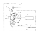
図1は、本実施例の電子写真画像形成装置の概略構成を示す断面図である。
図1において、電子写真画像形成装置Aは、像担持体(電子写真感光体)としての感光体ドラム1を有する。感光体ドラム1は、帯電手段としての帯電ローラ2により一様に接触帯電され、次いで、露光手段としての光学スキャナ3により画像情報に基づいた露光が行われ、感光体ドラム1上に静電潜像が形成される。この静電潜像はトナー(現像剤)により現像され、その結果、感光体ドラム1上にはトナー像が形成される。感光体ドラム1
上のトナー像は、転写手段としての転写ローラ7に電圧が印加されることによって、カセット6から転写位置へ搬送された記録材5に転写される。トナー像が転写された記録材5は、定着手段8により加熱加圧されて定着が行われる。
Example 1 will be described below.
(Outline of image forming apparatus)
FIG. 1 is a cross-sectional view showing a schematic configuration of the electrophotographic image forming apparatus of this embodiment.
In FIG. 1, an electrophotographic image forming apparatus A has a
The upper toner image is transferred to the recording material 5 conveyed from the
(プロセスカートリッジの構成)
プロセスカートリッジBは、感光体ドラム1と、感光体ドラム1に作用する少なくとも1つのプロセス手段を備えたものである。ここでプロセス手段は、帯電ローラ2、現像剤担持体としての現像スリーブ4、クリーニングブレード9等に相当する。
感光体ドラム1は、アルミシリンダ等の導電性基体上に感光層を有するもので、プロセスカートリッジBに回転自在に設けられている。帯電ローラ2は金属製芯金に弾性層を備えており、感光体ドラム1の表面に加圧接触して配設され、芯金に電圧が印加されることにより、感光体ドラム1の表面を一様に帯電する。
光学スキャナ3は半導体レーザからのレーザ光を感光体ドラム1上に収束させる光学系や高速回転するポリゴンミラー等を用いたもので、画像情報に応じた露光を感光体ドラム1上に行うことを可能にしたものである。露光により生じる感光体ドラム1表面の電位差によって静電潜像が形成される。
(Process cartridge configuration)
The process cartridge B includes the
The
The
現像スリーブ4は、感光体ドラム1に形成された静電潜像を可視化するためのトナーを担持するものである。現像スリーブ4は、アルミシリンダの表面が導電性材料によるコート、もしくはブラスト等により処理されており、現像スリーブ4表面には、現像剤規制部材等によって均一な厚みを持つ薄いトナー層が形成されている。現像スリーブ4に電圧が印加されることで、感光体ドラム1上の静電潜像との間で生じた電位差によりトナーが転移し、これにより画像情報に応じたトナー像が感光体ドラム1上に形成される。
クリーニングブレード9はウレタンゴム等で成形されており、感光体ドラム1の表面移動に対してカウンタ方向になるように当接配置されており、記録材5への転写後に感光体ドラム1上に残存するトナー等の異物をかきとる事が可能である。
The developing
The cleaning blade 9 is formed of urethane rubber or the like, and is disposed in contact with the surface movement of the
(現像スリーブユニットの構成)
次に、図2を用いて、現像スリーブ4まわりの構成について更に詳細に説明する。図2は、プロセスカートリッジB内に配置されている現像スリーブユニット40と感光体ドラムユニット10を示す概略断面図である。
感光体ドラムユニット10は、ドラムシリンダ11、ドラムギア12、ドラムフランジ13で構成されている。図1において感光体ドラム1として示されている部分はドラムシリンダ11に相当する。ドラムギア12及びドラムフランジ13は、ともにカシメや圧入等の方法によりドラムシリンダ11に一体化されている。ドラムギア12に対して駆動力が不図示のギアにより伝達されて、感光体ドラム1は回転する。
(Configuration of developing sleeve unit)
Next, the configuration around the developing
The
現像スリーブユニット40は、スリーブシリンダ41、スリーブフランジ42、マグネットローラ43、間隔(間隙)保持部材44,45、スリーブギア部材46、及び、支持部材47で構成されている。図1において現像スリーブ4として示されている部分は円筒状の回転部材としてのスリーブシリンダ41に相当する。
スリーブシリンダ41はスリーブフランジ42と圧入等の方法により一体化されている。スリーブフランジ42には、スリーブギア部材46に係合するDカット部が形成されており、スリーブギア部材46に伝達された駆動力によりスリーブシリンダ41が回転するように構成されている。
スリーブフランジ42と一体化されているスリーブシリンダ41は、軸方向(回転軸方向、長手方向)の一端側がスリーブギア部材46の先端部46aに配設された不図示の軸受けで支持されており、他端側が支持部材47により支持されている。このようにして、スリーブシリンダ41は回転可能に構成されている。支持部材47はプロセスカートリッジBの内部で回転しないように構成され、スリーブシリンダ41は支持部材47に対して
摺動するように構成されている。
The developing
The
The
マグネットローラ43は、支持部材47及びスリーブフランジ42によって支持されており、さらに、マグネットローラ43に形成されているDカット部が支持部材47に係合することによって、支持部材47に対して回転しないように構成されている。この結果、マグネットローラ43によって形成される磁束密度分布が、トナー循環や現像に対して有効に働く事が可能となる。
間隔保持部材44,45は、スリーブシリンダ41の軸方向の端部に配設されるとともに、ドラムシリンダ11の表面に当接するように構成されている。プロセスカートリッジB内では、感光体ドラムユニット10と現像スリーブユニット40とは互いに加圧されるように構成されている。そして、間隔保持部材44,45の厚みにより感光体ドラム1の表面と現像スリーブ4の表面との間隔が0.2〜0.4mm程度になるように設定されている。
The
The
支持部材47は導電性樹脂により成形されており、上述したスリーブシリンダ41及びマグネットローラ43の支持だけでなく、スリーブシリンダ41に対して現像バイアスの接点としての働きも有する。
The
(支持部材の構成)
次に、図3を用いて、支持部材47の構成について詳細に説明する。図3は、本実施例の支持部材47を示す概略斜視図である。
支持部材47は、スリーブシリンダ41を支持するための円筒形部分47aを有しており、円筒形部分47aの外周面は、でスリーブシリンダ41の内周面を周方向(回転方向)に摺動自在に支持している。また、円筒形部分47aには、その内部(内周側)に中空部47eが設けられており、さらに中空部47eに連通する開口(開口部)47b,47cが設けられている。ここで、開口47cは、中空部47eからスリーブシリンダ41の内周面に向けて開口している。また、開口47bは、スリーブシリンダ41の外部に向けて開口する外向開口部であって、中空部47eに連通して設けられた外向開口部に相当する。
(Configuration of support member)
Next, the configuration of the
The
また、円筒形部分47aのうち軸方向におけるスリーブシリンダ41側の端部の内周面には、マグネットローラ43のDカット部を受ける平面部47dが設けられている。
上述したように、支持部材47は現像スリーブ4への現像バイアスの供給を行う接点としての機能も持っている。具体的には、アセタール樹脂にカーボンを分散させて導電性も持たせて支持部材47を成形している。また、画像形成装置側の接点をこの支持部材47に当接させることで、画像形成装置に内蔵されている電源(不図示)の出力バイアスを現像スリーブ4に通電させている。
In addition, a
As described above, the
(現像スリーブユニットの組立方法)
次に、図4を用いて現像スリーブユニット40の組立て方法について説明する。図4は、現像スリーブユニット40の組立て方法について説明するための図であり、図4(a)はスリーブシリンダ41にスリーブフランジ42及びマグネットローラ43を組付ける方法について説明するための図である。図4(b)はスリーブフランジ42及びマグネットローラ43が組付いた状態のスリーブシリンダ41に、間隔保持部材44,45、スリーブギア部材46、支持部材47を組付ける方法について説明するための図である。
まず、スリーブフランジ42をスリーブシリンダ41における軸方向の右端部に圧入などの方法によって固定する。その後、マグネットローラ43をスリーブシリンダ41内部に挿入する(図4(a)参照)。この時、マグネットローラ43右端部の細軸部43aとスリーブフランジ42の内周面42aの摺動性を向上させるため、細軸部43aには潤滑油が塗布される。
(Development sleeve unit assembly method)
Next, a method for assembling the developing
First, the
図4(b)に示すように、上述したスリーブシリンダ41、スリーブフランジ42及びマグネットローラ43を組付けたものに対してさらに、間隔保持部材44,45、スリーブギア部材46、支持部材47が挿入される(組付けられる)。このとき、スリーブシリンダ41の右側には間隔保持部材44、スリーブギア部材46が、またスリーブシリンダ41の左側には間隔保持部材45、支持部材47が挿入される。また、スリーブシリンダ41の右側は間隔保持部材44、スリーブギア部材46の順で、またスリーブシリンダ41の左側は間隔保持部材45、支持部材47の順で、挿入される。組み立てられた現像スリーブユニット40は、不図示のプロセスカートリッジBの枠体にビス等の固定手段により固定される。
As shown in FIG. 4 (b), spacing
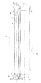
(潤滑剤の塗布(供給)方法)
次に上述のように組み立てられた現像スリーブユニット40のスリーブシリンダ41の内周面(摺動面)と、支持部材47の円筒形部分47aの外周面(摺動面)との間の摺動部の潤滑性(摺動性)を確保するための潤滑剤の塗布方法について図5を用いて説明する。図5は、不図示の台に置かれた現像スリーブユニット40に対して、潤滑剤塗布装置100のノズル100aの先端を、現像スリーブユニット40の支持部材47の開口47bから支持部材47の内部に挿入している様子を示す概略断面図である。ここで、潤滑剤塗布装置100は注射器状の手段でも良い。
ノズル100aの先端部を、支持部材47の開口47bより挿入し、中空部47e及び開口47cを介してスリーブシリンダ41の内周面に接近させる。ノズル100aの先端部がスリーブシリンダ41の内周面に対して、0.5〜1mmに接近した状態で、ノズル100aの先端部より潤滑剤としての導電グリスを吐出させることで、スリーブシリンダ41の内周面(摺動部)に導電グリスを塗布する。塗布する位置は、摺動する圧力が最も大きくなると予測される部分、例えば、軸方向で間隔保持部材45と感光体ドラム1との当接部位付近が望ましい。吐出中に、スリーブシリンダ41を回転させると、より効率的に摺動部に導電グリスを送り込むことが可能である。
(Lubricant application (supply) method)
Next, sliding between the inner peripheral surface (sliding surface) of the
The tip of the
(マグネットローラのリサイクル)
本実施例においては、マグネットローラ43がリサイクル可能に構成されている。上述したように現像スリーブユニット40において、支持部材47は、スリーブシリンダ41に対して固定されず、回転可能(摺動自在)に構成されている。このことで、スリーブシリンダ41に対して支持部材47を外す際の抵抗が小さくなり、容易にマグネットローラ43を取り出すことが可能となっている。
(Magnet roller recycling)
In this embodiment, the
以上説明したように、本実施例では、スリーブシリンダ41の内周面に向けて開口する開口47cから、スリーブシリンダ41と支持部材47との間の摺動部に導電グリスを供給している。このように本実施例では、スリーブシリンダ41と支持部材47とを組付けた後に、摺動部に導電グリスを塗布することができる。このことで、従来のようにスリーブシリンダと支持部材とを組付けることで、組付け前に塗布した導電グリスが移動してしまうようなことはなく、必要量の導電グリスをより確実に摺動部に供給することができる。これにより、摺動性をより向上させることが可能となる。また、従来のようにスリーブシリンダと支持部材とを組付けることで、組付け前に塗布した導電グリスが移動してスリーブシリンダ41の表面が導電グリスにより汚染されることを防止することができる。これにより、スリーブシリンダ41の表面に導電グリスが付着することによる画像弊害の発生を抑制することができる。
したがって、スリーブシリンダ41の表面が導電グリスにより汚染されることを防止しながら、支持部材47との間の摺動部に対して、より効率的に潤滑剤を塗布することが可能となる。さらには、支持部材47がスリーブシリンダ41に対する接点を兼ねる場合において、より良好な接触状態を得ることが可能となる。
As described above, in this embodiment, the conductive grease is supplied to the sliding portion between the
Therefore, the lubricant can be more efficiently applied to the sliding portion between the
(他の形態)
以下に、他の形態として、円筒状の回転部材としての感光体ドラム1と、感光体ドラム1における軸方向の一端側に設けられ感光体ドラム1を回転可能(摺動自在)に支持する支持部材200との間の摺動部に対して潤滑剤を供給する場合について説明する。図6は、感光体ドラム1と支持部材200との間の摺動部に対して潤滑剤の供給を行う方法を示した図である。
感光体ドラム1が円筒状の回転部材である場合においても、上記現像スリーブを用いて説明した場合と同様に、潤滑剤塗布装置100のノズル100aの先端部より導電グリスを吐出させて感光体ドラム1の内周面(摺動部)に塗布することができる。
(Other forms)
In the following, as another form, the
Even when the
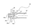
以下に、実施例2について説明する。図7,8は本実施例の支持部材48がスリーブシリンダ41に組付いた状態を示す概略断面図である。
支持部材48は、実施例1の支持部材同様、電子写真画像形成装置に備えられる円筒状の回転部材における軸方向の一端側の内周面を周方向(回転方向)に摺動自在に支持するものである。また、支持部材48と、円筒状の回転部材とが組付けられることで回転体ユニットが構成される。なお、本実施例の電子写真画像形成装置は、支持部材の構成以外は実質的に上述した実施例1の電子写真画像形成装置Aと同様の構成であり、同様の構成部分については同一の符号を付してその説明は省略する。
Example 2 will be described below. 7 and 8 are schematic sectional views showing a state in which the
The
図7に示すように、本実施例の支持部材48は、実施例1と同様にスリーブシリンダ41に組み込まれ、現像スリーブユニット40を構成している。支持部材48には、潤滑剤を一時蓄えるための一時容器部48aが設けられ、この部分に導電グリスが予め注入され蓄えられる(収容されている)。ここで、一時容器部48aは中空部に相当する。
一時容器部48aは、支持部材48の内部に設けられた空間であって、2つの開口(開口部)が設けられている。2つの開口のうち一方は、現像スリーブユニット40が組み立てられた場合に、スリーブシリンダ41の内周面に向けて開口する開口48dである。他方は、導電グリスが蓄えられた状態で、封止部材48bによって封止されている。
As shown in FIG. 7, the
The
本実施例の特徴として、支持部材48には、一時容器部48aに蓄えられている潤滑剤を押圧する押圧手段が設けられている。押圧手段は、封止部材48b、押し部材48e、及び、押し部材48eと封止部材48bとの間に配設されたバネ部材48cで構成されている。ここで、押し部材48eは、(支持部材48の外部から)押されることで変位する操作部材に相当する。また、封止部材48bは、押し部材48eが押され変位した場合に、一時容器部48a内(中空部内)の潤滑剤を押圧する押圧部材に相当する。
As a feature of the present embodiment, the supporting
押し部材48eには係止爪48e1が設けられており、係止爪48e1が支持部材48の内壁に設けられた凹部に係合することで、押し部材48eは支持部材48本体に係止されることとなる。支持部材48の凹部は、スリーブシリンダ41に組み込まれた場合におけるスリーブシリンダ41の軸方向の内側の凹部48g1と外側の凹部48g2との2箇所に設けられている。導電グリスが支持部材48の一時容器部48aに注入された状態であって、プロセスカートリッジBの組立て前の状態では、係止爪48e1は凹部48g2に係合している。このように本実施例では、支持部材48本体と押し部材48eとの間には、凹部48g1,48g2、係止爪48e1で構成される係止機構が設けられている。
The
プロセスカートリッジBの組立て時には、導電グリスが支持部材48の一時容器部48aに注入された状態で、現像スリーブユニット40を組立て、さらに、不図示の必要な部品を組付けプロセスカートリッジBとして完成させる。プロセスカートリッジBの完成後に、図8に示すように、押し部材48eを軸方向の内側に押し込み、係止爪48e1を奥
側(軸方向内側)の凹部48g1に係合する(引っかかる)ところまで押し込む。バネ部材48cは圧縮され、その結果、封止部材48bは奥側に向かう方向に押圧(加圧)される。これにより、封止部材48bによって、一時容器部48aに蓄えられている導電グリスも押圧(加圧)されるため、開口48dよりスリーブシリンダ41の内周面に導電グリスが供給される。このとき、スリーブシリンダ41を回転させれば、さらに効率的にスリーブシリンダ41の内周面に導電グリスを塗布することが可能となる。このようにして、本実施例においても、スリーブシリンダ41の内周面(摺動面)と、支持部材48の外周面(摺動面)との間の摺動部に、一時容器部48aから開口48dを介して導電グリスを塗布することが可能となる。
When the process cartridge B is assembled, the developing
本実施例によれば、実施例1で説明した効果に加えて次のような効果を得ることができる。すなわち、潤滑剤の量や、スリーブシリンダ41に対する軸方向における潤滑剤供給位置を、実施例1に比べて、より安定させることができ、これにより、より確実な摺動性、電気的導通性を得ることができる。
According to the present embodiment, in addition to the effects described in the first embodiment, the following effects can be obtained. That is, the amount of lubricant and the lubricant supply position in the axial direction with respect to the
ここで、押し部材48eを押し込むのはプロセスカートリッジBの組立て完成後である必要はなく、現像スリーブユニット40の組立後であればよい。そのため、プロセスカートリッジ組立工程において、潤滑剤塗布の時期を選べるため、工程全体の効率を考慮しながらの実施も可能となり、組立て効率の向上が可能となる。
また、本実施例では、封止部材48b、押し部材48e及びバネ部材48cにより押圧手段を構成しているが、これに限るものでない。すなわち、押圧手段は、一時容器部48a内の潤滑剤を押圧することで、開口48dを介して、スリーブシリンダ41の内周面と支持部材48の外周面との間の摺動部に潤滑剤を供給できるものであればよい。
また、感光体ドラム1が円筒状の回転部材である場合においても、上述したような、円筒状の回転部材としてスリーブシリンダ41を用いた場合に適用した支持部材と同様な支持部材を採用することができる。
なお、上述した実施例1,2では、円筒状の回転部材としてスリーブシリンダ41、感光体ドラム1を適用した場合について説明したが、円筒状の回転部材は、これらに限るものではない。電子写真画像形成装置に備えられる円筒状の回転部材において、支持部材がこの回転部材における軸方向の一端側の内周面を周方向に摺動自在に支持するように構成されているものであれば、本発明を好適に適用することができる。
Here, the pushing
In the present embodiment, the pressing member is configured by the sealing
Even when the
In the first and second embodiments, the case where the
A 電子写真画像形成装置 ; 41 スリーブシリンダ ; 47,48 支持部材
; 47c,48d 開口 ; 47e 中空部 ; 48a 一時容器部
A Electrophotographic image forming apparatus; 41 Sleeve cylinder; 47, 48 Support member; 47c, 48d Opening; 47e Hollow part; 48a Temporary container part
Claims (6)
中空部と、該中空部と連通して前記摺動部に対向する位置に設けられた第1開口部と、を有する前記支持部材を、前記回転部材の前記一端側に嵌合させる工程と、
前記中空部から前記第1開口部を介して、前記摺動部に向けて前記潤滑剤を供給する工程と、
を有することを特徴とする潤滑剤供給方法。 A cylindrical rotary members used in electrophotographic image forming apparatus, the inner peripheral surface of the rotation axis direction of the one end side of the rotating member to the sliding portion between the slidably supported to the support member, the lubricating A lubricant supply method for supplying an agent,
And the middle hollow portion, comprising the steps of: a first opening provided at a position opposed to the sliding portion in communication with said hollow portion, said support member having a fitting on said one end of said rotary member ,
Before SL and the hollow portion through the first opening, and the step of supplying the lubricant toward the sliding portion,
A method of supplying a lubricant, comprising:
中空部と、該中空部と連通して前記摺動部に対向する位置に設けられた第1開口部と、を有する前記支持部材に対して、前記中空部に前記潤滑剤を収容する工程と、
前記支持部材に設けられた前記中空部と連通する第2開口部を、封止部材を用いて封止する工程と、
前記支持部材を、前記回転部材の前記一端側に嵌合させる工程と、
前記封止部材を、前記中空部の中に向けて押し込むことで、前記摺動部に向けて前記潤滑剤を供給する工程と、
を有することを特徴とする潤滑剤供給方法。 Lubricating a sliding portion between a cylindrical rotating member used in an electrophotographic image forming apparatus and a supporting member that slidably supports an inner peripheral surface on one end side in the rotation axis direction of the rotating member. A lubricant supply method for supplying an agent,
A step of accommodating the lubricant in the hollow portion with respect to the support member having a hollow portion and a first opening provided at a position communicating with the hollow portion and facing the sliding portion; ,
Sealing the second opening communicating with the hollow portion provided in the support member using a sealing member;
Fitting the support member to the one end of the rotating member;
Supplying the lubricant toward the sliding portion by pushing the sealing member into the hollow portion; and
Or lubricants supplied how to characterized in that have a.
前記回転部材との摺動部に対向する位置に設けられ、前記摺動部に対して潤滑剤を供給するための第1開口部と、
該第1開口部と連通する中空部と、
該中空部と連通する第2開口部と、
を有することを特徴とする支持部材。 In support member for supporting freely sliding the inner peripheral surface of the rotation axis direction of the one end side of the cylindrical rotary members used in electrophotographic image forming apparatus,
A first opening provided at a position facing the sliding portion with the rotating member, for supplying a lubricant to the sliding portion;
A hollow portion communicating with the first opening ;
A second opening communicating with said hollow portion,
A support member comprising:
前記第2開口部を封止する封止部材を更に有し、
前記封止部材は、封止を行う第1位置と、該第1位置よりも前記中空部の中に向かった第2位置とに移動可能に構成されている
ことを特徴とする請求項3に記載の支持部材。 The hollow portion contains the lubricant,
A sealing member that seals the second opening;
The sealing member has a first position for sealing, to claim 3, characterized in that it is movable in the second position towards the inside of the hollow portion than the first position The support member as described.
円筒状の回転部材と、
該回転部材における回転軸方向の一端側の内周面を摺動自在に支持する支持部材と、
該支持部材における、前記回転部材との摺動部に対向する位置に設けられ、前記摺動部に対して潤滑剤を供給するための第1開口部と、
前記支持部材に設けられ、前記第1開口部と連通する中空部と、
前記支持部材に設けられ、前記中空部と連通する第2開口部と、
を有することを特徴とする回転体ユニット。 A rotating body unit provided in an electrophotographic image forming apparatus,
A cylindrical rotating member;
And supporting lifting member support the inner peripheral surface of the rotating shaft direction of the one end side of the rotary member freely sliding,
A first opening provided in the support member at a position facing the sliding portion with the rotating member, and for supplying a lubricant to the sliding portion;
A hollow portion provided in the support member and communicating with the first opening;
A second opening provided in the support member and communicating with the hollow portion;
A rotating body unit comprising:
前記第2開口部を封止する封止部材を更に有し、A sealing member that seals the second opening;
前記封止部材は、封止を行う第1位置と、該第1位置よりも前記中空部の中に向かった第2位置とに移動可能に構成されていることを特徴とする請求項5に記載の回転体ユニット。The said sealing member is comprised so that a movement to the 1st position which seals and the 2nd position which went in the said hollow part rather than this 1st position is characterized by the above-mentioned. The rotating body unit described.
Priority Applications (3)
| Application Number | Priority Date | Filing Date | Title |
|---|---|---|---|
| JP2010082634A JP5473727B2 (en) | 2010-03-31 | 2010-03-31 | Lubricant supply method, support member, and rotating body unit |
| US13/050,202 US8905908B2 (en) | 2010-03-31 | 2011-03-17 | Lubricant supplying method, supporting member and rotatable member unit |
| CN201110079332.XA CN102207721B (en) | 2010-03-31 | 2011-03-31 | Lubricant supplying method, supporting member and rotatable member unit |
Applications Claiming Priority (1)
| Application Number | Priority Date | Filing Date | Title |
|---|---|---|---|
| JP2010082634A JP5473727B2 (en) | 2010-03-31 | 2010-03-31 | Lubricant supply method, support member, and rotating body unit |
Publications (3)
| Publication Number | Publication Date |
|---|---|
| JP2011215327A JP2011215327A (en) | 2011-10-27 |
| JP2011215327A5 JP2011215327A5 (en) | 2013-04-25 |
| JP5473727B2 true JP5473727B2 (en) | 2014-04-16 |
Family
ID=44696604
Family Applications (1)
| Application Number | Title | Priority Date | Filing Date |
|---|---|---|---|
| JP2010082634A Expired - Fee Related JP5473727B2 (en) | 2010-03-31 | 2010-03-31 | Lubricant supply method, support member, and rotating body unit |
Country Status (3)
| Country | Link |
|---|---|
| US (1) | US8905908B2 (en) |
| JP (1) | JP5473727B2 (en) |
| CN (1) | CN102207721B (en) |
Families Citing this family (4)
| Publication number | Priority date | Publication date | Assignee | Title |
|---|---|---|---|---|
| CA2574122A1 (en) | 2004-07-21 | 2006-02-02 | Still River Systems, Inc. | A programmable radio frequency waveform generator for a synchrocyclotron |
| WO2014052721A1 (en) | 2012-09-28 | 2014-04-03 | Mevion Medical Systems, Inc. | Control system for a particle accelerator |
| EP2901823B1 (en) * | 2012-09-28 | 2021-12-08 | Mevion Medical Systems, Inc. | Controlling intensity of a particle beam |
| US10067461B2 (en) * | 2016-02-29 | 2018-09-04 | Canon Kabushiki Kaisha | Developing cartridge with a restricted portion that contacts a restricting portion of an image forming apparatus |
Family Cites Families (20)
| Publication number | Priority date | Publication date | Assignee | Title |
|---|---|---|---|---|
| US817683A (en) * | 1905-05-17 | 1906-04-10 | Michael H Whalen | Journal-box. |
| GB691420A (en) * | 1951-01-10 | 1953-05-13 | Glacier Co Ltd | Improvements in or relating to bearings |
| US3332536A (en) * | 1966-06-13 | 1967-07-25 | Rex Chainbelt Inc | Rotating shaft seal |
| CH450825A (en) * | 1966-12-23 | 1968-04-30 | Bbc Brown Boveri & Cie | Hydrostatic thrust bearing |
| NL6905357A (en) | 1969-04-05 | 1970-10-07 | ||
| US3746415A (en) * | 1971-08-05 | 1973-07-17 | Thomson Ind Inc | Self lubricating sleeve bearing |
| US4672894A (en) * | 1986-03-03 | 1987-06-16 | Hardin Philip J | High rotational speed autoreversing axially oscillating ink roller |
| JP3271997B2 (en) | 1990-07-13 | 2002-04-08 | キヤノン株式会社 | Process cartridge and image forming apparatus |
| JPH06130791A (en) * | 1992-10-14 | 1994-05-13 | Ricoh Co Ltd | Bearing device |
| TW290617B (en) * | 1993-10-19 | 1996-11-11 | Kiyomizu Rikuro | |
| JPH0822195A (en) | 1994-07-08 | 1996-01-23 | Canon Inc | Developing device and process cartridge |
| JP4048343B2 (en) * | 1999-07-14 | 2008-02-20 | 富士重工業株式会社 | Lubrication mechanism of centrifugal clutch |
| JP2001201940A (en) | 2000-01-14 | 2001-07-27 | Canon Inc | Developing device, process cartridge and image forming device |
| JP2002162830A (en) * | 2000-11-28 | 2002-06-07 | Hitachi Ltd | Developer unit for electrophotographic device |
| CN100462864C (en) | 2003-05-22 | 2009-02-18 | 三菱化学株式会社 | Light-sensitive body drum, method and device for assembling the drum, and image forming device using the drum |
| JP2005242333A (en) | 2004-01-30 | 2005-09-08 | Canon Inc | Image heating apparatus provided with flexible sleeve |
| TWM274468U (en) * | 2005-01-12 | 2005-09-01 | Mou-Kun Chen | Improved bearing oil-retaining structure |
| US20080317522A1 (en) | 2007-06-22 | 2008-12-25 | Jeffrey Allen Ardery | Fuser assembly having oil retention features |
| JP2010002578A (en) | 2008-06-19 | 2010-01-07 | Kyocera Mita Corp | Bearing structure, cleaning device equipped therewith, and image forming device |
| JP2010008884A (en) * | 2008-06-30 | 2010-01-14 | Kyocera Mita Corp | Developer stirring device and image forming apparatus provided therewith |
-
2010
- 2010-03-31 JP JP2010082634A patent/JP5473727B2/en not_active Expired - Fee Related
-
2011
- 2011-03-17 US US13/050,202 patent/US8905908B2/en not_active Expired - Fee Related
- 2011-03-31 CN CN201110079332.XA patent/CN102207721B/en not_active Expired - Fee Related
Also Published As
| Publication number | Publication date |
|---|---|
| CN102207721A (en) | 2011-10-05 |
| US8905908B2 (en) | 2014-12-09 |
| JP2011215327A (en) | 2011-10-27 |
| CN102207721B (en) | 2014-03-05 |
| US20110245054A1 (en) | 2011-10-06 |
Similar Documents
| Publication | Publication Date | Title |
|---|---|---|
| US8787794B2 (en) | Cartridge, image forming apparatus, and drum attaching method | |
| JP5473727B2 (en) | Lubricant supply method, support member, and rotating body unit | |
| EP3144737B1 (en) | Image forming apparatus | |
| US9098062B2 (en) | Process cartridge and image forming apparatus | |
| US10310412B2 (en) | Developing apparatus, cartridge, and image forming apparatus for suppressing developer leakage of a frame | |
| JPH06102754A (en) | Image forming device and developer regulating member | |
| JP2000075631A (en) | Developing device, developing cartridge and image forming device | |
| JP4779429B2 (en) | Developer processing apparatus and image forming apparatus | |
| JP2004170933A (en) | Image forming apparatus | |
| US6915091B2 (en) | Developing apparatus | |
| JP4656091B2 (en) | Developer and image forming apparatus | |
| JP2014122981A (en) | Developing device, process cartridge, and image forming apparatus | |
| JPH06308819A (en) | Sealing member, process cartridge using sealing member and image forming device | |
| JP2007058056A (en) | Developing apparatus, process cartridge, developing unit cartridge, and image forming apparatus | |
| JPH0713390A (en) | Seal member, process cartridge using seal member, and image forming device | |
| JP6672354B2 (en) | Developing device, cartridge and image forming device | |
| KR101753500B1 (en) | Developing unit and process cartridge | |
| JPH07219295A (en) | Process cartridge and image forming device | |
| JP3817540B2 (en) | Image forming apparatus and process cartridge | |
| JP2003050508A (en) | Developer carrier, developing device, process cartridge and image forming device | |
| JP2007164021A (en) | Developing device, process cartridge, and image forming apparatus | |
| JP2010191174A (en) | Image carrier drum, image forming apparatus, and process cartridge | |
| JP2013033147A (en) | Cleaning device and image forming apparatus using the same | |
| JP2000214681A (en) | Developing roll | |
| JP2015011196A (en) | Developing device, and image forming apparatus |
Legal Events
| Date | Code | Title | Description |
|---|---|---|---|
| A521 | Written amendment |
Free format text: JAPANESE INTERMEDIATE CODE: A523 Effective date: 20130305 |
|
| A621 | Written request for application examination |
Free format text: JAPANESE INTERMEDIATE CODE: A621 Effective date: 20130305 |
|
| TRDD | Decision of grant or rejection written | ||
| A01 | Written decision to grant a patent or to grant a registration (utility model) |
Free format text: JAPANESE INTERMEDIATE CODE: A01 Effective date: 20140107 |
|
| A61 | First payment of annual fees (during grant procedure) |
Free format text: JAPANESE INTERMEDIATE CODE: A61 Effective date: 20140204 |
|
| R151 | Written notification of patent or utility model registration |
Ref document number: 5473727 Country of ref document: JP Free format text: JAPANESE INTERMEDIATE CODE: R151 |
|
| LAPS | Cancellation because of no payment of annual fees |