JP5470051B2 - Note capture device - Google Patents
Note capture device Download PDFInfo
- Publication number
- JP5470051B2 JP5470051B2 JP2009550162A JP2009550162A JP5470051B2 JP 5470051 B2 JP5470051 B2 JP 5470051B2 JP 2009550162 A JP2009550162 A JP 2009550162A JP 2009550162 A JP2009550162 A JP 2009550162A JP 5470051 B2 JP5470051 B2 JP 5470051B2
- Authority
- JP
- Japan
- Prior art keywords
- image
- capture device
- note
- image capture
- planar image
- Prior art date
- Legal status (The legal status is an assumption and is not a legal conclusion. Google has not performed a legal analysis and makes no representation as to the accuracy of the status listed.)
- Active
Links
Images


Classifications
-
- G—PHYSICS
- G06—COMPUTING; CALCULATING OR COUNTING
- G06F—ELECTRIC DIGITAL DATA PROCESSING
- G06F3/00—Input arrangements for transferring data to be processed into a form capable of being handled by the computer; Output arrangements for transferring data from processing unit to output unit, e.g. interface arrangements
- G06F3/01—Input arrangements or combined input and output arrangements for interaction between user and computer
- G06F3/03—Arrangements for converting the position or the displacement of a member into a coded form
- G06F3/041—Digitisers, e.g. for touch screens or touch pads, characterised by the transducing means
- G06F3/042—Digitisers, e.g. for touch screens or touch pads, characterised by the transducing means by opto-electronic means
- G06F3/0425—Digitisers, e.g. for touch screens or touch pads, characterised by the transducing means by opto-electronic means using a single imaging device like a video camera for tracking the absolute position of a single or a plurality of objects with respect to an imaged reference surface, e.g. video camera imaging a display or a projection screen, a table or a wall surface, on which a computer generated image is displayed or projected
Description
ここで開示される典型的な実施形態は、情報を捕捉するために使用されるデジタル電子装置に関する。より詳しくは、ここで開示される典型的な実施形態は、手書き及び関係するメタデータを捕捉するために使用する装置に関する。 The exemplary embodiments disclosed herein relate to digital electronic devices used to capture information. More particularly, the exemplary embodiments disclosed herein relate to an apparatus used to capture handwriting and related metadata.
手書きのノートは、情報を記録するための簡便な方法として、記録された歴史において使用されてきた。紙を製造する技術及びペンや鉛筆のような筆記用具は、長年にわたって幾分変わったが、実際の手書きノートを書くための方法は、数千年の間、実質上変化していなかった。この事実は、情報を記録するこの形式の簡便さ及び有効性についての証拠である。 Handwritten notes have been used in recorded history as a convenient way to record information. While the technology for making paper and writing instruments such as pens and pencils have changed somewhat over the years, the method for writing actual handwritten notes has not changed substantially for thousands of years. This fact is evidence of the convenience and effectiveness of this form of recording information.
電子コンピュータの到来とともに、手書きノートを改良するための様々な試みが実行された。とりわけ、「パーソナルデジタルアシスタント(PDA)」及び「ペンコンピュータ」は、手書きを捕捉し、様々な組織的なサービスを提供するために開発された。 With the advent of electronic computers, various attempts were made to improve handwritten notes. Among other things, “Personal Digital Assistant (PDA)” and “Pen Computer” have been developed to capture handwriting and provide various organized services.
手書き認識は、情報を検索し、編集することが可能になる利益を得るために、しばしばPDA及びペンコンピュータに備えられる。 Handwriting recognition is often provided in PDAs and pen computers to gain the benefit of being able to retrieve and edit information.
手書き認識は、分かりやすい手書き入力を受け取るためのコンピュータの能力である。記載されたテキストのイメージは、光学スキャニング(光学式文字認識)によって紙から「オフライン」で感知され得る。代わりに、例えば、ペンコンピュータのスクリーン面によって、ペン先の動きが「オンライン」で感知され得る。 Handwriting recognition is the ability of a computer to receive easy-to-understand handwritten input. The described text image can be sensed “off-line” from paper by optical scanning. Alternatively, pen tip movement can be sensed "online", for example, by a screen surface of a pen computer.
手書き認識の初期の試みは、認識精度の問題に苦しめられた。一般に、認識アルゴリズムが人の読み手の文脈上の知覚を有さず、そしてそれ故、手書きの情報を捕捉する困難性を有する。人でさえ、時々、手書きを解釈する困難性を有する。 Early attempts at handwriting recognition suffered from recognition accuracy issues. In general, recognition algorithms do not have a contextual perception of a human reader and therefore have the difficulty of capturing handwritten information. Even people sometimes have difficulty interpreting handwriting.
Palmは、Graffiti(登録商標)認識システムに基づくPDAのシリーズを発売した。Graffiti(登録商標)は、それぞれのノートのためのペンのストロークのセットを定めることによってその利便性を改良した。これは、ストロークパターンの記憶が、ユーザのための学習曲線を増加させたとはいえ、間違った入力についての可能性を狭くした。 Palm has released a series of PDAs based on the Graffiti (R) recognition system. Graffiti® has improved its convenience by defining a set of pen strokes for each note. This narrowed the possibility of incorrect input, although memory of the stroke pattern increased the learning curve for the user.
近年、人が紙に書くことができ、結果として生じるテキストをデジタルで保存されるように、いくつかの試みが、テキストデジタル要素を含むインクペンを製造するために行われた。これらの製品の成功は、未だ定かではない。 In recent years, several attempts have been made to produce ink pens containing text digital elements so that humans can write on paper and the resulting text is stored digitally. The success of these products is not yet known.
ユーザがノートをとるとき、ユーザのノートの主題に長時間集中しているとき、ユーザが認識エラーを正す必要で邪魔され、又は、Graffiti(登録商標)のような手書きの新たな形式をうまく処理するために、リアルタイム手書き認識が、ユーザにとって不当な負担になることが明らかとなった。 When users take notes, when they are focused on the subject of the user's notes for a long time, they are disturbed by the need to correct recognition errors, or handle new forms of handwriting like Graffiti (R) well Therefore, it has become clear that real-time handwriting recognition is an unreasonable burden on the user.
紙に書くことの触感はまた、典型的なPDAまたはペンコンピュータを使用するときに、減少する。より身近な紙のパッドのパッド表面及び筆記具を安定させる身近なドラッグ以外に、硬く、劇的に少ない摩擦を有する面に表示されるものがある。ユーザは、ペンをそれ自体安定させることによって補わなければならない。このなじみのない手書きモードはまた、特別なノートの主題について書くときに、ユーザの考えのプロセスを邪魔する。 The feel of writing on paper is also reduced when using a typical PDA or pen computer. In addition to the pad surface of the more familiar paper pad and the familiar drag that stabilizes the writing instrument, there are those that are displayed on a hard, dramatically less friction surface. The user must make up by stabilizing the pen itself. This unfamiliar handwriting mode also interferes with the user's thought process when writing about special note subjects.
3Mによって発明され製造されたポストイットノートは、裏面の接着剤のある再付着ストリップを伴う1つの筆記用具であり、書類、コンピュータディスプレイその他に、ノートを一時的に取り付けるために設計されている。広範囲の色、形状、サイズが現在利用可能である一方、最も共通するポストイットノートのサイズは、3平方インチで、色においてはトレードマークのカナリア色である。 The post-it note, invented and manufactured by 3M, is one writing instrument with a redeposited strip with adhesive on the back, designed to temporarily attach notes to documents, computer displays, and so on. While a wide range of colors, shapes and sizes are currently available, the most common post-it note size is 3 square inches, in color the trademark canary color.
ポストイットノートは、リマインダ、電話番号、電話メッセージ等を記録するための情報ノートに関する便利な媒体として出現した。それらは、各ノートが容易に取り付けられ、そしてマークや残渣を残すことなく取り除かれるようにする低タック接着ストリップを特色とする。ポストイットノートの用法は、ユビキタスである。この種のノート取りは、ノート取りのときに高い標準の利便性を示す。ユーザは、ノートパッドに簡単に書き、ノートを取り除き、そして、その後にリマインダとして目立つ場所に置き、または、注釈等として書類上に置く。 Post-it notes have emerged as a convenient medium for information notes for recording reminders, phone numbers, phone messages, and the like. They feature a low tack adhesive strip that allows each note to be easily attached and removed without leaving marks or debris. The usage of post-it notes is ubiquitous. This type of note taking shows a high standard of convenience when taking notes. The user simply writes on the notepad, removes the note, and then places it in a prominent place as a reminder or places it on a document as an annotation or the like.
従来技術の電子装置は、ポストイットノートを書くときに達成されるノート取りの利便性のレベルを達成するのに失敗している。必要なのは、ポストイットノートの利便を、伝達性、検索、及び編集に関する電子捕捉の利益に結合する手段である。不幸にも、従来技術は、そのようないかなる解決をも提供しないという理由で制限される。 Prior art electronic devices have failed to achieve the level of note taking convenience achieved when writing post-it notes. What is needed is a means to combine the convenience of post-it notes with the benefits of electronic capture for transferability, search, and editing. Unfortunately, the prior art is limited because it does not provide any such solution.
これらの及び他の従来技術の制限は、以下の記載を読み、いくつかの図表を研究することで、当業者にとって明白となるであろう。 These and other prior art limitations will become apparent to those skilled in the art upon reading the following description and studying some of the diagrams.
本出願は、アメリカ合衆国の仮特許出願60/890,180「ノート捕捉装置」の利益を求め、これにより参照によって組み込まれる。
This application seeks the benefit of US
特定の限定されない例示的な実施形態は、筆記面、筆記面を見るためのカメラ、及び前記筆記面又は例えばビジネスカードの面を含む他の様々な代わりの面のイメージを捕捉するための電子回路を含むノート捕捉装置を提供する。例えば、その面に関する傾斜カメラ角度を矯正し得る様々なイメージ変形が考えられる。イメージの可読性を高め、又は、印、ロゴ等を加えるための他の変形もまた考えられる。 Certain non-limiting exemplary embodiments include a writing surface, a camera for viewing the writing surface, and an electronic circuit for capturing images of the writing surface or other various alternative surfaces including, for example, a business card surface. A note capture device is provided. For example, various image deformations that can correct the tilt camera angle with respect to the surface are conceivable. Other variations to increase the readability of the image or add marks, logos, etc. are also conceivable.
特定の例示的な実施形態は、ノートを書くことの完了の自動検出を提供し、そして、検出において、完了したノートの捕捉を促す。特定の実施形態は、ノート取りの完了を検出するための様々なセンサを採用する。他の実施形態は、ボタンクリックの使用を通じてこの検出を実行する。さらに、他の実施形態は、イメージ分析を通じてこの検出を実行する。これらの実施形態の様々な組み合わせが考えられる。 Certain exemplary embodiments provide for automatic detection of the completion of writing a note and prompt the capture of the completed note upon detection. Certain embodiments employ various sensors for detecting the completion of note taking. Other embodiments perform this detection through the use of button clicks. Furthermore, other embodiments perform this detection through image analysis. Various combinations of these embodiments are possible.
特に例示的な実施形態及び組み合わせにおいて、捕捉されたイメージは、内部に保存され、パーソナルコンピュータ、携帯電話、サーバ等の外部装置に電子的に送信される。ノート捕捉装置と外部装置との間の通信のモードは、装置に直接又は間接に接続されるケーブル、又は、装置を直接又は間接に接続するワイヤレス接続を含み得る。通信が、磁気メディア、フラッシュメモリ装置、及び他の不揮発性記憶装置及び媒体のような取り外し可能な媒体の使用を通じて生じ得るということがさらに考えられる。1つの装置から他の1つの装置へとデータを送信する、他の共通に使用される通信の方法もまた考えられる。 In particular exemplary embodiments and combinations, captured images are stored internally and electronically transmitted to external devices such as personal computers, cell phones, servers, and the like. The mode of communication between the note capture device and the external device may include a cable connected directly or indirectly to the device, or a wireless connection connecting the device directly or indirectly. It is further contemplated that communication can occur through the use of removable media such as magnetic media, flash memory devices, and other non-volatile storage devices and media. Other commonly used communication methods that transmit data from one device to another are also conceivable.
特定の実施形態において、様々な送り先に捕捉されたノートをルーティングする目的のためのノート捕捉装置と相互に通信すること、及び、例えば、限定されることなく、SMTP、FTP、SFTP、HTTP、HTTPS、Windows、MacOS、Linux、CE Mobile、Palm OS、Symbian、OSesに基づくJava、といったものを含む様々な商業的に利用可能なオペレーティングシステム、を含む様々なプロトコルのような様々な通信モードに導くこと、をユーザに許容するために、スクリーンが提供される。 In certain embodiments, communicating with a note capture device for the purpose of routing notes captured to various destinations and, for example, without limitation, SMTP, FTP, SFTP, HTTP, HTTPS To various communication modes such as various protocols, including various commercially available operating systems, including Windows, MacOS, Linux, CE Mobile, Palm OS, Symbian, Java based on OSes, etc. , A screen is provided.
様々なオペレーションのモードにおいて、手書き認識ソフトウェアが、全体又は部分における捕捉されたノートを表示するテキストをつくるために使用される。そのような認識されたテキストは、ノートに関連するイメージ情報を添付でき、又は、前記イメージ情報の代わりに使用され得る。 In various modes of operation, handwriting recognition software is used to create text that displays captured notes in whole or in part. Such recognized text can attach image information associated with the note or can be used in place of the image information.
ノートに関連するイメージ情報は、ストローク情報、圧縮される等に変形されることを含む様々な方法において変形され得る。 Image information associated with a note can be transformed in a variety of ways, including being transformed into stroke information, compressed, etc.
特定の他の例示的な実施形態は、ベースイメージ平面を定めるレスト面及び、前記ベースイメージ平面に対して傾斜する光学軸を定める固体カメラ装置を含む平面イメージ捕捉装置を含み得る。ここで使用されるように、固体カメラは、一般に、半導体処理技術から作られるカメラを参照し、そしてそれ故、1以上のレンズを必然的に含むものではない。しかしながら、様々のタイプの他のカメラが、おそらく要求される実施形態とともに使用され得る。 Certain other exemplary embodiments may include a planar image capture device that includes a rest surface that defines a base image plane and a solid state camera device that defines an optical axis that is inclined with respect to the base image plane. As used herein, solid state cameras generally refer to cameras made from semiconductor processing technology and therefore do not necessarily include one or more lenses. However, various types of other cameras could possibly be used with the required embodiment.
もう1つの例示的な実施形態は、平面イメージ捕捉装置を有する平面イメージ捕捉システムを含み得る。平面イメージ捕捉装置は、ベースイメージ平面を定めるレスト面と、前記イメージ平面に対して傾斜する光学軸を定める固定カメラ装置とを有し、前記カメラ装置は、前記固体カメラ装置から少なくとも約2.5インチ以上約7.5インチ以下で広がる被写界深度を伴う固定された光学焦点を有する。加えて、システムは、少なくとも捕捉装置からイメージ情報を受信することが可能な平面イメージ捕捉装置に接続される計算装置を含み得る。
Another exemplary embodiment may include a planar image capture system having a planar image capture device. The planar image capture device includes a rest surface that defines a base image plane and a fixed camera device that defines an optical axis that is inclined with respect to the image plane, the camera device being at least about 2.5 from the solid-state camera device. It has a fixed optical focus with a depth of field that extends from inches to less than about 7.5 inches. In addition, the system may include a computing device connected to the planar image capture device capable of receiving at least image information from the capture device.
さらにもう1つの例示的な実施形態は、イメージ情報を与える方法を提供し得る。その方法は、ベースイメージ平面に対して傾斜する光学軸、および前記固定カメラから少なくとも約2.5インチ以上約7.5インチ以下で広がる被写界深度を伴う固定焦点を有する固体カメラ装置を向けることを含む。その方法はまた、前記固体カメラ装置でイメージデータを捕捉すること、及び、少なくとも部分的にイメージデータをデジタルメモリに保存することを含み得る。
Yet another exemplary embodiment may provide a method for providing image information. The method directs a solid-state camera device having an optical axis that is inclined with respect to a base image plane, and a fixed focus with a depth of field that extends from the fixed camera at least about 2.5 inches to about 7.5 inches. Including that. The method may also include capturing image data with the solid state camera device and storing the image data at least partially in digital memory.
もう1つの例示的な実施形態は、方法を実行するためのプロセッサによって実行のためにそこに保存されるコンピュータ可読インストラクションを有するコンピュータ使用可能媒体を提供する。その方法は、ベースイメージ平面に対して傾斜する光学軸、及び、少なくとも約2.5インチから約7.5インチの間で広がる被写界深度を伴う固定焦点を有する固体カメラ装置を向けること、固体カメラでイメージデータを捕捉すること、及びイメージデータを、デジタルメモリ内に少なくとも部分的に保存すること、を含む。
Another exemplary embodiment provides a computer usable medium having computer readable instructions stored thereon for execution by a processor for performing the method. The method directs an optical axis inclined with respect to the base image plane, and a solid camera device having a fixed focal with depth of field extending between about 2.5 inches to about 7.5 inches even with no less Capturing image data with a solid-state camera and storing the image data at least partially in digital memory.
さらに他の例示的な実施形態は、ネットワーク及び平面イメージ捕捉装置を含むイメージ捕捉及び送信システムを提供する。平面イメージ捕捉装置は、ベースイメージ平面を定めるレスト面、ベースイメージ平面に対して傾斜する光学軸を定める固体カメラ装置を含み、前記カメラ装置は、少なくとも約2.5インチ以上約7.5インチ以下で広がる被写界深度を伴う固定光学焦点を有する。平面イメージ捕捉装置は、ネットワークに接続され、前記イメージ情報を、ネットワークを通じてもう1つの装置に送信するように操作可能である。
Yet another exemplary embodiment provides an image capture and transmission system that includes a network and a planar image capture device. Planar image capture device, rest surface defining a base image plane, comprises a solid camera device defining an optical axis that is inclined relative to the base image plane, the camera device, even without less than about 2.5 inches to about 7.5 It has a fixed optical focus with a depth of field that extends below inches. The planar image capture device is connected to a network and is operable to transmit the image information to another device over the network.
ここで開示される、これらの及び他の実施形態及び有利性及び他の特徴は、以下の記載を読むこと、及びいくつかの図表を研究することで、当業者に明白になるであろう。 These and other embodiments and advantages and other features disclosed herein will become apparent to those of ordinary skill in the art upon reading the following description and studying some of the diagrams.
様々な例示的な実施形態の特定の特徴は、捕捉されたノート、それらに関係するメタデータ、認識結果等を、ビュー、ブラウズ、共有、検索及び編集するアプリケーションソフトウェアを提供する。様々な例示的な実施形態は、ユーザの「デスクトップ」又は様々なアプリケーションウィンドウに関連し得るヒューマンインターフェイスソフトウェアを含む。 Certain features of the various exemplary embodiments provide application software for viewing, browsing, sharing, searching and editing captured notes, their associated metadata, recognition results, and the like. Various exemplary embodiments include human interface software that may be associated with a user's “desktop” or various application windows.
いくつかの例示的な実施形態は、今、図面を参照して記載され、同様な要素は、同様な参照番号とともに与えられる。例示的な実施形態は、例示を意図し、発明を限定するものではない。 Several exemplary embodiments will now be described with reference to the drawings, wherein like elements are provided with like reference numerals. The exemplary embodiments are intended to be illustrative and not limiting of the invention.
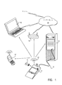
図1は、ノート捕捉装置2と、このノート捕捉装置2が通信を行う他の装置とを示すハイレベル図である。例えば、ノート捕捉装置2は、例示的な実施形態において、USBケーブル6を経由してパーソナルコンピュータ4と通信し得る。ノート捕捉装置2が他の手段を経由してパーソナルコンピュータ4と通信し得るということもまた考えられる。捕捉装置2は、例示的な実施形態におけるバッテリ8又は、例えば110ボルトで運転する交流ウォールソケットを電源として駆動する電源アダプタ10(図示せず)のような他の手段によって駆動され得る。ワイヤレス通信サブシステム12が、様々な実施形態において、パーソナルコンピュータ4、ワイヤレスインターネットルータ14、ラップトップコンピュータ16、及び携帯電話17のような様々なワイヤレス装置と通信するためのノート捕捉装置2によって使用される。ノート捕捉装置2が通信するこれらの様々な装置は、インターネット18に選択的に接続される。ノート捕捉装置2の目的は、ポストイットノートに含まれるような手書きの情報を捕捉するための直感的な方法を提供することである。捕捉された手書き情報は、その後、パーソナルコンピュータ4、ワイヤレスインターネットルータ14、ラップトップコンピュータ16、又は携帯電話17を含む、ノート捕捉装置2が通信し得る様々な装置の1つに送信される。特定の例示的な実施形態において、捕捉された情報は、前記装置に保存され、又はインターネット18を経由して、インターネット18に接続される、サーバ20(図示せず)又は他のパーソナルコンピュータ4等のような様々な電子装置に転送される。
FIG. 1 is a high level diagram showing a
図2は、図1のノート捕捉装置2のより顕著な詳細を示す。ノート捕捉装置2に含まれるのは、パームレスト22(レスト面としても参照される)、コピーボタン24、トップページが、除去可能な筆記面となり得るノートパッド26、ファンクションランプ28、カメラポスト30、及びカメラヘッド32、である。手のひらがパームレスト22に接触するそれぞれの領域が実質的にパームレスト22の全体の面積よりも小さいことから、パームレスト22は、実質的に連続である。他の要素が内部に存在する一方、これらの要素は、様々なサブセット、スーパーセット、及びコンビネーションにおいて、特定の例示的な実施形態におけるノート捕捉装置2のためのヒューマンインターフェイスとしての役割を果たす。 図示されない様々なセンサ及び電子機器が、ノート捕捉装置2の機能性を与えるために必要とされ、そして、より顕著な詳細において次に議論されるであろう。ノート捕捉装置2を使用しているとき、ユーザは、ペンや鉛筆のような筆記用具を簡単にとり、ノートパッドに書き留める。例示的な実施形態において、ノートパッド26への手書きの完了は、ユーザがコピーボタン24を押すこと、または、前記手書きの完了を示す他の手動若しくは自動のトリガメカニズムによって信号化される。ノートパッド26の一番上の記載におけるイメージは、USB6、ワイヤレス通信サブシステム12、又は他の手段を経由して外部装置に送信される。このとき送信されるそのイメージが、コピーボタン24の押圧に先んじて捕捉されることに留意すべきである。換言すれば、コピーボタン24の押圧は、イメージが送信され、そして、カメラヘッド32が作動し、イメージを得るということを示す合図として使用されても良いかどうかということを示す。カメラヘッド32は、連続モード又は、コピーボタン24の近傍の作動モードのクリックにおいて、作動可能である。加えて、参照番号23は、一般に、細長くされたベースアセンブリを示す。
FIG. 2 shows more prominent details of the
パッド26は、いくつかの実施形態において、紙の各シートが、弱い、再使用可能な接着成分によってもう1つのシートに保持されるタイプのものであり得る。
The
限定されないある実施形態において、平面イメージ捕捉装置は、ベースイメージ平面を定めるレスト面、及びベースイメージ平面に対して傾斜する光学軸を定める固定カメラ装置を含む。固体カメラはまた、少なくとも約2.5インチ以上約7.5インチ以下で広がる被写界深度を有する。一般的に言えば、被写界深度は、面のイメージが、カメラ装置から見えるものとしてかなり明らかである距離である。また一般的に言えば、被写界深度は、平面イメージ捕捉装置が組み付けられたときに、固定範囲に換算される。
In one non-limiting embodiment, the planar image capture device includes a rest surface that defines a base image plane and a fixed camera device that defines an optical axis that is tilted with respect to the base image plane. Solid camera also has a depth of field extending up to about 2.5 inches or more to about 7.5 inches even with no low. Generally speaking, the depth of field is the distance at which the image of the surface is quite obvious as seen from the camera device. Generally speaking, the depth of field is converted into a fixed range when the planar image capturing device is assembled.
図3は、図1及び図2のノート捕捉装置2のより顕著な詳細を示す。ノートパッド26は、ノートパッドレスト34に残り、ユーザの手書き面を提供する。コピーボタン24は、ユーザに、ノートが完了したことを示すことを許容するために備えられる。コピーボタン24下のコピーボタンマイクロスイッチ36は、コピーボタン24の動きを、ノートの完了を示すために使用される電気的な信号に変換されるように使用される。ある実施形態において、コピーボタンマイクロスイッチ36は、プリント回路基板38に取り付けられる。パームレスト22は、ある実施形態において、プリント回路基板38に取り付けられるパームレストマイクロスイッチ36に接触している。プロセッサ42は、プリント回路基板38に取り付けられ、ノート捕捉装置2の様々な機能を実行するための計算能力を与える。カメラヘッド32は、構造支持要素30に取り付けられ、カメラケーブル44を経由してプリント回路基板38に接続される。構造支持要素30は、ポスト又はディスプレイとして定められ得る。ページ除去検出器46は、ある限定されない実施形態において、ノートの除去の検出を補助するために備えられる。この種の検出はまた、カメラヘッド32によって得られるイメージの解析を通じて、受動的な手段によって達成され得る。ノート捕捉装置2の様々な実施形態において、センサの数と種類は、非常に多くなり得る。ページ除去検出器46は、ある例示的な実施形態において、ノートパッド26の一番上のノートに対する継続的な物理的接触を維持するために設けられるスプリングである。ページ除去検出器46が、ノートの除去を示す動きを検出するとき、電気的信号が発生し、プリント回路基板38に伝達される。この信号は、パームレストマイクロスイッチ36、コピーボタンマイクロスイッチ40、ページ除去検出器46、様々なセンサからの様々な信号と同様に、カメラヘッド32によって得られるイメージと同様に、いつノートが完了し、捕捉されるべきかの決定を補助するために、全て一緒に使用される。ノートが捕捉されるとき、ノートのイメージを含む信号は、パーソナルコンピュータ4、ワイヤレスインターネットルータ14、ラップトップコンピュータ16、又は携帯電話17のような外部装置に送信される。イメージの通信は、ワイヤレス通信サブシステム12(図示せず)を含む様々な方法において、又は、USBコネクタ48を経由してプリント回路基板38に接続されるUSBケーブル6のような物理的に接続される手段によって、生じうる。USBケーブル6はしかし、多くの可能な物理的接続である。イーサネットケーブル等を代わりに含む。
FIG. 3 shows more prominent details of the
図2及び他の図はまた、実質的に平坦な面を含むベースイメージ平面27を示す。ベースイメージ平面27は、一般的に、ノートパッド26の四角形以外の様々な形状のものが可能で、そして、連続的である必要がないことについて留意されるべきである。加えて、図3Bに示されるような垂直軸29が、ベースイメージ平面27によって定められる。ここで使用される、「垂直な被写界深度」は、例えば、認識及び/又はシステムの他の目的のために、イメージが十分な焦点及び/又は解像度である、カメラヘッド32によって検出されるイメージがシステムによって使用のために十分に分析される垂直軸29に対して実質的に平行な被写界深度で定義される。
FIG. 2 and other figures also show a
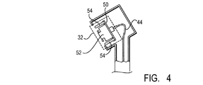
図4は、図2及び図3のカメラヘッド32のより顕著な詳細を示す。カメラヘッド32は、ある例示的な実施形態において、カメラプリント回路基板50、カメラアセンブリ52、及びLED54を含む。カメラアセンブリ52は、レンズ、及び、カメラセンサからカメラケーブル44を越えて、他の要素、特に、プリント回路基板38に取り付けられるプロセッサ42に一連のイメージを送信することができるカメラセンサ装置を含む。LED54は、ノート捕捉装置2及び、より詳細には、ノートパッド26の手書き面が、様々な光の照明条件で照らされるように、光を与える。図4において示されるカメラヘッド32の構成は、ある例示的な実施形態において、限定されない方法において解釈される。
FIG. 4 shows more prominent details of the
図5は、操作の様々なモードを検出するためのさらなるセンサ機器を伴う捕捉装置2を示す。特に、この実施形態において、ノートパッドレスト34は、ノートパッド26に対する圧力の適用が、手書き動作が生じていることを示すプロセッサ42に、プリント回路基板38を経由して伝搬され、電気的信号を生ずるように、圧力感知式である。接近センサ54はまた、ノートパッド26上に物理的に現れることを示す信号を与えるために含まれる。接近センサ54は、同様に、プリント回路基板38を経由して、電気的信号をプロセッサ42に伝搬する。既述のように、パームレスト22は、手書き操作が、プロセッサ42に対して生じる信号を与えるために、圧力感知式である。ここで記述される様々なセンサの出力は、ノートパッド26によって与えられる手書き面を変換するビューの領域を有するカメラヘッド32から得られるイメージ情報に結合される。ノートパッド26を直接覆っているものではないことから、カメラヘッド32のビューが傾斜しているということが留意されるべきである。構造支持要素30の高さは、得られたイメージデータがノートの適したイメージに矯正され得るように、ノートパッド26の適切なビューを与えるのに十分な高さである必要がある。
FIG. 5 shows the
図6は、カメラヘッド32のビューの領域のより顕著な詳細を示す。ここで示されるように、望ましい限定されない実施形態において、カメラヘッド32は、ノートパッド26の手書き面の中心に向けられる。パームレスト22に近いノートパッド26の部分は、大きな距離で見え、それ故、ノートパッド26の中心に関係するイメージの部分よりも、結果のイメージにおいて、より低い解像度を使用する。同様に、カメラヘッドに最も近いイメージの部分は、ノートパッド26の中心に関係するイメージの部分よりも、より高い解像度を使用する。
FIG. 6 shows more prominent details of the area of view of the
図7は、コピーボタン24のより顕著な詳細を示す。コピーボタン24の表面における凹みは、例示的な実施形態において、ペン、鉛筆又は他の筆記具が、プリント回路基板38に取り付けられるコピーボタンマイクロスイッチ36に直接物理的に接触するコピーボタン24から滑り落ちることなしに、容易にボタンを押すことができるように備えられる。
FIG. 7 shows more prominent details of the
図8は、例示的な実施形態において、ワイヤレス通信サブシステム12を含むノート捕捉装置2を示す。ワイヤレス通信サブシステム12は、プリント回路基板38に取り付けられる回路(図示せず)に結合されるノート捕捉装置2に対して内部的又は外部的になり得るアンテナとして部分的に設けられる。様々な通信プロトコルがワイヤレス通信サブシステム12とともに使用され得る。Blue Tooth、ワイヤレスLANプロトコル、携帯電話プロトコル等のようなプロトコルは、当業者によく知られている。様々な代替の実施形態は、IR等を含む。加えて、GPS信号を受信する機器もまた備えられ得る。GPS機器は、ノート捕捉装置2の位置を決定するために使用され、そしてそれ故、イメージに関連するメタデータとしてのイメージ情報とともに位置情報が保存され得る。これは、特定のノートを位置づけることを試みているユーザを後で助け得る。ユーザは、本能的に、努力なしに日付の大体の概算と同様にノートを書くときに、彼らがどこにいるかを覚えようとする。ここで開示されるノート捕捉装置は、特許請求の範囲内において、ここで開示される技術の小さな及び大きなアプリケーションに適応する範囲で、大きく変化し得るということに留意すべきである。
FIG. 8 illustrates a
図9は、ノート捕捉装置2の例示的な実施形態を示し、手書き面の特別に示された領域は、ノートの配置に関する特定の意味を有する。特定の領域56及び58は、この例において、ユーザがこの領域を、ペンや鉛筆等のような筆記具で押したときに、ユーザの定められた機能を実行するために与えられる。特定の領域56又は58における、ペンダウンの検出は、カメラヘッド32によって得られたイメージのイメージ解析によって、又は、特定の領域56及び58の下のマイクロスイッチのような様々なセンサを備えることによって、実行され得ることに留意すべきである。これらの実施形態に加えて、遮られる光線のような、様々な他のセンシング技術が使用され得る。特定の領域56及び58の配置は、例示的のみであり、多くの他の構成が可能である。特定の領域56及び58に関連する意味は、ユーザがプログラムでき、特定の、所定のユーザに対して捕捉されたノートをメールすること、ノートを、例えばサーバ20に組み込まれたウェブサイト(図示せず)上のアルバムに配置すること、所定のFAX番号にFAXを送ること等のような、様々な機能を含み得る。
FIG. 9 shows an exemplary embodiment of the
図10は、きれいなイメージが得られるということを保証する助けとなる捕捉処理に関して使用され得るLCDディスプレイスクリーン60を含むノート捕捉装置2の例示的な実施形態を示す。LCDディスプレイスクリーン60は、コピーボタン24を押して捕捉されるノートをユーザが見ることができるように、ユーザに対するフィードバックを提供するために使用され得る。また、LCDディスプレイスクリーン60は、ノート捕捉装置2のためのヒューマンインターフェイスとして使用され、そして、ペンや指が、ノート捕捉装置2の操作に影響する様々なソフトキー及び捕捉されたノートの配置と影響し合うように使用されるために、タッチスクリーン能力を付加的に含み得る。この例示的な実施形態において、構造支持要素30は、LCDディスプレイスクリーン60を収容するように広げられ、そして、カメラヘッド32は、広げられた支持要素30の一番上に取り付けられる。この実施形態において、ワイヤレス通信サブシステム12の部分は、他の実施形態としての構造支持要素30内に収容され得る。構造支持要素30はまた、いくつかの実施形態において、イメージを投影できる、要素30に支持される光要素を含み得る。さらにもう1つの実施形態において、イメージを処理することが、ノート捕捉装置2内で生じ得る。
FIG. 10 illustrates an exemplary embodiment of a
図3,5,6及び7を参照し、図11は、図3,5,6,及び7のプリント回路基板38に具体化される回路のブロック図である。プリント回路基板38の様々な要素は、バス62、プロセッサ42、揮発性記憶装置64、不揮発性記憶装置66、リードオンリーメモリ68、カメラIO70、及び他のIOである。デジタルメモリもまた、図11の構成に含まれる。他のI/O72は、デジタルメモリ、及び他のメモリ及び保存装置からのデータを、外部の装置又はネットワークに転送可能な通信ポートを含み得る。通信ポートは、配線され又は無配線であり得る。これらの様々なプリント回路基板38の電気要素は、ノート捕捉装置2内の埋め込まれたコンピュータとして、ノート捕捉、ユーザインターフェイス、及び通信の様々な機能を提供するように作動する。プロセッサ42は、バス62に接続され、ノート捕捉装置2の様々な機能のための主な計算能力を提供する。揮発性記憶装置64は、プロセッサ42内に具体化される様々な処理のための一時的な保存を含み得る。不揮発性記憶装置66は、フラッシュメモリ、又はハードディスクのような様々な保存サブシステムを含み得る。代わりの実施形態は、CD−ROM、フラッシュカード等のような様々なリムーバブルメディアを含み得る。換言すれば、当業者に知られる様々な不揮発性記憶サブシステムが、不揮発性記憶装置66を補い、またはそれに置き換えられるために使用され得る。特定の限定されない実施形態において、ノート捕捉装置2によって捕捉される1以上のノートが不揮発性記憶装置66に保存され、そして、その後、接続されている様々な装置にアップロードされる。リードオンリーメモリ68は、起動におけるプロセッサ42のためのOSレベルインストラクションを含むように備えられ、そしてまた、ユーザインターフェイス、捕捉、及び通信を実行するノート捕捉装置2上で動く処理の全体又は部分を含むプロセッサ42のための様々なライブラリ機能を与える。リードオンリーメモリ68は、プログラム可能であることに留意すべきである。カメラIO70は、ある例示的な実施形態において、携帯電話内に備えられるようなカメラに関連する電気要素を含み得る。様々な代替の実施形態は、光出力に関するカメラヘッド内にLEDを制御し、又は、LEDを作動、停止させる能力を含み得る。付加的な実施形態は、例えば、セキュリティ機能等を実行するための部屋又は他の環境をパンすることができるように、カメラの角度を変えるサーボ機構を含み得る。それ故、カメラIO70は、カメラヘッド32からイメージを得るだけでなく、様々なその操作の特徴を制御するために使用される。イメージ解像度等と同様に、ズーム及びフォーカスは、全てカメラIO70によって潜在的に制御される。他のIO72は、ノート捕捉装置2に関連する様々なセンサ及びマイクロスイッチに対するIOを与える。加えて、他のIO72は、例えば、キーボード、又はポインティング装置、又は、LCDディスプレイスクリーン60のような出力装置に対するIOを与え得る。付加的な例示的な実施形態は、そのタッチスクリーンの実施形態において、LCDディスプレイスクリーン60に関連するIOを与える。他のIO72はまた、例えば、ノート捕捉装置2の操作状況、通信状況、捕捉状況を表示するように使用され得るファンクションランプ28のような様々なLEDを制御するために使用され得る。他のIO72は、マイクロホン又はGPS機器を伴うインターフェイスに対して使用され得る。同様に、他のIO72の例示的な実施形態は、ワイヤレス通信サブシステム12、USBコネクタ48、及び他の通信モードを経由して通信を提供する。
Referring to FIGS. 3, 5, 6 and 7, FIG. 11 is a block diagram of circuitry embodied on the printed
ある実施例において、得られたイメージのアンチキーストーンイメージ処理が実行され、ROM68のようなメモリによって支援される。
In one embodiment, anti-keystone image processing of the resulting image is performed and supported by a memory such as
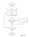
図12は、ノート捕捉装置2上、より詳細には、プリント回路基板38の様々な要素、特にプロセッサ42や関連するメモリ上を動く捕捉処理を示すフローチャートである。これは、ある操作モードの例に過ぎず、限定されない例によって与えられる。図12の操作のためのコードは、リードオンリーメモリ68や不揮発性記憶装置66内で具体化され、又は、パーソナルコンピュータ4、ラップトップコンピュータ16、あるいはノート捕捉装置2が携帯電話や、サーバ20のようなインターネット18上のサーバと通信し得る他の装置のような外部ソースからダウンロードされ得る。オペレーションは、オペレーション74において始まり、プロセスが初期化されるオペレーション76に続く。ノート捕捉装置2の様々なセンサと同様に、カメラヘッド32から得られるイメージをモニタするために必要とされる様々なバッファが、このときに初期化される。この点で、制御は、様々な入力が読まれるオペレーション78に移る。特定の実施形態において、イメージは、カメラヘッド32から継続的に得られ、そして、他の実施形態において、カメラヘッド32からのデータは、現在のプロセスによって特別に要求されるまで得られない。イメージが継続的に得られた場合、それは、どのイメージのフレームが捕捉されるべきかを決定するのを助けるために使用され得る。ある実施形態において、イメージが得られ、他のセンサは、どのイメージがノートとして捕捉されるべきかを決定するために必要とされない。このポイントで、オペレーション80は、イメージが捕捉されるべきか否かを決定する。これは、例えば、他の様々なセンサ及びカメラヘッド32によって得られるイメージに加えて、コピーボタンマイクロスイッチ36によって得られる信号のような様々なセンサ入力を試験することによって実行される。ある低コストの実施形態において、イメージを捕捉するタイミングを決定するために分析され得るカメラ入力以外、いかなるセンサも必要とされない。イメージが捕捉されるべきことがオペレーション80において決定された場合、制御は、オペレーション82に移り、ここでシングルイメージが捕捉される。捕捉の方式は、カメラヘッド32から又は、以前に保存されたイメージバッファから、シングルイメージを得ることである。いずれにしても、捕捉されるイメージは、ノート捕捉装置2と通信する既述の装置の1つを経由して、パーソナルコンピュータ4、ラップトップコンピュータ16、形態電話、又はサーバ20のような外部装置に送信される。ワイヤレスインターネットルータ14もまた、イメージを捕捉するために、サーバ20のようなインターネット上の様々な装置と通信するために使用され得る。オペレーション82の完了で、制御は、図12のオペレーションが完了されたかどうかを決定するオペレーション84に通じる。もし、オペレーション80において、イメージを捕捉すべきでないということが決定された場合、制御は、同様に、図12のオペレーションが完了されたか否かを決定するオペレーション84に移る。もし、図12のオペレーションが完了されたことがオペレーション84で決定された場合、制御はその後、オペレーションを終了するオペレーション86に移る。ノート捕捉装置2内での図12のオペレーションの実行に対する代替が、単に、イメージやセンサ入力のようなテレメトリをパーソナルコンピュータ4のような外部装置に送信し、その後、前記外部装置内で図12のオペレーションを実行すること、であることに留意すべきである。さらに、外部装置からノート捕捉装置2にメッセージを送信することによって様々なハードウェア要素を制御することも可能である。換言すれば、ここで記述される様々なプロセスは、様々な装置で具体化され得る。ある例示的な実施形態において、ノート捕捉装置は、内蔵の又は取り付けられるカメラを伴う携帯電話内で具体化され又は併合され得る。
FIG. 12 is a flowchart illustrating a capture process that runs on the
図13,14及び15は、図12のオペレーションの特定の実施形態のある特徴を、より詳細に記述するタイムラインの部分を示す。特定の例示的な実施形態において、捕捉するか否かの決定は、ユーザがコピーボタン24を押したことを検出することと同じくらい簡単であり、付加的な例示的な実施形態は、図12に記載される様々なセンサのモニタリングを含む。図13は、時間内に4つのモーメントを、そして、様々なセンサ入力を、それらの入力から得られる特定の情報と同様に表示する。タイムラインの第1のフレームは、ブランクイメージを示す。このとき、パームレストセンサは、何も検出せず、しかも、接近センサ、ページ除去センサも何も検出しない。このイメージが第1のイメージであり、比較することがないので、そのイメージマッチはネガティブである。同様に、イメージ一致はネガティブである。イメージがブランクであることが容易に検出されるので、イメージブランクは、ポジティブであり、インクがなく、そして、ユーザの手及びペンは、ビューの領域内にはない。ペンダウンセンサはまた、現在の手書き動作がないことを示す。フレーム2は、フレーム1と同じようにブランクイメージを示す。再び、ユーザの動作がなく、そして、それ故、パームレスト、接近、及びページ除去のようなセンサが全てネガティブである。しかしながら、このイメージが前のイメージと同一であるので、イメージマッチ及びイメージ一致が両方ともポジティブである。イメージブランクは、フレーム2のイメージがブランクであることを示すポジティブであり、そして、ペンダウンは、ユーザがノートパッド26上の記載に現在関係していないということを示すネガティブである。フレーム3において、ユーザは、ペンや鉛筆のような筆記具でノートパッド26上に書くことを始めた。完了された手書きの部分は、筆記具それ自体であるものとしてフレーム3において見ることができる。パームレスト22に関するパームレストセンサは、パームレストマイクロスイッチ40がパームレスト22上の圧力を検出することを示すように作動する。接近センサ54は、手や筆記具のような対象の接近を検出し、そしてそれ故、接近の表示もまたポジティブである。ページ除去センサは、ページの除去を検出しない。現在のイメージフレーム3がフレーム2における前のイメージとマッチしないことから、イメージマッチ決定はネガティブである。いくつかの手書きが現れるので、イメージは、もはやネガティブではない。ペンダウン表示は、ペンの圧力がペンダウンセンサを作動させるポジティブ表示である。今、タイムラインのフレーム4において、ユーザがこの手書き操作を実行し続けたことを、より多くの手書きが表す。パームレスト22及びパームレストマイクロスイッチ40に関連するパームレストセンサは、ユーザの手のひらがパームレスト22上で残っていることを示すポジティブである。同様に、接近センサ54は、ユーザの手又は筆記具の出現を検出する。ページ除去センサは、ページの除去を検出しない。イメージマッチ及びイメージ一致は、このイメージが前のイメージと異なることを示すネガティブである。イメージブランクは、ビューにおいて手書き及び筆記具の部分を有するので、このイメージがブランクでないことを示すネガティブである。ペンダウン表示は、圧力がノートパッド26、そしてそれ故、この実施形態において圧力センサを含むノートパッドレスト34に作用することを示すポジティブである。
13, 14 and 15 show portions of a timeline that describe in more detail certain features of a particular embodiment of the operation of FIG. In certain exemplary embodiments, the determination of whether to capture is as simple as detecting that the user has pressed the
今、図14に変わって、フレーム5は、手書きを含み、筆記具又はユーザの手の部分を含まないノートを示す。パームレスト表示は、圧力が現在、パームレスト22に作用しておらず、そしてそれ故、パームレストマイクロスイッチ40が休止していることを示すネガティブである。接近センサは、ユーザの手がノートパッドに接触していない一方、接近センサがそれを検出し続けることを生じさせるために、それが十分に近いことを示す。ページ除去センサ46は、ユーザがノートパッド26からノートを取り除くことを試みていないことを示すネガティブである。イメージマッチは、このイメージが、所定の許容範囲内の前のイメージと同じでないということを示すネガティブである。特定の許容範囲内で、微妙な変化についてイメージを比較し、マッチを示すために十分同じであるイメージを認証するための方法は、当業者によく知られている。イメージ一致表示は、このイメージがどのような前のイメージとも一致してないこと示すネガティブである。イメージブランク表示は、このイメージが、ブランクでないこと、およびその上に手書きを有することから、ネガティブである。ペンダウン表示は、圧力が現在ノートパッド26に作用しておらず、そしてそれ故、この実施形態において、圧力センサを含むノートパッドレスト34上で検出されないことを示すネガティブである。フレーム6は、実質的に前のイメージと同一であるイメージを示す。照明状態、及びカメラヘッド32内で具体化されるようなカメラセンサ内において、光子を収集することに固有な不完全さのために、ある微妙な変化が現れ得ることに留意すべきである。フレーム6において、パームレスト表示が、ユーザの手が現在パームレストセンサ22上で休息しておらず、そしてそれ故、パームレストマイクロスイッチ40が圧力を検出していないことを示すネガティブであるのに対し、接近表示は、ユーザの手がノート捕捉装置2に接近していることを示すポジティブである。ページ除去表示は、この場合ネガティブである。イメージマッチは、このイメージがマッチを示すための前のイメージに十分近いものであることを示すポジティブである。イメージ一致は、前のイメージ5が現れた手書きの全ての部分が、イメージ6内に現れることを示すポジティブである。もし、付加的なインクがイメージ6で見えたとき、イメージ一致は、未だポジティブである。それ故、イメージマッチとイメージ一致との間の相違は、イメージ一致が後のイメージにおいて付加的なインクにイメージマッチが寛容であるものである一方、イメージマッチが後のイメージにおける付加的なインクに寛容でないものであるということである。イメージブランクは、この例において、イメージがブランクでなく、手書きを含むことを示すネガティブである。ペンダウン表示は、現在ノートパッド26に作用する圧力がなく、そしてそれ故、この実施形態において、圧力センサを含むノートパッドレスト34に対する圧力がないことを示すネガティブである。
Now turning to FIG. 14, frame 5 shows a note that contains handwriting and does not include a writing instrument or part of the user's hand. The palm rest display is negative indicating that no pressure is currently acting on the
フレーム7は、付加的な手書きが生じ、そして、筆記具が再びイメージ内に部分的に見えることを示す。パームレスト表示は、ユーザのパームが現在パームレストセンサ22に圧力を作用させ、そしてそれ故、パームレストマイクロスイッチ40が作動されることを示すポジティブである。接近センサ54は、ノート捕捉装置2に接近するユーザの手の出現を検出する。ページ除去検出器46は、ユーザがページを除去することを試みていないことを表示する休止である。前のイメージが見えないのに対して、イメージマッチ表示器は、この場合において、付加的な手書きが生じ、そして、筆記具が現在イメージ内に見えるという事実によってネガティブである。イメージ一致は、同様に、筆記具がイメージ内に出現するために、ネガティブである。イメージブランクは、この場合、筆記具とある手書きが両方イメージ内に出現するために、ネガティブである。ペンダウン表示は、ユーザが現在、筆記具で圧力をノートパッド26に及ぼし、そしてそれ故、圧力が、この実施形態において、圧力センサを含むノートパッドレスト34に対して作用することを示すポジティブである。フレーム8は、筆記具がイメージから除去され、加えられた手書きを示す。パームレスト表示は、圧力が現在パームレスト22に作用しておらず、そしてそれ故、パームレストマイクロスイッチ40が休止していることから、ネガティブである。接近センサ46は、同様にユーザの手の出現を検出しない。ページ除去センサ46は、休止しており、そしてページ除去表示はネガティブである。イメージマッチは、現在のイメージにおいて休止であるのに対し、この例において、筆記具が前のイメージにおいて現れているので、ネガティブである。イメージ一致は、この例において、このイメージが、ある付加的なインクと同様に、フレーム5及び6において現れるインクの全てを含むため、ポジティブである。イメージブランク表示は、このイメージがあるインクを含むことから、ネガティブである。ペンダウンは、この例において、ユーザがノートパッド26に圧力を及ぼしていないことを示すネガティブである。
Frame 7 indicates that additional handwriting has occurred and that the writing instrument is again partially visible in the image. The palm rest display is positive indicating that the user's palm is currently exerting pressure on the
図15は、フレーム8の完了した手書きが見え、筆記具が現れていないフレーム9を示す。パームレスト表示は、ユーザの手がパームレスト22に圧力を及ぼしておらず、そしてそれ故、パームレストマイクロスイッチ40が休止であることを示すネガティブである。近接表示は、接近センサ54によって示されるように、ユーザの手がノート捕捉装置2に近くにあるということを示すポジティブである。ページ除去センサは、ユーザがノートパッド26からノートを取り除くことを試みておらず、そしてそれ故、ページ除去表示がネガティブであるということを示す。イメージマッチ表示は、許容範囲内で、このイメージが前のイメージにマッチすることを示すポジティブである。また、イメージ一致は、フレーム9のイメージが前のフレーム5,6及び8のイメージに一致することを示すポジティブである。イメージブランク表示は、イメージ9があるインクを含むので、ネガティブである。ペンダウン表示は、ユーザが現在ノートパッド26に書いておらず、そしてそれ故、ノートパッドレスト34への圧力を生じていることを示すネガティブである。フレーム10は、手書きに従うイメージに現れるユーザの親指を示す。パームレスト表示は、ユーザの手が現在パームレスト22に圧力を及ぼしており、そしてそれ故、パームレストマイクロスイッチ40を作動したことを示すポジティブである。近接表示は、ユーザの手が、ユーザの手を感知できるように、接近センサ54に十分近いことを示すポジティブである。ページ除去表示は、ユーザが未だノートパッド26からノートを取り除いていないことから、ネガティブである。イメージマッチは、ユーザの親指がフレームに入っていることから、ネガティブであり、そして、同様に、イメージ一致は、このイメージに前のイメージが一致するものがないことから、ネガティブである。イメージブランクは、フレームが手書き及びユーザの親指の部分を含むことから、ネガティブである。ペンダウンは、現在ノートパッド26に及ぼす圧力がないことから、ネガティブである。フレーム11は、ノートパッド26からノートを剥がすユーザを示す。パームレスト表示は、現在パームレスト22に圧力が作用していないことを示すネガティブである。接近センサ54は、ユーザの手の出現を検知し、そしてそれ故、近接表示はポジティブである。ページ除去センサは、ユーザがノートパッド26からノートを現在除去していることを示すポジティブである。ユーザがノート上に手書き操作を完了したことを示すことから、ページ除去表示の出現は、重要である。このフレームにおいて、ユーザの親指がイメージ内に見え、そして、ノートが剥がされることから、イメージマッチ表示はネガティブである。同様に、イメージ一致表示は、ネガティブである。イメージブランクは、ユーザの手及びノートのエッジが見えることから、ネガティブである。ペンダウンは、圧力が現在ノートパッド26に作用していないことを示すネガティブである。フレーム12は、ブランクイメージを含む。パームレスト表示は、ユーザが現在、彼の手でパームレスト22に圧力を及ぼしていないことを示すネガティブである。近接表示は、接近センサ54が現在ユーザの手の出現を検出していないことを示すネガティブである。ページ除去センサは、ユーザが現在ノートを除去していないことを示すネガティブである。イメージマッチは、このイメージが、ページが除去されてからとられた前のイメージと一致しないことを示すネガティブである。イメージブランクは、このイメージがブランクであることを示すポジティブである。ペンダウンは、圧力がノートパッド26に作用していないことを示すネガティブである。
FIG. 15 shows a frame 9 in which the completed handwriting of the frame 8 can be seen and no writing instrument has appeared. The palm rest display is negative indicating that the user's hand is not exerting pressure on the
図12,13,14及び15を参照し、図12のオペレーションは、ここで例として記述される様々な実施形態の形式をとり得る。これらの例は、限定されない方法において解釈される。例えば、図13,14および15の様々なフレーム1から12は、図12のオペレーション78が様々な入力をサンプリングする、時間内に考えられる例であり得る。様々な入力は、その後、オペレーション80で分析され、そして、さらにオペレーション82で処理されるように、バッファされる。イメージが捕捉されるものであることを決定するオペレーション80は、例えば、ページ除去センサについてのポジティブ表示によってトリガされる。これは、捕捉するタイミングを決定する1つの方法にすぎないことが強調されるべきである。他の例示的な実施形態は、捕捉ボタン24が押圧されることの検出、そして、その代わりとして、イメージそれ自体以外に、センサやボタンを必要としない実施形態、を含む。様々なセンサ及びボタン及びイメージの組み合わせもまた使用され得る。図12のオペレーション80が捕捉するときを決定したとき、制御は、イメージの捕捉を、例えば、パーソナルコンピュータ4、ラップトップコンピュータ16、携帯電話17、又はサーバ20のような外部装置に誘導する図12のオペレーション82に移る。代わりに、外部装置又は外部装置に物理的にロードされるリムーバブルメディアの使用を通じてアンロードされるために、捕捉されたイメージは、フラッシュメモリ、のような不揮発性記憶媒体にバッファされる。図12のオペレーション82は、外部装置又はカメラヘッド32に対してイメージの捕捉を実行するが、捕捉されるイメージは、カメラヘッド32によってとられた最も新しいイメージである必要はなく、むしろ、最も新しい安定したイメージであるということに留意すべきである。特定の実施形態において、イメージが安定し、そして、ペンダウンのような様々なセンサが筆記具の出現を検出しないということが要求される。これは、例えば、安定し、かつ、動作が発生していない、筆記具又は他の外来のオフジェクトの部分を含むイメージの不測の捕捉を防止するであろう。特定の実施形態において、最も新しい安定したイメージは、時間帯全体にわたって、様々な前のイメージと一致する。代わりの実施形態において、図12のオペレーション82は、カメラヘッド32から、単に最も新しい利用可能なイメージをとる。この種の捕捉は、ユーザが例えば、コピーボタン24をクリックしたときに、適している。特定の実施形態において、ノートデータ及び関連するメタデータを保護するために暗号化が使用され得る。ある実施形態において、権限を有するサーバ又は適切なプライベートキーを有する他の受け手によって操作されない限り、データが使用できないようにすべく、非対称暗号化アルゴリズムが、データを暗号化するために使用されるであろう。このアプローチは、特注で製造されることなしに、各ノート捕捉装置に対してパブリックキーがつくられることから、容易な製造の有利性を有する。これは、プライベートキーを使用して復号化する、サーバや他の装置に届くまで、データ送信中に、データが理解できなくなることから、データがコンテンツの分配を制御するために集中的に制御されるサービスを可能にする。特定の実施形態において、パブリックキーは、ノート捕捉装置2に対して定期的にアップデートされる。他の暗号化技術が、ノート捕捉装置ごとの独自のキーを可能にする。対称暗号化アルゴリズムもまた考えられる。特定の実施形態において、暗号化は集中的に制御されず、むしろ、ユーザが、個別基準においてユーザのノートのセキュリティを保護するために必要とされるキーをつくり、又は得るということを容易にする。ユーザは、例えば、複数のキーを有し、そして、暗号化及び復号化を手動で又は自動的に実行するためのキーから選択することができる。
With reference to FIGS. 12, 13, 14 and 15, the operations of FIG. 12 may take the form of various embodiments described herein by way of example. These examples are to be interpreted in a non-limiting manner. For example, the various frames 1-12 of FIGS. 13, 14, and 15 may be possible examples in time where
図16は、図12の処理に関連するどのイメージが捕捉されるかを決定するためのハイレベルソフトウェアによって使用され得るハイレベル「イメージタイムライン」を達成するために、カメラセンサからのデータを処理する「データ抽象化」技術を採用するための代わりの実施形態を示す図である。当業者によく知られるものとして、データ抽象化は、データセットの変形された「ビュー」を発展させること(カメラヘッドからのイメージストリームのような)を含む。次の変形は、低レベルの機能性を提供するための、より低いレベルの「ビュー」より高いレベルの「ビュー」として発達され得る。 FIG. 16 processes data from camera sensors to achieve a high level “image timeline” that can be used by high level software to determine which images associated with the process of FIG. 12 are captured. FIG. 6 illustrates an alternative embodiment for employing the “data abstraction” technique. As is well known to those skilled in the art, data abstraction involves developing a transformed “view” of a dataset (such as an image stream from a camera head). The next variant may be developed as a higher level “view” than a lower level “view” to provide a lower level of functionality.
イメージストリームは、特定の実施形態において、より新しい部分の余地をつくるために捨てられる不必要な部分とともに、ページングバッファを循環的に消費する。 The image stream, in certain embodiments, consumes the paging buffer cyclically, along with unnecessary portions that are discarded to make room for newer portions.
多くの組み合わせが当業者に明白になる一方、そのようなデータ抽象化技術の例が図16に示される。最も低いレベルのイメージシーケンス200は、センサから得られる生のイメージを示す。特定の実施形態において、イメージは、カメラ角度がカメラヘッドや手書き面の並置に応じて変化し得ることから、ビューワに対して傾いて現れ得る。変形されたイメージシーケンス220は、イメージシーケンス220が今、直交イメージのシリーズとして見られ得るように、幾何補正を実行する、変形されたイメージシーケンスを提供する。フィルタ処理されたイメージシーケンス240は、例えば、変形されたイメージシーケンス220によって提供され、捨てられるための材料を得る同じ直交イメージを提供し得る。望まれない材料を含むように、イメージを分類するための基準は、特定のアプリケーションに応じて大きく変化するであろう。特定の限定されない例示的な実施形態において、背景色及びインク色以外の色を含むイメージは、望まれないイメージを含むものとして分類されるであろう。インク色の決定は、背景色でない色に対して安定させるピクセルから得られ得る。フレッシュトーンを含むイメージの検出及び排除のような他の方法が、移動中のオブジェクト等の認識を含む多くの方法として可能である。これらの実施形態は例によって与えられ、限定される方法において解釈されるべきではない。イメージタイムライン260は、この例において、タイムインデックスによってアクセス可能なフィルタされたイメージシーケンスのビューを提供する。これは、多くの可能な例にすぎない。イメージタイムラインを使用することで、最も新しい安定したブランクのないイメージが、例えば、ブランクイメージを見分ける上で選択され得る。最も新しい安定したブランクのないイメージは、この限定されない例示的な実施形態において、捕捉するためのイメージとして選択され得る。
While many combinations will be apparent to those skilled in the art, an example of such a data abstraction technique is shown in FIG. The lowest
図17は、ノート捕捉装置2によって捕捉されたノートと連動して使用されるアプリケーションソフトウェアのオペレーションを示すフローチャートである。このアプリケーションソフトウェアが、例えば、ノート捕捉装置2それ自体と同様に、パーソナルコンピュータ、携帯電話、サーバ、ラップトップを含む様々な装置上で、様々な形式に具体化され得るということに留意すべきである。
FIG. 17 is a flowchart showing the operation of application software used in conjunction with the notes captured by the
オペレーションは、オペレーション280で始まり、オペレーション282に続き、バッファが割り当てられ、そして初期化され、そして、アプリケーション、ユーザインタフェ−ス要素、及び捕捉されたノートを含むデータベース等を表示する、オブジェクトのインスタンスが作成される。その後、オペレーション284において、データベースが、表示されるべきノートについて問い合わせられる。オペレーション286は、その表示に備えてノートの幾何的なレイアウトを行う。その後、オペレーション288において、ノートがユーザに表示される。イベントループオペレーション290は、その後、ユーザの動作に関係するイベント、および図12のオペレーションのような他のオペレーションとの通信を処理するためにイベントループに入る。イベントループ290の完了で、オペレーション292においてオペレーションが終結する。
The operation begins at
図18は、図17のイベントループ290の望ましいオペレーションのより顕著な詳細を示すフローチャートである。オペレーションは、オペレーション294において始まり、イベント列内に利用可能なイベントがあるかどうかを決定するオペレーション296に続く。この決定オペレーションは、イベントが利用可能になるまで、実行のカレントスレッドをブロックする割り込み駆動のオペレーションを実行する、条件文としてここに示される。多くの変化した実行は、当業者に明白である。もし、イベントが利用可能であると決定された場合、ハンドルイベントオペレーション298は、イベントを処理する。一旦、イベントが処理されると、制御は、その後、決定オペレーション300に移る。もし、利用可能なイベントがないと決定された場合、制御は、オペレーション300に移る。オペレーション300は、イベントループオペレーション290が完了したかどうかを決定する。例えば、それは、以前に処理されたユーザイベントによって、パワーダウンオペレーションが初期化されたかどうか、又はアプリケーション終了オペレーションが初期化されたかどうか、を決定する。オペレーション300において、イベントループオペレーション290が完了したことが決定された場合、制御は、オペレーションを終結するオペレーション302に移る。もし、他方、決定オペレーション300が、イベントループオペレーション290が完了していないと決定した場合、制御はオペレーションを継続するオペレーション296に移る。
FIG. 18 is a flowchart illustrating more significant details of the desired operation of the
図19は、図18の望ましいハンドルイベントオペレーション298のより顕著な詳細を示すフローチャートである。オペレーションは、オペレーション304で始まり、イベント列からイベントを得るオペレーション306に続く。
FIG. 19 is a flowchart illustrating more significant details of the preferred
その後、決定オペレーション308において、イベントがマウスイベントかどうかの決定がなされる。もし、イベントがマウスイベントであると決定された場合、制御は、現在受信が示されているオブジェクトインスタンスに対してさらにディスパッチすることによってマウスイベントを処理するオペレーション310に移る。これは、一般に、マウスイベントの座標を決定し、それをその座標に位置するGUIオブジェクトに対してディスパッチすることによってなされる。この種のディスパッチは、当業者によく知られている。このイベントの処理において、オブジェクトは、インスタンス変数、バッファ等、及びこのイベントの処理に関係する様々なタスクを実行する他のオブジェクトに対する信号を修正し得る。オペレーション310の完了で、制御は、オペレーション298を終結するオペレーション324に移る。もし、他方で、オペレーション308において、イベントがマウスイベントでないことが決定された場合、制御はその後、オペレーション312に移る。
Thereafter, in
その後、決定オペレーション312において、イベントが通信イベントであるかどうかに関する決定がなされる。もし、イベントが通信イベントであると決定された場合、制御は、現在受信を示しているオブジェクトインスタンスに対してさらにディスパッチすることによってマウスイベントを処理するオペレーション314に移る。これは、一般に、通信イベントを試験すること、及び、イベントに含まれ、又は通信バッファに関連するアドレス指定情報と同様に、通信の種類に基づいてディスパッチすることによってなされる。この種のディスパッチは、当業者によく知られている。通信イベントの1つの例は、ノート捕捉装置2によって捕捉されたノートを受け取ることである。そのようなイベントを処理するために、ノートが受け取られ、不揮発性記憶装置に集められ、そしてその後、ある例示的な実施形態において、データベースインサートオペレーションが実行される。多くのノートのデータベースの中にそのノートを配置するための手段として、後でテキストが調べられるようにすべく、ノートイメージからテキストが得られるように認証ソフトウェアが選択的に使用され得る。
Thereafter, in
通信イベントの処理において、オブジェクトは、インスタンス変数、バッファ等、及びこのイベントの処理に関係する様々なサブタスクを実行するための他のオブジェクトに対する信号を修正し得る。加えて、通信イベントの処理は、しばしば、存在している実行のスレッド、特に、手書き認識のような時間を消費するタスクに関して、起動し、通信することを含む。オペレーション314の完了で、制御は、オペレーション298を終結するオペレーション324に移る。もし、他方で、イベントが通信イベントでないと決定された場合、制御は、その後オペレーション316に移される。
In processing communication events, an object may modify instance variables, buffers, etc., and signals to other objects to perform various subtasks related to processing this event. In addition, processing of communication events often involves invoking and communicating with respect to existing threads of execution, particularly time-consuming tasks such as handwriting recognition. Upon completion of
その後、決定オペレーション316において、イベントがキーイベントであるかどうかについての決定がなされる。もし、イベントがキーイベントであると決定された場合、制御は、現在、受け取りを辞退しているオブジェクトインスタンスに対してさらにディスパッチすることによってマウスイベントを処理するオペレーション318に移る。これは一般に、GUIオブジェクトが「フォーカス」、最も新しく「クリック」されたオブジェクトに関連する表示、を現在有する決定によってなされる。この種のディスパッチは、当業者によく知られている。このイベントの処理において、オブジェクトは、インスタンス変数、バッファ等、及び、このイベントの処理に関係する様々なタスクを実行するための他のオブジェクトに対する信号を修正し得る。オペレーション318の完了で、制御は、オペレーション298を終結するオペレーション324に移る。もし、他方で、イベントがキーイベントでないと決定された場合には、制御は、その後オペレーション320に移される。
Thereafter, in
その後、決定オペレーション320において、イベントがもう1つの他のイベントであるかどうかについての決定がなされる。もし、イベントがもう1つのイベントであると決定された場合、制御は、現在、受け取りを示しているオブジェクトインスタンスに対してさらにディスパッチすることによってマウスイベントを処理するオペレーション322に移る。例えば、イベントは、回収されるべきノートを含む周辺の装置への1つのメディアの挿入を含む。様々な組み合わせが当業者に明白である。このイベントの処理において、オブジェクトは、インスタンス変数、バッファ等、及びこのイベントの処理に関係する様々なタスクを実行するための他のオブジェクトに対する信号を修正し得る。オペレーション322の完了で、制御は、オペレーション298を終結するオペレーション324に移る。もし、他方で、イベントがもう1つのイベントでないと決定された場合、制御はその後、オペレーション324に移される。
Thereafter, in
特定の限定されない例示的な実施形態は、手書き面、手書き面を見るように取り付けられるカメラ、及び前記手書き面のイメージを捕捉する電気回路、又は、例えば、ビジネスカードの面、を含む様々な代わりの面を含むノート捕捉装置を提供する。例えば、その面に関連する傾斜カメラ角度を矯正し得る様々なイメージ変形が考えられる。イメージの画質を高め、又は印、ロゴ等を加えるための他の変形もまた考えられる。他の情報もまた、特定のユーザを特定するようなデータを証明するためのデジタル署名等のようなイメージデータに関連し得る。 Certain non-limiting exemplary embodiments include various alternatives including a handwritten surface, a camera attached to view the handwritten surface, and an electrical circuit that captures an image of the handwritten surface, or a business card surface, for example. A note capturing device including the above-described surface is provided. For example, various image deformations that can correct the tilt camera angle associated with the surface are conceivable. Other variations to enhance the image quality or add marks, logos, etc. are also conceivable. Other information may also be associated with the image data such as a digital signature to verify the data identifying a particular user.
図20は、アプリケーションソフトウェアのためのGUIの例示的な実施形態を示す図である。多くの変形された実施形態が可能であり、特定の例示的な実施形態は、アプリケーションソフトウェアに関連する、捕捉されたノートを含むデータベースから得られるサムネイルイメージのリストをスクロールすることを提供する。ノート全体を捕捉すること、又はノートをクリックすることは、例えば、それを「選択」し、そしてそれ故、ユーザに大きく現れ、そして、メタデータの編集を見ることを含む、さらなる相互交流を提供する。様々なメニューの機能が、ノートを他のユーザ又は、オンラインアルバムに送信すること、ノートを調べること、捕捉の時間、位置等に基づいて表示されるノートを仕分けすること、のような特徴を提供する。 FIG. 20 is a diagram illustrating an exemplary embodiment of a GUI for application software. Many modified embodiments are possible, and certain exemplary embodiments provide for scrolling through a list of thumbnail images obtained from a database containing captured notes associated with application software. Capturing an entire note or clicking on a note provides further interaction, including, for example, “selecting” it and thus appearing to the user and viewing the metadata edit To do. Various menu functions provide features such as sending notes to other users or online albums, examining notes, sorting notes displayed based on capture time, location, etc. To do.
図22は、アプリケーションソフトウェアのイメージ&特性の特徴を示す図である。このビューは、手書き認識の結果の特定の実施形態を含む、メタデータを見ること、及び編集することのような、特定のノートを伴う詳細な交流を可能にする。この方式における編集は、限定されない問い合わせ操作、挿入操作、削除操作、及びアップデート操作を含む適切なデータベース交流の結果となる。代わりの実施形態において、データベースの代わりに階層型ファイルシステムが使用されるであろう。 FIG. 22 is a diagram illustrating the characteristics of the image & characteristics of the application software. This view allows detailed interaction with specific notes, such as viewing and editing metadata, including specific embodiments of handwriting recognition results. Editing in this manner results in appropriate database exchanges including, but not limited to, query operations, insert operations, delete operations, and update operations. In an alternative embodiment, a hierarchical file system would be used instead of a database.
特定の例示的な実施形態は、ノートを書くことの完了の自動検出を提供し、及び検出において、完了されたノートの捕捉を誘導する。特定の実施形態は、ノートを書くことの完了を検出するための様々なセンサを採用する。他の実施形態は、ボタンクリックの使用を通じて、この検出を実行する。さらに他の実施形態は、イメージ解析を通じてこの検出を実行する。これらの実施形態の様々な組み合わせが考えられる。 Certain exemplary embodiments provide automatic detection of the completion of writing a note and guide the capture of the completed note in detection. Certain embodiments employ various sensors to detect the completion of writing a note. Other embodiments perform this detection through the use of button clicks. Still other embodiments perform this detection through image analysis. Various combinations of these embodiments are possible.
特定の例示的な実施形態及び組み合わせにおいて、捕捉されたイメージは、内部に保存され、パーソナルコンピュータ、携帯電話、サーバ等の外部装置に電気的に送信される。ノート捕捉装置と外部装置との間の通信のモードは、装置を直接的又は間接的に接続するケーブル、又は、装置を直接的又は間接的に接続するワイヤレス接続を含み得る。通信は、リムーバブルメディアの使用を通じて生じ得る。1つの装置からもう1つの装置にデータを送信する他の一般的に使用される方法もまた考えられる。 In certain exemplary embodiments and combinations, captured images are stored internally and electrically transmitted to external devices such as personal computers, cell phones, servers, and the like. The mode of communication between the note capture device and the external device may include a cable that connects the device directly or indirectly, or a wireless connection that connects the device directly or indirectly. Communication can occur through the use of removable media. Other commonly used methods of transmitting data from one device to another are also conceivable.
特定の実施形態において、様々な送り先に捕捉されたノートを送り、限定されない例によって、SMTP、FTP、SFTP、HTTP、HTTPS、Windows、MacOS、Linax等を含む商業的に利用可能な様々なオペレーティングシステムによって提供されるような、ファイル共有プロトコルを含む様々なプロトコルのような様々な通信モードを導くための、ノート捕捉装置と交流することをユーザに許容するスクリーンが提供される。 In certain embodiments, the captured notes are sent to various destinations and, by way of non-limiting examples, various commercially available operating systems including SMTP, FTP, FTP, HTTP, HTTPS, Windows, MacOS, Linux, etc. A screen is provided that allows the user to interact with the note capture device to guide various communication modes, such as various protocols, including file sharing protocols, as provided by.
様々な操作のモードにおいて、手書き認識ソフトウェアは、全体的に又は部分的に、捕捉されたノートを表示するテキストを作るために使用され得る。そのような認識されたテキストは、ノートに関連するイメージ情報に同行し、又は、前記イメージ情報の代わりに使用され得る。 In various modes of operation, handwriting recognition software can be used to create text that displays captured notes, in whole or in part. Such recognized text can accompany the image information associated with the note or can be used in place of the image information.
ノートに関連するイメージ情報は、ストローク情報、圧縮される等に変形されることを含む、様々な方式に変形され得る。 Image information associated with a note can be transformed into various ways, including being transformed into stroke information, compressed, etc.
図23は、名刺(ビジネスカード)が捕捉され得る代わりの例示的な実施形態を示す。マウント402がユーザによって手動で返されたときに、景色に対する適切な適合がソフトウェア内でなされる。マウント402は、最終的にこの代わりの捕捉モードを作動させるプロセッサ42によって検出可能な電気信号を含むプリント回路基板38に接続される電気スイッチを含む。このモードにおいて、カードが捕捉され、そして、関連するイメージが変化した景色に従って処理される。
FIG. 23 illustrates an alternative exemplary embodiment where a business card (business card) may be captured. When mount 402 is manually returned by the user, an appropriate adaptation to the landscape is made in the software. Mount 402 includes an electrical switch that is connected to printed
ここで開示される、これらの及び他の実施形態、及び有利性及び他の特徴は、以下の記載の読み込み、及びいくつかの図面の研究で、当業者に明白となるであろう。 These and other embodiments, and advantages and other features disclosed herein will become apparent to those skilled in the art upon reading the following description and studying some of the drawings.
様々な例示的な実施形態の特定の特徴は、捕捉されたノート、それらの関係するメタデータ、認識結果等を、ビュー、ブラウズ、シェア、サーチ、及びエディットするアプリケーションソフトウェアを提供する。様々な例示的な実施形態は、ユーザの「デスクトップ」又は様々なアプリケーションウィンドウに関係し得るヒューマンインターフェイスソフトウェアを含む。さらに、アプリケーションソフトウェアが、パーソナルコンピュータ、サーバ、携帯電話、ラップトップコンピュータ、PDA、又はノート捕捉装置それ自体を含む様々な代替の装置上で具体化され得るということが考えられる。 Certain features of the various exemplary embodiments provide application software for viewing, browsing, sharing, searching, and editing captured notes, their associated metadata, recognition results, and the like. Various exemplary embodiments include human interface software that may relate to a user's “desktop” or various application windows. Further, it is contemplated that the application software may be embodied on a variety of alternative devices including a personal computer, server, mobile phone, laptop computer, PDA, or note capture device itself.
様々な実施形態が、特殊な条件及び装置を用いて記載されたが、そのような記載は、例示的な目的にすぎない。使用される用語は、限定されない記載の用語である。変形及び変化が、特許請求の範囲に記載される本発明の範囲を離れることなく、当業者によってなされ得るということが理解されるべきである。加えて、様々な他の実施形態の特徴が、全体又は部分のどちらかにおいて交換され得るということが理解されるべきである。それ故、特許請求の範囲は、限定あるいは禁反言なしで、本発明の真の精神及び範囲にしたがって解釈されることが意図される。 Although various embodiments have been described using specific conditions and equipment, such description is for illustrative purposes only. The terminology used is a non-limiting description term. It should be understood that variations and modifications can be made by one skilled in the art without departing from the scope of the invention as set forth in the claims. In addition, it should be understood that features of various other embodiments may be interchanged either in whole or in part. Accordingly, it is intended that the appended claims be construed in accordance with the true spirit and scope of the invention without limitation or estoppel.
Claims (17)
下部及び上部を有するとともに前記下部が前記ベースアセンブリの第1の端部に近接して当該ベースアセンブリに取り付けられるポストと、
前記上部に近接し、前記ポストに支持され、かつ前記手書き面をカバーするビューの領域を有する固体カメラ装置であって、前記手書き面に向かって傾斜しかつ固定された光学軸を決めることにより、前記手書き面に所定の角度で向けられて、キーストーンイメージ情報が発達させられることになる固体カメラ装置と、
前記手書き面上での手書きの完了を示すためのトリガメカニズムと、
ディスプレイスクリーンと、
前記トリガメカニズム、前記ディスプレイスクリーン、及び前記固体カメラ装置に接続されるデジタルプロセッサであって、前記カメラ装置から前記キーストーンイメージ情報を受信し、かつ、前記キーストーンイメージ情報におけるアンチキーストーンイメージ処理を実行するように構成されるデジタルプロセッサと、
前記デジタルプロセッサに接続される有線通信ポート及び無線通信ポートの少なくとも1つと、を備え、
前記ベースアセンブリには、ページ除去検出器がさらに備えられる、平面イメージ捕捉装置。 An elongated base assembly that supports the handwriting surface;
A post having a lower portion and an upper portion, the lower portion being attached to the base assembly proximate a first end of the base assembly;
A solid-state camera device close to the top, supported by the post, and having a view area covering the handwriting surface, by determining an optical axis inclined and fixed toward the handwriting surface; A solid-state camera device that is directed at a predetermined angle to the handwritten surface to develop keystone image information;
A trigger mechanism for indicating completion of handwriting on the handwriting surface;
A display screen,
A digital processor connected to the trigger mechanism, the display screen, and the solid-state camera device, receiving the keystone image information from the camera device, and performing anti-keystone image processing on the keystone image information A digital processor configured to execute;
At least one of a wired communication port and a wireless communication port connected to the digital processor ,
A planar image capture device , wherein the base assembly further comprises a page removal detector .
Applications Claiming Priority (3)
| Application Number | Priority Date | Filing Date | Title |
|---|---|---|---|
| US89018407P | 2007-02-15 | 2007-02-15 | |
| US60/890,184 | 2007-02-15 | ||
| PCT/US2008/054179 WO2008101224A2 (en) | 2007-02-15 | 2008-02-15 | Note capture device |
Publications (3)
| Publication Number | Publication Date |
|---|---|
| JP2010519622A JP2010519622A (en) | 2010-06-03 |
| JP2010519622A5 JP2010519622A5 (en) | 2013-07-11 |
| JP5470051B2 true JP5470051B2 (en) | 2014-04-16 |
Family
ID=39690839
Family Applications (1)
| Application Number | Title | Priority Date | Filing Date |
|---|---|---|---|
| JP2009550162A Active JP5470051B2 (en) | 2007-02-15 | 2008-02-15 | Note capture device |
Country Status (5)
| Country | Link |
|---|---|
| JP (1) | JP5470051B2 (en) |
| CN (1) | CN101657826B (en) |
| HK (1) | HK1141607A1 (en) |
| TW (1) | TWI372358B (en) |
| WO (1) | WO2008101224A2 (en) |
Families Citing this family (15)
| Publication number | Priority date | Publication date | Assignee | Title |
|---|---|---|---|---|
| US9648287B2 (en) | 2007-02-15 | 2017-05-09 | Stewart Carl | Note capture device |
| US9395867B2 (en) | 2008-10-08 | 2016-07-19 | Blackberry Limited | Method and system for displaying an image on an electronic device |
| TWI447637B (en) * | 2009-04-24 | 2014-08-01 | Hon Hai Prec Ind Co Ltd | Encryption and decryption system and method thereof |
| TWI484374B (en) * | 2009-05-08 | 2015-05-11 | Hon Hai Prec Ind Co Ltd | Infrared hand-writing pen and hand-writing input device using same |
| JP5623238B2 (en) * | 2010-10-27 | 2014-11-12 | 京セラ株式会社 | Electronic device, display control method, and display control program |
| US9208222B2 (en) | 2010-11-26 | 2015-12-08 | Htc Corporation | Note management methods and systems |
| US9716858B2 (en) | 2011-03-07 | 2017-07-25 | Ricoh Company, Ltd. | Automated selection and switching of displayed information |
| US9086798B2 (en) | 2011-03-07 | 2015-07-21 | Ricoh Company, Ltd. | Associating information on a whiteboard with a user |
| US9053455B2 (en) | 2011-03-07 | 2015-06-09 | Ricoh Company, Ltd. | Providing position information in a collaborative environment |
| US20120280948A1 (en) * | 2011-05-06 | 2012-11-08 | Ricoh Company, Ltd. | Interactive whiteboard using disappearing writing medium |
| US9208749B2 (en) | 2012-11-13 | 2015-12-08 | Htc Corporation | Electronic device and method for enhancing readability of an image thereof |
| WO2015006273A1 (en) * | 2013-07-09 | 2015-01-15 | 3M Innovative Properties Company | Systems and methods for note content extraction and management by segmenting notes |
| TWI637325B (en) * | 2013-10-16 | 2018-10-01 | 3M新設資產公司 | Note recognition and management using multi-color channel non-marker detection |
| EP3058511A4 (en) * | 2013-10-16 | 2017-11-08 | 3M Innovative Properties Company | Note recognition and association based on grouping |
| WO2019127162A1 (en) * | 2017-12-27 | 2019-07-04 | 深圳市柔宇科技有限公司 | Handwriting input apparatus and control method therefor |
Family Cites Families (7)
| Publication number | Priority date | Publication date | Assignee | Title |
|---|---|---|---|---|
| AUPQ055999A0 (en) * | 1999-05-25 | 1999-06-17 | Silverbrook Research Pty Ltd | A method and apparatus (npage01) |
| JP2000250392A (en) * | 1999-03-02 | 2000-09-14 | Kansai Tlo Kk | Remote lecture device |
| JP2001169148A (en) * | 1999-12-14 | 2001-06-22 | Nippon Hoso Kyokai <Nhk> | Method and device for generating subtitle in live broadcasting program |
| US7142197B2 (en) * | 2002-10-31 | 2006-11-28 | Microsoft Corporation | Universal computing device |
| JP2005005920A (en) * | 2003-06-11 | 2005-01-06 | Nec Viewtechnology Ltd | Camera for painting and calligraphy, and its operation control method |
| US7707039B2 (en) * | 2004-02-15 | 2010-04-27 | Exbiblio B.V. | Automatic modification of web pages |
| JP2007030847A (en) * | 2005-07-29 | 2007-02-08 | Nissan Motor Co Ltd | Information manipulating device, automobile and information manipulating method |
-
2008
- 2008-02-15 CN CN200880012130.XA patent/CN101657826B/en not_active Expired - Fee Related
- 2008-02-15 TW TW097105498A patent/TWI372358B/en active
- 2008-02-15 JP JP2009550162A patent/JP5470051B2/en active Active
- 2008-02-15 WO PCT/US2008/054179 patent/WO2008101224A2/en active Application Filing
-
2010
- 2010-08-17 HK HK10107863.7A patent/HK1141607A1/en not_active IP Right Cessation
Also Published As
| Publication number | Publication date |
|---|---|
| CN101657826B (en) | 2013-05-29 |
| HK1141607A1 (en) | 2010-11-12 |
| WO2008101224A2 (en) | 2008-08-21 |
| TWI372358B (en) | 2012-09-11 |
| CN101657826A (en) | 2010-02-24 |
| WO2008101224A3 (en) | 2008-10-16 |
| TW200849109A (en) | 2008-12-16 |
| JP2010519622A (en) | 2010-06-03 |
Similar Documents
| Publication | Publication Date | Title |
|---|---|---|
| JP5470051B2 (en) | Note capture device | |
| US9648287B2 (en) | Note capture device | |
| KR101026630B1 (en) | Universal computing device | |
| KR101037240B1 (en) | Universal computing device | |
| RU2386161C2 (en) | Circuit of optical system for universal computing device | |
| US20050024346A1 (en) | Digital pen function control | |
| US8199117B2 (en) | Archive for physical and digital objects | |
| US9791957B2 (en) | Dynamic input at a touch-based interface based on pressure | |
| US8059111B2 (en) | Data transfer using hand-held device | |
| US20100103136A1 (en) | Image display device, image display method, and program product | |
| US9378427B2 (en) | Displaying handwritten strokes on a device according to a determined stroke direction matching the present direction of inclination of the device | |
| US9129150B2 (en) | Electronic apparatus and display control method | |
| US20140152543A1 (en) | System, data providing method and electronic apparatus | |
| TW201706824A (en) | Handwritten data drawing method and handwritten data drawing device | |
| JP5925957B2 (en) | Electronic device and handwritten data processing method | |
| US20120144073A1 (en) | Method and apparatus for transferring digital content | |
| US10248652B1 (en) | Visual writing aid tool for a mobile writing device | |
| US20170285904A1 (en) | Direct data transfer electronic device and method | |
| US20100171694A1 (en) | Electronic Apparatus with Virtual Data Input Device | |
| JP2016085512A (en) | Electronic equipment, method, and program | |
| JP5284523B1 (en) | Information processing system, program, and processing method of information processing system | |
| US20150339538A1 (en) | Electronic controller, control method, and control program | |
| JP2010154089A (en) | Conference system | |
| JP5737797B2 (en) | Character reader, control method thereof, and program |
Legal Events
| Date | Code | Title | Description |
|---|---|---|---|
| A521 | Request for written amendment filed |
Free format text: JAPANESE INTERMEDIATE CODE: A523 Effective date: 20110214 |
|
| A621 | Written request for application examination |
Free format text: JAPANESE INTERMEDIATE CODE: A621 Effective date: 20110214 |
|
| A131 | Notification of reasons for refusal |
Free format text: JAPANESE INTERMEDIATE CODE: A131 Effective date: 20130222 |
|
| A524 | Written submission of copy of amendment under article 19 pct |
Free format text: JAPANESE INTERMEDIATE CODE: A524 Effective date: 20130521 |
|
| RD04 | Notification of resignation of power of attorney |
Free format text: JAPANESE INTERMEDIATE CODE: A7424 Effective date: 20130726 |
|
| A131 | Notification of reasons for refusal |
Free format text: JAPANESE INTERMEDIATE CODE: A131 Effective date: 20130830 |
|
| A521 | Request for written amendment filed |
Free format text: JAPANESE INTERMEDIATE CODE: A523 Effective date: 20131119 |
|
| TRDD | Decision of grant or rejection written | ||
| A01 | Written decision to grant a patent or to grant a registration (utility model) |
Free format text: JAPANESE INTERMEDIATE CODE: A01 Effective date: 20140110 |
|
| A61 | First payment of annual fees (during grant procedure) |
Free format text: JAPANESE INTERMEDIATE CODE: A61 Effective date: 20140203 |
|
| R150 | Certificate of patent or registration of utility model |
Ref document number: 5470051 Country of ref document: JP Free format text: JAPANESE INTERMEDIATE CODE: R150 Free format text: JAPANESE INTERMEDIATE CODE: R150 |
|
| R250 | Receipt of annual fees |
Free format text: JAPANESE INTERMEDIATE CODE: R250 |
|
| R250 | Receipt of annual fees |
Free format text: JAPANESE INTERMEDIATE CODE: R250 |
|
| R250 | Receipt of annual fees |
Free format text: JAPANESE INTERMEDIATE CODE: R250 |
|
| R250 | Receipt of annual fees |
Free format text: JAPANESE INTERMEDIATE CODE: R250 |
|
| R250 | Receipt of annual fees |
Free format text: JAPANESE INTERMEDIATE CODE: R250 |
|
| R250 | Receipt of annual fees |
Free format text: JAPANESE INTERMEDIATE CODE: R250 |
|
| R250 | Receipt of annual fees |
Free format text: JAPANESE INTERMEDIATE CODE: R250 |