JP5469940B2 - Computer system, virtual machine monitor, and virtual machine monitor scheduling method - Google Patents
Computer system, virtual machine monitor, and virtual machine monitor scheduling method Download PDFInfo
- Publication number
- JP5469940B2 JP5469940B2 JP2009164360A JP2009164360A JP5469940B2 JP 5469940 B2 JP5469940 B2 JP 5469940B2 JP 2009164360 A JP2009164360 A JP 2009164360A JP 2009164360 A JP2009164360 A JP 2009164360A JP 5469940 B2 JP5469940 B2 JP 5469940B2
- Authority
- JP
- Japan
- Prior art keywords
- virtual
- processor
- virtual processor
- physical
- state
- Prior art date
- Legal status (The legal status is an assumption and is not a legal conclusion. Google has not performed a legal analysis and makes no representation as to the accuracy of the status listed.)
- Expired - Fee Related
Links
Images


Classifications
-
- G—PHYSICS
- G06—COMPUTING; CALCULATING OR COUNTING
- G06F—ELECTRIC DIGITAL DATA PROCESSING
- G06F9/00—Arrangements for program control, e.g. control units
- G06F9/06—Arrangements for program control, e.g. control units using stored programs, i.e. using an internal store of processing equipment to receive or retain programs
- G06F9/44—Arrangements for executing specific programs
- G06F9/455—Emulation; Interpretation; Software simulation, e.g. virtualisation or emulation of application or operating system execution engines
- G06F9/45533—Hypervisors; Virtual machine monitors
- G06F9/45541—Bare-metal, i.e. hypervisor runs directly on hardware
-
- G—PHYSICS
- G06—COMPUTING; CALCULATING OR COUNTING
- G06F—ELECTRIC DIGITAL DATA PROCESSING
- G06F9/00—Arrangements for program control, e.g. control units
- G06F9/06—Arrangements for program control, e.g. control units using stored programs, i.e. using an internal store of processing equipment to receive or retain programs
- G06F9/46—Multiprogramming arrangements
- G06F9/48—Program initiating; Program switching, e.g. by interrupt
- G06F9/4806—Task transfer initiation or dispatching
- G06F9/4843—Task transfer initiation or dispatching by program, e.g. task dispatcher, supervisor, operating system
- G06F9/4881—Scheduling strategies for dispatcher, e.g. round robin, multi-level priority queues
-
- G—PHYSICS
- G06—COMPUTING; CALCULATING OR COUNTING
- G06F—ELECTRIC DIGITAL DATA PROCESSING
- G06F2209/00—Indexing scheme relating to G06F9/00
- G06F2209/48—Indexing scheme relating to G06F9/48
- G06F2209/483—Multiproc
-
- Y—GENERAL TAGGING OF NEW TECHNOLOGICAL DEVELOPMENTS; GENERAL TAGGING OF CROSS-SECTIONAL TECHNOLOGIES SPANNING OVER SEVERAL SECTIONS OF THE IPC; TECHNICAL SUBJECTS COVERED BY FORMER USPC CROSS-REFERENCE ART COLLECTIONS [XRACs] AND DIGESTS
- Y02—TECHNOLOGIES OR APPLICATIONS FOR MITIGATION OR ADAPTATION AGAINST CLIMATE CHANGE
- Y02D—CLIMATE CHANGE MITIGATION TECHNOLOGIES IN INFORMATION AND COMMUNICATION TECHNOLOGIES [ICT], I.E. INFORMATION AND COMMUNICATION TECHNOLOGIES AIMING AT THE REDUCTION OF THEIR OWN ENERGY USE
- Y02D10/00—Energy efficient computing, e.g. low power processors, power management or thermal management
Landscapes
- Engineering & Computer Science (AREA)
- Software Systems (AREA)
- Theoretical Computer Science (AREA)
- Physics & Mathematics (AREA)
- General Engineering & Computer Science (AREA)
- General Physics & Mathematics (AREA)
- Power Sources (AREA)
- Debugging And Monitoring (AREA)
Description
本発明は、仮想計算機システムに係わり、特に仮想計算機モニタが、仮想プロセッサのスケジューリングを制御する方法に関する。 The present invention relates to a virtual machine system, and more particularly to a method in which a virtual machine monitor controls scheduling of virtual processors.
プロセッサの高多重化や、キャッシュの大容量化が進み、プロセッサの性能が上がると共に消費電力も増えてきている。そのため、前記技術の進展と共にプロセッサの電力制御技術も進展している。近年のプロセッサは通常動作状態と休止状態を備え、前記の2つの状態を切り替えるプロセッサ電源制御機能を有する。プロセッサが休止状態にあるときは、該プロセッサは実行を停止し該プロセッサの資源を解放することで、該プロセッサの消費電力を減らす。汎用オペレーティングシステムは、前記プロセッサ電源制御機能をプロセッサ上で実行するプログラムが存在しない場合に使用し、該プロセッサを休止させることで、消費電力を節約する。 As the number of processors increases and the cache capacity increases, the processor performance increases and the power consumption increases. For this reason, the power control technology of the processor is also progressing with the progress of the technology. Recent processors have a normal operation state and a hibernation state, and have a processor power supply control function for switching between the two states. When the processor is in a dormant state, the processor stops execution and releases the processor resources, thereby reducing the power consumption of the processor. The general-purpose operating system uses the processor power control function when there is no program that executes on the processor, and pauses the processor to save power consumption.
物理プロセッサ数を超える数の仮想プロセッサをもつ仮想計算機システムにおいては、プロセッサ共有の効率性は非常に重要である。下記非特許文献1及び特許文献1では、仮想計算機システムにおいて仮想プロセッサの休止要求を、仮想計算機モニタが検出し、前記仮想プロセッサをブロックさせ、物理プロセッサ資源を他の仮想プロセッサに与える方法が記載されている。
In a virtual machine system having a number of virtual processors exceeding the number of physical processors, the efficiency of processor sharing is very important. Non-Patent
ところが、前記ブロック待ち方法は処理時間コストが大きい。該コンテキスト切り替えブロック待ち方法の処理時間コストは、仮想プロセッサの休止状態の解除のレイテンシーに影響する。ワークロードによっては、前記レイテンシーの大きさが性能問題となっている。 However, the block waiting method has a large processing time cost. The processing time cost of the context switching block waiting method affects the latency of releasing the hibernation state of the virtual processor. Depending on the workload, the size of the latency is a performance issue.
このブロック待ち方法の処理時間コストを削減する方法が下記特許文献2に記載されている。また、ブロック待ちにおいて、プロセッサ利用率に基づいてブロック待ちを行使するのを遅らせる方法が、下記特許文献3に記載されている。
A method for reducing the processing time cost of this block waiting method is described in
非特許文献1の従来の仮想計算機システムでは、仮想計算機モニタが、仮想プロセッサの休止要求を検出した場合は、該仮想プロセッサの仮想的な休止状態が解除されるまで、ブロックさせている。前記ブロック待ち方法では、仮想プロセッサの仮想的な休止状態の解除のレイテンシーが大きく、仮想プロセッサの休止が頻発する場合には、該レイテンシーの大きさが性能問題となっていた。
In the conventional virtual machine system disclosed in Non-Patent
特許文献2の従来の方法は、あるプロセスがプロセッサを譲り渡すときに、切り替え先プロセスが見つからないならば、コンテキスト切り替えをスキップして前記プロセスのコンテキストのままアイドルプロセスを実行させる方法が提案されている。しかし、この方法では、仮想プロセッサのコンテキスト退避を先送りさせるだけであり、多くの仮想プロセッサが動作する仮想計算機システムでは、物理プロセッサの利用効率を下げる可能性が高いため、仮想計算機システムには適用できない。また、コンテキスト切り替えはスキップするが、プロセス制御はスキップしないので、削減できるコストは部分的なものである。
The conventional method of
特許文献3の従来の方法では、プロセスがブロック待ち方法を実行するときに、プロセッサを譲り渡した後にアイドルのプロセッサが残る場合は、プロセッサ利用率が所定のしきい値よりも大きいならば、ブロック待ち方法の実行を遅らせて、該プロセッサ上に留まることで、ブロック待ち方法を回避する方法が提案されている。しかし、ワークロードには、仮想プロセッサの休止は頻発するが、仮想プロセッサ利用率自体は低いものがある。この場合は、プロセッサ利用率を見ても、仮想プロセッサの仮想的な休止状態から仮想的な通常動作状態への切り替え処理時間の削減が必要であることは分からない。
In the conventional method of
一方、非特許文献1及び特許文献1の従来の方法では、仮想プロセッサをブロックさせている間は物理プロセッサを他の仮想プロセッサに割り当てることで高い物理プロセッサ利用効率を実現している。また、仮想プロセッサがブロックした後にアイドルの物理プロセッサが残った場合には、割り当てる仮想プロセッサが見つかるまで該物理プロセッサを休止させることで、消費電力を削減している。この物理プロセッサの高い利用効率と消費電力の削減は、複数の計算機を一台の物理計算機に集約するサーバ統合を主用途とする仮想計算機システムにおいては、非常に重要である。
On the other hand, in the conventional methods of Non-Patent
本発明の目的は、仮想計算機システムにおいて、従来方法と同等の物理プロセッサの利用効率及び消費電力の削減を保証する限りにおいて、仮想プロセッサの休止が頻発する場合に、該仮想プロセッサの仮想的な休止状態から仮想的な通常動作状態への切り替えの処理時間を小さくして、該仮想プロセッサ上のプログラムの起動を速くすることである。 An object of the present invention is to provide a virtual processor system in which virtual processor pauses occur frequently when pauses occur frequently as long as the use efficiency and power consumption reduction of the physical processor equivalent to the conventional method are guaranteed. The processing time for switching from the state to the virtual normal operation state is shortened, and the program on the virtual processor is started up quickly.
本発明は、仮想計算機モニタが、仮想プロセッサの仮想的な通常動作状態と仮想的な休止状態の切り替え及び仮想プロセッサのスケジューリングを制御する方法である。 The present invention is a method in which a virtual machine monitor controls switching between a virtual normal operation state and a virtual hibernation state of a virtual processor and scheduling of the virtual processor.
本発明では、仮想プロセッサが仮想的な休止状態が解除されるのを待ち始めてから該仮想的な休止状態が解除されるまでの間の時間を仮想プロセッサ休止時間とし、仮想プロセッサの直近のN回の前記仮想プロセッサ休止時間の平均値を該仮想プロセッサの仮想プロセッサ休止時間の予測値とし、次回仮想プロセッサが休止するときの該仮想プロセッサの仮想プロセッサ休止時間予測値を、1つ前の仮想プロセッサ休止時間予測値に、新たな仮想プロセッサ休止時間をNで割った値を加算し、最も古い仮想プロセッサ休止時間をNで割った値を除くことで、新た直近の複数回の仮想プロセッサ休止時間の総和を求めなおす必要なく、該仮想プロセッサの情報のみを用いて、一定の処理時間で算出する。 In the present invention, the time from when the virtual processor starts waiting for the virtual hibernation state to be released until the virtual hibernation state is released is defined as the virtual processor hibernation time, and the latest N times of the virtual processor are set. Is the predicted value of the virtual processor pause time of the virtual processor, and the predicted virtual processor pause time of the virtual processor when the virtual processor is paused next time is the previous virtual processor pause time By adding the value obtained by dividing the new virtual processor pause time by N to the predicted time value and excluding the value obtained by dividing the oldest virtual processor pause time by N, the sum of the latest virtual processor pause times for the most recent multiple times Is calculated in a fixed processing time using only the information of the virtual processor.
仮想プロセッサが仮想的な休止状態の解除を待つときに、該仮想プロセッサの仮想プロセッサ休止解除時刻予測値を、現在時刻に前記プロセッサ休止時間予測値を加算することで算出する。 When the virtual processor waits for the release of the virtual hibernation state, the virtual processor hibernation release time prediction value of the virtual processor is calculated by adding the processor pause time prediction value to the current time.
仮想プロセッサの仮想的な休止状態の解除を待つ方法としてブロック待ち方法を選択したときに、前記算出した仮想プロセッサ休止解除時刻予測値を物理プロセッサごとの仮想プロセッサ休止解除時刻管理キューに期限が近い順に昇順でソートして挿入し、該仮想プロセッサの仮想的な休止状態が解除されるときに、前記管理キューから前記仮想プロセッサ休止解除時刻予測値を取り出す。 When the block wait method is selected as a method of waiting for the virtual processor to be released from the virtual hibernation state, the calculated virtual processor hibernation release time prediction values are calculated in the order of closeness to the virtual processor hibernation release time management queue for each physical processor. When the virtual processor is released from the virtual hibernation state, the virtual processor hibernation release time prediction value is extracted from the management queue.
仮想計算機モニタは、仮想的な休止状態にある仮想プロセッサが、仮想的な休止状態が解除されるのを待つ方法として、仮想的な休止状態が解除されるまで繰り返し調べるビジー待ち方法と、該仮想プロセッサの実行を停止させて動作していた物理プロセッサを譲り渡し、仮想的な休止状態が解除されるまで該仮想プロセッサを物理プロセッサへの割り当て対象から外し、その間物理プロセッサ上では他の仮想プロセッサを動作させるブロック待ち方法の2つの方法を有し、前記算出の該仮想プロセッサの仮想プロセッサ休止時間予測値を用いてビジー待ち方法とブロック待ち方法の2つの方法から1つの方法を動的に選択して実行する。 As a method of waiting for a virtual processor in a virtual hibernation state to be released from the virtual hibernation state, the virtual machine monitor is a busy waiting method that repeatedly checks until the virtual hibernation state is released; Transfer the physical processor that was operating by stopping the execution of the processor, and remove the virtual processor from being assigned to the physical processor until the virtual hibernation state is released, while the other virtual processor operates on the physical processor A block waiting method is selected, and one of the two methods of a busy waiting method and a block waiting method is dynamically selected by using the predicted virtual processor pause time of the virtual processor in the calculation. Run.
仮想計算機モニタは、前記選択処理について、該仮想プロセッサの仮想プロセッサ休止時間予測値が、所定の前記ブロック待ち方法の処理時間コスト未満であるならば、現在動作中の物理プロセッサへの割り当て対象の仮想プロセッサが存在するか否かを問わず、ビジー待ち方法を選択し、 前記ブロック待ち方法処理時間コスト以上であり、かつ現在動作中の物理プロセッサへの割り当て対象の仮想プロセッサが存在する場合には、ブロック待ち方法を選択し、該仮想プロセッサの仮想プロセッサ休止時間予測値が、該仮想プロセッサが現在動作中の物理プロセッサ上での動作を継続するかを決める所定の仮想プロセッサ休止時間しきい値以上である場合には、ブロック待ち方法を選択し、 該仮想プロセッサの仮想プロセッサ休止時間予測値が、前記ブロック待ち方法処理時間コスト以上でかつ前記仮想プロセッサ休止時間しきい値未満であり、現在動作中の物理プロセッサへの割り当て対象の仮想プロセッサが存在せず、該仮想プロセッサの仮想プロセッサ休止解除時刻予測値が、該仮想プロセッサが動作する物理プロセッサの仮想プロセッサ休止解除時刻管理キューの先頭の時刻以上であるならば、ブロック待ち方法を選択し、 該仮想プロセッサの仮想プロセッサ休止時間予測値が、前記ブロック待ち方法処理時間コスト以上でかつ前記仮想プロセッサ休止時間しきい値未満であり、現在動作中の物理プロセッサへの割り当て対象の仮想プロセッサが存在せず、該仮想プロセッサの仮想プロセッサ休止解除時刻予測値が、該仮想プロセッサが動作する物理プロセッサの仮想プロセッサ休止解除時刻管理キューの先頭の時刻未満である場合には、ビジー待ち方法を選択する。 For the selection process, the virtual machine monitor, if the predicted value of the virtual processor halt time of the virtual processor is less than the processing time cost of the predetermined block waiting method, the virtual machine monitor to be allocated to the currently operating physical processor. Regardless of whether or not there is a processor, the busy waiting method is selected, and when the block waiting method processing time cost is equal to or more than that and there is a virtual processor to be allocated to the currently operating physical processor, Select a block wait method, and the virtual processor pause time estimate of the virtual processor is greater than or equal to a predetermined virtual processor pause time threshold that determines whether the virtual processor continues to operate on the currently running physical processor. If there is, select the block wait method and the virtual processor pause time of the virtual processor The measured value is equal to or greater than the block wait method processing time cost and less than the virtual processor pause time threshold, and there is no virtual processor to be allocated to the currently operating physical processor, and the virtual processor of the virtual processor If the estimated suspension release time value is equal to or greater than the head time of the virtual processor suspension release time management queue of the physical processor on which the virtual processor operates, the block waiting method is selected, and the predicted virtual processor suspension time value of the virtual processor Is equal to or greater than the block wait method processing time cost and less than the virtual processor pause time threshold, there is no virtual processor to be allocated to the currently operating physical processor, and the virtual processor is released from the virtual processor pause The predicted time value is the physical processor on which the virtual processor operates. If the virtual is less than the beginning of the time of processor deactivation cancellation time management queue selects the busy wait method.
本発明では、仮想的な休止状態にある仮想プロセッサが、前記仮想的な休止状態が解除されるのを待つ方法として、ビジー待ち方法を選択して実行した場合には、仮想プロセッサの仮想的な休止状態から仮想的な通常動作状態への切り替えの処理時間コストが削減され、該仮想プロセッサ上のプログラムの実行再開が高速化される。 In the present invention, when a virtual processor in a virtual hibernation state selects and executes the busy waiting method as a method of waiting for the virtual hibernation state to be canceled, the virtual processor virtual The processing time cost for switching from the hibernation state to the virtual normal operation state is reduced, and the resumption of execution of the program on the virtual processor is accelerated.
ただし、仮想的な休止状態の解除を待つ仮想プロセッサの他に物理プロセッサ上で実行させる仮想プロセッサがある場合は、ブロック待ち方法を選択して実行することで、物理プロセッサの利用効率に関して従来方法と同等を保証する。 However, if there is a virtual processor to be executed on the physical processor in addition to the virtual processor that waits for the release of the virtual hibernation state, the block waiting method is selected and executed, so that the use efficiency of the physical processor is Guarantee equality.
また、物理プロセッサ上でアイドルプロセスが実行している場合、あるいは仮想プロセッサが仮想的な休止状態の解除をビジー待ち方法で待つ場合は、物理プロセッサを休止させることによって、物理プロセッサの消費電力の削減に関して従来方法と同等を保証する。 Also, when an idle process is running on a physical processor, or when a virtual processor waits for a virtual sleep state to be released using a busy wait method, the physical processor is paused to reduce the power consumption of the physical processor. Guarantees the same as the conventional method.
本発明を適用した一実現形態を、図面を用いて詳細に説明する。 An implementation form to which the present invention is applied will be described in detail with reference to the drawings.
図1は本発明を適用した仮想計算機システムの概要を示す構成図である。仮想計算機システムは、大きくは、物理計算機001、仮想計算機モニタ100、及び第1の仮想計算機200と第2の仮想計算機300に分類される。
FIG. 1 is a configuration diagram showing an outline of a virtual machine system to which the present invention is applied. The virtual machine system is roughly classified into a
物理計算機は、物理プロセッサ0(002a)と物理プロセッサ1(002b)、メモリ004、1つ以上のI/Oデバイス005、外部割り込み機構006、システム時刻007、及びタイマ008を含む。
The physical computer includes a physical processor 0 (002a) and a physical processor 1 (002b), a
物理プロセッサ0(002a)と物理プロセッサ1(002b)は、汎用オペレーティングシステムが動作可能なものであり、電源制御機能003aと電源制御機能003bをそれぞれ含む。図1においては、物理プロセッサの数を2つとしているが、本発明は物理プロセッサの数を限定するものではなく、1以上の任意の数の物理プロセッサを有する物理計算機に適用可能である。
The physical processor 0 (002a) and the physical processor 1 (002b) are capable of operating a general-purpose operating system, and include a power control function 003a and a
ここで、近年の物理プロセッサは、標準でプロセッサ仮想化アシスト機能を有するが、本発明は、物理プロセッサがプロセッサ仮想化アシスト機能を有するかどうかは問わない。説明を単純にする為に、図1はプロセッサ仮想化機能を省略する。 Here, recent physical processors have a processor virtualization assist function as a standard, but the present invention does not matter whether the physical processor has a processor virtualization assist function. For simplicity, FIG. 1 omits the processor virtualization function.
メモリ004は、プログラムとデータの為の揮発性記憶装置として使用する。
The
I/Oデバイス005は、ディスクドライブを動かすディスクコントローラや、ネットワークを通して外部の計算機システムと通信する為のネットワークインタフェースを含む。本実施形態においては、I/Oデバイス005の詳細は問わない。 The I / O device 005 includes a disk controller that moves a disk drive and a network interface for communicating with an external computer system via a network. In the present embodiment, the details of the I / O device 005 do not matter.
外部割り込み機構006は、物理プロセッサ0(002a)と物理プロセッサ1(002b)に非同期でイベント発生を通知する機能を有する。外部割り込み機構006は、I/Oデバイス005から物理プロセッサ0(002a)あるいは物理プロセッサ1(002b)へのコマンド完了通知、タイマ008の期限が来たことの物理プロセッサ0(002a)あるいは物理プロセッサ1(002b)への通知、及び物理プロセッサ0(002a)あるいは物理プロセッサ1(002b)から前記いずれかの物理プロセッサへのプロセッサ間割り込みなどで使用されることを想定するが、本実施形態では詳細の用途を問わない。
The external interrupt
システム時刻007は、仮想計算機モニタ001が現在時刻と経過時間を参照する為に使用する全ての物理プロセッサの間の共通時刻であり、物理計算機単独で、あるいは物理計算機001と仮想計算機モニタ100で連携して常に複数の物理プロセッサ間で同期することを保証する。本実施形態においては、システム時刻の実現方式は問わない。
The
タイマ008は、指定した時刻に外部割り込み機構006を介して物理プロセッサ0(002a)及び物理プロセッサ1(002b)に外部割り込みを発生させる機能を有し、仮想計算機モニタ100がタイムスライスによって、物理計算機001の物理プロセッサ0(002a)と物理プロセッサ1(002b)を時分割共有する為に使用する。
The
上述のとおり、物理計算機の物理プロセッサ0(002a)と物理プロセッサ1(002b)は、それぞれ電源制御機能003aと003bを有する。電源制御機能は、通常の動作状態と休止状態、及び前記の2つの状態を切り替える機能を有する。物理プロセッサが休止状態にあるときは、該物理プロセッサは実行を停止し該物理プロセッサの資源を解放することで、該物理プロセッサの消費電力を減らす。汎用オペレーティングシステムは、電源制御機能を使用し、プロセッサ上で実行するプログラムが存在しない場合に該プロセッサを休止させることで消費電力を節約する。プロセッサの通常動作状態から休止状態への切り替えは、プロセッサが標準で備えるプロセッサ休止命令の発行を介して、プロセッサ上のプログラムから該プロセッサに要求を発行することで行われる。プロセッサの休止状態から通常動作状態への切り替えは、外部割り込みの発行を介して、外部割り込み機構からプロセッサに要求を発行することで行われる。
As described above, the physical processor 0 (002a) and the physical processor 1 (002b) of the physical computer have
ここで、汎用オペレーティングシステムのプロセッサ電源制御機能の基本的な用途を説明する。本発明では、後述の通り、仮想計算機の仮想プロセッサも仮想的な電源制御機能を有する。以下の説明は、物理計算機と仮想計算機の両方に当てはまるように、物理あるいは仮想を用語の頭に付けない。 Here, the basic application of the processor power control function of the general-purpose operating system will be described. In the present invention, as will be described later, the virtual processor of the virtual machine also has a virtual power control function. The following description does not prefix the term physical or virtual, as it applies to both physical and virtual machines.
汎用オペレーティングシステムが電源制御機能を使用してプロセッサを休止させるのは、大きくは、プロセッサがアイドルである第一の場合と、ワークロード実行中のI/Oデバイスからのコマンド完了通知待ちあるいは並列処理でのロック解放待ちである第二の場合に分けられる。以降、第一の場合をプロセッサがアイドルの場合、第二の場合をプロセッサが同期化イベント待ちの場合と略記する。 The general-purpose operating system uses the power control function to suspend the processor. The main reason is that the processor is idle in the first case, waiting for command completion notification from the I / O device that is executing the workload, or parallel processing. It is divided into the second case that is waiting for the lock release. Hereinafter, the first case is abbreviated as the case where the processor is idle, and the second case is abbreviated as the case where the processor is waiting for a synchronization event.
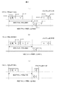
図2(a)は、上記第一の場合であるプロセッサがアイドルの場合の通常動作状態と休止状態の切り替えを時系列で示した概念図である。汎用オペレーティングシステムは、プロセッサを休止状態に置き(ステップ401)、十分に長い周期のタイマ割り込みが該プロセッサに伝達されると休止状態が解除され通常動作状態に戻り(ステップ402)、汎用オペレーティングシステムはタイマ割り込み処理を行い(ステップ403)、タイマ割り込み処理を完了すると再びプロセッサを休止状態に切り替える(ステップ404)という動作を繰り返す。 FIG. 2A is a conceptual diagram showing, in time series, switching between the normal operation state and the hibernation state when the processor is idle, which is the first case. The general-purpose operating system puts the processor in the hibernation state (step 401). When a sufficiently long timer interrupt is transmitted to the processor, the hibernation state is canceled and the normal operation state is restored (step 402). Timer interrupt processing is performed (step 403), and when the timer interrupt processing is completed, the operation of switching the processor to the sleep state again (step 404) is repeated.
図2(b)は、上記第二の場合であるプロセッサが同期化イベント待ちの場合の通常動作状態と休止状態の切り替えの動作を時系列で示した概念図である。汎用オペレーティングシステムは、プロセッサを休止状態に置き(ステップ407)、非常に短いほぼ一定周期のI/O割り込みあるいはプロセッサ間割り込みが該プロセッサに伝達されると休止状態が解除されて通常動作状態に戻り(ステップ408)、該外部割り込みで要求された処理を行い(ステップ409)、要求された処理を完了すると再びプロセッサを休止状態に切り替える(ステップ410)という動作を繰り返す。 FIG. 2B is a conceptual diagram showing, in chronological order, the operation of switching between the normal operation state and the hibernation state when the processor in the second case is waiting for a synchronization event. The general-purpose operating system puts the processor in a sleep state (step 407), and when a very short almost constant cycle I / O interrupt or inter-processor interrupt is transmitted to the processor, the sleep state is canceled and the normal operation state is restored. (Step 408) The processing requested by the external interrupt is performed (Step 409), and when the requested processing is completed, the operation of switching the processor to the sleep state again (Step 410) is repeated.
プロセッサがアイドルの場合とプロセッサが同期化イベント待ちの場合では、プロセッサ休止の周期とプロセッサ休止時間の長さに違いがある。プロセッサが同期化イベント待ちの場合のプロセッサ休止の周期412とプロセッサ休止時間411は、プロセッサがアイドルの場合のプロセッサ休止の場合と比べて共に非常に短い。共通点としては、プロセッサが同期化イベント待ちの場合とプロセッサがアイドルの場合のプロセッサ休止時間は共に定常的にほぼ一定の値をとる。 There is a difference between the processor sleep period and the length of the processor sleep time when the processor is idle and when the processor is waiting for a synchronization event. The processor halt period 412 and the processor halt time 411 when the processor is waiting for a synchronization event are both very short compared to the processor halt when the processor is idle. As a common point, the processor halt time when the processor is waiting for a synchronization event and when the processor is idle takes a constant and constant value.
仮想計算機モニタ100は、物理計算機001が有する資源を制御して、汎用オペレーティングシステムに代表されるプログラムが1つの計算機と認識するプログラム実行環境である仮想計算機を構築し、仮想計算機の上でプログラムを、物理計算機001と比較して、少しの性能低下とタイミングの違いを除けば物理計算機001上と同等に動作させる役割を担う制御プログラムである。
The
仮想計算機モニタ100は、物理計算機001が有する資源を制御して、仮想プロセッサ0(202a)と仮想プロセッサ1(202b)、仮想メモリ204、仮想I/Oデバイス205、仮想外部割り込み機構206を有する第1の仮想計算機200と、仮想プロセッサ0(302a)と仮想プロセッサ1(302b)、仮想メモリ304、仮想I/Oデバイス305、仮想外部割り込み機構306を有する第2の仮想計算機300を構築する。
The virtual machine monitor 100 controls the resources of the
第1の仮想計算機200と第2の仮想計算機300上ではそれぞれ第1の汎用オペレーティングシステム201と第2の汎用オペレーティングシステム301が動作する。第1の汎用オペレーティングシステム201と第2の汎用オペレーティングシステム301は上述の用途で後述の仮想プロセッサの仮想電源制御機能を使うことを想定する。
A first general-
第1の仮想計算機200の仮想メモリ204と仮想I/Oデバイス205、第2の仮想計算機300の仮想メモリ304と仮想I/Oデバイス305は、仮想計算機モニタ100が対応する物理計算機001の有する資源を論理分割して実現する場合もあれば、物理計算機001の資源を共有して実現する場合もあれば、物理計算機001に存在しない資源を仮想計算機モニタ100が仮想的につくり出して実現する場合もある。本実施形態においては、仮想メモリ204と304、仮想I/Oデバイス205と305は、第1の仮想計算機200と第2の仮想計算機300の上のプログラムから見て物理計算機001と同等の機能を有するとし、その詳細は問わない。
The
第1の仮想計算機200の仮想外部割り込み機構206と第2の仮想計算機300の仮想外部割り込み機構306は、それぞれ第1の仮想計算機200と第2の仮想計算機300の上のプログラムから見て、共に物理計算機001の物理外部割り込み機構006と同等の機能を有し、該物理機構と独立に動作するように仮想計算機モニタ100が仮想的に実現する。仮想外部割り込み機構は仮想プロセッサに非同期でイベント発生を通知する機能を有する。また、仮想外部割り込み機構は、仮想I/Oデバイスから仮想プロセッサへのコマンド完了通知、及びある仮想プロセッサから自身を含め指定した仮想プロセッサへの仮想プロセッサ間割り込みなどを実現するに足る機能を有する。本実施形態においては、仮想外部割り込み機構の実現方式の詳細は問わない。
The virtual external interrupt
第1の仮想計算機200の仮想プロセッサ0(202a)と仮想プロセッサ1 002b、第2の仮想計算機300の仮想プロセッサ0(302a)と仮想プロセッサ1(302b)は、それぞれ仮想電源制御機能203a、仮想電源制御機能203b、仮想電源制御機能303a、及び仮想電源制御機能303bを有する。前記仮想電源制御機能は、物理プロセッサの電源制御機能と同様に、仮想的な通常動作状態と仮想的な休止状態の2つの状態と前記2つの状態の切り替え機能を有する。
The virtual processor 0 (202a) and virtual processor 1002b of the first
本発明の仮想計算機システムにおいては、仮想計算機モニタ100は、仮想プロセッサ上のプログラムが発行する上述のプロセッサ休止命令をハードウェアに直接実行させずに、検出することで、仮想プロセッサの通常動作状態から仮想的な休止状態への切り替えを物理プロセッサの電源制御機能と独立に仮想的に実現する。
In the virtual machine system of the present invention, the
また、仮想計算機モニタ100は、前記仮想外部割り込み機構を使用することによって、仮想プロセッサの仮想的な休止状態から仮想的な通常動作状態への切り替えを、物理プロセッサの電源制御機能と独立に仮想的に実現する。 Further, the virtual machine monitor 100 uses the virtual external interrupt mechanism to switch the virtual processor from the virtual hibernation state to the virtual normal operation state independently of the power control function of the physical processor. Realize.
仮想計算機モニタ100は、第1の仮想計算機200の仮想プロセッサ0(202a)と仮想プロセッサ1(202b)及び第2の仮想計算機300の仮想プロセッサ0(302a)と仮想プロセッサ1(302b)の間で、物理計算機001の物理プロセッサ0(002a)と物理プロセッサ1(002b)を時分割共有する。それぞれの仮想プロセッサ上のプログラムは、仮想計算機モニタ100が該仮想プロセッサを、物理計算機001の物理プロセッサ0(002a)と物理プロセッサ1(002b)のいずれかに割り当てることで実行される。
The
仮想計算機モニタ100は、物理プロセッサ0(002a)と物理プロセッサ1(002b)にそれぞれアイドルプロセス020aとアイドルプロセス020bを対応付ける。仮想計算機モニタ100は、物理プロセッサに割り当てる仮想プロセッサが見つからなかったときに、該物理プロセッサに割り当てる仮想プロセッサが見つかるまで、該物理プロセッサ上で対応するアイドルプロセスを実行させる。 The virtual machine monitor 100 associates the idle process 020a and the idle process 020b with the physical processor 0 (002a) and the physical processor 1 (002b), respectively. When the virtual processor assigned to the physical processor is not found, the virtual machine monitor 100 causes the corresponding idle process to be executed on the physical processor until the virtual processor assigned to the physical processor is found.
仮想計算機モニタ100は、物理プロセッサに仮想プロセッサを割り当てるときに、該仮想プロセッサにタイムスライスと呼ぶ短いプロセッサ時間を与える。仮想プロセッサ上で動作する汎用オペレーティングシステムは、与えられたタイムスライスを使い切る前に、該仮想プロセッサの休止状態への切り替え要求を発行して、該仮想プロセッサを休止させることがある。この要因には、上述のプロセッサがアイドルの場合とワークロード実行中の同期化イベント待ちの場合がある。
When assigning a virtual processor to a physical processor, the
ワークロード実行中の同期化イベント待ちで仮想プロセッサを休止させる場合は、仮想プロセッサ休止の周期と仮想プロセッサ休止時間が共に仮想プロセッサがアイドルの場合のものに比べて非常に小さく、前記ワークロードは性能上、仮想プロセッサ休止解除から該仮想プロセッサ上のプログラムの実行再開までのレイテンシーの小ささを要求する。 When a virtual processor is paused while waiting for a synchronization event during workload execution, both the virtual processor pause period and virtual processor pause time are much smaller than those when the virtual processor is idle. In addition, a low latency from the cancellation of the virtual processor hibernation to the resumption of execution of the program on the virtual processor is requested.
一方、仮想プロセッサを休止させるときに、該仮想プロセッサに物理プロセッサを直ちに譲り渡させ、該仮想プロセッサの休止が解除されるまで、前記物理プロセッサを他の仮想プロセッサに割り当てることで、物理プロセッサを効率よく使用することができる。また、前記譲り渡し処理でアイドルの物理プロセッサが残り、アイドルプロセスを実行することがあるが、この場合はアイドルプロセスが物理プロセッサを休止状態におくことで消費電力を削減できる。複数の計算機を1台の物理計算機に集約するサーバ統合の用途で仮想計算機システムを使用する場合は、この物理プロセッサの省電力を含めた利用効率が特に重要である。 On the other hand, when a virtual processor is suspended, the physical processor is immediately transferred to the virtual processor, and the physical processor is allocated to another virtual processor until the suspension of the virtual processor is released. Can be used well. In addition, an idle physical processor may remain in the transfer process and an idle process may be executed. In this case, power consumption can be reduced by putting the physical processor in a dormant state. When a virtual computer system is used for server integration in which a plurality of computers are integrated into a single physical computer, utilization efficiency including power saving of the physical processor is particularly important.
このように仮想計算機システムにおいては、仮想プロセッサの休止に関して仮想プロセッサ単体の性能と、物理プロセッサの省電力を含めた利用効率が共に重要である。 As described above, in the virtual computer system, the performance of the virtual processor alone and the utilization efficiency including the power saving of the physical processor are important for the suspension of the virtual processor.
本発明の仮想プロセッサスケジューリング方式は、物理プロセッサの利用効率を保証できる限りにおいて、仮想プロセッサがワークロード実行中のイベント待ちで該仮想プロセッサを休止させるときに、該仮想プロセッサの休止解除から該仮想プロセッサ上のプログラムの実行再開までのレイテンシーを小さくすることを目的とする。本発明の仮想プロセッサスケジューリング方式は、仮想プロセッサ休止解除待ちの方法として、プロセッサ利用効率を保証するブロック待ち方法と仮想プロセッサ休止解除のレイテンシーを小さくするビジー待ち方法の2つの方法を有し、仮想プロセッサ休止時間の情報に基づいて、仮想プロセッサを休止させるたびに前記2つの方法から1つを動的に選択して実行するものである。 According to the virtual processor scheduling method of the present invention, when the virtual processor pauses the virtual processor while waiting for an event during the execution of the workload, the virtual processor is released from the suspension of the virtual processor as long as the utilization efficiency of the physical processor can be guaranteed. The purpose is to reduce the latency until the above program resumes execution. The virtual processor scheduling method of the present invention has two methods as a virtual processor hibernation release wait method: a block wait method for guaranteeing processor utilization efficiency and a busy wait method for reducing the latency of virtual processor hibernation release. One of the two methods is dynamically selected and executed each time the virtual processor is paused based on the pause time information.
図3は、本実施形態における、仮想計算機モニタ100の概要を示すブロック図である。仮想計算機モニタ100が有するブロックは、仮想計算機システム、物理プロセッサ、仮想計算機、及び仮想プロセッサの区分に分類される。 FIG. 3 is a block diagram showing an outline of the virtual machine monitor 100 in the present embodiment. The blocks included in the virtual machine monitor 100 are classified into a virtual machine system, a physical processor, a virtual machine, and a virtual processor.
仮想計算機モニタ001は、仮想計算機システムに対して、ブロック待ち処理時間コストTB(101)、ビジー待ち実行時間しきい値TH(102)を有する。
The
仮想計算機モニタ100は、物理プロセッサに対して、物理プロセッサごとの、物理プロセッサ構造体0(110)と物理構造体1(120)を有する。物理プロセッサ0(002a)の物理プロセッサ構造体0(110)は、物理プロセッサ状態PS(111)、後述の仮想プロセッサ休止解除時刻予測値を物理プロセッサごとに管理する仮想プロセッサ休止解除時刻管理キュー112、当該物理プロセッサ上で走行する仮想プロセッサへのポインタ、ラン状態仮想プロセッサポインタ113、当該物理プロセッサに対応付けられたアイドルプロセスへのポインタ114001を有する。物理プロセッサ1(002b)の物理プロセッサ構造体1(120)も同様である。
The
仮想計算機モニタ100は、仮想計算機に対して、仮想計算機ごとに、仮想プロセッサレディキュー130と140、仮想プロセッサブロックキュー131と141を有する。
The
仮想計算機モニタ100は、仮想プロセッサごとに、仮想プロセッサ構造体150a、150b、150c、150dを有する。仮想プロセッサ構造体150aは、仮想プロセッサ状態VS(151a)、スケジュール状態SS(152a)、仮想プロセッサコンテキスト領域153a、仮想プロセッサ休止解除通知フラグNF(154a)、仮想プロセッサ休止時間の予測値E(155a)、仮想プロセッサ休止解除時刻予測値F(156a)、仮想プロセッサ休止開始時刻TS(157a)、仮想プロセッサ休止時間X(158a)、最近N回の仮想プロセッサ休止時間を格納する配列、仮想プロセッサ休止時間履歴テーブルR[i]、i=0、1、・・・、N−1 159a、前記仮想プロセッサ休止時間履歴テーブルの中で最も古い仮想プロセッサ休止時間が格納されたエントリのインデックス、最古仮想プロセッサ休止インデックスK(160a)、最近N回の仮想プロセッサ休止時間の総和S(161a)を有する。仮想プロセッサ構造体150b、150c、及び150dも同様である。
The
以上の図1と図3記載の情報を用いて、本実施形態における仮想プロセッサスケジューリング方式を説明する。 The virtual processor scheduling method in the present embodiment will be described using the information described above with reference to FIGS.
最初に、仮想プロセッサのコンテキスト切り替え方式を説明する。第1の仮想計算機200の仮想プロセッサ0(202a)と第2の仮想計算機300の仮想プロセッサ0(302a)、及び物理プロセッサ0(002a)を例とする。仮想プロセッサのコンテキスト切り替えは、仮想プロセッサ間の連続した切り替えとは限らず、仮想プロセッサからアイドルプロセスに切り替え、アイドルプロセスから仮想プロセッサに切り替え、間にアイドルプロセスを挟む場合があるが、仮想プロセッサに関して言えば処理に違いがないため、この場合の説明は省略する。
First, the virtual processor context switching method will be described. The virtual processor 0 (202a) of the first
仮想プロセッサコンテキストは、仮想プロセッサのプロセッサレジスタ値と仮想プロセッサ制御情報のスナップショットである。第1の仮想計算機200の仮想プロセッサ0(202a)の仮想プロセッサ構造体150aの仮想プロセッサコンテキスト領域153aは、該仮想プロセッサの仮想プロセッサコンテキストを保持する。仮想計算機システムには複数のアクティブな仮想プロセッサが存在するが、1つの物理プロセッサのハードウェアレジスタは一面である。仮想計算機モニタ100は、仮想プロセッサ0(202a)が物理プロセッサ0(002a)上で走行中の場合は、仮想プロセッサ0(202a)の仮想プロセッサコンテキストを物理プロセッサ0(002a)のハードウェアレジスタに保持する。仮想プロセッサ0(202a)が走行中でない場合は、仮想プロセッサコンテキスト領域153aに仮想プロセッサ0(202a)のコンテキストを保持する。
The virtual processor context is a snapshot of the processor register value of the virtual processor and the virtual processor control information. The virtual processor context area 153a of the
仮想計算機モニタ100は、物理プロセッサ0(002a)に割り当てる仮想プロセッサを第1の仮想計算機200の仮想プロセッサ0(202a)から第2の仮想計算機300の仮想プロセッサ0(302a)に切り替えるときは、まず第1の仮想計算機200の仮想プロセッサ0(202a)の仮想プロセッサコンテキストを仮想プロセッサコンテキスト領域153aに保存し、それから第2の仮想計算機300の仮想プロセッサ0(302a)の仮想プロセッサコンテキストを仮想プロセッサコンテキスト領域153bから物理プロセッサ0(002a)にロードする。その後、物理プロセッサ0(002a)はロードされた仮想プロセッサコンテキストから第2の仮想計算機300の仮想プロセッサ0(302a)の実行を開始する。
When the virtual machine monitor 100 switches the virtual processor assigned to the physical processor 0 (002a) from the virtual processor 0 (202a) of the first
以上のハードウェアレベルでの仮想計算機モニタ100による仮想プロセッサの切り替えをコンテキスト切り替えと呼ぶ。仮想プロセッサコンテキストは、プロセッサ全体を表すので数も種類も多く、さらには物理プロセッサがプロセッサ仮想化アシスト機能を有する場合には、該機能の制御データの退避回復も必要であるため、コンテキスト切り替えは処理時間の大きな処理である。 The switching of virtual processors by the virtual machine monitor 100 at the above hardware level is called context switching. Since the virtual processor context represents the entire processor, there are many types and types. Furthermore, if the physical processor has a processor virtualization assist function, it is necessary to save and restore the control data of the function. It is a time consuming process.
仮想プロセッサのスケジューリングを行うのに用いる、仮想プロセッサごとに有する状態情報、仮想プロセッサ状態VS、仮想プロセッサ休止解除通知フラグNF、スケジュール状態SSを説明する。第1の仮想計算機001の仮想プロセッサ0 001を例とする。
The state information, virtual processor state VS, virtual processor hibernation release notification flag NF, and schedule state SS that are used for virtual processor scheduling will be described. The
仮想プロセッサ状態VS(151a)は、仮想通常動作状態VEXEと仮想休止状態VHLTの2値をとる。仮想計算機モニタ100は、仮想プロセッサ0(202a)が、仮想通常動作状態VEXEにあるときは、該仮想プロセッサ上のプログラムを実行可とし、仮想プロセッサ0(202a)が仮想休止状態VHLTにあるときは、該仮想プロセッサ上のプログラムを実行不可とする。仮想プロセッサ状態VS(152a)の仮想通常動作状態VEXEから仮想休止状態VHLTへの変更と、仮想休止状態VHLTから仮想通常動作状態VEXEへの変更は共に、仮想プロセッサ0(202a)が物理プロセッサに割り当てられたときに該物理プロセッサ上でのみ行う。 The virtual processor state VS (151a) takes two values, a virtual normal operation state VEXE and a virtual sleep state VHLT. When the virtual processor 0 (202a) is in the virtual normal operation state VEXE, the virtual machine monitor 100 can execute the program on the virtual processor, and when the virtual processor 0 (202a) is in the virtual hibernation state VHLT. The program on the virtual processor cannot be executed. The virtual processor 0 (202a) is assigned to the physical processor in both the change from the virtual normal operation state VEXE to the virtual hibernation state VHLT and the change from the virtual sleep state VHLT to the virtual normal operation state VEXE in the virtual processor state VS (152a). Only on that physical processor.
仮想プロセッサ休止解除通知フラグNF(154a)は、仮想プロセッサ状態VS(151a)の制御を同期化するためのものである。仮想プロセッサ休止解除通知フラグNF(154a)は、真と偽の2値をとる。仮想プロセッサ休止解除通知フラグNF(154a)の偽から真への変更は仮想プロセッサ0(202a)の物理プロセッサ上での動作とは独立に非同期に任意の時点で行い、仮想プロセッサ休止解除通知フラグNF(154a)の真から偽への変更は、仮想プロセッサ0(202a)が物理プロセッサに割り当てられたときに、該物理プロセッサ上でのみ行う。 The virtual processor halt release notification flag NF (154a) is for synchronizing the control of the virtual processor state VS (151a). The virtual processor halt release notification flag NF (154a) takes two values, true and false. The virtual processor hibernation release notification flag NF (154a) is changed from false to true at any time asynchronously with the operation of the virtual processor 0 (202a) on the physical processor. The change of (154a) from true to false is performed only on the physical processor when the virtual processor 0 (202a) is assigned to the physical processor.
スケジュール状態SS(152a)は、ラン状態RUN、レディ状態RDY、及びブロック状態BLKの3値をとる。ラン状態RUNは、仮想プロセッサ0(202a)が物理プロセッサに割り当てられて、該物理プロセッサを使用している状態である。レディ状態RDYは、仮想プロセッサ0(202a)が物理プロセッサに割り当て可能だが、別の仮想プロセッサが物理プロセッサ上で走行中の為物理プロセッサが空いていないので停止している状態である。ブロック状態BLKは、特定のイベントが発生するまではたとえ物理プロセッサが空いていても仮想プロセッサ0(202a)が走行不可の状態である。 The schedule state SS (152a) takes three values: a run state RUN, a ready state RDY, and a block state BLK. The run state RUN is a state in which the virtual processor 0 (202a) is allocated to the physical processor and is using the physical processor. The ready state RDY is a state in which the virtual processor 0 (202a) can be assigned to the physical processor, but is stopped because another virtual processor is running on the physical processor and the physical processor is not free. The block state BLK is a state in which the virtual processor 0 (202a) cannot run until a specific event occurs even if the physical processor is free.
仮想計算機モニタ100は、仮想プロセッサ0(202a)のスケジュール状態SS(152a)が物理プロセッサ0(002a)上でラン状態RUNにあるときは、該仮想プロセッサを、物理プロセッサ0(002a)の物理プロセッサ構造体0(110)のラン状態仮想プロセッサポインタ113で管理し、仮想プロセッサ0(202a)のスケジュール状態SS(152a)がレディ状態RDY及びブロック状態BLKにあるときは、それぞれ該仮想プロセッサが属する第1の仮想計算機200の仮想プロセッサレディキュー130と仮想プロセッサブロックキュー140で管理する。
When the schedule state SS (152a) of the virtual processor 0 (202a) is in the run state RUN on the physical processor 0 (002a), the
仮想計算機モニタ100は、物理プロセッサ0(002a)に仮想プロセッサを割り当てるときは、所定のアルゴリズムに従い、いずれかの仮想計算機の仮想プロセッサレディキューから1つ仮想プロセッサを取り出して、物理プロセッサ0(002a)に割り当てる。その際、前記仮想プロセッサを物理プロセッサ0(002a)の物理プロセッサ構造体110のラン状態仮想プロセッサポインタ113にポイントさせる。
When assigning a virtual processor to the physical processor 0 (002a), the
仮想プロセッサの仮想プロセッサ状態SS、スケジュール状態VS、及び仮想プロセッサ休止解除通知フラグNFを連動させた、仮想プロセッサの状態遷移を説明する。図4に仮想プロセッサの状態遷移図を示す。 The state transition of the virtual processor in which the virtual processor state SS, the schedule state VS, and the virtual processor suspension release notification flag NF of the virtual processor are linked will be described. FIG. 4 shows a state transition diagram of the virtual processor.
仮想計算機モニタは仮想プロセッサを物理プロセッサに割り当て、該仮想プロセッサ上のプログラムを実行させるときは、該仮想プロセッサの仮想プロセッサ状態SSをラン状態RUNとし、スケジュール状態VSを仮想通常動作状態VEXEとする。仮想プロセッサ休止解除通知フラグNFの値は問わない(状態1 501)。
When the virtual machine monitor assigns a virtual processor to a physical processor and executes a program on the virtual processor, the virtual processor state SS of the virtual processor is set to the run state RUN, and the schedule state VS is set to the virtual normal operation state VEXE. The value of the virtual processor hibernation release notification flag NF does not matter (
ステップ1 511は、前記状態1 501の仮想プロセッサがタイムスライスを使い切ったかあるいは他に優先度の高い仮想プロセッサが現れた場合に、仮想プロセッサの仮想プロセッサ状態VSをVEXEにしたままスケジュール状態SSをレディ状態RDYに変更し、該仮想プロセッサを属する仮想計算機の仮想プロセッサレディキューに挿入する(状態2 502)処理を示す。
ステップ2 512は、前記状態2 502の仮想プロセッサを物理プロセッサへの割り当て対象に選択したときに、属する仮想計算機の仮想プロセッサレディキューから取り出し、割り当て先の物理プロセッサのラン状態仮想プロセッサポインタに登録して、スケジュール状態SSをラン状態RUNに変更して前記状態1 501に戻る処理を示す。
ステップ3 513は、前記状態1 501の仮想プロセッサが仮想休止状態への切り替え要求を受けると、まずスケジュール状態は変更せずに、仮想プロセッサ状態VSを仮想休止状態VHLTに変更する(状態3 503)処理を示す。
In
ステップ4 514は、後述のビジー待ち方法によって仮想休止状態の解除を待つ場合に、状態3 503のまま仮想プロセッサ休止解除通知フラグNFが真にされるのを繰り返し調べる処理を示す。
ステップ5 515は、前記のステップ4 514を途中で中断するかあるいは初めから後述のブロック待ち方法によって前記仮想休止状態の解除を待つ場合に、スケジュール状態SSをブロック状態BLKに変更して、該仮想プロセッサを属する仮想計算機の仮想プロセッサブロックキューに挿入する(状態4 504)処理を示す。
ステップ6 516は、前記状態3 503の仮想プロセッサに対して仮想休止状態の解除を行うときに、仮想プロセッサの仮想プロセッサ休止解除通知フラグNFを真に設定する(状態5 505)処理を示す。
ステップ6 516は、前記状態4 001の仮想プロセッサに対して仮想休止状態の解除を行うときに、仮想プロセッサの仮想プロセッサ休止解除通知フラグNFを真に設定し、属する仮想計算機の仮想プロセッサブロックキューから取り出し、スケジュール状態SSをレディ状態RDYに変更して、属する仮想計算機の仮想プロセッサレディキューに挿入する(状態6 506)処理を示す。
ステップ7 517は、前記状態6 506の仮想プロセッサを物理プロセッサへの割り当て対象に選択すると、該仮想プロセッサを属する仮想計算機の仮想プロセッサレディキューから取り出し、割り当て先の物理プロセッサのラン状態仮想プロセッサポインタに登録して、状態5 505に遷移する処理を示す。
In
ステップ8 518は、前記状態5 505にある仮想プロセッサは、仮想プロセッサ休止解除通知フラグNFが真にされていることを検出して、前記フラグを偽に変更し、仮想プロセッサ状態VSをVEXEに変更して、前記状態1 001に戻す処理を示す。
In
ステップ1 511からステップ9 519までの処理のうち、ステップ1 511、ステップ3 513、ステップ4 514、ステップ5 515、ステップ8 518、及びステップ9 519は、仮想プロセッサが物理プロセッサに割り当てられたときに該物理プロセッサ上で、前記仮想プロセッサと同期して行う。ステップ2 512、ステップ6 516、及びステップ7 517は、仮想プロセッサの物理プロセッサ上の動作とは独立に非同期に任意の時点で行う。
Of the processes from
以上の説明を基に、仮想プロセッサのスケジューリングと同期化を含んだ仮想プロセッサの仮想休止状態と仮想通常動作状態の間の切り替え方式を説明する。仮想プロセッサの仮想休止状態と仮想通常動作状態の間の切り替えは、仮想プロセッサ休止解除待ち処理と仮想プロセッサ休止解除通知処理の2つの処理から成る。 Based on the above description, a switching method between the virtual sleep state and the virtual normal operation state of the virtual processor including the scheduling and synchronization of the virtual processor will be described. Switching between the virtual hibernation state and the virtual normal operation state of the virtual processor consists of two processes: a virtual processor hibernation release wait process and a virtual processor hibernation release notification process.
図5に時系列で示した、第1の仮想計算機200の仮想プロセッサ0(202a)の仮想休止状態と仮想通常動作状態の間の切り替えを例に取り上げ、仮想プロセッサ休止解除待ち処理と仮想プロセッサ休止解除通知処理を説明する。
Taking as an example the switching between the virtual hibernation state and the virtual normal operation state of the virtual processor 0 (202a) of the first
まず、図5の内容を簡単に説明する。第1の仮想計算機200の仮想プロセッサ0(202a)と仮想プロセッサ1(202b)がそれぞれ物理プロセッサ0(002a)と物理プロセッサ1(002b)上で走行中である。第2の仮想計算機300の仮想プロセッサ0 302と仮想プロセッサ1(302b)は共に仮想休止状態にあり、物理プロセッサに割り当てられていないものとする。説明を単純にするために図5では省略する。
First, the contents of FIG. 5 will be briefly described. The virtual processor 0 (202a) and the virtual processor 1 (202b) of the first
仮想プロセッサ0(202a)上のプログラムが休止状態への切り替え要求を発行すると、仮想計算機モニタ100は該要求をハードウェアに直接実行させずに検出し、仮想プロセッサ状態を仮想休止状態に変更し、仮想プロセッサ0(202a)上のプログラムの実行を停止させる。仮想プロセッサ1(202b)上のプログラムが仮想プロセッサ0(202b)に仮想プロセッサ間割り込みを発行すると、仮想計算機モニタ100は、該割り込みを検出して、該割り込みの動作を仮想的に実現すると共に、仮想プロセッサ0(202a)の仮想プロセッサ状態を仮想通常動作状態に切り替え、仮想プロセッサ0(202a)上のプログラムの実行を再開する。
When a program on the virtual processor 0 (202a) issues a request to switch to the hibernation state, the
図6に仮想プロセッサ休止除待ち処理のフローチャートを示す。図5の例に沿って、図6のフローチャートに従い、仮想プロセッサ休止解除待ち処理を説明する。 FIG. 6 shows a flowchart of the virtual processor suspension removal waiting process. In accordance with the example of FIG. 5, the virtual processor hibernation release waiting process will be described according to the flowchart of FIG.
仮想プロセッサ0(202a)と仮想プロセッサ1(202b)が共に状態1 501にあるとする。仮想プロセッサ0(202a)上のプログラムが休止状態への切り替え要求を発行すると、仮想計算機モニタ100は、該要求をハードウェアに直接実行させずに検出して、仮想プロセッサ状態VS(151a)を仮想休止状態VHLTに変更する(ステップA 600)。
Assume that both virtual processor 0 (202a) and virtual processor 1 (202b) are in
仮想計算機モニタ100は、後述する仮想プロセッサ休止解除待ち方法選択処理にて仮想プロセッサ0の仮想プロセッサ休止解除待ち処理としてブロック待ち方法を選択したならば(ステップB 602)、スケジュール状態SS(152a)をBLKに変更して、仮想プロセッサ0(202a)を第1の仮想計算機200の仮想プロセッサブロックキュー131に挿入して(ステップC 602)、コンテキスト切り替えを実行して(ステップD 603)物理プロセッサ0(002a)を譲り渡す。
If the
仮想計算機モニタ100は、物理プロセッサ0(002a)に割り当てる仮想プロセッサが見つからないので、物理プロセッサ0(002a)の物理プロセッサ構造体0(110)のアイドルプロセスポインタ114がポイントするアイドルプロセスを実行する。
Since the virtual processor assigned to the physical processor 0 (002a) is not found, the
一方、仮想計算機モニタ100は、後述する仮想プロセッサ休止解除待ち方法選択処理にてビジー待ち方法を選択したならば(ステップB 601)、仮想プロセッサ休止解除通知フラグNF(154a)が真になるのを繰り返し調べる(ステップE 604)。仮想プロセッサ休止解除通知フラグNF(154a)が真に設定されるのを確認する前に後述のビジー待ち方法継続チェック処理にてビジー待ち方法を途中で中断した場合は(ステップF 605)、初めからブロック待ち方法を選択したのと同様に、ステップB 602とステップD 603を実行して物理プロセッサ0(002a)を譲り渡す。
On the other hand, if the
ビジー待ち方法を選択しステップE 604にて後述の仮想プロセッサ休止解除通知処理によって、仮想プロセッサ休止解除通知フラグNF(154a)が真にされたのを確認すると、仮想プロセッサ休止解除通知フラグNF(154a)を偽にして(ステップH 607)、仮想プロセッサ状態VS(151a)を仮想実行状態VEXEに変更して(ステップI 608)、仮想プロセッサ0(202a)上のプログラムの実行を再開する。 When the busy waiting method is selected and it is confirmed in Step E604 that the virtual processor halt release notification flag NF (154a) is set to true by the virtual processor halt release notification processing described later, the virtual processor halt release notification flag NF (154a) ) Is set to false (step H607), the virtual processor state VS (151a) is changed to the virtual execution state VEXE (step I608), and the execution of the program on the virtual processor 0 (202a) is resumed.
ブロック待ち方法を選択したときは、後述の仮想プロセッサ休止解除通知処理によって起こされ、さらに物理プロセッサ0(002a)への割り当て対象として選択され、コンテキスト切り替えにされて物理プロセッサ0(002a)上で実行を再開すると(ステップG 606)、仮想プロセッサ休止解除通知フラグNF(154a)を偽にして(ステップH 607)、仮想プロセッサ状態VS(151a)を仮想実行状態VEXEに変更して(ステップI 608)、仮想プロセッサ0(202a)上のプログラムの実行を再開する。 When the block waiting method is selected, it is caused by a virtual processor hibernation release notification process, which will be described later, and is further selected as a target to be assigned to the physical processor 0 (002a), switched to the context, and executed on the physical processor 0 (002a). Is resumed (step G606), the virtual processor halt release notification flag NF (154a) is set to false (step H607), and the virtual processor state VS (151a) is changed to the virtual execution state VEXE (step I608). The program execution on the virtual processor 0 (202a) is resumed.
図7に仮想プロセッサ休止解除通知処理のフローチャートを示す。続けて仮想プロセッサ休止解除通知処理を説明する。 FIG. 7 shows a flowchart of the virtual processor halt release notification process. Next, the virtual processor halt release notification process will be described.
仮想プロセッサ1(202b)が仮想プロセッサ0(202a)に仮想プロセッサ間割り込みを発行すると、仮想計算機モニタ100が該割り込み発行を検出し、該割り込みの動作を仮想的に実現する。それから仮想プロセッサ休止解除通知処理を開始する。仮想プロセッサの状態によらずに仮想プロセッサ休止解除通知フラグNF(154a)を真にする(ステップJ 609)。仮想プロセッサ0(202a)のスケジュール状態SS(152a)がBLKであるならば(ステップK 610)、仮想プロセッサ0(202a)を第1の仮想計算機200の仮想プロセッサブロックキュー131から取り出して、スケジュール状態SS(152a)をレディ状態RDYに変更して第1の仮想計算機200の仮想プロセッサレディキュー130に挿入する(ステップK 611)。
When the virtual processor 1 (202b) issues an inter-virtual processor interrupt to the virtual processor 0 (202a), the
仮想プロセッサ0(202a)のスケジュール状態SS(152a)がBLK以外、すなわちラン状態RUNあるいはレディ状態RDYの場合は以降何もしない。仮想計算機モニタ100は物理プロセッサ0(002a)への割り当て対象として仮想プロセッサ0(202a)を選択すると、スケジュール状態SS(152a)をラン状態RUNに変更して、仮想プロセッサ0(202a)の仮想プロセッサコンテキストを物理プロセッサ0(002a)に回復して、仮想プロセッサ0(202a)を起動する(ステップG 606)。
If the schedule state SS (152a) of the virtual processor 0 (202a) is other than BLK, that is, the run state RUN or the ready state RDY, nothing is performed thereafter. When the
図5の例を基にブロック待ち方法とビジー待ち方法の性能と処理コストを考察する。性能は、仮想プロセッサ休止解除レイテンシーの大きさで見る。処理コストは、仮想プロセッサが休止解除待ちを開始してから該仮想プロセッサ上のプログラムの実行が再開されるまでの間に、物理プロセッサを該仮想プロセッサの休止を制御すること以外に使えるプロセッサ時間の割合、空きプロセッサ利用率で見る。 Based on the example of FIG. 5, the performance and processing cost of the block waiting method and the busy waiting method will be considered. Performance is measured by the size of the virtual processor hibernation release latency. The processing cost is the amount of processor time that can be used for the physical processor other than controlling the pause of the virtual processor after the virtual processor starts waiting for the hibernation release until the program execution on the virtual processor is resumed. View by percentage and free processor utilization.
図6と図7のステップA 600からステップL 611までのそれぞれの処理時間コストの大小関係は次のとおりである。
The magnitude relationship between the processing time costs from
ステップAコスト、ステップBコスト、ステップFコスト、ステップGコスト、ステップHコスト、ステップIコスト << ステップCコスト、ステップDコスト、ステップEコスト、ステップJコスト、ステップKコスト
ステップD 603とステップK 610はコンテキスト切り替え処理のため処理時間が非常に大きい。ステップC 602とステップJ 609はキュー操作処理であり、コンテキスト切り替え処理に比べれば小さいが処理時間は大きい。ステップE 604はビジー待ち処理のため処理時間は最大になりえるが、このステップE 604がコストとなるかどうかは、その間他に行う処理があるかどうかによって決まる。残りのステップA 600、ステップB 601、ステップF 605、ステップG 606、ステップH 607、及びステップI 608はビット参照・操作処理のため、処理時間は全体からすれば非常に小さい。
Step A cost, Step B cost, Step F cost, Step G cost, Step H cost, Step I cost << Step C cost, Step D cost, Step E cost, Step J cost, Step K
図8(a)はブロック待ち方法を選択した場合、図8(b)はビジー待ち方法を選択したが途中でブロック待ちに変更した場合、図8(c)はビジー待ち方法を選択した場合の、仮想プロセッサ休止解除待ち処理と仮想プロセッサ休止解除通知処理を時系列で示したものである。それぞれの場合の仮想プロセッサ休止解除レイテンシーと物理プロセッサ0の空きプロセッサ利用率を示す。以下では図と同様に例えばステップAコストをAと略記することで記述を簡略化する。
8A shows the case where the block waiting method is selected, FIG. 8B shows the case where the busy waiting method is selected, but the block waiting is changed in the middle, and FIG. 8C shows the case where the busy waiting method is selected. The virtual processor hibernation release waiting process and the virtual processor hibernation release notification process are shown in time series. The virtual processor halt release latency and the free processor utilization rate of the
図8(a)に示すブロック待ち方法を選択した場合の仮想プロセッサ休止解除レイテンシーと空きプロセッサ利用率はそれぞれ次のとおりである。
ブロック待ちの仮想プロセッサ休止解除レイテンシー=(H+I+J)+(K+G)
ブロック待ちの物理プロセッサ0の空きプロセッサ利用率=(VP休止時間−(A+B+C+D)+(H+I+J))/(VP休止時間+(H+I+J)+(K+G))
The virtual processor halt release latency and the free processor utilization when the block wait method shown in FIG. 8A is selected are as follows.
Virtual processor hibernation release latency waiting for block = (H + I + J) + (K + G)
Free processor utilization of
図8(b)に示すビジー待ち方法を選択したが途中でブロック待ち方法に変更した場合の仮想プロセッサ休止解除レイテンシーと空きプロセッサ利用率はそれぞれ次のとおりである。
ビジー待ち→ブロック待ちの仮想プロセッサ休止解除レイテンシー=(H+I+J)+(K+G)
ビジー待ち→ブロック待ちの物理プロセッサ0の空きプロセッサ利用率=(VP休止時間−(A+B+E+F+C+D)+(H+I+J))/(VP休止時間+(H+I+J)+(K+G))
When the busy waiting method shown in FIG. 8B is selected but changed to the block waiting method in the middle, the virtual processor hibernation release latency and the free processor utilization rate are as follows.
Busy waiting-> block waiting virtual processor suspension release latency = (H + I + J) + (K + G)
Busy waiting → Free processor utilization rate of
図8(c)に示すビジー待ち方法を選択した場合の仮想プロセッサ休止解除レイテンシーと空きプロセッサ利用率はそれぞれ次のとおりである。
ビジー待ちの仮想プロセッサ休止解除レイテンシー=H+(K+G)
ビジー待ちの物理プロセッサ0の空きプロセッサ利用率=0
The virtual processor halt release latency and the free processor utilization when the busy waiting method shown in FIG. 8C is selected are as follows.
Busy waiting virtual processor hibernation release latency = H + (K + G)
Free processor utilization rate of busy
仮想プロセッサ休止解除レイテンシーを比較すると、以下のとおりである。
ビジー待ち<<ブロック待ち=(ビジー待ち→ブロック待ち)
A comparison of the virtual processor hibernation release latency is as follows.
Busy waiting << Block waiting = (Busy waiting → Block waiting)
同様に空きプロセッサ利用率を比較すると、以下のとおりである。
0=ビジー待ち<<(ビジー待ち→ブロック待ち)<ブロック待ち
Similarly, the available processor utilization rates are compared as follows.
0 = busy wait << (busy wait → block wait) <block wait
ブロック待ち方法は、空きプロセッサ利用率が最も高い、つまり物理プロセッサ利用効率の高い方法である。ビジー待ち方法は、仮想プロセッサ休止解除レイテンシーが最も小さく性能面で優れている。ビジー待ち方法は空きプロセッサ利用率が0であり、物理プロセッサを他の用途には使うことはできないが、後述のように、ビジー待ち実行中は物理プロセッサを休止させることで消費電力を減らすことができるので、他に動作させる仮想プロセッサが存在しない場合は問題とならない。ビジー待ち方法を途中でやめてブロック待ち方法に切り替えた場合は、最初からブロック待ち方法を選択した場合に比べて空きプロセッサ利用率は低いが、仮想プロセッサ休止解除レイテンシーは最初からブロック待ち方法を選択した場合と同じである。ビジー待ち方法から途中でブロック待ち方法に切り替えることは避けなければならない。 The block waiting method has the highest free processor utilization rate, that is, a physical processor utilization efficiency is high. The busy waiting method has the smallest virtual processor hibernation release latency and is excellent in performance. In the busy wait method, the utilization rate of the free processor is 0, and the physical processor cannot be used for other purposes. However, as described later, the power consumption can be reduced by pausing the physical processor during busy wait execution. This is possible, so there is no problem if there are no other virtual processors to operate. When the busy wait method is stopped halfway and switched to the block wait method, the free processor utilization is lower than when the block wait method is selected from the beginning, but the virtual processor hibernation release latency selects the block wait method from the beginning. Same as the case. Switching from the busy wait method to the block wait method on the way should be avoided.
以上から、前述の仮想プロセッサ休止解除待ち方法選択処理の方針を、プロセッサ利用効率が要求される場合はブロック待ち方法を選択し、他に動作させる仮想プロセッサが存在せずかつ仮想プロセッサ休止解除レイテンシーの小ささが要求される場合にビジー待ち方法を選択し、ビジー待ち方法から途中でブロック待ち方法に切り替えることを避けることと定める。 From the above, the policy of the virtual processor hibernation release waiting method selection processing described above is selected. When processor utilization efficiency is required, the block wait method is selected, and there is no other virtual processor to be operated and the virtual processor hibernation release latency is When a small size is required, the busy waiting method is selected, and it is determined that switching from the busy waiting method to the block waiting method is avoided.
次に、この方針を実現するために使用する、仮想プロセッサ休止時間、仮想プロセッサ休止時間予測値、及び仮想プロセッサ休止解除時刻予測値の算出方法と管理方法を説明する。第1の仮想計算機200の仮想プロセッサ0(202a)を例とする。
Next, a calculation method and a management method of the virtual processor halt time, the virtual processor halt time predicted value, and the virtual processor halt release time predicted value used to realize this policy will be described. The virtual processor 0 (202a) of the first
仮想プロセッサ0(202a)の仮想プロセッサ休止時間を、仮想プロセッサ0(202a)の仮想プロセッサ休止解除通知フラグNF(154a)が真に設定されるのを待ち始めてから、該仮想プロセッサ休止解除通知フラグNFが真に設定されるまでの時間と定義する。直近のN回の仮想プロセッサ休止時間の平均値を仮想プロセッサ休止時間予測値Eとする。 The virtual processor 0 (202a) virtual processor suspend time starts to wait until the virtual processor 0 (202a) virtual processor suspend release notification flag NF (154a) is set to true, and then the virtual processor suspend release notification flag NF Is defined as the time until is set to true. The average value of the latest N virtual processor pause times is defined as a virtual processor pause time prediction value E.
仮想プロセッサ0の仮想プロセッサ休止時間Xの算出方法を、図9(a)のフローチャートに基づき説明する。
A method for calculating the virtual processor halt time X of the
上述の仮想プロセッサ休止解除待ち処理において、仮想プロセッサ0(202a)の仮想プロセッサ状態VS(151a)を仮想休止状態VHLTに変更した後で仮想プロセッサ0(202a)の仮想プロセッサ休止解除通知フラグNF(154a)が真に設定されるのを待ち始める直前に、その時点のシステム時刻を仮想プロセッサ0(202a)の仮想プロセッサ休止開始時刻 TS(157a)に保持する(ステップ620)。 In the virtual processor hibernation release waiting process described above, after changing the virtual processor state VS (151a) of the virtual processor 0 (202a) to the virtual hibernation state VHLT, the virtual processor hibernation release notification flag NF (154a) of the virtual processor 0 (202a) ) Is held at the virtual processor suspension start time TS (157a) of the virtual processor 0 (202a) immediately before starting to wait until it is set to true (step 620).
上述の仮想プロセッサ休止解除通知処理において、仮想プロセッサ0(202a)の仮想プロセッサ休止解除通知フラグNF(154a)を真に設定した直後に、その時点のシステム時刻t1から、保存した仮想プロセッサ休止開始時刻TS(157a)を引くことで、仮想プロセッサ0(202a)のプロセッサ休止時間t1−TSを求め、仮想プロセッサ休止時間X(158a)に保存する(ステップ621)。 In the virtual processor halt release notification process described above, immediately after the virtual processor halt release notification flag NF (154a) of the virtual processor 0 (202a) is set to true, the stored virtual processor halt start time from the current system time t1 By subtracting TS (157a), the processor halt time t1-TS of the virtual processor 0 (202a) is obtained and stored in the virtual processor halt time X (158a) (step 621).
仮想プロセッサ0(202a)の仮想プロセッサ休止時間予測値E(155a)の算出方法を、図9(b)のフローチャートに基づき説明する。図10にはプロセッサ休止時間予測値E(155a)の算出方法の概念図を示す。 A method of calculating the predicted virtual processor halt time E (155a) of the virtual processor 0 (202a) will be described with reference to the flowchart of FIG. FIG. 10 shows a conceptual diagram of a method of calculating the processor pause time predicted value E (155a).
仮想プロセッサ休止時間予測値E(155a)の算出は、前記の仮想プロセッサ休止時間X(158a)の算出に続けて、仮想プロセッサ休止解除通知処理の中で行う。 The virtual processor halt time predicted value E (155a) is calculated in the virtual processor halt release notification process following the calculation of the virtual processor halt time X (158a).
上述の仮想プロセッサ休止解除通知処理において、算出した仮想プロセッサ休止時間X(158a)によって、直近N回の仮想プロセッサ休止時間の総和S(161a)を更新する。最古仮想プロセッサ休止インデックスK(160a)は仮想プロセッサ休止時間履歴テーブルR[i]、i=0、1、・・・、N−1 159aの中で最古の仮想プロセッサ休止時間をさしているので、直近N回の仮想プロセッサ休止時間の総和S(161a)から前記最古の仮想プロセッサ休止時間R[K]を引き、今回の仮想プロセッサ休止時間X (158a)を足すことで、直近N回の仮想プロセッサ休止時間の総和S(161a)を更新する、すなわち(式1)と求める(ステップ622)。
Snew = Sold − R[K] + X (式1)
In the virtual processor halt release notification process described above, the sum S (161a) of the latest N virtual processor halt times is updated with the calculated virtual processor halt time X (158a). Since the oldest virtual processor pause index K (160a) indicates the oldest virtual processor pause time in the virtual processor pause time history table R [i], i = 0, 1,..., N-1 159a. , Subtracting the oldest virtual processor pause time R [K] from the sum S (161a) of the latest N virtual processor pause times and adding the current virtual processor pause time X (158a) The sum S (161a) of the virtual processor halt time is updated, that is, (Equation 1) is obtained (step 622).
Snew = Sold−R [K] + X (Formula 1)
この更新した直近N回の仮想プロセッサ休止時間の総和SをNで割ることで、最近N回の仮想プロセッサ休止時間の平均値、次の仮想プロセッサ休止時間の予測値E(155a)を求める、すなわち(式2)と求める(ステップ623)。
E = S/N (式2)
By dividing the updated total N of the most recent N virtual processor pause times by N, an average value of the latest N virtual processor pause times and a predicted value E (155a) of the next virtual processor pause time are obtained. (Expression 2) is obtained (step 623).
E = S / N (Formula 2)
最後に、仮想プロセッサ休止時間履歴テーブルR[i]、i=0、1、・・・、N−1 159aを更新する。最古仮想プロセッサ休止インデックスK(160a)が指す仮想プロセッサ休止時間履歴テーブルのエントリR[K]に直近仮想プロセッサ休止時間X(157a)を保存し、すなわち(式3)とし(ステップ624)、
R[K] = X (式3)
最古仮想プロセッサ休止インデックスKに+1を足し、KがNと等しくなったならば、Kを0とする、すわわち(式4)と求める(ステップ625)。
K = (++K) mod N (式4)
Finally, the virtual processor halt time history table R [i], i = 0, 1,..., N−1 159a is updated. The latest virtual processor halt time X (157a) is stored in the entry R [K] of the virtual processor halt time history table pointed to by the oldest virtual processor halt index K (160a), that is, (Equation 3) is set (step 624).
R [K] = X (Formula 3)
When +1 is added to the oldest virtual processor halt index K and K becomes equal to N, K is set to 0, that is, (Equation 4) is obtained (step 625).
K = (++ K) mod N (Formula 4)
(式1)、(式2)、(式3)、及び(式4)を見ると分かるように、仮想プロセッサ休止時間予測値E(155a)を、直近N回の仮想プロセッサ休止時間の総和を求めなおす必要なく、仮想プロセッサ0の情報のみを用いて一定の処理時間で算出することができる。
As can be seen from (Equation 1), (Equation 2), (Equation 3), and (Equation 4), the virtual processor pause time predicted value E (155a) is calculated as the sum of the latest N virtual processor pause times. There is no need to obtain it again, and it can be calculated in a fixed processing time using only the information of the
仮想プロセッサ0(202a)の仮想プロセッサ休止解除時刻予測値F(156a)の算出方法と管理方法を、図9(c)のフローチャートに基づき説明する。第1の仮想計算機200の仮想プロセッサ0(202a)が物理プロセッサ0(002a)上で動作すると仮定する。
A calculation method and a management method of the virtual processor hibernation release time predicted value F (156a) of the virtual processor 0 (202a) will be described with reference to the flowchart of FIG. Assume that the virtual processor 0 (202a) of the first
上述の仮想プロセッサ休止解除待ち処理において、仮想プロセッサ0(202a)の仮想プロセッサ状態VS(152a)を仮想休止状態VHLTに変更した後で仮想プロセッサ0(202a)の仮想プロセッサ休止解除通知フラグNF(154a)が真に設定されるのを待ち始める直前に、その時点のシステム時刻t0を仮想プロセッサ0の仮想プロセッサ休止開始時刻 TS(157a)に保持した後で、前記時刻T0に仮想プロセッサ休止時間予測値E(155a)を加算し、 (式5)の通り仮想プロセッサ休止解除時刻予測値F(156a)を求める(ステップ626)。
F = TS + E (式5)
In the virtual processor hibernation release waiting process described above, after the virtual processor state VS (152a) of the virtual processor 0 (202a) is changed to the virtual hibernation state VHLT, the virtual processor hibernation release notification flag NF (154a) of the virtual processor 0 (202a) ) Is set to true, and the system time t0 at that time is held at the virtual processor halt start time TS (157a) of the
F = TS + E (Formula 5)
求めた仮想プロセッサ休止解除時刻予測値F(156a)を現在動作中の物理プロセッサ0(002a)の仮想プロセッサ休止解除時刻管理キュー112の適切な位置に挿入する(ステップ627)。仮想プロセッサ0(202a)は仮想プロセッサ解除通知フラグNF(154a)が真に設定されたことを検出すると、前記の物理プロセッサ0(002a)の仮想プロセッサ休止解除時刻管理キュー112から仮想プロセッサ休止解除時刻予測値F(156a)を取り出す(ステップ628)。 The calculated virtual processor halt release time predicted value F (156a) is inserted into an appropriate position in the virtual processor halt release time management queue 112 of the currently operating physical processor 0 (002a) (step 627). When the virtual processor 0 (202a) detects that the virtual processor release notification flag NF (154a) is set to true, the virtual processor hibernation release time from the virtual processor hibernation release time management queue 112 of the physical processor 0 (002a) is detected. The predicted value F (156a) is extracted (step 628).
本発明の仮想プロセッサスケジューリング方式で仮想プロセッサ休止時間予測値を使う理由を説明する。 The reason why the virtual processor pause time prediction value is used in the virtual processor scheduling method of the present invention will be described.
上述のように、汎用オペレーティングシステムがプロセッサを休止させるのは、大きくはプロセッサがアイドルの場合とワークロード実行中のイベント待ちの場合がある。プロセッサがワークロード実行中の同期化イベント待ちでのプロセッサ休止の周期とプロセッサ休止時間は、プロセッサがアイドルの場合と比べて非常に短い。共通点としては、プロセッサがワークロード実行中の同期化イベント待ちの場合とプロセッサがアイドルの場合のプロセッサ休止時間は共に定常的にほぼ一定の値をとる。 As described above, the general-purpose operating system suspends the processor roughly depending on whether the processor is idle or waiting for an event during execution of a workload. The processor pause period and the processor pause time while the processor is executing a workload and waiting for a synchronization event are much shorter than when the processor is idle. The common point is that the processor pause time when the processor is waiting for a synchronization event while the workload is running and when the processor is idle both take a substantially constant value.
仮想計算機モニタ100が行いたいのは、仮想プロセッサが休止する要因がワークロード実行中の同期化イベント待ちによるものであるかそうでないかの判定、及び仮想プロセッサの休止が解除される時刻の推定である。 What the virtual machine monitor 100 wants to do is to determine whether or not the factor that causes the virtual processor to suspend is due to waiting for a synchronization event during execution of the workload, and to estimate the time at which the suspend of the virtual processor is released. is there.
仮想プロセッサの動作を判定する情報には、プロセッサ利用率がある。同期化イベント待ちを頻発させるワークロードには、仮想プロセッサの仮想的な休止状態と仮想的な通常状態の切り替えは頻発するが、仮想プロセッサの利用率自体は低いものがある。この場合は、プロセッサ利用率を見ても、仮想プロセッサが休止する要因がワークロード実行中のイベント待ちによるものであることを判定することができない。また、プロセッサ利用率の情報では、仮想プロセッサの休止が解除される時刻を推定することができない。 Information for determining the operation of the virtual processor includes a processor utilization rate. Among workloads that frequently wait for a synchronization event, there are frequent switching between a virtual processor's virtual dormant state and a virtual normal state, but the virtual processor utilization rate itself is low. In this case, even if the processor utilization rate is viewed, it cannot be determined that the cause of the suspension of the virtual processor is due to waiting for an event during execution of a workload. In addition, the time at which the suspension of the virtual processor is released cannot be estimated from the processor utilization rate information.
これに対して同期化イベント待ちを頻発するワークロード実行中のプロセッサ休止時間には、上述の通り定常的にほぼ一定でかつ非常に小さな値をとる、という特徴がある。プロセッサ休止時間がこの特徴をもつならば、直近の複数回のプロセッサ休止時間の平均値と、次回のプロセッサ休止時間がほぼ等しくなる。つまり、直近の複数回のプロセッサ休止時間の平均値を求めることで、該平均値を次回のプロセッサ休止時間の推定値として使うことができる。 On the other hand, the processor pause time during execution of a workload that frequently waits for a synchronization event has a characteristic that it is constantly constant and takes a very small value as described above. If the processor halt time has this feature, the average value of the most recent processor halt times is almost equal to the next processor halt time. That is, by obtaining the average value of the most recent processor pause times, the average value can be used as the estimated value of the next processor pause time.
また、直近の複数回のプロセッサ休止時間の平均値は、最古のプロセッサ休止時間を引いて最新のプロセッサ休止時間を足すことで、総和を求めなおす必要なく算出することができる。プロセッサ利用率のような課題は生じない。仮に予測が外れたとしても、高々仮想プロセッサのコンテキスト切り替えの処理時間が2倍になる程度であり、ワークロード実行時間から見れば無視できるくらいに小さい。また、仮想プロセッサ休止解除時刻の予測値は、仮想プロセッサが休止を開始するときに現在システム時刻に該仮想プロセッサの仮想プロセッサ休止時間予測値を足すことによって、容易に算出することができる。それゆえ、本発明の仮想プロセッサスケジューリング方法では、仮想プロセッサ休止時間予測値を使用する。 Further, the average value of the most recent processor pause times can be calculated without subtracting the sum by subtracting the oldest processor pause time and adding the latest processor pause time. Issues such as processor utilization do not occur. Even if the prediction is wrong, the processing time for context switching of the virtual processor is at most doubled, and is negligible from the viewpoint of workload execution time. Further, the predicted value of the virtual processor hibernation release time can be easily calculated by adding the virtual processor hibernation time predicted value of the virtual processor to the current system time when the virtual processor starts to pause. Therefore, in the virtual processor scheduling method of the present invention, the virtual processor pause time prediction value is used.
前述の方針を仮想プロセッサ休止時間の情報を用いて実現する、前述の仮想プロセッサ休止解除待ち方法選択処理と、前述のビジー待ち方法継続チェック処理を説明する。第1の仮想計算機の仮想プロセッサ0が物理プロセッサ0上で動作する場合を例とする。
The above-described virtual processor halt release waiting method selection process and the busy wait method continuation check process described above that implement the above-described policy using virtual processor halt time information will be described. The case where the
ここで、以下ではしきい値情報として、ブロック待ち処理時間コストTB(101)とビジー待ち実行時間しきい値TH(102)を用いる。ブロック待ち処理時間コストTB(101)には、ブロック待ち方法を適用したが待ち時間なしで直ちに起こされた場合の処理時間を予め求めて、該値を設定する。つまり、前述のステップA、B、C、D、H、I、J、K、及びGの合計値を予め求めて設定する。ビジー待ち実行時間しきい値TH(102)は、仮想プロセッサ休止解除レイテンシーの小ささを要求する場合と要求しない場合を分けられる値とする。ある1つの実現形態においては、ビジー待ち実行時間しきい値TH(102)は200マイクロ秒としている。 Here, the block wait processing time cost TB (101) and the busy wait execution time threshold TH (102) are used as threshold information below. For the block waiting processing time cost TB (101), the processing time when the block waiting method is applied but it is immediately awakened without waiting time is determined in advance and set. That is, the total value of the aforementioned steps A, B, C, D, H, I, J, K, and G is obtained and set in advance. The busy waiting execution time threshold value TH (102) is a value that can be divided into a case where a small virtual processor halt release latency is requested and a case where it is not requested. In one implementation, the busy waiting execution time threshold TH (102) is 200 microseconds.
まず、仮想プロセッサ休止解除待ち方法選択処理の条件判定を1つずつ順に説明する。それぞれの条件判定の説明は、条件の意味を例示する図13を用いて行う。これまでと同様、第1の仮想計算機200の仮想プロセッサ0(202a)が物理プロセッサ0(002a)上で動作している場合を例とする。
First, the condition determination of the virtual processor hibernation release waiting method selection process will be described one by one. Each condition determination will be described with reference to FIG. 13 illustrating the meaning of the condition. As in the past, the case where the virtual processor 0 (202a) of the first
仮想プロセッサ0(202a)の仮想プロセッサ休止時間予測値E(155a)が、所定のブロック待ち処理時間コストTB(101)未満であるならば、現在動作中の物理プロセッサ0(002a)への割り当て対象の仮想プロセッサが存在するか否かを問わず、ビジー待ち方法を選択する。この場合は、仮想プロセッサ0 002aの休止時間がブロック待ち処理時間コストTB(101)未満のため、プロセッサ利用効率と性能の両方の観点でビジー待ち方法の適用が望ましい。それゆえビジー待ち方法を選択する(図13(a)を参照)。
If the predicted virtual processor pause time E (155a) of the virtual processor 0 (202a) is less than the predetermined block wait processing time cost TB (101), the allocation target to the currently operating physical processor 0 (002a) The busy waiting method is selected regardless of whether or not the virtual processor exists. In this case, since the pause time of the
次に、仮想プロセッサ0(202a)の仮想プロセッサ休止時間予測値E(155a)が、前記ブロック待ち処理時間コストTB(101)以上であり、物理プロセッサ0(002a)への割り当て対象の仮想プロセッサが存在する場合には、ブロック待ち方法を選択する。この場合は、仮想プロセッサ0 002aをビジー待ちさせるとプロセッサ利用効率を下げるので、ブロック待ち方法を選択する。
Next, the predicted virtual processor halt time E (155a) of the virtual processor 0 (202a) is equal to or greater than the block waiting processing time cost TB (101), and the virtual processor to be allocated to the physical processor 0 (002a) is If it exists, the block waiting method is selected. In this case, if the
また、仮想プロセッサ0(202a)の仮想プロセッサ休止時間予測値E(155a)が、該仮想プロセッサが現在所定のビジー待ち実行時間しきい値TH(102)以上である場合には、ブロック待ち方法を選択する。この場合は、仮想プロセッサ0(202a)上の第1の汎用オペレーティングシステム201が仮想プロセッサ休止解除レイテンシーの小ささを要求しない状況であるので、プロセッサ利用効率を下げるリスクをなくすために、ブロック待ち方法を選択する(図13(b)を参照)。
Further, when the predicted virtual processor halt time E (155a) of the virtual processor 0 (202a) is equal to or greater than the predetermined busy waiting execution time threshold TH (102), the block waiting method is set. select. In this case, since the first general-
次に、仮想プロセッサ0(202a)の仮想プロセッサ休止時間予測値E(155a)が、前記ブロック待ち処理時間コストTB(101)以上でかつ前記ビジー待ち実行時間しきい値TH(102)未満であり、物理プロセッサ0(002a)への割り当て対象の仮想プロセッサが存在せず、該仮想プロセッサの仮想プロセッサ休止解除時刻予測値E(155a)が、物理プロセッサ0(002a)の仮想プロセッサ休止解除時刻管理キュー112の先頭の仮想プロセッサ休止解除時刻F以上であるならば、ブロック待ち方法を選択する。この場合は、仮想プロセッサ0(202a)が物理プロセッサ0(002a)を譲り渡した直後は、他に該物理プロセッサに割り当てる仮想プロセッサは存在しないが、仮想プロセッサ0(202a)の休止状態が解除されるより前に他の仮想プロセッサの休止状態が解除されるので、仮想プロセッサ0(202a)が物理プロセッサ0(002a)上にとどまると、仮想プロセッサ0(202a)のコンテキスト切り替えを遅らせることになり、結果として仮想プロセッサ0(202a)の代わりに動作させるべき前記仮想プロセッサ上のプログラムの起動を遅らせる。それゆえ、ブロック待ち方法を選択する(図13(c)を参照)。 Next, the predicted virtual processor halt time E (155a) of the virtual processor 0 (202a) is not less than the block wait processing time cost TB (101) and less than the busy wait execution time threshold TH (102). There is no virtual processor to be allocated to the physical processor 0 (002a), and the virtual processor hibernation release time predicted value E (155a) of the virtual processor is the virtual processor hibernation release time management queue of the physical processor 0 (002a). If it is equal to or greater than the first virtual processor halt release time F at 112, the block waiting method is selected. In this case, immediately after the virtual processor 0 (202a) hands over the physical processor 0 (002a), there is no other virtual processor assigned to the physical processor, but the hibernation state of the virtual processor 0 (202a) is released. Since the resting state of the other virtual processors is released earlier, if the virtual processor 0 (202a) stays on the physical processor 0 (002a), the context switching of the virtual processor 0 (202a) is delayed, resulting in As described above, the activation of the program on the virtual processor to be operated instead of the virtual processor 0 (202a) is delayed. Therefore, the block waiting method is selected (see FIG. 13C).
また、仮想プロセッサ0(202a)の仮想プロセッサ休止時間予測値E(155a)が、前記ブロック待ち処理時間コストTB(101)以上でかつ前記ビジー待ち実行時間しきい値TH(102)未満であり、現在動作中の物理プロセッサ0(002a)への割り当て対象の仮想プロセッサが存在せず、仮想プロセッサ0(202a)の仮想プロセッサ休止解除時刻予測値F(156a)が、物理プロセッサ0(002a)の仮想プロセッサ休止解除時刻管理キュー113の先頭の仮想プロセッサ休止解除時刻予測値F未満である場合には、ビジー待ち方法を選択する。 Further, the predicted virtual processor halt time E (155a) of the virtual processor 0 (202a) is equal to or higher than the block wait processing time cost TB (101) and less than the busy wait execution time threshold TH (102), There is no virtual processor to be assigned to the currently operating physical processor 0 (002a), and the virtual processor hibernation release time predicted value F (156a) of the virtual processor 0 (202a) is the virtual value of the physical processor 0 (002a). When it is less than the first virtual processor halt release time predicted value F in the processor halt release time management queue 113, the busy waiting method is selected.
図11に仮想プロセッサの仮想プロセッサ休止解除待ち方法選択処理のフローチャートを示す。第1の仮想計算機200の仮想プロセッサ0(202a)が物理プロセッサ0(002a)上で動作する場合を例として説明する。
FIG. 11 is a flowchart of the virtual processor hibernation release waiting method selection process of the virtual processor. A case where the virtual processor 0 (202a) of the first
まず、E < TBであるならば(ステップ630)ビジー待ち方法を選択し、そうでないならば次の条件判定に進み、現在動作中の物理プロセッサ0(002a)に割り当てる仮想プロセッサが他に存在するならば(ステップ631)ブロック待ち方法を選択し、そうでないならば次の条件判定に進み、E >= THであるならば(ステップ632)ブロック待ち方法を選択し、そうでないならば次の条件判定に進み、F < 物理プロセッサ0(002a)の仮想プロセッサ休止解除時刻管理キュー113の先頭の仮想プロセッサ休止解除時刻F 未満であるならば(ステップ633)ビジー待ち方法を選択し、そうでないならばブロック待ち方法を選択する。
First, if E <TB (step 630), the busy waiting method is selected. If not, the process proceeds to the next condition determination, and there is another virtual processor to be assigned to the currently operating physical processor 0 (002a). If so (step 631), the block waiting method is selected. If not, the process proceeds to the next condition determination. If E> = TH (step 632), the block waiting method is selected. Proceeding to determination, if F <is less than the first virtual processor halt
図12に仮想プロセッサの仮想プロセッサ休止解除待ち処理におけるビジー待ち方法継続チェック処理のフローチャートを示す。第1の仮想計算機200の仮想プロセッサ0(202a)を例に説明する。
FIG. 12 shows a flowchart of the busy wait method continuation check process in the virtual processor hibernation release wait process of the virtual processor. The virtual processor 0 (202a) of the first
仮想プロセッサ休止解除待ち処理の中のビジー待ち処理において、前記算出した仮想プロセッサ休止開始時刻 TS(157a)から現在システム時刻を引いて、ビジー待ち実行時間=TS−現在システム時刻を求め(ステップ640)、該ビジー待ち実行時間がビジー待ち実行時間しきい値TH よりも大きいならば(ステップ641)、ビジー待ち方法をやめてブロック待ち方法に切り替える。本発明では、このチェック処理にかかる確率が低いことを期待するが、万一予測が外れた場合にもその影響を小さく留めるためにこのチェック処理を設ける。 In the busy waiting process in the virtual processor halt release waiting process, the current system time is subtracted from the calculated virtual processor halt start time TS (157a) to obtain busy waiting execution time = TS−current system time (step 640). If the busy waiting execution time is larger than the busy waiting execution time threshold value TH (step 641), the busy waiting method is stopped and the block waiting method is switched. In the present invention, it is expected that the probability of the check process is low, but this check process is provided in order to keep the influence small even if the prediction is lost.
ここまでで、仮想プロセッサ休止解除の性能と物理プロセッサの利用効率の両方を考慮した仮想プロセッサスケジューリング方式を説明した。仮想計算機システムにおいては、物理プロセッサの省電力化も重要である。以下では本発明の仮想プロセッサスケジューリング方式における物理プロセッサの電力制御方式を説明する。まず、物理プロセッサの通常動作状態と休止状態の切り替え方式、次に、前記の仮想プロセッサスケジューリングと連動した物理プロセッサ電源制御方式を説明する。以下の方式は必ずしも組み込まなくてもよいが、組み込むことによって物理プロセッサの消費電力を抑えることができる。 So far, the virtual processor scheduling method considering both the performance of virtual processor hibernation cancellation and the utilization efficiency of physical processors has been described. In virtual machine systems, it is also important to save physical processors. The physical processor power control method in the virtual processor scheduling method of the present invention will be described below. First, a switching method between a normal operation state and a hibernation state of a physical processor, and a physical processor power control method linked with the virtual processor scheduling will be described. The following methods are not necessarily incorporated, but the power consumption of the physical processor can be suppressed by incorporating them.
物理プロセッサの通常動作状態と休止状態の切り替え方式を説明する。物理プロセッサ0(002a)とその物理プロセッサ構造体0(110)を例とする。物理プロセッサ1(002b)とその物理プロセッサ構造体1(120)も同様に説明できる。物理プロセッサの物理プロセッサ状態PS 111は、仮想プロセッサの仮想プロセッサ状態VSと同様に通常動作状態PEXEと休止状態PHLTの2値をとる。仮想計算機モニタ100は、物理プロセッサ0(002a)を通常動作状態から休止状態に切り替えるときは、該切り替えの直前に物理プロセッサ構造体0(110)の物理プロセッサ状態PS 111を休止状態PHLTに設定する。仮想計算機モニタ100は、物理プロセッサ0(002a)を休止状態から通常動作状態に切り替えるときは、物理プロセッサ0(002a)が通常動作状態に戻り、仮想計算機モニタ100が物理プロセッサ0(002a)上で実行を開始した直後に、物理プロセッサ構造体0(110)の物理プロセッサ状態PS 111を通常動作状態PEXEに設定する。
A switching method between the normal operation state and the hibernation state of the physical processor will be described. The physical processor 0 (002a) and its physical processor structure 0 (110) are taken as an example. The physical processor 1 (002b) and its physical processor structure 1 (120) can be described similarly. The physical processor state PS 111 of the physical processor takes two values, a normal operation state PEXE and a dormant state PHLT, similarly to the virtual processor state VS of the virtual processor. When switching the physical processor 0 (002a) from the normal operation state to the dormant state, the virtual machine monitor 100 sets the physical processor state PS 111 of the physical processor structure 0 (110) to the dormant state PHLT immediately before the switching. . When the virtual machine monitor 100 switches the physical processor 0 (002a) from the hibernation state to the normal operation state, the physical processor 0 (002a) returns to the normal operation state, and the
前記の仮想プロセッサスケジューリングと連動した物理プロセッサ電源制御方式を説明する。 A physical processor power control method linked with the virtual processor scheduling will be described.
図14に、物理プロセッサの休止処理を組み込んだアイドルプロセスのアイドルループと、前記物理プロセッサの休止解除処理を組み込んだ仮想プロセッサ割り当て要求通知処理をフローチャートで示す。物理プロセッサ0(002a)上でアイドルプロセス020aが動作する場合を例とする。 FIG. 14 is a flowchart showing an idle loop of an idle process incorporating a physical processor sleep process and a virtual processor allocation request notification process incorporating the physical processor sleep release process. The case where the idle process 020a operates on the physical processor 0 (002a) is taken as an example.
物理プロセッサ0(002a)上で動作させる仮想プロセッサがなくなると、該物理プロセッサに対応付けられたアイドルプロセス020aが、アイドルループの実行を開始する。アイドルループでは、スピンループ実行による物理プロセッサ資源の浪費を防ぐために物理プロセッサ0(002a)を休止させる。仮想計算機モニタ100が物理プロセッサ0(002a)を指定して仮想プロセッサを割り当てようとするときに、物理プロセッサ状態PS 111が休止状態PHLTであるならば、物理プロセッサ0(002a)にプロセッサ間割り込みを発行し、該物理プロセッサの休止状態を解除する。休止していた物理プロセッサ0(002a)は、休止が解除されるとアイドルループの実行を再開する。該物理プロセッサに割り当てる仮想プロセッサを見つけると、該仮想プロセッサへのコンテキスト切り替えを実行し、該仮想プロセッサを起動する。仮想プロセッサが見つからないならば、再び物理プロセッサ0(002a)を休止させる。
When there are no virtual processors to be operated on the physical processor 0 (002a), the idle process 020a associated with the physical processor starts executing an idle loop. In the idle loop, the physical processor 0 (002a) is suspended in order to prevent waste of physical processor resources due to the execution of the spin loop. When the
図15に、物理プロセッサの休止処理を組み込んだ仮想プロセッサの仮想休止状態解除待ち処理の中のビジー待ち処理と、物理プロセッサの休止解除処理を組み込んだ仮想プロセッサの仮想休止状態解除通知処理をフローチャートで示す。第1の仮想計算機の仮想プロセッサ0が物理プロセッサ0上で動作する場合を例とする。
FIG. 15 is a flowchart showing a busy waiting process in a virtual hibernation state release waiting process of a virtual processor incorporating a physical processor hibernation process, and a virtual processor virtual hibernation state release notification process incorporating a physical processor hibernation release process. Show. The case where the
仮想プロセッサ0は、仮想休止状態解除待ち処理でビジー待ち処理を選択すると、物理プロセッサ0を休止させても前記のビジー待ち方法継続チェック処理が動作するように、その時点からビジー待ち実行時間しきい値THを経過時にタイマ割り込みが物理プロセッサ0上で発生し、物理プロセッサ0の休止状態が解除されるように、タイマを設定する。ビジー待ち方法のループ内で物理プロセッサを休止させる。
When the
前記の仮想プロセッサ0の仮想プロセッサ休止解除通知フラグNFが真であるのを検出するか、前記ビジー待ち方法継続チェック処理にかかると、ビジー待ち方法を終了する。このとき、前記設定したタイマがまだ有効であるならば、該タイマをキャンセルする。
When it is detected that the virtual processor halt release notification flag NF of the
仮想計算機モニタ100が、仮想プロセッサ0(202a)への仮想的な休止状態の切り替え要求を検出して、仮想プロセッサ0(202a)の仮想プロセッサ休止解除通知フラグNF(154a)を真にした後に仮想プロセッサ0(202a)の状態を調べ、仮想プロセッサ0(202a)が物理プロセッサ0(002a)上でビジー待ち処理を実行中でかつ物理プロセッサ0(002a)が休止状態にあるならば、物理プロセッサ0(002a)にプロセッサ間割り込みを発行する。
The
本発明の仮想プロセッサスケジューリング方式によれば、仮想プロセッサ休止時間予測値を用いることにより、ブロック待ち方法のみを有していた従来方法と同等の物理プロセッサ利用効率と消費電力の削減を保証する限りにおいて、仮想プロセッサの休止が頻発する場合には、該仮想プロセッサの仮想的な休止状態から仮想的な通常動作状態への切り替えの処理時間を小さくして、該仮想プロセッサ上のプログラムの起動を速くすることができる。本実施形態においては、図1と図2の構成に基づきこれを示した。 According to the virtual processor scheduling system of the present invention, as long as the physical processor utilization efficiency and the power consumption reduction equivalent to the conventional method having only the block wait method are guaranteed by using the predicted value of the virtual processor pause time, When the virtual processor is frequently paused, the processing time for switching the virtual processor from the virtual halt state to the virtual normal operation state is shortened, and the program on the virtual processor is started up quickly. be able to. In the present embodiment, this is shown based on the configuration of FIG. 1 and FIG.
001 物理計算機
002a、002b 物理プロセッサ
003a、003b 電源制御機能
004 メモリ
005 I/Oデバイス
006 外部割り込み機構
007 システム時刻
008 タイマ
100 仮想計算機モニタ
020a、020b アイドルプロセス
200、300 仮想計算機
201、301 汎用オペレーティングシステム
202a、202b、302a、302b 仮想プロセッサ
203a、203b、303a、303b 仮想電源制御機能
204、304 仮想メモリ
205、305 仮想I/Oデバイス
206、306 仮想外部割り込み機構
110、120 物理プロセッサ構造体
111、121 物理プロセッサ状態PS
112、122 仮想プロセッサ休止解除時刻管理キュー
113、123 ラン状態仮想プロセッサポインタ
114、124 アイドルプロセスポインタ
130、140 仮想プロセッサレディキュー
131、141 仮想プロセッサブロックキュー
150a、150b、150c、150d 仮想プロセッサ構造体
151a、151b、151c、151d 仮想プロセッサ状態VS
152a、152b、152c、152d スケジュール状態VS
153a、153b、153c、153d 仮想プロセッサコンテキスト領域
154a、154b、154c、154d 仮想プロセッサ休止解除通知フラグNF
155a、155b、155c、155d 仮想プロセッサ休止時間予測値E
156a、156b、156c、156d 仮想プロセッサ休止解除時刻予測値F
157a、157b、157c、157d 仮想プロセッサ休止開始時刻TS
158a、158b、158c、158d 仮想プロセッサ休止時間X
159a、159b、159c、159d 仮想プロセッサ休止時間履歴テーブルR[i]、i=0、...、N−1
160a、160b、160c、160d 最古仮想プロセッサ休止インデックスK
161a、161b、161c、161d 最近N回の仮想プロセッサ休止時間の総和S
501、502、503、504、505、506 仮想プロセッサ状態遷移における状態1〜状態6
511、512、513、514、515、516、517、518、519 仮想プロセッサ状態遷移図における状態遷移のステップ1〜ステップ9
600、601、602、603、604、605、606、607、608、609、610、611 仮想プロセッサ休止解除待ち処理と仮想プロセッサ休止解除通知処理におけるステップAからステップL
620、621、622、623、624、625、626、627 仮想プロセッサ休止時刻と該時刻の予測値算出処理の処理ステップ
630,631、632、633 仮想プロセッサ休止解除待ち方法選択区処理のステップ
640、641 仮想プロセッサビジー待ち継続チェック処理のステップ
650、651、652、653、654、655、656、657 物理プロセッサ電力制御を組み込んだアイドルループの処理ステップ
660、661、662、663、664、665、666、667、668、669、670 物理プロセッサ電力制御を組み込んだ仮想プロセッサ休止解除待ち処理におけるビジー待ち方法の処理ステップ
001
112, 122 Virtual processor hibernation release time management queues 113, 123 Run state
152a, 152b, 152c, 152d Schedule state VS
153a, 153b, 153c, 153d Virtual processor context areas 154a, 154b, 154c, 154d Virtual processor hibernation release notification flag NF
155a, 155b, 155c, 155d Virtual processor pause time prediction value E
156a, 156b, 156c, 156d Predicted value F of virtual processor halt release time
157a, 157b, 157c, 157d Virtual processor halt start time TS
158a, 158b, 158c, 158d Virtual processor pause time X
159a, 159b, 159c, 159d Virtual processor halt time history table R [i], i = 0,. . . , N-1
160a, 160b, 160c, 160d The oldest virtual processor pause index K
161a, 161b, 161c, 161d Sum of virtual processor pause times of N times S
501, 502, 503, 504, 505, 506
511, 512, 513, 514, 515, 516, 517, 518, 519 State transition steps 1 to 9 in the virtual processor state transition diagram
600, 601, 602, 603, 604, 605, 606, 607, 608, 609, 610, 611 Step A to Step L in the virtual processor hibernation release waiting process and the virtual processor hibernation release notification process
620, 621, 622, 623, 624, 625, 626, 627
Claims (10)
前記仮想計算機モニタは、
前記複数の仮想プロセッサを前記物理プロセッサに割り当て、前記仮想プロセッサごとの仮想的な通常動作状態と仮想的な休止状態との切り替えを制御し、
第一の物理プロセッサに割り当てられ実行される第一の仮想プロセッサを、前記仮想的な通常動作状態から前記仮想的な休止状態に切り替えるとき、前記仮想的な休止状態として、
前記第一の仮想プロセッサを前記第一の物理プロセッサに割り当てたまま、前記第一の仮想プロセッサを実行不可とする第一の仮想的な休止状態と、
前記第一の仮想プロセッサを前記第一の物理プロセッサへの割り当てから外し、前記第一の仮想プロセッサを実行不可とする第二の仮想的な休止状態と、のいずれか一方を選択し、
前記選択するとき、前記第一の仮想プロセッサにおける前記仮想的な休止状態の解除が予測される時刻が、前記複数の仮想プロセッサのうちの他の仮想プロセッサにおける前記仮想的な休止状態の解除が予測される時刻より遅い場合は前記第二の仮想的な休止状態を選択する
ことを特徴とする計算機システム。 Computer system including a physical computer having one or more physical processors, virtual machine monitor, and a virtual machine having a plurality of virtual processors constructed by dividing the time the one or more physical processors by the virtual machine monitor In
The virtual machine monitor is
The assignment of the plurality of virtual processors to the physical processor, to control the switching between virtual dormant as a virtual normal operating state of each of the virtual processor,
When the first virtual processor assigned to the first physical processor and executed is switched from the virtual normal operation state to the virtual hibernation state, as the virtual hibernation state,
While allocating the first virtual processor to the first physical processor, a first state of a virtual halt to not execute the first virtual processor,
The first virtual processor is removed from the assignment to the first physical processor, and the second virtual hibernation state in which the first virtual processor is made unexecutable is selected ,
When the selection is made, the time at which the release of the virtual hibernation state in the first virtual processor is predicted is predicted to release the virtual hibernation state in another virtual processor of the plurality of virtual processors. The computer system, wherein the second virtual hibernation state is selected when the time is later than the scheduled time .
前記仮想プロセッサが前記仮想的な通常動作状態にあるときは、該仮想プロセッサ上のプログラムを実行可とする
ことを特徴とする請求項1記載の計算機システム。 The virtual machine monitor is
Wherein when a virtual processor is the the virtual normal operating state, the computer system according to claim 1, characterized in that the executable program on the virtual processor.
前記第一の仮想プロセッサ上のプログラムが休止状態への切り替え要求を発行すると、前記切り替え要求を検出し、前記第一の仮想プロセッサを前記仮想的な通常動作状態から前記仮想的な休止状態に切り替え、
前記複数の仮想プロセッサのうちの他の仮想プロセッサが前記第一の仮想プロセッサへ割り込みを発行すると、前記割り込みを検出し、前記第一の仮想プロセッサを前記仮想的な休止状態から前記仮想的な通常動作状態に切り替える
ことを特徴とする請求項2記載の計算機システム。 The virtual machine monitor is
When the program on the first virtual processor issues a request to switch to the hibernation state, the switch request is detected and the first virtual processor is switched from the virtual normal operation state to the virtual hibernation state. ,
When another virtual processor of the plurality of virtual processors issues an interrupt to the first virtual processor, the interrupt is detected, and the first virtual processor is moved from the virtual hibernation state to the virtual normal state. The computer system according to claim 2, wherein the computer system is switched to an operating state.
前記仮想プロセッサごとに仮想プロセッサコンテキスト領域を有し、
前記第一の仮想プロセッサを前記第一の物理プロセッサに割り当てるとき、前記第一の仮想プロセッサの仮想プロセッサコンテキストを前記第一の物理プロセッサのレジスタに保持し、
前記第一の仮想プロセッサを前記第一の物理プロセッサに割り当てないとき、前記第一の仮想プロセッサの仮想プロセッサコンテキストを前記第一の仮想プロセッサの仮想プロセッサコンテキスト領域に保持する
ことを特徴とする請求項3記載の計算機システム。 The virtual machine monitor is
Each virtual processor has a virtual processor context area,
When assigning the first virtual processor to the first physical processor, holding the virtual processor context of the first virtual processor in a register of the first physical processor;
The virtual processor context of the first virtual processor is held in a virtual processor context area of the first virtual processor when the first virtual processor is not assigned to the first physical processor. 3. The computer system according to 3.
前記仮想プロセッサごとに前記仮想プロセッサの直近のN回の仮想プロセッサ休止時間を保持し、
前記仮想プロセッサの直近のN回の前記仮想プロセッサ休止時間の平均値を該仮想プロセッサの仮想プロセッサ休止時間予測値とし、
前記仮想プロセッサが前記仮想的な休止状態の解除を待つときに、現在時刻に該仮想プロセッサの前記仮想プロセッサ休止時間予測値を加算して、該仮想プロセッサの前記仮想的な休止状態の解除が予測される時刻を算出する
ことを特徴とする請求項4記載の計算機システム。 The virtual machine monitor is
For each virtual processor, hold the virtual processor pause time for the N most recent times of the virtual processor;
The average value of the most recent N times of the virtual processor downtime of the virtual processors and virtual processor downtime predictors of the virtual processor,
Wherein when a virtual processor is waiting for the release of the virtual dormant, by adding the virtual processor downtime predictive value of the virtual processor to the current time, the release of the virtual halt state of the virtual processor to predict The computer system according to claim 4, wherein a time to be calculated is calculated.
前記第一の物理プロセッサに割り当てられ実行される前記第一の仮想プロセッサを、前記仮想的な通常動作状態から前記仮想的な休止状態に切り替えるとき、
前記第一の仮想プロセッサの前記仮想プロセッサ休止時間予測値が、所定の処理時間コスト未満であるならば、前記第一の仮想的な休止状態を選択する
ことを特徴とする請求項5記載の計算機システム。 The virtual machine monitor is
When switching the first virtual processor assigned to the first physical processor to be executed from the virtual normal operation state to the virtual hibernation state;
The virtual processor downtime predicted value of the first virtual processor, if less than the predetermined processing time cost, computing machine according to claim 5, wherein the selecting the first virtual dormant system.
前記第一の物理プロセッサに割り当てられ実行される前記第一の仮想プロセッサを、前記仮想的な通常動作状態から前記仮想的な休止状態に切り替えるとき、
前記第一の仮想プロセッサの前記仮想プロセッサ休止時間予測値が、前記所定の処理時間コスト以上であり、かつ第一の物理プロセッサへの割り当て対象の仮想プロセッサが存在するならば、前記第二の仮想的な休止状態を選択する
ことを特徴とする請求項6記載の計算機システム。 The virtual machine monitor is
When switching the first virtual processor assigned to the first physical processor to be executed from the virtual normal operation state to the virtual hibernation state;
The virtual processor downtime predicted value of the first virtual processor, the is a predetermined processing time cost more, and if the allocation target virtual processor to the first physical processor is present, the second virtual The computer system according to claim 6 , wherein a static hibernation state is selected .
前記第一の物理プロセッサに割り当てられ実行される前記第一の仮想プロセッサを、前記仮想的な通常動作状態から前記仮想的な休止状態に切り替えるとき、When switching the first virtual processor assigned to the first physical processor to be executed from the virtual normal operation state to the virtual hibernation state;
前記第一の仮想プロセッサの前記仮想プロセッサ休止時間予測値が、所定のしきい値以上であるならば、前記第二の仮想的な休止状態を選択するIf the predicted virtual processor pause time of the first virtual processor is greater than or equal to a predetermined threshold, the second virtual pause state is selected.
ことを特徴とする請求項7記載の計算機システム。The computer system according to claim 7.
第一の物理プロセッサに割り当てられ実行される第一の仮想プロセッサを、前記仮想的な通常動作状態から前記仮想的な休止状態に切り替えるとき、前記仮想的な休止状態として、
前記第一の仮想プロセッサを前記第一の物理プロセッサに割り当てたまま、前記第一の仮想プロセッサを実行不可とする第一の仮想的な休止状態と、
前記第一の仮想プロセッサを前記第一の物理プロセッサへの割り当てから外し、前記第一の仮想プロセッサを実行不可とする第二の仮想的な休止状態と、のいずれか一方を選択し、
前記選択するとき、前記第一の仮想プロセッサにおける前記仮想的な休止状態の解除が予測される時刻が、前記複数の仮想プロセッサのうちの他の仮想プロセッサにおける前記仮想的な休止状態の解除が予測される時刻より遅い場合は前記第二の仮想的な休止状態を選択する
ことを特徴とする仮想計算機モニタ。 Building a virtual machine having a plurality of virtual processors by time division of one or more physical processors physical computer has, allocating the plurality of virtual processors to the physical processor, a virtual normal operating state of the virtual processor a virtual machine monitor for controlling the switching between virtual hibernation
When the first virtual processor assigned to the first physical processor and executed is switched from the virtual normal operation state to the virtual hibernation state, as the virtual hibernation state,
While allocating the first virtual processor to the first physical processor, a first state of a virtual halt to not execute the first virtual processor,
The first virtual processor is removed from the assignment to the first physical processor, and the second virtual hibernation state in which the first virtual processor is made unexecutable is selected ,
When the selection is made, the time at which the release of the virtual hibernation state in the first virtual processor is predicted is predicted to release the virtual hibernation state in another virtual processor of the plurality of virtual processors. The virtual machine monitor, wherein the second virtual hibernation state is selected when the time is later than the scheduled time .
第一の物理プロセッサに割り当てられ実行される第一の仮想プロセッサを、前記仮想的な通常動作状態から前記仮想的な休止状態に切り替えるとき、前記仮想的な休止状態として、
前記第一の仮想プロセッサを前記第一の物理プロセッサに割り当てたまま、前記第一の仮想プロセッサを実行不可とする第一の仮想的な休止状態と、
前記第一の仮想プロセッサを前記第一の物理プロセッサへの割り当てから外し、前記第一の仮想プロセッサを実行不可とする第二の仮想的な休止状態と、のいずれか一方を選択し、
前記選択するとき、前記第一の仮想プロセッサにおける前記仮想的な休止状態の解除が予測される時刻が、前記複数の仮想プロセッサのうちの他の仮想プロセッサにおける前記仮想的な休止状態の解除が予測される時刻より遅い場合は前記第二の仮想的な休止状態を選択する
ことを特徴とするスケジューリング方法。 Building a virtual machine having a plurality of virtual processors by time division of one or more physical processors physical computer has, allocating the plurality of virtual processors to the physical processor, a virtual normal operating state of the virtual processor a virtual machine monitor scheduling method for controlling the switching between virtual hibernation
When the first virtual processor assigned to the first physical processor and executed is switched from the virtual normal operation state to the virtual hibernation state, as the virtual hibernation state,
While allocating the first virtual processor to the first physical processor, a first state of a virtual halt to not execute the first virtual processor,
The first virtual processor is removed from the assignment to the first physical processor, and the second virtual hibernation state in which the first virtual processor is made unexecutable is selected ,
When the selection is made, the time at which the release of the virtual hibernation state in the first virtual processor is predicted is predicted to release the virtual hibernation state in another virtual processor of the plurality of virtual processors. If the time is later than the scheduled time, the second virtual sleep state is selected.
Priority Applications (3)
| Application Number | Priority Date | Filing Date | Title |
|---|---|---|---|
| JP2009164360A JP5469940B2 (en) | 2009-07-13 | 2009-07-13 | Computer system, virtual machine monitor, and virtual machine monitor scheduling method |
| US12/834,374 US8423999B2 (en) | 2009-07-13 | 2010-07-12 | Computer system, virtual machine monitor and scheduling method for virtual machine monitor |
| US13/845,864 US9348628B2 (en) | 2009-07-13 | 2013-03-18 | Computer system |
Applications Claiming Priority (1)
| Application Number | Priority Date | Filing Date | Title |
|---|---|---|---|
| JP2009164360A JP5469940B2 (en) | 2009-07-13 | 2009-07-13 | Computer system, virtual machine monitor, and virtual machine monitor scheduling method |
Publications (3)
| Publication Number | Publication Date |
|---|---|
| JP2011022627A JP2011022627A (en) | 2011-02-03 |
| JP2011022627A5 JP2011022627A5 (en) | 2012-04-12 |
| JP5469940B2 true JP5469940B2 (en) | 2014-04-16 |
Family
ID=43428440
Family Applications (1)
| Application Number | Title | Priority Date | Filing Date |
|---|---|---|---|
| JP2009164360A Expired - Fee Related JP5469940B2 (en) | 2009-07-13 | 2009-07-13 | Computer system, virtual machine monitor, and virtual machine monitor scheduling method |
Country Status (2)
| Country | Link |
|---|---|
| US (2) | US8423999B2 (en) |
| JP (1) | JP5469940B2 (en) |
Families Citing this family (30)
| Publication number | Priority date | Publication date | Assignee | Title |
|---|---|---|---|---|
| JP5359401B2 (en) * | 2009-03-11 | 2013-12-04 | 富士通株式会社 | Program, computer and control method |
| JP5469940B2 (en) * | 2009-07-13 | 2014-04-16 | 株式会社日立製作所 | Computer system, virtual machine monitor, and virtual machine monitor scheduling method |
| US9183030B2 (en) | 2011-04-27 | 2015-11-10 | Microsoft Technology Licensing, Llc | Virtual processor allocation techniques |
| US9262195B2 (en) * | 2012-02-28 | 2016-02-16 | Red Hat Israel, Ltd. | Manageable external wake of virtual machines |
| US9804876B2 (en) * | 2012-02-28 | 2017-10-31 | Red Hat Israel, Ltd. | Hypervisor-driven hibernation |
| US8881149B2 (en) * | 2012-04-11 | 2014-11-04 | International Business Machines Corporation | Control of java resource runtime usage |
| US9286131B2 (en) * | 2012-11-14 | 2016-03-15 | Red Hat Israel, Ltd. | Processor unplug in virtualized computer system |
| US9298502B2 (en) * | 2013-01-31 | 2016-03-29 | Empire Technology Development Llc | Pausing virtual machines using API signaling |
| US9569223B2 (en) * | 2013-02-13 | 2017-02-14 | Red Hat Israel, Ltd. | Mixed shared/non-shared memory transport for virtual machines |
| US9785460B2 (en) * | 2013-05-03 | 2017-10-10 | Vmware, Inc. | Dynamic virtual machine sizing |
| US9021497B1 (en) | 2013-11-07 | 2015-04-28 | International Business Machines Corporation | Adjusting pause-loop exiting window values |
| US9558035B2 (en) * | 2013-12-18 | 2017-01-31 | Oracle International Corporation | System and method for supporting adaptive busy wait in a computing environment |
| US9727726B1 (en) * | 2013-12-19 | 2017-08-08 | Amazon Technologies, Inc. | Intrusion detection using bus snooping |
| US10289437B2 (en) * | 2014-01-07 | 2019-05-14 | Red Hat Israel, Ltd. | Idle processor management in virtualized systems via paravirtualization |
| US10365936B2 (en) | 2014-02-27 | 2019-07-30 | Red Hat Israel, Ltd. | Idle processor management by guest in virtualized systems |
| US11249777B2 (en) * | 2014-07-10 | 2022-02-15 | Red Hat Israel, Ltd. | Virtual machine context management |
| US9684605B2 (en) * | 2015-02-23 | 2017-06-20 | Intel Corporation | Translation lookaside buffer for guest physical addresses in a virtual machine |
| US9367345B1 (en) | 2015-02-26 | 2016-06-14 | Red Hat Israel, Ltd. | Power efficient cross-VCPU notification by VM function |
| CN104765613B (en) * | 2015-04-21 | 2017-09-12 | 华中科技大学 | Towards the optimization method of tasks in parallel programming model under a kind of virtualized environment |
| CN105279430A (en) * | 2015-11-19 | 2016-01-27 | 国云科技股份有限公司 | Core integrity detection method for aiming at Xen-based Linux virtual machine malicious code attacks |
| CN105468967A (en) * | 2015-11-19 | 2016-04-06 | 国云科技股份有限公司 | Xen-based hidden process detection method aiming at Linux virtual machine malicious code attack |
| JP2017111745A (en) * | 2015-12-18 | 2017-06-22 | ルネサスエレクトロニクス株式会社 | Semiconductor device, semiconductor system, and method for controlling the semiconductor device |
| US10234921B2 (en) * | 2016-03-04 | 2019-03-19 | Schneider Electric USA, Inc. | Systems and methods for operating a virtual power environment |
| US10127068B2 (en) * | 2016-06-30 | 2018-11-13 | Amazon Technologies, Inc. | Performance variability reduction using an opportunistic hypervisor |
| US10698713B2 (en) | 2016-11-29 | 2020-06-30 | Red Hat Israel, Ltd. | Virtual processor state switching virtual machine functions |
| CN106911598B (en) * | 2017-02-27 | 2021-05-07 | 郑州云海信息技术有限公司 | Xen virtualization environment monitoring extension method and system |
| US10474490B2 (en) * | 2017-06-29 | 2019-11-12 | Advanced Micro Devices, Inc. | Early virtualization context switch for virtualized accelerated processing device |
| US10866825B2 (en) | 2017-11-10 | 2020-12-15 | Microsoft Technology Licensing, Llc | Deployment of partially provisioned virtual machines |
| US10698709B2 (en) * | 2018-03-07 | 2020-06-30 | Microsoft Technology Licensing, Llc | Prediction of virtual machine demand |
| US10817046B2 (en) * | 2018-12-31 | 2020-10-27 | Bmc Software, Inc. | Power saving through automated power scheduling of virtual machines |
Family Cites Families (14)
| Publication number | Priority date | Publication date | Assignee | Title |
|---|---|---|---|---|
| JPH03184153A (en) * | 1989-12-13 | 1991-08-12 | Hitachi Ltd | Multi-connection processing system |
| JPH0644087A (en) | 1992-07-22 | 1994-02-18 | Toshiba Corp | Scheduling control system of computer system |
| JP3450263B2 (en) * | 2000-04-05 | 2003-09-22 | 北海道日本電気ソフトウェア株式会社 | Power supply control method for reducing power consumption, information processing apparatus, and recording medium |
| JP4238246B2 (en) * | 2002-01-09 | 2009-03-18 | パナソニック株式会社 | Processor |
| US8984517B2 (en) * | 2004-02-04 | 2015-03-17 | Intel Corporation | Sharing idled processor execution resources |
| US20060005190A1 (en) * | 2004-06-30 | 2006-01-05 | Microsoft Corporation | Systems and methods for implementing an operating system in a virtual machine environment |
| JP4705051B2 (en) * | 2007-01-29 | 2011-06-22 | 株式会社日立製作所 | Computer system |
| JP4715758B2 (en) * | 2007-01-30 | 2011-07-06 | 株式会社日立製作所 | Processor capping method for virtual machine system |
| US8214662B2 (en) * | 2007-04-09 | 2012-07-03 | Panasonic Corporation | Multiprocessor control unit, control method performed by the same, and integrated circuit |
| US8229722B2 (en) * | 2007-05-16 | 2012-07-24 | Power Analytics Corporation | Electrical power system modeling, design, analysis, and reporting via a client-server application framework |
| JP2008293130A (en) * | 2007-05-22 | 2008-12-04 | Auto Network Gijutsu Kenkyusho:Kk | Processing execution method, processing execution device and computer program |
| JP4427802B2 (en) | 2007-06-27 | 2010-03-10 | エヌイーシーコンピュータテクノ株式会社 | CPU resource management apparatus, information processing apparatus, CPU resource management method, and CPU resource management program |
| JP2010211526A (en) * | 2009-03-10 | 2010-09-24 | Fujitsu Ltd | Program, computer, and control method |
| JP5469940B2 (en) * | 2009-07-13 | 2014-04-16 | 株式会社日立製作所 | Computer system, virtual machine monitor, and virtual machine monitor scheduling method |
-
2009
- 2009-07-13 JP JP2009164360A patent/JP5469940B2/en not_active Expired - Fee Related
-
2010
- 2010-07-12 US US12/834,374 patent/US8423999B2/en active Active
-
2013
- 2013-03-18 US US13/845,864 patent/US9348628B2/en active Active
Also Published As
| Publication number | Publication date |
|---|---|
| US8423999B2 (en) | 2013-04-16 |
| US9348628B2 (en) | 2016-05-24 |
| US20110010713A1 (en) | 2011-01-13 |
| JP2011022627A (en) | 2011-02-03 |
| US20130219392A1 (en) | 2013-08-22 |
Similar Documents
| Publication | Publication Date | Title |
|---|---|---|
| JP5469940B2 (en) | Computer system, virtual machine monitor, and virtual machine monitor scheduling method | |
| KR100864964B1 (en) | Arithmetic Processing System and Arithmetic Processing Control Method, Task Management System and Task Management Method, and Storage Medium | |
| JP5433837B2 (en) | Virtual computer system, virtual computer control method, and program | |
| JP5312478B2 (en) | Data processor performance prediction | |
| JP5885920B2 (en) | Virtual CPU based frequency and voltage control | |
| JP5235870B2 (en) | Multiprocessor control device, control method thereof, and integrated circuit | |
| JP4119945B2 (en) | Task processing device | |
| US20140082630A1 (en) | Providing an asymmetric multicore processor system transparently to an operating system | |
| JP2008257578A (en) | Information processor, scheduler, and schedule control method of information processor | |
| WO2006117950A1 (en) | Power controller in information processor | |
| JP4127848B2 (en) | Task processing device | |
| JPWO2009022371A1 (en) | Task processing device | |
| WO2009150815A1 (en) | Multiprocessor system | |
| JP2008171293A (en) | Scheduling method for virtual computer system | |
| US20230127112A1 (en) | Sub-idle thread priority class | |
| JP4170364B2 (en) | Processor | |
| JP2010160565A (en) | Task scheduling apparatus, control method for task scheduling, and control program for task scheduling | |
| JP5542700B2 (en) | Calculation method of processor usage rate in SMT processor | |
| US20160170474A1 (en) | Power-saving control system, control device, control method, and control program for server equipped with non-volatile memory | |
| Hirofuchi et al. | Reactive cloud: Consolidating virtual machines with postcopy live migration | |
| WO2012147168A1 (en) | System and detection method | |
| JP5783348B2 (en) | Control device, control program, and image forming apparatus | |
| JP2008165318A (en) | Computer system | |
| JPH10143274A (en) | Clock controller for cpu | |
| KR100728899B1 (en) | High Performance Embedded Processor with Multiple Register Sets and Hardware Context Manager |
Legal Events
| Date | Code | Title | Description |
|---|---|---|---|
| A521 | Request for written amendment filed |
Free format text: JAPANESE INTERMEDIATE CODE: A523 Effective date: 20120223 |
|
| A621 | Written request for application examination |
Free format text: JAPANESE INTERMEDIATE CODE: A621 Effective date: 20120223 |
|
| A977 | Report on retrieval |
Free format text: JAPANESE INTERMEDIATE CODE: A971007 Effective date: 20130620 |
|
| A131 | Notification of reasons for refusal |
Free format text: JAPANESE INTERMEDIATE CODE: A131 Effective date: 20130702 |
|
| A521 | Request for written amendment filed |
Free format text: JAPANESE INTERMEDIATE CODE: A523 Effective date: 20130830 |
|
| TRDD | Decision of grant or rejection written | ||
| A01 | Written decision to grant a patent or to grant a registration (utility model) |
Free format text: JAPANESE INTERMEDIATE CODE: A01 Effective date: 20140107 |
|
| A61 | First payment of annual fees (during grant procedure) |
Free format text: JAPANESE INTERMEDIATE CODE: A61 Effective date: 20140203 |
|
| R151 | Written notification of patent or utility model registration |
Ref document number: 5469940 Country of ref document: JP Free format text: JAPANESE INTERMEDIATE CODE: R151 |
|
| LAPS | Cancellation because of no payment of annual fees |