JP5459092B2 - Light source device and projector - Google Patents
Light source device and projector Download PDFInfo
- Publication number
- JP5459092B2 JP5459092B2 JP2010138001A JP2010138001A JP5459092B2 JP 5459092 B2 JP5459092 B2 JP 5459092B2 JP 2010138001 A JP2010138001 A JP 2010138001A JP 2010138001 A JP2010138001 A JP 2010138001A JP 5459092 B2 JP5459092 B2 JP 5459092B2
- Authority
- JP
- Japan
- Prior art keywords
- polarization
- light
- light source
- source device
- polarization direction
- Prior art date
- Legal status (The legal status is an assumption and is not a legal conclusion. Google has not performed a legal analysis and makes no representation as to the accuracy of the status listed.)
- Active
Links
Images


Classifications
-
- G—PHYSICS
- G02—OPTICS
- G02B—OPTICAL ELEMENTS, SYSTEMS OR APPARATUS
- G02B27/00—Optical systems or apparatus not provided for by any of the groups G02B1/00 - G02B26/00, G02B30/00
- G02B27/28—Optical systems or apparatus not provided for by any of the groups G02B1/00 - G02B26/00, G02B30/00 for polarising
- G02B27/283—Optical systems or apparatus not provided for by any of the groups G02B1/00 - G02B26/00, G02B30/00 for polarising used for beam splitting or combining
- G02B27/285—Optical systems or apparatus not provided for by any of the groups G02B1/00 - G02B26/00, G02B30/00 for polarising used for beam splitting or combining comprising arrays of elements, e.g. microprisms
-
- G—PHYSICS
- G03—PHOTOGRAPHY; CINEMATOGRAPHY; ANALOGOUS TECHNIQUES USING WAVES OTHER THAN OPTICAL WAVES; ELECTROGRAPHY; HOLOGRAPHY
- G03B—APPARATUS OR ARRANGEMENTS FOR TAKING PHOTOGRAPHS OR FOR PROJECTING OR VIEWING THEM; APPARATUS OR ARRANGEMENTS EMPLOYING ANALOGOUS TECHNIQUES USING WAVES OTHER THAN OPTICAL WAVES; ACCESSORIES THEREFOR
- G03B21/00—Projectors or projection-type viewers; Accessories therefor
- G03B21/14—Details
- G03B21/20—Lamp housings
- G03B21/2006—Lamp housings characterised by the light source
- G03B21/2033—LED or laser light sources
- G03B21/204—LED or laser light sources using secondary light emission, e.g. luminescence or fluorescence
-
- G—PHYSICS
- G03—PHOTOGRAPHY; CINEMATOGRAPHY; ANALOGOUS TECHNIQUES USING WAVES OTHER THAN OPTICAL WAVES; ELECTROGRAPHY; HOLOGRAPHY
- G03B—APPARATUS OR ARRANGEMENTS FOR TAKING PHOTOGRAPHS OR FOR PROJECTING OR VIEWING THEM; APPARATUS OR ARRANGEMENTS EMPLOYING ANALOGOUS TECHNIQUES USING WAVES OTHER THAN OPTICAL WAVES; ACCESSORIES THEREFOR
- G03B21/00—Projectors or projection-type viewers; Accessories therefor
- G03B21/14—Details
- G03B21/20—Lamp housings
- G03B21/2073—Polarisers in the lamp house
-
- H—ELECTRICITY
- H04—ELECTRIC COMMUNICATION TECHNIQUE
- H04N—PICTORIAL COMMUNICATION, e.g. TELEVISION
- H04N9/00—Details of colour television systems
- H04N9/12—Picture reproducers
- H04N9/31—Projection devices for colour picture display, e.g. using electronic spatial light modulators [ESLM]
- H04N9/3141—Constructional details thereof
- H04N9/315—Modulator illumination systems
- H04N9/3161—Modulator illumination systems using laser light sources
-
- H—ELECTRICITY
- H04—ELECTRIC COMMUNICATION TECHNIQUE
- H04N—PICTORIAL COMMUNICATION, e.g. TELEVISION
- H04N9/00—Details of colour television systems
- H04N9/12—Picture reproducers
- H04N9/31—Projection devices for colour picture display, e.g. using electronic spatial light modulators [ESLM]
- H04N9/3141—Constructional details thereof
- H04N9/315—Modulator illumination systems
- H04N9/3167—Modulator illumination systems for polarizing the light beam
-
- G—PHYSICS
- G02—OPTICS
- G02B—OPTICAL ELEMENTS, SYSTEMS OR APPARATUS
- G02B27/00—Optical systems or apparatus not provided for by any of the groups G02B1/00 - G02B26/00, G02B30/00
- G02B27/48—Laser speckle optics
Description
本発明は、光源装置およびプロジェクター、特にレーザー光を用いた光源装置の技術に関する。 The present invention relates to a light source device and a projector, and more particularly to a technology of a light source device using laser light.
光源装置から射出された光を用いて画像を表示するプロジェクターが広く普及している。例えば、赤色(R)光用、緑色(G)光用、青色(B)光用の各透過型液晶表示パネルと、各透過型液晶表示パネルで変調された光を合成する色合成光学装置を有するプロジェクターがある。このようなプロジェクターでは、光源装置から射出された光の偏光方向がランダムであると、透過型液晶表示パネルでの光の損失が大きくなるため、偏光変換素子を用いて偏光方向を揃える必要がある。 Projectors that display images using light emitted from a light source device are widely used. For example, a transmissive liquid crystal display panel for red (R) light, green (G) light, and blue (B) light and a color synthesizing optical device that synthesizes light modulated by each transmissive liquid crystal display panel. There is a projector that has. In such a projector, if the polarization direction of the light emitted from the light source device is random, the loss of light in the transmissive liquid crystal display panel increases, and thus it is necessary to align the polarization direction using a polarization conversion element. .
偏光変換素子は、例えば偏光分離素子と偏光回転素子を備える。偏光変換素子は、偏光分離素子によって、入射光を第1の偏光方向の偏光成分と、第1の偏光方向と垂直な第2の偏光方向の偏光成分とに分離する。そして、偏光回転素子によって、第2の偏光方向の偏光成分を第1の偏光方向に変換させて、射出光の偏光方向を第1の偏光方向に揃える。 The polarization conversion element includes, for example, a polarization separation element and a polarization rotation element. The polarization conversion element separates incident light into a polarization component in the first polarization direction and a polarization component in the second polarization direction perpendicular to the first polarization direction by the polarization separation element. Then, the polarization rotation element converts the polarization component of the second polarization direction into the first polarization direction, and aligns the polarization direction of the emitted light with the first polarization direction.
このような偏光変換素子では、偏光回転素子として、オレフィンやポリカーボネートなどの有機材料が用いられる場合がある。しかしながら、偏光回転素子として有機材料を用いる場合には、光の照射による有機材料の劣化や、偏光回転素子を接着するための接着材の劣化が問題となる。 In such a polarization conversion element, an organic material such as olefin or polycarbonate may be used as the polarization rotation element. However, when an organic material is used as the polarization rotation element, deterioration of the organic material due to light irradiation and deterioration of an adhesive for bonding the polarization rotation element become problems.
そこで、例えば特許文献1には、偏光回転素子として水晶などの無機材料を用いる技術が開示されている。
Thus, for example,
しかしながら、無機材料を用いた偏光回転素子は、有機材料に比べて高価であることや、偏光変換効率が低いといった問題がある。また、無機材料を用いた偏光回転素子も接着材を用いて接着されるので、接着材の劣化による信頼性の低下という問題が依然として残る。特に、近年では、プロジェクターの光源として、レーザー光源を用いる技術が提案されており、高光密度化された光による偏光回転素子や接着材の劣化が問題となりやすい。 However, the polarization rotation element using an inorganic material has a problem that it is more expensive than an organic material and has a low polarization conversion efficiency. In addition, since the polarization rotation element using an inorganic material is also bonded using an adhesive, there still remains a problem that the reliability is lowered due to the deterioration of the adhesive. In particular, in recent years, a technique using a laser light source as a light source of a projector has been proposed, and deterioration of a polarization rotation element and an adhesive due to light having a high light density tends to be a problem.
本発明は、上述の問題に鑑みてなされたものであり、偏光回転素子やそれを接着する接着材の劣化を抑えることのできる光源装置、その光源装置を用いたプロジェクターを提供することを目的とする。 The present invention has been made in view of the above-described problems, and an object of the present invention is to provide a light source device capable of suppressing deterioration of a polarization rotation element and an adhesive that adheres the polarization rotation element, and a projector using the light source device. To do.
上述した課題を解決し、目的を達成するために、本発明は、偏光成分が第1の偏光方向に揃う光を射出する光源と、光を散乱させる散乱素子と、第1の偏光方向と略垂直な第2の偏光方向の偏光成分を、散乱素子から射出された散乱光から分離する偏光分離素子と、偏光分離素子で分離された第2の偏光方向の偏光成分が通過する光路上に設けられ、第2の偏光方向の偏光成分を第1の偏光方向に変換させる偏光回転素子と、を備えることを特徴とする。 In order to solve the above-described problems and achieve the object, the present invention provides a light source that emits light whose polarization components are aligned in the first polarization direction, a scattering element that scatters light, and a first polarization direction. Provided on the optical path through which the polarized light component of the second polarization direction separated from the scattered light emitted from the scattering element and the polarized light component of the second polarization direction separated by the polarized light separation element pass the vertical polarized light component of the second polarization direction And a polarization rotation element that converts the polarization component of the second polarization direction into the first polarization direction.
散乱素子で散乱された光は、その一部が第2の偏光方向に変換される。散乱素子による散乱では、第1の偏光方向を維持する偏光成分よりも、第2の偏光方向に変更される偏光成分のほうが少なくなるのが一般的である。第2の偏光方向の偏光成分が偏光回転素子に入射するように構成しているので、偏光回転素子に入射する光の光量を低減することができる。このように、偏光回転素子に入射する光の光量を低減することで、偏光回転素子およびそれを接着材の劣化を抑えることができる。 A part of the light scattered by the scattering element is converted into the second polarization direction. In the scattering by the scattering element, the polarization component that is changed to the second polarization direction is generally smaller than the polarization component that maintains the first polarization direction. Since the polarization component in the second polarization direction is configured to enter the polarization rotation element, the amount of light incident on the polarization rotation element can be reduced. In this way, by reducing the amount of light incident on the polarization rotation element, it is possible to suppress deterioration of the polarization rotation element and the adhesive.
また、本発明の好ましい態様としては、散乱素子は、蛍光層であることが望ましい。散乱素子を蛍光層とすることで、蛍光を励起させて、その蛍光も利用した光源装置とすることができる。 As a preferred embodiment of the present invention, the scattering element is preferably a fluorescent layer. By making the scattering element a fluorescent layer, it is possible to excite the fluorescent light and to make a light source device using the fluorescent light.
また、本発明の好ましい態様としては、偏光回転素子は、有機材料で構成されることが望ましい。上述したように、偏光回転素子に入射する光の光量を低減できるので、偏光回転素子としてオレフィンやポリカーボネートなどの有機材料を用いた場合にも、有機材料の劣化を抑えることができ、光源装置の信頼性の向上に寄与することができる。また、有機材料を用いることで、光源装置のコストの抑制や、偏光変換効率の向上を図ることができる。 Moreover, as a preferable aspect of the present invention, it is desirable that the polarization rotation element is made of an organic material. As described above, since the amount of light incident on the polarization rotator can be reduced, deterioration of the organic material can be suppressed even when an organic material such as olefin or polycarbonate is used as the polarization rotator. It can contribute to the improvement of reliability. In addition, by using an organic material, the cost of the light source device can be suppressed and the polarization conversion efficiency can be improved.
また、本発明の好ましい態様としては、偏光回転素子が接着剤によって接着される基部をさらに備え、偏光回転素子は、無機材料で構成されることが望ましい。上述したように、偏光回転素子に入射する光の光量を低減できるので、偏光回転素子として、水晶やサファイアなどの無機材料を用いた場合にも、それらを接着させる接着材の劣化を抑えることができる。すなわち、偏光回転素子として無機材料を用いた場合にも、光源装置の信頼性の向上に寄与することができる。
Moreover, as a preferable aspect of the present invention, it is desirable that the polarization rotation element further includes a base to which the polarization rotation element is bonded with an adhesive, and the polarization rotation element is made of an inorganic material. As described above, since the amount of light incident on the polarization rotator can be reduced, even when an inorganic material such as crystal or sapphire is used as the polarization rotator, it is possible to suppress deterioration of the adhesive that bonds them. it can. That is, even when an inorganic material is used as the polarization rotation element, it can contribute to the improvement of the reliability of the light source device.
また、本発明に係るプロジェクターは、上記光源装置と、光源装置から射出した光を画像信号に応じて変調する空間光変調装置と、を有することを特徴とする。上記光源装置を用いることで、偏光回転素子の劣化の抑制を図ることができ、プロジェクターの信頼性を向上させて、高品質な画像を得ることが可能となる。 A projector according to the invention includes the light source device and a spatial light modulation device that modulates light emitted from the light source device in accordance with an image signal. By using the light source device, it is possible to suppress deterioration of the polarization rotation element, improve the reliability of the projector, and obtain a high-quality image.
以下に図面を参照して、本発明の実施例を詳細に説明する。 Embodiments of the present invention will be described below in detail with reference to the drawings.
図1は、本発明の実施例1に係る光源装置の概略構成を示す図である。光源装置1は、レーザー光源2、散乱素子3、偏光変換素子4を備える。レーザー光源2は、コヒーレント光としてのレーザー光を散乱素子3に向けて射出する。コヒーレント光であるレーザー光は、その偏光成分が第1の偏光方向に揃っている。
FIG. 1 is a diagram illustrating a schematic configuration of a light source device according to
散乱素子3は、レーザー光源2から照射されたレーザー光を散乱させる。コヒーレント光であるレーザー光を散乱素子3で散乱させることで、コヒーレント性を低下させることができる。これにより、光源装置1から射出される光に起因するスペックルノイズを低減させることができる。散乱素子3としては、屈折率の異なる材料を混合したものが用いられる。例えば、屈折率が1.4〜1.5である接着層に、屈折率が1.6以上である蛍光物質を混合させることで散乱素子3が形成される。蛍光物質を混合した散乱素子3は、レーザー光源2からのレーザー光の照射によって励起されて、蛍光を発生させる。すなわち、散乱素子3を蛍光物質が含まれた蛍光層にすることで、光源装置1はレーザー光源2から射出される光と蛍光とを合成した範囲の色再現が可能になり、表示装置に好適に用いることができる。
The scattering element 3 scatters the laser light emitted from the
偏光成分が第1の偏光方向に揃っていたレーザー光は、散乱素子3で散乱されることで、偏光状態が乱れる。より具体的には、第1の偏光方向である偏光成分の一部が、第1の偏光方向と垂直な第2の偏光方向である偏光成分に変換される。 The laser light whose polarization components are aligned in the first polarization direction is scattered by the scattering element 3, so that the polarization state is disturbed. More specifically, a part of the polarization component that is the first polarization direction is converted into the polarization component that is the second polarization direction perpendicular to the first polarization direction.
散乱素子3での散乱によって、第1の偏光方向を維持する偏光成分よりも、第2の偏光方向に変更される偏光成分のほうが少ないのが一般的である。例えば、散乱素子3に入射する前のレーザー光の、第1の偏光方向の偏光成分と第2の偏光方向の偏光成分との比が、100:0であったものが、散乱素子3で散乱することで、偏光成分の比が80:20に変化する。なお、散乱素子3から射出された光は、コリメート光学系5により平行化されて、偏光変換素子4に向かう。
Generally, the polarization component that is changed to the second polarization direction is smaller than the polarization component that maintains the first polarization direction due to scattering by the scattering element 3. For example, when the ratio of the polarization component in the first polarization direction to the polarization component in the second polarization direction of the laser light before entering the scattering element 3 is 100: 0, the scattering element 3 As a result, the ratio of the polarization components changes to 80:20. The light emitted from the scattering element 3 is collimated by the collimating
なお、散乱による偏光の維持率を、実験によって確認した。体積比で蛍光体:接着剤=2:5に混合した厚さ30μmの散乱層を、石英ガラスの表面に塗布して散乱素子のサンプルを試作した。蛍光体は屈折率1.8、樹脂接着剤は屈折率1.4である。光源、偏光子、前記サンプル、検光子、検出器の順に配置し、偏光子(偏光板)と検光子(偏光板)の吸収軸を一致させて測定した結果、前記サンプルの偏光維持率は約74%であった。 In addition, the maintenance rate of the polarization | polarized-light by scattering was confirmed by experiment. A scattering layer sample having a thickness of 30 μm mixed with phosphor: adhesive = 2: 5 in a volume ratio was applied to the surface of quartz glass to produce a sample of a scattering element. The phosphor has a refractive index of 1.8, and the resin adhesive has a refractive index of 1.4. As a result of arranging the light source, the polarizer, the sample, the analyzer, and the detector in this order and making the absorption axes of the polarizer (polarizing plate) and the analyzer (polarizing plate) coincide, the polarization maintenance rate of the sample is about It was 74%.
偏光変換素子4は、基部6、偏光分離素子7、反射ミラー8、偏光回転素子9を有する。基部6は、一方の対角が45度、他方の対角が略135度とされた断面平行四辺形状のプリズムを、斜面同士を接合して形成された板状体である。
The polarization conversion element 4 includes a
プリズムが接合される界面には、偏光分離素子7が蒸着形成されている。偏光分離素子7は、例えばPBS(Polarizing Beam Splitter)膜である。偏光分離素子7は、入射した光のうち、所定の偏光方向の偏光成分を反射させ、それと垂直な偏光方向の偏光成分を透過させる。
A
反射ミラー8は、偏光分離素子7で反射された光が入射する面、すなわち偏光分離素子7が蒸着形成された面と対向する面に蒸着形成される。反射ミラー8は、入射したほとんどの光を反射させ、偏光変換素子4の射出面側から射出させる。
The
偏光回転素子9は、偏光分離素子7を透過した光が射出される位置に設けられ、基部6に対して接着材で接着される。偏光回転素子9は、例えば位相差板としての1/2波長板であり、入射した光の偏光方向を90度回転させて所定の偏光方向に変換して射出させる。したがって、偏光変換素子4に入射した光は、所定の偏光方向の偏光成分に揃えられて射出される。
The
ここで、偏光変換素子4は、レーザー光源2から射出されるレーザー光の偏光方向(第1の変更方向)が、所定の方向となるように配置される。これにより、偏光変換素子4は、散乱素子3から射出された光を、第1の偏光方向の偏光成分に揃えて射出させる。
Here, the polarization conversion element 4 is disposed such that the polarization direction (first change direction) of the laser light emitted from the
すなわち、散乱素子3から射出されて偏光変換素子4に入射した光のうち、第1の偏光方向の偏光成分(矢印10に示す成分)は、偏光分離素子7を透過し、第1の偏光方向を維持したまま射出される。
That is, of the light emitted from the scattering element 3 and incident on the polarization conversion element 4, the polarization component in the first polarization direction (the component indicated by the arrow 10) is transmitted through the
また、散乱素子3から射出されて偏光変換素子4に入射した光のうち、第2の偏光方向の偏光成分(矢印11に示す成分)は、偏光分離素子7および反射ミラー8で反射され、偏光回転素子9で偏光方向を90度回転されて、第1の偏光方向に変換されて射出される。
Of the light emitted from the scattering element 3 and incident on the polarization conversion element 4, the polarization component in the second polarization direction (the component indicated by the arrow 11) is reflected by the
上述したように、散乱素子3から射出された光は、第1の偏光方向を維持する偏光成分よりも、第2の偏光方向に変更される偏光成分のほうが少なくなっている。本実施例1では、第2の偏光方向の偏光成分が偏光回転素子9に入射するように構成しているので、偏光回転素子9に入射する光の光量を低減している。このように、偏光回転素子9に入射する光の光量を低減することで、偏光回転素子9およびそれを基部6に接着させる接着材の劣化を抑えることができる。
As described above, the light emitted from the scattering element 3 has fewer polarization components that are changed to the second polarization direction than the polarization component that maintains the first polarization direction. In the first embodiment, since the polarization component in the second polarization direction is configured to be incident on the
また、偏光回転素子9に入射する光の光量を低減できるので、偏光回転素子9としてオレフィンやポリカーボネートなどの有機材料を用いた場合にも、有機材料の劣化を抑えることができ、光源装置1の信頼性の向上に寄与することができる。また、有機材料を用いることで、光源装置1のコストの抑制や、偏光変換効率の向上を図ることができる。
In addition, since the amount of light incident on the
また、偏光回転素子9として、水晶やサファイアなどの無機材料を用いた場合にも、それらを接着させる接着材の劣化を抑えることができる。さらに、無機材料の位相差板は高コストのため少ない層数で構成される場合が多い。そのため、偏光回転の波長範囲の狭帯域化や効率の低下があるので、偏光回転素子9に入射する光の光量を低減し、相対的に他の光路の光の光量を増加させることは、光源装置1の効率向上につながる。すなわち、本実施例1の構成は、偏光回転素子9として無機材料を用いた場合にも、光源装置1の信頼性と効率の向上に寄与することができる。
Further, even when an inorganic material such as quartz or sapphire is used as the
なお、偏光回転素子9として1/2波長板を用いたが、それに限定されず他の位相差板を用いることも可能であり、例えば1/4波長板を用いてもよい。この場合、1/4波長板をプリズム6と反射ミラー8の間に配置し、第2の偏光方向の偏光成分が、1/4波長板を2度透過するように構成すればよい。
In addition, although the half-wave plate was used as the
このような構成により、偏光分離素子7で反射された第2の偏光方向の偏光成分は、1/4波長板を透過することで位相が1/4波長遅れて右回り(左回り)円偏光になり、反射ミラー8で反射することで位相が1/2波長遅れて左回り(右回り)円偏光になり、再度逆方向から1/4波長板を透過することで位相が1/4波長進むことで、第2の偏光方向から90度回転した直線偏光、すなわち第1の偏光方向の偏光成分に変換される。
With such a configuration, the polarization component in the second polarization direction reflected by the
また、散乱素子3と偏光変換素子4との間に、照明均一化のためのレンズアレイやロッドインテグレーターを設けてもよい。 Further, a lens array or a rod integrator for uniform illumination may be provided between the scattering element 3 and the polarization conversion element 4.
また、光源装置1は、レーザー光源2に加えて別の光源を備えてもよい。この場合レーザー光源2から射出された光と別の光源から射出された光は共に偏光変換素子4に入射するように構成される。具体的には、レーザー光源2と別の光源とが並べて配置されていたり、偏光変換素子4の前に配置された光合成素子によって両者からの光が合成されたりする。
In addition to the
別の光源としては、蛍光物質を励起した蛍光光源、LED、水銀ランプ、ハロゲンランプを用いることができる。これにより、光源装置1の光量や色再現範囲を向上させることができる。偏光変換素子4は、レーザー光源2が散乱素子3を透過することで発生した第2の偏光方向の偏光成分を第1の偏光方向の偏光成分に変換することで、光源装置1の効率を改善する。さらに、別の光源を備えた構成では、偏光変換素子4は別の光源の偏光方向を第1の偏光方向に揃えることで、光源装置1の効率を大幅に改善する。
As another light source, a fluorescent light source in which a fluorescent material is excited, an LED, a mercury lamp, or a halogen lamp can be used. Thereby, the light quantity and color reproduction range of the
散乱素子3は、屈折率の異なる材料を混合したものに限定されない。散乱素子3は入射された光を散乱させるもので、内部の屈折率が不均一な素子や、表面に散乱形状を持つ素子を用いることができる。内部の屈折率が不均一な素子は、2種類以上の材料を混合したり、樹脂フィルムや硝材に応力を加えたりすることで製造できる。表面に散乱形状を持つ素子は、フロスト型拡散板や、表面微細形状素子があり、すりガラス、回折素子、フォトニック結晶素子などを用いることができる。その製造方法としては、表面研磨、ナノインプリント、スパッタリングなどがある。 The scattering element 3 is not limited to a mixture of materials having different refractive indexes. The scattering element 3 scatters incident light, and an element having a nonuniform internal refractive index or an element having a scattering shape on the surface can be used. An element having a nonuniform internal refractive index can be manufactured by mixing two or more kinds of materials or applying stress to a resin film or glass material. Elements having a scattering shape on the surface include a frost-type diffusion plate and a fine surface shape element, and ground glass, a diffraction element, a photonic crystal element, and the like can be used. The manufacturing method includes surface polishing, nanoimprinting, sputtering, and the like.
光源装置1は、散乱素子3を透過する構成に限定されない。散乱は反射によっても起こるので、レーザー光源2のレーザー光が散乱素子3で反射されて偏光変換素子4に入射する構成でもよい。散乱素子3として、表面に散乱形状を持つ素子を用いることができる。
The
また、散乱素子3として内部の屈折率が不均一な素子の片面に反射ミラーを付加した構成を用いてもよい。散乱素子3を透過した光を、反射ミラーで反射して再度散乱素子3に透過させることができるので、光が散乱素子3の内部を透過する距離が2倍になり、薄い素子でも十分な散乱を得ることができる。 Further, the scattering element 3 may have a configuration in which a reflection mirror is added to one side of an element having a nonuniform internal refractive index. Since the light transmitted through the scattering element 3 can be reflected by the reflection mirror and transmitted again to the scattering element 3, the distance through which the light passes through the scattering element 3 is doubled, and even a thin element can scatter sufficiently. Can be obtained.
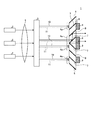
図2は、本実施例1の変形例に係る光源装置の概略構成を示す図である。図3は、図2に示す偏光変換素子3の正面図である。本変形例1では、光源装置1が複数のレーザー光源2をアレイ状に備える。これら複数のレーザー光源2は、それぞれのレーザー光源2から射出されるレーザー光の偏光方向が、第1の偏光方向に揃うように配置される。
FIG. 2 is a diagram illustrating a schematic configuration of a light source device according to a modification of the first embodiment. FIG. 3 is a front view of the polarization conversion element 3 shown in FIG. In the first modification, the
また、偏光変換素子4も複数の基部6がアレイ状に並列されるとともに、互いに接着される。そして、基部6の接着面には、交互に偏光分離素子7と反射ミラー8が蒸着形成される。この構成により、偏光変換素子4には、複数の光の入射領域4aが構成される。また、複数の偏光回転素子9が、偏光分離素子7を透過した光が射出される位置に設けられる。
Also, the polarization conversion element 4 has a plurality of
本変形例では、図示しないインテグレーターレンズにより、散乱素子3から射出された光を分割し、偏光変換素子4の複数の入射領域4aに入射させる。そして、偏光変換素子4に入射した光は、その偏光方向が第1の偏光方向に揃えられて射出される。
In this modification, the light emitted from the scattering element 3 is divided by an integrator lens (not shown) and is incident on the plurality of
このように、レーザー光源2を複数備えることで、光源装置1から射出される光の光量を増加させることができる。また、偏光変換素子4を、複数の基部6を並列させて構成することで、入射領域4aを増やすことができ、光束の広がりにも対応できるようになる。また、複数の偏光回転素子9が設けられるので、1つの偏光回転素子9が変換を担当する光の光量を抑えて、偏光回転素子9や接着材の劣化を抑えることができる。これにより、より信頼性の高い光源装置1とすることもできる。
As described above, by providing a plurality of
なお、基部6同士の接合面にも接着材が用いられているが、熱膨張率の異なる基部6と偏光回転素子9とを接着するための接着材よりも、その使用量や厚さが小さくて済むため、劣化の影響も比較的少なくて済む。
In addition, although the adhesive material is used also in the joint surface of the
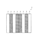
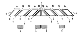
図4は、偏光変換素子4の分解図である。図4に示すように、並列される基部6のうち、その一面が光の入射領域4aとなる基部6に偏光分離素子7や反射ミラー8を蒸着させるように構成すれば、偏光分離素子7側の接着材12には、第2の偏光方向の偏光成分の光だけが照射されるし、反射ミラー8側の接着材13には、光がほとんど照射されない。そのため、基部6同士を接着させる接着材12,13の劣化も抑えることができる。また、第2の偏光方向の偏光成分を低減することで、接着材12の劣化をさらに抑えることができる。
FIG. 4 is an exploded view of the polarization conversion element 4. As shown in FIG. 4, if the
図5は、本発明の実施例2に係るプロジェクター60の概略構成図である。本実施例に係るプロジェクター60は、実施例1に係る光源装置1と同様に構成された光源装置61を有する。光源装置61は、赤色(R)光、緑色(G)光、青色(B)光を含む光を射出する。例えば、レーザー光源2として青色レーザー、散乱素子3として赤色と緑色の帯域を発光する蛍光体を含んだ樹脂層を用いれば、最小の構成で光の3原色を再現できる。
FIG. 5 is a schematic configuration diagram of a
均一化光学系64は、光源装置61から入射した光の強度分布を均一化させる光学系であって、例えばロッドインテグレーターを有する。ダイクロイックミラー65は、均一化光学系64からの光のうちB光を透過させ、R光及びG光を反射する。ダイクロイックミラー66は、R光を透過させ、G光を反射する。ダイクロイックミラー65、66は、光源装置61からの光を色ごとに分離する色分離光学系として機能する。
The homogenizing
ダイクロイックミラー66を透過したR光は、反射ミラー67、68で反射した後、R光用の空間光変調装置70Rへ入射する。空間光変調装置70Rは、R光を画像信号に応じて変調する。ダイクロイックミラー66で反射したG光は、G光用の空間光変調装置70Gへ入射する。空間光変調装置70Gは、G光を画像信号に応じて変調する。ダイクロイックミラー65を透過したB光は、反射ミラー69で反射した後、B光用の空間光変調装置70Bへ入射する。空間光変調装置70R、70G、70Bは、例えば、透過型の液晶表示装置である。
The R light transmitted through the
色合成光学系であるクロスダイクロイックプリズム71は、空間光変調装置70R、70G、70Bでそれぞれ変調された各色光を合成する。投写光学系72は、クロスダイクロイックプリズム71で合成された各色光をスクリーン73へ投写する。プロジェクター60は、光源装置61を用いることで偏光回転素子の劣化の抑制を図ることができ、信頼性を向上させて、高品質な画像を得ることが可能となる。
A cross
また、均一化光学系64としてロッドインテグレーターを用いたが、マルチレンズアレイを用いても良い。また、均一化光学系64を省いた構成や、光源装置61に均一化光学系64を内蔵した構成でも良い。
Moreover, although the rod integrator is used as the uniformizing
プロジェクターは、3色に対して、3個の透過型の空間光変調装置を用いた図5の構成に限定されない。色は2色以下でも4色以上でもよい。空間光変調装置の数と色数が同数である必要はなく、例えば微小な複数色のカラーフィルターを有する1個の空間光変調装置に、2色以上の光を入射してもよい。また、空間光変調装置としては、透過型も、反射型も用いることができる。構成によっては、色分離光学系や色合成光学系を省くこともできる。 The projector is not limited to the configuration shown in FIG. 5 using three transmissive spatial light modulators for three colors. The color may be 2 colors or less or 4 colors or more. The number of spatial light modulators and the number of colors do not have to be the same. For example, two or more colors of light may be incident on one spatial light modulator having a plurality of minute color filters. As the spatial light modulator, a transmission type or a reflection type can be used. Depending on the configuration, the color separation optical system and the color synthesis optical system can be omitted.
以上のように、本発明に係る光源装置及びプロジェクターは、レーザー光を用いて画像を表示する場合に有用である。 As described above, the light source device and the projector according to the present invention are useful when displaying an image using laser light.
1 光源装置、2 レーザー光源、3 散乱素子、4 偏光変換素子、4a 入射領域、5 コリメート光学系、6 基部、7 偏光分離素子、8 反射ミラー、9 偏光回転素子、10,11 矢印、12,13 接着材、60 プロジェクター、61 光源装置、64 均一化光学系、65,66 ダイクロイックミラー、67,68,69 反射ミラー、70R,70G,70B 空間光変調装置、71 クロスダイクロイックプリズム、72 投写光学系、73 スクリーン
DESCRIPTION OF
Claims (6)
前記光を散乱させる散乱素子と、
前記第1の偏光方向と略垂直な第2の偏光方向の偏光成分を、前記散乱素子から射出された散乱光から分離する偏光分離素子と、
前記偏光分離素子で分離された前記第2の偏光方向の偏光成分が通過する光路上に設けられ、前記第2の偏光方向の偏光成分を前記第1の偏光方向に変換させる偏光回転素子と、を備えることを特徴とする光源装置。 A light source that emits light whose polarization components are aligned in the first polarization direction;
A scattering element for scattering the light ;
A polarization separation element that separates a polarization component in a second polarization direction substantially perpendicular to the first polarization direction from scattered light emitted from the scattering element;
A polarization rotation element that is provided on an optical path through which the polarization component of the second polarization direction separated by the polarization separation element passes, and that converts the polarization component of the second polarization direction into the first polarization direction; A light source device comprising:
前記偏光回転素子は、無機材料で構成されることを特徴とする請求項1または2に記載の光源装置。 Further comprising a base to which the polarization rotation element is adhered by an adhesive;
The light source device according to claim 1, wherein the polarization rotation element is made of an inorganic material.
前記光源装置から射出した光を画像信号に応じて変調する空間光変調装置と、を有することを特徴とするプロジェクター。 A light source device according to any one of claims 1 to 5 ,
And a spatial light modulator that modulates light emitted from the light source device in accordance with an image signal.
Priority Applications (5)
| Application Number | Priority Date | Filing Date | Title |
|---|---|---|---|
| JP2010138001A JP5459092B2 (en) | 2010-06-17 | 2010-06-17 | Light source device and projector |
| US13/114,522 US9134542B2 (en) | 2010-06-17 | 2011-05-24 | Light source device and projector |
| CN201410759204.3A CN104360490A (en) | 2010-06-17 | 2011-06-17 | Light source device and projector |
| CN2011101634496A CN102289077A (en) | 2010-06-17 | 2011-06-17 | Light source device and projector |
| CN201410749420.XA CN104375279B (en) | 2010-06-17 | 2011-06-17 | Projector |
Applications Claiming Priority (1)
| Application Number | Priority Date | Filing Date | Title |
|---|---|---|---|
| JP2010138001A JP5459092B2 (en) | 2010-06-17 | 2010-06-17 | Light source device and projector |
Publications (3)
| Publication Number | Publication Date |
|---|---|
| JP2012003042A JP2012003042A (en) | 2012-01-05 |
| JP2012003042A5 JP2012003042A5 (en) | 2013-12-05 |
| JP5459092B2 true JP5459092B2 (en) | 2014-04-02 |
Family
ID=45328358
Family Applications (1)
| Application Number | Title | Priority Date | Filing Date |
|---|---|---|---|
| JP2010138001A Active JP5459092B2 (en) | 2010-06-17 | 2010-06-17 | Light source device and projector |
Country Status (3)
| Country | Link |
|---|---|
| US (1) | US9134542B2 (en) |
| JP (1) | JP5459092B2 (en) |
| CN (3) | CN104360490A (en) |
Families Citing this family (23)
| Publication number | Priority date | Publication date | Assignee | Title |
|---|---|---|---|---|
| JP2013162020A (en) | 2012-02-07 | 2013-08-19 | Seiko Epson Corp | Wavelength conversion element, light source device, and projector |
| JP2013162021A (en) * | 2012-02-07 | 2013-08-19 | Seiko Epson Corp | Wavelength conversion element, light source device, and projector |
| JP6290523B2 (en) * | 2012-03-02 | 2018-03-07 | セイコーエプソン株式会社 | projector |
| CN102722074B (en) * | 2012-03-02 | 2015-07-29 | 深圳市光峰光电技术有限公司 | Polarized light light-emitting device, light-emitting device and projector |
| JP2013228530A (en) * | 2012-04-25 | 2013-11-07 | Seiko Epson Corp | Projector |
| JP5970994B2 (en) | 2012-07-12 | 2016-08-17 | ソニー株式会社 | Light source device and projector |
| EP2971948A1 (en) * | 2013-03-15 | 2016-01-20 | Dolby Laboratories Licensing Corporation | Apparatus for display systems |
| JP6136744B2 (en) * | 2013-08-15 | 2017-05-31 | ソニー株式会社 | Light source device and image display device |
| KR101574285B1 (en) * | 2013-12-16 | 2015-12-03 | 유한회사 마스터이미지쓰리디아시아 | A stereoscopic image projection device for improved brightness and a providing method for A stereoscopic image |
| JP6187276B2 (en) * | 2014-01-20 | 2017-08-30 | ソニー株式会社 | Light source device and image display device |
| CN106162116B (en) * | 2015-04-09 | 2018-03-20 | 深圳市光峰光电技术有限公司 | Projection display system and its control method |
| WO2016189582A1 (en) | 2015-05-22 | 2016-12-01 | Necディスプレイソリューションズ株式会社 | Lighting device, projector, display system and light source adjustment method |
| CN106468792B (en) * | 2015-08-19 | 2019-09-10 | 扬明光学股份有限公司 | Optical devices |
| WO2017208572A1 (en) * | 2016-05-30 | 2017-12-07 | ソニー株式会社 | Image display device and light source device |
| JP6176371B2 (en) * | 2016-07-12 | 2017-08-09 | ソニー株式会社 | projector |
| JP6332485B2 (en) * | 2017-01-25 | 2018-05-30 | セイコーエプソン株式会社 | projector |
| CN106953999A (en) * | 2017-04-17 | 2017-07-14 | 苏州佳世达电通有限公司 | Scanning means |
| JP6418289B2 (en) * | 2017-07-07 | 2018-11-07 | ソニー株式会社 | projector |
| CN108226161B (en) * | 2018-01-15 | 2019-12-17 | 天津大学 | System and method for removing speckle phenomenon in laser shadow method test |
| JP7081256B2 (en) * | 2018-03-27 | 2022-06-07 | セイコーエプソン株式会社 | Optical unit and display device |
| CN108564800B (en) * | 2018-06-13 | 2020-08-14 | 东莞市雍华昊信息技术有限公司 | Intelligent auxiliary reminding equipment for traffic signal lamp and working method thereof |
| JP6973457B2 (en) * | 2019-09-20 | 2021-12-01 | セイコーエプソン株式会社 | projector |
| WO2024065695A1 (en) * | 2022-09-30 | 2024-04-04 | Beijing Asu Tech Co.Ltd. | Polarization light source apparatus |
Family Cites Families (16)
| Publication number | Priority date | Publication date | Assignee | Title |
|---|---|---|---|---|
| KR20020084155A (en) | 2001-02-27 | 2002-11-04 | 세이코 엡슨 가부시키가이샤 | Illumination optical system and projector using the same |
| JP2003021800A (en) * | 2001-07-10 | 2003-01-24 | Canon Inc | Projection type display device |
| JP2003302523A (en) | 2002-04-10 | 2003-10-24 | Nippon Shinku Kagaku Kenkyusho:Kk | Polarization converting element and liquid crystal display device using the same |
| TWI235263B (en) * | 2002-05-14 | 2005-07-01 | Sony Corp | Illuminating optical system, image display unit and method of illuminating space modulation element |
| US20040159900A1 (en) * | 2003-01-27 | 2004-08-19 | 3M Innovative Properties Company | Phosphor based light sources having front illumination |
| CN100373643C (en) * | 2003-01-27 | 2008-03-05 | 3M创新有限公司 | Phosphor based light sources having a polymeric long pass reflector |
| JP4194548B2 (en) * | 2004-11-10 | 2008-12-10 | 三洋電機株式会社 | Illumination device and projection display device |
| US7434945B2 (en) * | 2004-11-10 | 2008-10-14 | Sanyo Electric Co., Ltd. | Illuminating device and projection type video display apparatus |
| JP4401348B2 (en) * | 2004-12-28 | 2010-01-20 | シャープ株式会社 | LIGHT EMITTING DEVICE AND LIGHTING DEVICE AND DISPLAY DEVICE USING THE SAME |
| JP4821204B2 (en) * | 2005-07-22 | 2011-11-24 | セイコーエプソン株式会社 | LIGHTING DEVICE, IMAGE DISPLAY DEVICE, AND PROJECTOR |
| US7547114B2 (en) * | 2007-07-30 | 2009-06-16 | Ylx Corp. | Multicolor illumination device using moving plate with wavelength conversion materials |
| JP2009092730A (en) * | 2007-10-04 | 2009-04-30 | Epson Toyocom Corp | Polarization conversion element |
| JP2009216822A (en) * | 2008-03-07 | 2009-09-24 | Seiko Epson Corp | Display device and electronic apparatus |
| JP4662185B2 (en) | 2008-05-15 | 2011-03-30 | カシオ計算機株式会社 | Light source device and projector |
| JP5381363B2 (en) * | 2008-09-01 | 2014-01-08 | セイコーエプソン株式会社 | projector |
| JP5152586B2 (en) * | 2008-09-30 | 2013-02-27 | カシオ計算機株式会社 | Light source device and projector |
-
2010
- 2010-06-17 JP JP2010138001A patent/JP5459092B2/en active Active
-
2011
- 2011-05-24 US US13/114,522 patent/US9134542B2/en active Active
- 2011-06-17 CN CN201410759204.3A patent/CN104360490A/en active Pending
- 2011-06-17 CN CN2011101634496A patent/CN102289077A/en active Pending
- 2011-06-17 CN CN201410749420.XA patent/CN104375279B/en active Active
Also Published As
| Publication number | Publication date |
|---|---|
| CN104360490A (en) | 2015-02-18 |
| CN104375279A (en) | 2015-02-25 |
| US9134542B2 (en) | 2015-09-15 |
| CN102289077A (en) | 2011-12-21 |
| JP2012003042A (en) | 2012-01-05 |
| US20110310349A1 (en) | 2011-12-22 |
| CN104375279B (en) | 2017-07-25 |
Similar Documents
| Publication | Publication Date | Title |
|---|---|---|
| JP5459092B2 (en) | Light source device and projector | |
| JP6812716B2 (en) | Lighting equipment and projector | |
| US9939718B2 (en) | Light source apparatus and projector | |
| JP6019891B2 (en) | Light source device and projector | |
| US6910772B2 (en) | Image display apparatus | |
| JP6874743B2 (en) | Light source device and projector | |
| JP2014119471A (en) | Light source device and projector | |
| JP2010204333A (en) | Projector | |
| JP6747066B2 (en) | Wavelength conversion element, lighting device and projector | |
| JP7247776B2 (en) | Light source device and projector | |
| WO2002001289A1 (en) | Projector | |
| CN114563906B (en) | Light source optical system, light source unit, light source device, and image display device | |
| JP6269037B2 (en) | Fluorescent light emitting device, light source device and projector | |
| JP2018146951A (en) | Projection-type image display device | |
| JP5423442B2 (en) | Lighting device and projector | |
| JP2009103863A (en) | Retardation plate and projector | |
| US6722768B1 (en) | Projector | |
| JP6197361B2 (en) | projector | |
| JP2020187228A (en) | Wavelength conversion complex, fluorescent plate, fluorescent wheel, light source device, projection-type image display device, and the method for producing the wavelength conversion complex | |
| JP2013200374A (en) | Image display apparatus | |
| US11333962B2 (en) | Light source apparatus and projector | |
| JP6888637B2 (en) | Light source device, projector and phosphor rod | |
| JP2009128568A (en) | Polarization conversion element and projector | |
| JP2017181602A (en) | Light source unit | |
| JP2017044766A (en) | projector |
Legal Events
| Date | Code | Title | Description |
|---|---|---|---|
| A621 | Written request for application examination |
Free format text: JAPANESE INTERMEDIATE CODE: A621 Effective date: 20130328 |
|
| A521 | Written amendment |
Free format text: JAPANESE INTERMEDIATE CODE: A523 Effective date: 20131021 |
|
| A977 | Report on retrieval |
Free format text: JAPANESE INTERMEDIATE CODE: A971007 Effective date: 20131212 |
|
| TRDD | Decision of grant or rejection written | ||
| A01 | Written decision to grant a patent or to grant a registration (utility model) |
Free format text: JAPANESE INTERMEDIATE CODE: A01 Effective date: 20131217 |
|
| A61 | First payment of annual fees (during grant procedure) |
Free format text: JAPANESE INTERMEDIATE CODE: A61 Effective date: 20131230 |
|
| R150 | Certificate of patent or registration of utility model |
Ref document number: 5459092 Country of ref document: JP Free format text: JAPANESE INTERMEDIATE CODE: R150 Free format text: JAPANESE INTERMEDIATE CODE: R150 |
|
| S531 | Written request for registration of change of domicile |
Free format text: JAPANESE INTERMEDIATE CODE: R313531 |
|
| R350 | Written notification of registration of transfer |
Free format text: JAPANESE INTERMEDIATE CODE: R350 |