JP5457820B2 - Roll stamper - Google Patents
Roll stamper Download PDFInfo
- Publication number
- JP5457820B2 JP5457820B2 JP2009290928A JP2009290928A JP5457820B2 JP 5457820 B2 JP5457820 B2 JP 5457820B2 JP 2009290928 A JP2009290928 A JP 2009290928A JP 2009290928 A JP2009290928 A JP 2009290928A JP 5457820 B2 JP5457820 B2 JP 5457820B2
- Authority
- JP
- Japan
- Prior art keywords
- sleeve
- mandrel
- diameter
- roll stamper
- pores
- Prior art date
- Legal status (The legal status is an assumption and is not a legal conclusion. Google has not performed a legal analysis and makes no representation as to the accuracy of the status listed.)
- Active
Links
Images


Classifications
-
- F—MECHANICAL ENGINEERING; LIGHTING; HEATING; WEAPONS; BLASTING
- F16—ENGINEERING ELEMENTS AND UNITS; GENERAL MEASURES FOR PRODUCING AND MAINTAINING EFFECTIVE FUNCTIONING OF MACHINES OR INSTALLATIONS; THERMAL INSULATION IN GENERAL
- F16C—SHAFTS; FLEXIBLE SHAFTS; ELEMENTS OR CRANKSHAFT MECHANISMS; ROTARY BODIES OTHER THAN GEARING ELEMENTS; BEARINGS
- F16C13/00—Rolls, drums, discs, or the like; Bearings or mountings therefor
Description
本発明は、外周面に形成された微細凹凸構造を被転写体に転写するロールスタンパに関する。 The present invention relates to a roll stamper that transfers a fine concavo-convex structure formed on an outer peripheral surface to a transfer target.
可視光波長以下の周期の微細凹凸構造を表面に有する光学フィルムは、反射防止機能等を発現することから、その有用性が注目されている。特に、モスアイ(Moth−Eye)構造と呼ばれる微細凹凸構造は、空気の屈折率から材料の屈折率に連続的に増大していくことで有効な反射防止機能を発現することが知られている。 An optical film having a fine concavo-convex structure with a period of less than or equal to the wavelength of visible light on the surface exhibits an antireflection function and the like, and thus its usefulness has attracted attention. In particular, it is known that a fine concavo-convex structure called a moth-eye structure exhibits an effective antireflection function by continuously increasing from a refractive index of air to a refractive index of a material.
微細凹凸構造を表面に有する光学フィルムの製造方法としては、基材フィルム(被転写体)の表面に、スタンパの表面に形成された微細凹凸構造を転写するインプリント法が挙げられる。該インプリント法としては、例えば、下記の方法が知られている(特許文献1)。
複数の細孔を有する陽極酸化アルミナが表面に形成されたロールスタンパと、透明な基材フィルムとの間に、紫外線硬化性樹脂が介在した状態で、紫外線硬化性樹脂に紫外線を照射し、紫外線硬化性樹脂を硬化させた後、硬化樹脂とともに基材フィルムをロールスタンパから剥離する光インプリント法。
Examples of the method for producing an optical film having a fine concavo-convex structure on the surface include an imprint method in which the fine concavo-convex structure formed on the surface of the stamper is transferred to the surface of the base film (transfer object). As the imprint method, for example, the following method is known (Patent Document 1).
An ultraviolet curable resin is irradiated with ultraviolet rays in a state where the ultraviolet curable resin is interposed between a roll stamper having a plurality of pores having anodized alumina formed on the surface and a transparent base film, An optical imprint method in which a base film is peeled off from a roll stamper together with a cured resin after the curable resin is cured.
該ロールスタンパは、中空円柱状のアルミニウム基材の外周面に、複数の細孔を有する陽極酸化アルミナが形成されたスリーブを、円柱状のマンドレル(軸芯)の外周に装着したものである。
該ロールスタンパにおいては、スリーブとマンドレルとの隙間は、スリーブのがたつきを抑えるため、30〜160μm程度とされる。また、アルミニウム基材の外周面に、規則性が高く、かつサイズのばらつきの小さい複数の細孔を有する陽極酸化アルミナを形成するためには、アルミニウム基材として純アルミニウム(純度99%以上)のものを用いる必要がある。
In the roll stamper, a sleeve in which anodized alumina having a plurality of pores is formed on the outer peripheral surface of a hollow cylindrical aluminum base is mounted on the outer periphery of a cylindrical mandrel (shaft core).
In the roll stamper, the gap between the sleeve and the mandrel is set to about 30 to 160 μm in order to suppress the shakiness of the sleeve. In addition, in order to form anodized alumina having a plurality of pores with high regularity and small size variation on the outer peripheral surface of an aluminum substrate, pure aluminum (purity 99% or more) is used as the aluminum substrate. It is necessary to use something.
しかし、純アルミニウムは、アルミニウム合金に比べ柔らかいため、ロールスタンパの大面積化のためにスリーブを長くしたり、スリーブの軽量化のためにスリーブを肉薄にしたりすると、中空円柱状のスリーブの中心軸が曲がりやすくなる。
そして、スリーブとマンドレルとの隙間が30〜160μm程度しかないため、スリーブの中心軸がわずかにでも曲がってしまうと、スリーブをマンドレルに装着できなくなるという問題が生じる。
However, since pure aluminum is softer than aluminum alloy, if the sleeve is lengthened to increase the roll stamper area or thinned to reduce the weight of the sleeve, the central axis of the hollow cylindrical sleeve Becomes easier to bend.
Since the gap between the sleeve and the mandrel is only about 30 to 160 μm, if the central axis of the sleeve is slightly bent, there arises a problem that the sleeve cannot be attached to the mandrel.
本発明は、スリーブのマンドレルへの装着性が良好であり、かつスリーブのがたつきが抑えられたロールスタンパを提供する。 The present invention provides a roll stamper in which the sleeve can be easily attached to a mandrel and the sleeve can be prevented from rattling.
本発明のロールスタンパは、マンドレルと、該マンドレルの外周に着脱可能に装着される中空円柱状のスリーブとを有し、該スリーブの外周面に形成された微細凹凸構造を被転写体に転写するロールスタンパであって、前記マンドレルが、前記スリーブの軸方向一方の端部の開口部に対応する部分の外径よりも、前記スリーブの軸方向他方の開口部に対応する部分の外径が大きくされ、前記スリーブと前記マンドレルとの隙間が、前記スリーブの両端の開口部よりも、これらの間の中間部において広くされていることを特徴とする。 Roll stamper of the present invention, the Ma Ndoreru, and a hollow cylindrical sleeve which is detachably attached to the outer periphery of the mandrel, the fine unevenness formed on the outer peripheral surface of the sleeve on the transfer member a roll stamper for transferring the mandrel, than the outer diameter of the portion corresponding to the opening in the one axial end portion of the front Symbol sleeve, corresponding to the opening in the other axial pre Symbol sleeve The outer diameter of the part is increased, and the gap between the sleeve and the mandrel is made wider at the intermediate part between the openings than at both ends of the sleeve.
前記スリーブは、純度99%以上のアルミニウムからなる中空円柱状のアルミニウム基材の外周面に、複数の細孔を有する陽極酸化アルミナが形成されたものであることが好ましい。
前記スリーブの両端の開口部における前記スリーブと前記マンドレルとの隙間は、40〜120μmであることが好ましい。
前記ロールスタンパは、前記中間部において、前記スリーブと前記マンドレルとの隙間に温調水が流通されることが好ましい。
The sleeve is preferably formed by forming anodized alumina having a plurality of pores on the outer peripheral surface of a hollow cylindrical aluminum base material made of aluminum having a purity of 99% or more.
The gap between the sleeve and the mandrel at the openings at both ends of the sleeve is preferably 40 to 120 μm.
In the roll stamper, it is preferable that temperature-controlled water is circulated in a gap between the sleeve and the mandrel at the intermediate portion.
本発明のロールスタンパは、スリーブのマンドレルへの装着性が良好であり、かつスリーブのがたつきが抑えられたものとなる。 The roll stamper of the present invention has a good mounting property of the sleeve to the mandrel and suppresses the rattling of the sleeve.
(ロールスタンパ)
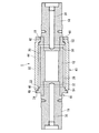
図1は、本発明のロールスタンパの一例を示す断面図である。ロールスタンパ1は、円柱状のマンドレル10と、該マンドレル10の先端側から基端側に向かって該マンドレル10の外周に着脱可能に装着される中空円柱状のスリーブ40と、マンドレル10の先端側のスリーブ40の端部に当接する、スリーブ40の抜けを防止するための締め付けネジ60とを有するものである。
(Roll stamper)
FIG. 1 is a cross-sectional view showing an example of a roll stamper of the present invention. The
マンドレル10は、図1および図2に示すように、中空円柱状のマンドレル本体部12と、マンドレル本体部12の開口部に一方の端部が挿入され、マンドレル本体部12からマンドレル10の先端側に向かって延びる円柱状の軸受け部14と、マンドレル本体部12の開口部に一方の端部が挿入され、マンドレル本体部12からマンドレル10の基端側に向かって延びる円柱状の軸受け部16とを有する。
As shown in FIGS. 1 and 2, the
マンドレル本体部12は、マンドレル10の先端側から順に、マンドレル10の先端側にあるスリーブ40の小径開口部42と略嵌合する小径部18と、小径部18よりも外径が大きくされたマンドレル中間部20と、マンドレル10の基端側にあるスリーブ40の大径開口部46と略嵌合する、マンドレル中間部20よりも外径が大きくされた大径部22と、マンドレル10の基端側にあるスリーブ40のフランジ受け部48と略嵌合する、大径部22よりも外径が大きくされたフランジ部24とを有する。
The mandrel
マンドレル中間部20は、温調水を充填する空間26が形成されている。また、図3に示すように、マンドレル10の先端側の空間26の端部には、温調水導入孔30が複数穿設され(図示では1ヶ所)、マンドレル10の基端側の空間26の端部には、温調水導出孔32が複数穿設されている。
The
軸受け部14および軸受け部16の外径は、マンドレル本体部12の小径部18よりも小さくされている。
軸受け部14には、中心軸に沿って延びる温調水供給孔34が穿設され、該温調水供給孔34の終端は、マンドレル中間部20の温調水導入孔30に連通している。また、軸受け部16には、中心軸に沿って延びる温調水排出孔36が穿設され、該温調水排出孔36の始端は、マンドレル中間部20の温調水導出孔32に連通している。
The outer diameters of the
A temperature adjustment
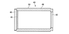
スリーブ40は、図1および図4に示すように、マンドレル10の先端側から順に、マンドレル本体部12の小径部18と略嵌合する小径開口部42と、小径開口部42よりも内径が大きくされたスリーブ中間部44と、マンドレル本体部12の大径部22と略嵌合する、スリーブ中間部44よりも内径が大きくされた大径開口部46と、マンドレル本体部12のフランジ部24と略嵌合する、大径開口部46よりも内径が大きくされたフランジ受け部48とを有する。
スリーブ中間部44は、スリーブ40の両端部よりも外径が大きくされ、スリーブ中間部44の外周面50には、微細凹凸構造が形成されている。
As shown in FIGS. 1 and 4, the
The sleeve
スリーブ40においては、マンドレル10の先端側から基端側に向かって段階的に内径が大きくされ、これに対応して、マンドレル10においても、マンドレル10の先端側から基端側に向かって段階的に外径が大きくされ、結果的に、マンドレル10の先端側にあるスリーブ40の開口部(小径開口部42)に対応する部分(小径部18)の外径よりも、マンドレル10の基端側にあるスリーブ40の開口部(大径開口部46およびフランジ受け部48)に対応する部分(大径部22およびフランジ部24)の外径が大きくされている。このような基端側から先端側に向かって縮径する構造によって、スリーブ40のマンドレル10への装着およびマンドレル10からの取り外しが容易となる。
In the
また、スリーブ40とマンドレル10との隙間が、スリーブ40の小径開口部42および大径開口部46よりも、これらの間のスリーブ中間部44において広くされている。スリーブ40とマンドレル10との隙間がスリーブ中間部44において広くされていることによって、ロールスタンパ1の大面積化のためにスリーブ40を長くしたり、スリーブ40の軽量化のためにスリーブ40を肉薄にしたりした際に、スリーブ40の中心軸が曲がったとしても、スリーブ40のマンドレル10への装着が可能である。
Further, the gap between the
また、スリーブ40とマンドレル10との隙間が、スリーブ中間部44よりも、これらの両側のスリーブ40の小径開口部42および大径開口部46において狭くされていることによって、スリーブ40の両端の開口部においてスリーブ40とマンドレル10とがほぼ嵌合に近い状態となり、スリーブ40のがたつきが抑えられる。
Further, the gap between the
スリーブ40の小径開口部42、大径開口部46およびフランジ受け部48におけるスリーブ40とマンドレル10との隙間は、40〜120μmであることが好ましく、40〜80μmであることがより好ましい。該隙間が40μm以上であれば、スリーブ40のマンドレル10への装着およびマンドレル10からの取り外しがさらに容易となる。該隙間が120μm以下であれば、スリーブ40のがたつきが充分に抑えられる。なお、スリーブ40の両端の開口部においてスリーブ40とマンドレル10との間に若干の隙間があっても、スリーブ40の両端の開口部においてスリーブ40とマンドレル10との間にOリング52、Oリング54が介在しているため、マンドレル中間部20の温調水の空間26を流れる温調水が、該隙間から流れ出ることはない。
The gap between the
(スリーブの製造方法)
スリーブ40としては、純度99%以上のアルミニウムからなる中空円柱状のアルミニウム基材の外周面に、複数の細孔を有する陽極酸化アルミナ(アルミニウムの酸化皮膜(アルマイト))が形成されたものが好ましい。以下、該スリーブ40の製造方法の一例について説明する。
(Sleeve manufacturing method)
The
スリーブ40の製造方法としては、大面積化が可能であり、かつ作製が簡便である点から、下記の工程(a)〜(f)を有する方法が好ましい。
(a)中空円柱状のアルミニウム基材を電解液中、定電圧下で陽極酸化して、外周面に酸化皮膜を形成する工程。
(b)酸化皮膜を除去し、陽極酸化の細孔発生点を形成する工程。
(c)前記工程(b)の後、電解液中、再度陽極酸化し、細孔発生点に細孔を有する酸化皮膜を形成する工程。
(d)前記工程(c)の後、細孔の径を拡大させる工程。
(e)前記工程(d)の後、電解液中、再度陽極酸化する工程。
(f)前記工程(d)と工程(e)を繰り返し行う工程。
As a manufacturing method of the
(A) A step of forming an oxide film on the outer peripheral surface by anodizing a hollow cylindrical aluminum base material in an electrolytic solution under a constant voltage.
(B) A step of removing the oxide film and forming pore generation points for anodic oxidation.
(C) A step of anodizing again in the electrolytic solution after the step (b) to form an oxide film having pores at the pore generation points.
(D) A step of enlarging the diameter of the pores after the step (c).
(E) A step of anodizing again in the electrolytic solution after the step (d).
(F) A step of repeatedly performing the step (d) and the step (e).
工程(a):
図5に示すように、アルミニウム基材64を陽極酸化すると、細孔66を有する酸化皮膜68が形成される。アルミニウムの純度は、99%以上であり、99.5%以上が好ましく、99.8%以上がより好ましい。アルミニウムの純度が低いと、陽極酸化した時に、不純物の偏析により可視光線を散乱する大きさの凹凸構造が形成されたり、陽極酸化で得られる細孔の規則性が低下したりする。電解液としては、シュウ酸、硫酸等が挙げられる。
Step (a):
As shown in FIG. 5, when the
<シュウ酸を電解液として用いる場合>
シュウ酸の濃度は、0.7M以下が好ましい。シュウ酸の濃度が0.7Mを超えると、電流値が高くなりすぎて酸化皮膜の表面が粗くなることがある。
化成電圧が30〜60Vの時、周期が100nmの規則性の高い細孔を有する陽極酸化アルミナを得ることができる。化成電圧がこの範囲より高くても低くても規則性が低下する傾向にある。
電解液の温度は、60℃以下が好ましく、45℃以下がより好ましい。電解液の温度が60℃を超えると、いわゆる「ヤケ」といわれる現象がおこり、細孔が壊れたり、表面が溶けて細孔の規則性が乱れたりすることがある。
<When oxalic acid is used as the electrolyte>
The concentration of oxalic acid is preferably 0.7 M or less. When the concentration of oxalic acid exceeds 0.7M, the current value becomes too high, and the surface of the oxide film may become rough.
When the formation voltage is 30 to 60 V, anodized alumina having highly regular pores with a period of 100 nm can be obtained. Regardless of whether the formation voltage is higher or lower than this range, the regularity tends to decrease.
The temperature of the electrolytic solution is preferably 60 ° C. or lower, and more preferably 45 ° C. or lower. When the temperature of the electrolytic solution exceeds 60 ° C., a so-called “burn” phenomenon occurs, and the pores may be broken, or the surface may melt and the regularity of the pores may be disturbed.
<硫酸を電解液として用いる場合>
硫酸の濃度は0.7M以下が好ましい。硫酸の濃度が0.7Mを超えると、電流値が高くなりすぎて定電圧を維持できなくなることがある。
化成電圧が25〜30Vの時、周期が63nmの規則性の高い細孔を有する陽極酸化アルミナを得ることができる。化成電圧がこの範囲より高くても低くても規則性が低下する傾向がある。
電解液の温度は、30℃以下が好ましく、20℃以下がよりに好ましい。電解液の温度が30℃を超えると、いわゆる「ヤケ」といわれる現象がおこり、細孔が壊れたり、表面が溶けて細孔の規則性が乱れたりすることがある。
<When sulfuric acid is used as the electrolyte>
The concentration of sulfuric acid is preferably 0.7M or less. If the concentration of sulfuric acid exceeds 0.7M, the current value may become too high to maintain a constant voltage.
When the formation voltage is 25 to 30 V, anodized alumina having highly regular pores with a period of 63 nm can be obtained. The regularity tends to decrease whether the formation voltage is higher or lower than this range.
The temperature of the electrolytic solution is preferably 30 ° C. or lower, and more preferably 20 ° C. or lower. When the temperature of the electrolytic solution exceeds 30 ° C., a so-called “burn” phenomenon occurs, and the pores may be broken or the surface may melt and the regularity of the pores may be disturbed.
工程(b):
図5に示すように、酸化皮膜68を一旦除去し、これを陽極酸化の細孔発生点70にすることで細孔の規則性を向上することができる。
Step (b):
As shown in FIG. 5, the regularity of the pores can be improved by once removing the
酸化皮膜を除去する方法としては、アルミニウムを溶解せず、酸化皮膜を選択的に溶解する溶液に溶解させて除去する方法が挙げられる。このような溶液としては、例えば、クロム酸/リン酸混合液等が挙げられる。 Examples of the method for removing the oxide film include a method in which aluminum is not dissolved but is dissolved in a solution that selectively dissolves the oxide film and removed. Examples of such a solution include a chromic acid / phosphoric acid mixed solution.
工程(c):
図5に示すように、酸化皮膜を除去したアルミニウム基材64を再度、陽極酸化すると、円柱状の細孔66を有する酸化皮膜68が形成される。
陽極酸化は、工程(a)と同様な条件で行えばよい。陽極酸化の時間を長くするほど深い細孔を得ることができる。
Step (c):
As shown in FIG. 5, when the
Anodization may be performed under the same conditions as in step (a). Deeper pores can be obtained as the anodic oxidation time is lengthened.
工程(d):
図5に示すように、細孔66の径を拡大させる処理(以下、細孔径拡大処理と記す。)を行う。細孔径拡大処理は、酸化皮膜を溶解する溶液に浸漬して陽極酸化で得られた細孔の径を拡大させる処理である。このような溶液としては、例えば、5質量%程度のリン酸水溶液等が挙げられる。
細孔径拡大処理の時間を長くするほど、細孔径は大きくなる。
Step (d):
As shown in FIG. 5, a process for expanding the diameter of the pore 66 (hereinafter referred to as a pore diameter expanding process) is performed. The pore diameter expansion treatment is a treatment for expanding the diameter of the pores obtained by anodic oxidation by immersing in a solution dissolving the oxide film. Examples of such a solution include a phosphoric acid aqueous solution of about 5% by mass.
The longer the pore diameter expansion processing time, the larger the pore diameter.
工程(e):
図5に示すように、再度、陽極酸化すると、円柱状の細孔66の底部から下に延びる、直径の小さい円柱状の細孔66がさらに形成される。
陽極酸化は、工程(a)と同様な条件で行えばよい。陽極酸化の時間を長くするほど深い細孔を得ることができる。
Step (e):
As shown in FIG. 5, when anodized again,
Anodization may be performed under the same conditions as in step (a). Deeper pores can be obtained as the anodic oxidation time is lengthened.
工程(f):
図5に示すように、工程(d)の細孔径拡大処理と、工程(e)の陽極酸化を繰り返すと、直径が開口部から深さ方向に連続的に減少する形状の細孔66を有する陽極酸化アルミナ(アルミニウムの多孔質の酸化皮膜(アルマイト))が形成され、外周面に微細凹凸構造を有するスリーブ40が得られる。最後は工程(d)で終わることが好ましい。
繰り返し回数は、合計で3回以上が好ましく、5回以上がより好ましい。繰り返し回数が2回以下では、非連続的に細孔の直径が減少するため、このような細孔を転写して製造され光学フィルムの反射率低減効果は不充分である。
Step (f):
As shown in FIG. 5, when the pore diameter enlargement process in the step (d) and the anodic oxidation in the step (e) are repeated, the
The total number of repetitions is preferably 3 times or more, and more preferably 5 times or more. When the number of repetitions is 2 or less, the diameter of the pores decreases discontinuously, and thus the effect of reducing the reflectance of the optical film produced by transferring such pores is insufficient.
細孔66の形状としては、略円錐形状、角錐形状等が挙げられる。
細孔66間の平均周期は、可視光線の波長以下、すなわち400nm以下である。細孔66間の平均周期は、25nm以上が好ましい。
Examples of the shape of the
The average period between the
細孔66の深さは、100〜500nmが好ましく、150〜400nmがより好ましい。細孔66のアスペクト比(細孔の深さ/細孔の開口部の幅)は、1.5以上が好ましく、2.0以上がより好ましい。図5に示すような細孔66を転写して製造された光学フィルムの表面は、いわゆるモスアイ構造となる。
The depth of the
スリーブ40の外周面は、被転写体との分離が容易になるように、離型剤で処理されていてもよい。離型剤としては、シリコーン樹脂、フッ素樹脂、フッ素化合物等が挙げられ、離型性に優れる点、スリーブ40との密着性に優れる点から、加水分解性シリル基を有するフッ素化合物が好ましい。フッ素化合物の市販品としてはフルオロアルキルシラン、ダイキン工業社製の「オプツール」シリーズが挙げられる。
The outer peripheral surface of the
以上説明したロールスタンパ1にあっては、マンドレル10の先端側にあるスリーブ40の開口部(小径開口部42)に対応する部分(小径部18)の外径よりも、マンドレル10の基端側にあるスリーブ40の開口部(大径開口部46およびフランジ受け部48)に対応する部分(大径部22およびフランジ部24)の外径が大きくされ、かつスリーブ40とマンドレル10との隙間が、スリーブ40の小径開口部42および大径開口部46よりも、これらの間のスリーブ中間部44において広くされているため、スリーブ40のマンドレル10への装着性が良好であり、かつスリーブ40のがたつきが抑えられたものとなる。
In the
なお、本発明のロールスタンパは、マンドレルが、該マンドレルの先端側にあるスリーブの開口部に対応する部分の外径よりも、該マンドレルの基端側にあるスリーブの開口部に対応する部分の外径が大きくされ、スリーブとマンドレルとの隙間が、スリーブの両端の開口部よりも、これらの間の中間部において広くされているものであればよく、図示例のロールスタンパ1に限定はされない。
In the roll stamper of the present invention, the mandrel has a portion corresponding to the opening portion of the sleeve on the proximal end side of the mandrel rather than the outer diameter of the portion corresponding to the opening portion of the sleeve on the distal end side of the mandrel. The outer diameter is increased, and the gap between the sleeve and the mandrel is not limited to the
以下、本発明を実施例により具体的に説明する。
〔実施例1〕
円柱状のアルミニウム(純度99.99%)を切削加工して、図4に示すスリーブ40と同じ、中空円柱状のアルミニウム基材(長さ:320mm、外周面50における外径:φ200mm、小径開口部42の内径:135mm、スリーブ中間部44の内径:156mm、大径開口部46の内径:160mm、フランジ受け部48の内径:182mm)を作製した。
Hereinafter, the present invention will be specifically described by way of examples.
[Example 1]
A cylindrical aluminum body (length: 320 mm, outer diameter on outer peripheral surface 50: φ200 mm, small diameter opening, which is the same as
ついで、アルミニウム基材を、0.3Mシュウ酸水溶液中で、浴温:16℃、直流:40Vの条件下で30分間陽極酸化を行い、酸化皮膜(厚さ:3μm)を形成した(工程(a))。形成された酸化皮膜を、6質量%のリン酸と1.8質量%のクロム酸混合水溶液中で一旦溶解除去した(工程(b))後、再び工程(a)と同一条件下において、45秒間陽極酸化を行い、酸化皮膜を形成した(工程(c))。 Subsequently, the aluminum substrate was anodized in a 0.3 M oxalic acid aqueous solution under conditions of bath temperature: 16 ° C. and direct current: 40 V to form an oxide film (thickness: 3 μm) (step ( a)). The formed oxide film was once dissolved and removed in a 6% by mass phosphoric acid and 1.8% by mass chromic acid mixed aqueous solution (step (b)), and then again under the same conditions as in step (a). Anodized for 2 seconds to form an oxide film (step (c)).
その後、5質量%リン酸水溶液(32℃)中に8分間浸漬して、酸化皮膜の細孔を拡径する孔径拡大処理(工程(d))を施した。
さらに、工程(a)と同一条件下において、45秒間陽極酸化を行い、酸化皮膜を形成した(工程(e))。
さらに工程(d)と工程(e)を繰り返し、工程(d)を合計で5回、工程(e)を合計で4回行った(工程(f))。アルミニウム基材の外周面に、周期:100nm、深さ:190nmの略円錐形状のテーパ状の細孔を有する陽極酸化アルミナが形成されたスリーブ40を得た。
ついで、離型剤(ダイキン工業社製、オプツールDSX(商品名))の0.1質量%溶液にスリーブ40を10分間ディッピングし、24時間風乾して離型処理を行った。
Thereafter, the substrate was immersed in a 5% by mass phosphoric acid aqueous solution (32 ° C.) for 8 minutes, and subjected to a pore diameter expansion treatment (step (d)) for expanding the pores of the oxide film.
Further, anodization was performed for 45 seconds under the same conditions as in step (a) to form an oxide film (step (e)).
Further, the step (d) and the step (e) were repeated, the step (d) was performed 5 times in total, and the step (e) was performed 4 times in total (step (f)). A
Subsequently, the
これとは別に、図2および図3に示す、ステンレス鋼製のマンドレル10(小径部18の外径:135mm、マンドレル中間部20の外径:154mm、大径部22の外径:160mm、フランジ部24の外径:182mm)を作製した。なお、スリーブ40の小径開口部42、大径開口部46およびフランジ受け部48におけるスリーブ40とマンドレル10との隙間が80μmとなるように、マンドレル10の小径部18、大径部22およびフランジ部24の外径は若干小さくされている。
2 and 3, the
スリーブ40を、マンドレル10の先端側から基端側に向かって該マンドレル10の外周に装着したところ、スムーズに装着することができた。また、装着後のスリーブ40が、がたつくこともなかった。
When the
本発明のロールスタンパは、モスアイ構造と呼ばれる微細凹凸構造を表面に有する光学フィルムの製造に有用である。 The roll stamper of the present invention is useful for producing an optical film having a fine concavo-convex structure called a moth-eye structure on the surface.
1 ロールスタンパ
10 マンドレル
12 マンドレル本体部
18 小径部
20 マンドレル中間部
22 大径部
24 フランジ部
40 スリーブ
42 小径開口部
44 スリーブ中間部
46 大径開口部
48 フランジ受け部
50 外周面
64 アルミニウム基材
66 細孔
68 酸化皮膜(陽極酸化アルミナ)
DESCRIPTION OF
Claims (4)
該マンドレルの外周に着脱可能に装着される中空円柱状のスリーブとを有し、
該スリーブの外周面に形成された微細凹凸構造を被転写体に転写するロールスタンパであって、
前記マンドレルが、前記スリーブの軸方向一方の端部の開口部に対応する部分の外径よりも、前記スリーブの軸方向他方の開口部に対応する部分の外径が大きくされ、
前記スリーブと前記マンドレルとの隙間が、前記スリーブの両端の開口部よりも、これらの間の中間部において広くされている、ロールスタンパ。 And Ma Ndoreru,
And a hollow cylindrical sleeve which is detachably attached to the outer periphery of the mandrel,
A roll stamper for transferring a fine concavo-convex structure formed on the outer peripheral surface of the sleeve to a transfer medium,
It said mandrel, than the outer diameter of the portion corresponding to the opening in the one axial end portion of the front Symbol sleeve, the outer diameter of the portion corresponding to the opening in the other axial pre Symbol sleeve is large,
A roll stamper in which a gap between the sleeve and the mandrel is wider at an intermediate portion between the openings than at both ends of the sleeve.
Priority Applications (1)
| Application Number | Priority Date | Filing Date | Title |
|---|---|---|---|
| JP2009290928A JP5457820B2 (en) | 2009-12-22 | 2009-12-22 | Roll stamper |
Applications Claiming Priority (1)
| Application Number | Priority Date | Filing Date | Title |
|---|---|---|---|
| JP2009290928A JP5457820B2 (en) | 2009-12-22 | 2009-12-22 | Roll stamper |
Publications (3)
| Publication Number | Publication Date |
|---|---|
| JP2011131424A JP2011131424A (en) | 2011-07-07 |
| JP2011131424A5 JP2011131424A5 (en) | 2013-01-10 |
| JP5457820B2 true JP5457820B2 (en) | 2014-04-02 |
Family
ID=44344689
Family Applications (1)
| Application Number | Title | Priority Date | Filing Date |
|---|---|---|---|
| JP2009290928A Active JP5457820B2 (en) | 2009-12-22 | 2009-12-22 | Roll stamper |
Country Status (1)
| Country | Link |
|---|---|
| JP (1) | JP5457820B2 (en) |
Families Citing this family (2)
| Publication number | Priority date | Publication date | Assignee | Title |
|---|---|---|---|---|
| JP5593745B2 (en) * | 2010-03-10 | 2014-09-24 | 三菱レイヨン株式会社 | Roll stamper |
| TW201325878A (en) * | 2011-10-06 | 2013-07-01 | Mitsubishi Rayon Co | Transfer roller, method for producing the same, and method for producing article |
Family Cites Families (3)
| Publication number | Priority date | Publication date | Assignee | Title |
|---|---|---|---|---|
| JPH09155974A (en) * | 1995-10-05 | 1997-06-17 | Sekisui Chem Co Ltd | Aluminum roll |
| JP2001328163A (en) * | 2000-05-22 | 2001-11-27 | Bando Chem Ind Ltd | Roll for embossing resin film and embossment apparatus |
| US20070126148A1 (en) * | 2005-12-02 | 2007-06-07 | General Electric Company | Microstructured embossing drum and articles made therefrom |
-
2009
- 2009-12-22 JP JP2009290928A patent/JP5457820B2/en active Active
Also Published As
| Publication number | Publication date |
|---|---|
| JP2011131424A (en) | 2011-07-07 |
Similar Documents
| Publication | Publication Date | Title |
|---|---|---|
| WO2011055757A1 (en) | Method for producing die, and die | |
| RU2497980C1 (en) | Stamp, and stamp manufacturing method, and antireflection coating | |
| JP5518339B2 (en) | Stamper and method for producing the same, method for producing a molded body, and aluminum prototype for stamper | |
| US8329069B2 (en) | Method of fabricating a mold and producing an antireflection film using the mold | |
| JP4913925B2 (en) | Method for producing imprint roll mold | |
| JP5506787B2 (en) | Method for forming anodized layer and method for producing mold | |
| JP2005156695A (en) | Anti-reflection coating and method for manufacturing the same, and stamper for preparing anti-reflection coating and method for manufacturing the same | |
| JP5425111B2 (en) | Method for producing a three-dimensional structure having a hydrophobic surface using an immersion method | |
| JP5230846B1 (en) | Manufacturing method of mold for nanoimprint | |
| JP5457820B2 (en) | Roll stamper | |
| JP5796491B2 (en) | Nanoimprint mold manufacturing apparatus and nanoimprint mold manufacturing method | |
| US8641884B2 (en) | Mold manufacturing method and electrode structure for use therein | |
| WO2011135976A1 (en) | Mold and process for production of mold | |
| JP6581287B2 (en) | Manufacturing method of lens mold | |
| JP6003654B2 (en) | Transfer roll, transfer roll manufacturing method, and article manufacturing method | |
| JP5593745B2 (en) | Roll stamper | |
| JP5824399B2 (en) | Resin mold for nanoimprint and manufacturing method thereof | |
| JP5616191B2 (en) | Mold for producing nanostructure and method for producing the same | |
| TW201325884A (en) | Pressing roller for producing optical film and manufacturing method of the press roller | |
| JP2015193895A (en) | Drum-shaped mold body for manufacturing nanostructure, nanostructure obtained using the same, and manufacturing method thereof | |
| JP2012243948A (en) | Method for producing nanoimprint mold | |
| WO2015129857A1 (en) | Mold recycling method | |
| JP2012240303A (en) | Mold and method of manufacturing the same | |
| JP2017052167A (en) | Fine structure transfer mold, method for manufacturing the same, reuse method of mold, and method for manufacturing resin molded article using fine structure transfer mold | |
| JP2015086402A (en) | Method for producing roll-shaped die for imprint |
Legal Events
| Date | Code | Title | Description |
|---|---|---|---|
| A521 | Request for written amendment filed |
Free format text: JAPANESE INTERMEDIATE CODE: A523 Effective date: 20121119 |
|
| A621 | Written request for application examination |
Free format text: JAPANESE INTERMEDIATE CODE: A621 Effective date: 20121119 |
|
| A977 | Report on retrieval |
Free format text: JAPANESE INTERMEDIATE CODE: A971007 Effective date: 20131212 |
|
| TRDD | Decision of grant or rejection written | ||
| A01 | Written decision to grant a patent or to grant a registration (utility model) |
Free format text: JAPANESE INTERMEDIATE CODE: A01 Effective date: 20131217 |
|
| A61 | First payment of annual fees (during grant procedure) |
Free format text: JAPANESE INTERMEDIATE CODE: A61 Effective date: 20140110 |
|
| R151 | Written notification of patent or utility model registration |
Ref document number: 5457820 Country of ref document: JP Free format text: JAPANESE INTERMEDIATE CODE: R151 |
|
| R250 | Receipt of annual fees |
Free format text: JAPANESE INTERMEDIATE CODE: R250 |
|
| S533 | Written request for registration of change of name |
Free format text: JAPANESE INTERMEDIATE CODE: R313533 |
|
| R350 | Written notification of registration of transfer |
Free format text: JAPANESE INTERMEDIATE CODE: R350 |
|
| R250 | Receipt of annual fees |
Free format text: JAPANESE INTERMEDIATE CODE: R250 |
|
| R250 | Receipt of annual fees |
Free format text: JAPANESE INTERMEDIATE CODE: R250 |