JP5454584B2 - Video encoding device and video decoding device - Google Patents
Video encoding device and video decoding device Download PDFInfo
- Publication number
- JP5454584B2 JP5454584B2 JP2011543088A JP2011543088A JP5454584B2 JP 5454584 B2 JP5454584 B2 JP 5454584B2 JP 2011543088 A JP2011543088 A JP 2011543088A JP 2011543088 A JP2011543088 A JP 2011543088A JP 5454584 B2 JP5454584 B2 JP 5454584B2
- Authority
- JP
- Japan
- Prior art keywords
- reconstructed image
- pseudo
- random noise
- image block
- reconstructed
- Prior art date
- Legal status (The legal status is an assumption and is not a legal conclusion. Google has not performed a legal analysis and makes no representation as to the accuracy of the status listed.)
- Expired - Fee Related
Links
Images


Classifications
-
- H—ELECTRICITY
- H04—ELECTRIC COMMUNICATION TECHNIQUE
- H04N—PICTORIAL COMMUNICATION, e.g. TELEVISION
- H04N19/00—Methods or arrangements for coding, decoding, compressing or decompressing digital video signals
- H04N19/85—Methods or arrangements for coding, decoding, compressing or decompressing digital video signals using pre-processing or post-processing specially adapted for video compression
- H04N19/86—Methods or arrangements for coding, decoding, compressing or decompressing digital video signals using pre-processing or post-processing specially adapted for video compression involving reduction of coding artifacts, e.g. of blockiness
-
- H—ELECTRICITY
- H04—ELECTRIC COMMUNICATION TECHNIQUE
- H04N—PICTORIAL COMMUNICATION, e.g. TELEVISION
- H04N19/00—Methods or arrangements for coding, decoding, compressing or decompressing digital video signals
- H04N19/60—Methods or arrangements for coding, decoding, compressing or decompressing digital video signals using transform coding
- H04N19/61—Methods or arrangements for coding, decoding, compressing or decompressing digital video signals using transform coding in combination with predictive coding
-
- H—ELECTRICITY
- H04—ELECTRIC COMMUNICATION TECHNIQUE
- H04N—PICTORIAL COMMUNICATION, e.g. TELEVISION
- H04N19/00—Methods or arrangements for coding, decoding, compressing or decompressing digital video signals
- H04N19/80—Details of filtering operations specially adapted for video compression, e.g. for pixel interpolation
- H04N19/82—Details of filtering operations specially adapted for video compression, e.g. for pixel interpolation involving filtering within a prediction loop
Description
本発明は、輪郭および階段アーティファクトを低減する映像符号化技術が適用された映像符号化装置および映像復号装置に関する。 The present invention relates to a video encoding device and a video decoding device to which a video encoding technique for reducing contours and staircase artifacts is applied.
一般に、映像符号化装置は、外部から入力される動画像信号をディジタル化した後、所定の映像符号化方式に準拠した符号化処理を行うことで符号化データすなわちビットストリームを生成する。 In general, a video encoding device generates encoded data, that is, a bit stream, by digitizing a moving image signal input from the outside and then performing an encoding process based on a predetermined video encoding method.
所定の映像符号化方式として非特許文献1に記載されたISO/IEC 14496-10 Advanced Video Coding(AVC)がある。AVC方式の符号化器の参照モデルとしてJoint Model方式が知られている(以下、一般的な映像符号化装置という)。
There is ISO / IEC 14496-10 Advanced Video Coding (AVC) described in Non-Patent
図21を参照して、ディジタル化された映像の各フレームを入力としてビットストリームを出力する一般的な映像符号化装置の構成と動作を説明する。 With reference to FIG. 21, the configuration and operation of a general video encoding device that outputs each bit stream of a digitized video and outputs a bit stream will be described.
図21に示すように、一般的な映像符号化装置は、MBバッファ101、周波数変換部102、量子化部103、エントロピー符号化部104、逆量子化部105、逆周波数変換部106、ピクチャバッファ107、ブロック歪み除去フィルタ部108、デコードピクチャバッファ109、イントラ予測部110、フレーム間予測部111、符号化制御部112およびスイッチ100を備えている。
As shown in FIG. 21, a general video encoding apparatus includes an
一般的な映像符号化装置は、各フレームをMB(Macro Block :マクロブロック)と呼ばれる16×16画素サイズのブロックに分割し、さらにMBを4×4画素サイズのブロック分割し、分割して得られた4×4ブロックを符号化の最小構成単位とする。 A general video encoding apparatus divides each frame into blocks of 16 × 16 pixel size called MB (Macro Block), and further divides MB into blocks of 4 × 4 pixel size and obtains them. The obtained 4 × 4 block is set as the minimum structural unit of encoding.
図22は、フレームの空間解像度がQCIF(Quarter Common Intermediate Format)の場合のブロック分割の例を示す説明図である。以下、簡単のために、輝度の画素値のみに着目して、図21に示された各部の動作を説明する。 FIG. 22 is an explanatory diagram showing an example of block division when the spatial resolution of a frame is QCIF (Quarter Common Intermediate Format). Hereinafter, for the sake of simplicity, the operation of each unit illustrated in FIG. 21 will be described by focusing on only the luminance pixel value.
MBバッファ101には、入力画像フレームの符号化対象MBの画素値が格納される。以下、符号化対象MBを入力MBという。
The
MBバッファ101から供給される入力MBは、スイッチ100を介して、イントラ予測部110またはフレーム間予測部111から供給される予測信号が減じられる。以下、予測信号が減じられた入力MBを予測誤差画像ブロックという。
The input MB supplied from the
イントラ予測部110は、ピクチャバッファ107に格納された再構築画像であって現在のフレームと表示時刻が同一である再構築画像を利用してイントラ予測信号を生成する。以下、イントラ予測信号を用いて符号化されるMBをイントラMBという。
The
フレーム間予測部111は、現在のフレームと表示時刻が異なる、デコードピクチャバッファ109に格納された参照画像を利用してフレーム間予測信号を生成する。以下、フレーム間予測信号を用いて符号化されるMBをインターMBという。
The
なお、イントラMBのみで符号化されたフレームはIフレームと呼ばれる。イントラMBだけでなくインターMBも含めて符号化されたフレームはPフレームと呼ばれる。フレーム間予測に1枚の参照画像だけでなく同時に2枚の参照画像を用いるインターMBを含めて符号化されたフレームはBフレームと呼ばれる。 Note that a frame encoded only with the intra MB is called an I frame. A frame encoded including not only an intra MB but also an inter MB is called a P frame. A frame encoded including inter MBs that uses two reference images at the same time as well as one reference image for inter-frame prediction is called a B frame.
符号化制御部112は、イントラ予測信号およびフレーム間予測信号とMBバッファ101に格納されている入力MBとを比較して、予測誤差画像ブロックのエネルギーが小さくなる予測信号を選択し、スイッチ100を制御する。選択された予測信号に関連する情報は、エントロピー符号化部104に供給される。
The
また、符号化制御部112は、入力MBまたは予測誤差画像ブロックに基づいて、予測誤差画像ブロックの周波数変換に適した整数DCTの基底ブロックサイズを選択する。整数DCTは、一般的な映像符号化装置ではDCT基底を整数値で近似した基底による周波数変換を意味する。基底ブロックサイズの選択肢として、16×16、8×8、4×4の3つのブロックサイズがある。入力MBまたは予測誤差画像ブロックの画素値が平坦になる程、より大きな基底ブロックサイズが選択される。選択された整数DCTの基底サイズに関する情報は、周波数変換部102およびエントロピー符号化部104に供給される。以下、選択された予測信号に関連する情報および選択された整数DCTの基底サイズに関する情報を補助情報という。
Also, the
さらに、符号化制御部112は、目標ビット数以下でフレームを符号化するために、エントロピー符号化部104が出力するビットストリームのビット数を監視する。そして、出力されるビットストリームのビット数が目標ビット数よりも多ければ量子化ステップサイズを大きくする量子化パラメータを出力し、逆に、出力されるビットストリームのビット数が目標ビット数よりも少なければ量子化ステップサイズを小さくする量子化パラメータを出力する。そのようにして、出力ビットストリームは目標のビット数に近づくように符号化される。
Further, the
周波数変換部102は、選択された整数DCTの基底サイズで、予測誤差画像ブロックを周波数変換して、空間領域から周波数領域に変換する。周波数領域に変換された予測誤差を変換係数という。周波数変換には、DCT(Discrete Cosine Transform )やアダマール変換などの直交変換を利用することができる。
The
量子化部103は、符号化制御部112から供給される量子化パラメータに対応する量子化ステップサイズで、変換係数を量子化する。なお、量子化された変換係数の量子化インデックスはレベルとも呼ばれる。
The
エントロピー符号化部104は、補助情報と量子化インデックスとをエントロピー符号化して、そのビット列すなわちビットストリームとして出力する。
The
逆量子化部105および逆変換部106は、以後の符号化のために、量子化部103から供給される量子化インデックスを逆量子化して量子化代表値を得て、さらに逆周波数変換して元の空間領域に戻す。以下、元の空間領域に戻された予測誤差画像ブロックを再構築予測誤差画像ブロックという。なお、逆量子化された量子化インデックスを量子化代表値という。
The
ピクチャバッファ107には、現在のフレームに含まれる全てのMBが符号化されるまで、再構築予測誤差画像ブロックに予測信号が加えられた再構築画像ブロックが格納される。以下、ピクチャバッファ107において再構築画像によって構成されるピクチャを再構築画像ピクチャという。
The
ブロック歪み除去フィルタ部108は、ピクチャバッファ107に格納された再構築画像ピクチャに対してブロック歪みを解除する。すなわち、ブロック歪みを除去する。
The block distortion
デコードピクチャバッファ109は、ブロック歪み除去フィルタ部108から供給されるブロック歪みが除去された再構築画像ピクチャを参照画像ピクチャとして格納する。なお、参照画像ピクチャの画像は、フレーム間予測信号を生成するための参照画像として利用される。
The decoded
図21に示された映像符号化装置は、以上のような処理によって、ビットストリームを生成する。 The video encoding device shown in FIG. 21 generates a bitstream by the processing as described above.
上述した技術によって低ビットレートで圧縮され伸張された映像は、人間が認識可能なアーティファクトを発生する。ブロック歪みやリンギング歪みは、ブロックベース符号化に基づいて圧縮され伸張された映像に発生する典型的なアーティファクトである。 Images compressed and decompressed at a low bit rate by the above-described technique generate artifacts that can be recognized by humans. Block distortion and ringing distortion are typical artifacts that occur in video that is compressed and decompressed based on block-based coding.
非特許文献2では、ブロック歪み除去フィルタ部によって除去できないリンギング歪みなどを低減するために、ブロック歪みが除去された再構築画像ピクチャにウィナーフィルタを適用することが提案されている。非特許文献3では、非特許文献2に開示されているウィナーフィルタを符号化ループ内処理に適用し、さらに、局所領域単位でウィナーフィルタをオン/オフすることが提案されている。しかし、非特許文献2および非特許文献3に開示されているウィナーフィルタは、線形フィルタである。線形フィルタは、圧縮ノイズによって生じた特有の構造を壊すことができないので、ウィナーフィルタだけでは、輪郭および階段アーティファクトを低減できない。なお、ウィナーフィルタは、最小2乗誤差フィルタとも呼ばれる。
Non-Patent
非特許文献4では、輪郭および階段アーティファクトに対する人間の視覚感度を低下させるために、画像へ擬似ランダム雑音を混入させることが提案されている。非特許文献5では、サブバンド変換符号化に基づく静止画像の圧縮において、有意なサブバンド変換係数に擬似ランダム雑音を混入させることが提案されている。さらに、非特許文献5には、擬似ランダム雑音の混入に起因する白色雑音のアーティファクトをウィナーフィルタによって抑制することも記載されている。しかし、非特許文献4および非特許文献5では、フレーム間予測を用いる映像符号化に対する擬似ランダム雑音混入による悪影響が考慮されていない。悪影響の例として、擬似ランダム雑音混入によるフレーム間差分の発生に起因する圧縮効率の低下がある。
特許文献1および特許文献2では、擬似ランダム雑音混入によるフレーム間差分の発生に起因する圧縮効率の低下に対処するために、現在の画像の少なくとも一部の輝度に関連づけられた量、または前の画像の画素の付加的ノイズに関連する量の擬似ランダム雑音を混入させることが提案されている。
In
しかし、非特許文献2および非特許文献3に開示されているような、ウィナーフィルタを用いる映像符号化は考慮されていない。従って、特許文献1および特許文献2に記載された映像符号化装置には、ウィナーフィルタを用いる映像符号化において、混入される擬似ランダム雑音の量が不足し、輪郭および階段アーティファクトに対する人間の視覚感度を十分に低減できないという課題がある。
However, video encoding using a Wiener filter as disclosed in
すなわち、一般的な技術では、輪郭および階段アーティファクトを効率的に低減することが可能な、フレーム間予測を用いる映像符号化および映像復号を提供できないという課題がある。 That is, the general technique has a problem that it cannot provide video encoding and video decoding using inter-frame prediction, which can efficiently reduce contours and staircase artifacts.
そこで、本発明は、輪郭および階段アーティファクトを効率的に低減することができる映像符号化装置および映像復号装置を提供することを目的とする。 Accordingly, an object of the present invention is to provide a video encoding device and a video decoding device that can efficiently reduce contours and staircase artifacts.
本発明による映像符号化装置は、画像ブロックに対するイントラ予測信号またはフレーム間予測信号を計算する予測手段と、画像ブロックの量子化インデックスを逆量子化して量子化代表値を得る逆量子化手段と、逆量子化手段によって得られた量子化代表値を逆変換して再構築予測誤差画像ブロックを得る逆周波数変換手段と、イントラ予測信号またはフレーム間予測信号を逆周波数変換手段によって得られた再構築予測誤差画像ブロックに加えて再構築画像ブロックを得る再構築手段と、再構築手段によって得られた再構築画像ブロックを再構築画像ピクチャとして格納する再構築画像格納手段と、再構築画像ピクチャに擬似ランダム雑音を混入させる雑音混入手段と、擬似ランダム雑音が混入させられた再構築画像ピクチャにウィナーフィルタを適用するウィナーフィルタ手段と、ウィナーフィルタが適用された再構築画像ピクチャをフレーム間予測の参照画像ピクチャとして格納する参照画像格納手段とを備えたことを特徴する。 A video encoding apparatus according to the present invention includes a prediction unit that calculates an intra prediction signal or an inter-frame prediction signal for an image block, an inverse quantization unit that dequantizes a quantization index of the image block to obtain a quantized representative value, Inverse frequency conversion means for obtaining a reconstructed prediction error image block by inversely transforming the quantized representative value obtained by the inverse quantization means, and reconstructing an intra prediction signal or an inter-frame prediction signal obtained by the inverse frequency conversion means Reconstructing means for obtaining a reconstructed image block in addition to the prediction error image block; Reconstructed image storage means for storing the reconstructed image block obtained by the reconstructing means as a reconstructed image picture; A noise mixing means for mixing random noise, and a reconstructed image picture mixed with pseudo-random noise. A Wiener filter means for applying a filter to comprising the reference image storage means for storing the reconstructed image picture Wiener filter is applied as a reference image picture of inter-frame prediction.
本発明による映像復号装置は、ビット列をエントロピー復号して量子化インデックスを計算するエントロピー復号手段と、画像ブロックに対するイントラ予測信号またはフレーム間予測信号を計算する予測手段と、量子化インデックスを逆量子化して量子化代表値を得る逆量子化手段と、逆量子化手段によって得られた量子化代表値を逆変換して再構築予測誤差画像ブロックを得る逆周波数変換手段と、イントラ予測信号またはフレーム間予測信号を逆周波数変換手段によって得られた再構築予測誤差画像ブロックに加えて再構築画像ブロックを得る再構築手段と、再構築手段によって得られた再構築画像ブロックを再構築画像ピクチャとして格納する再構築画像格納手段と、再構築画像ピクチャに擬似ランダム雑音を混入させる雑音混入手段と、擬似ランダム雑音が混入させられた再構築画像ピクチャにウィナーフィルタを適用するウィナーフィルタ手段と、ウィナーフィルタが適用された再構築画像ピクチャをフレーム間予測の参照画像ピクチャとして格納する参照画像手段とを備えたことを特徴する。 An image decoding apparatus according to the present invention includes an entropy decoding unit that entropy-decodes a bit string to calculate a quantization index, a prediction unit that calculates an intra prediction signal or an inter-frame prediction signal for an image block, and dequantizes the quantization index. Inverse quantization means for obtaining a quantized representative value, inverse frequency transform means for obtaining a reconstructed prediction error image block by inversely transforming the quantized representative value obtained by the inverse quantization means, and an intra prediction signal or between frames A reconstruction unit that obtains a reconstructed image block in addition to a reconstructed prediction error image block obtained by the inverse frequency transform unit and a reconstructed image block obtained by the reconstructing unit are stored as a reconstructed image picture. Reconstructed image storage means and noise mixing method for mixing pseudo-random noise into the reconstructed image picture And Wiener filter means for applying a Wiener filter to the reconstructed image picture mixed with pseudo-random noise; and reference image means for storing the reconstructed image picture to which the Wiener filter has been applied as a reference image picture for inter-frame prediction; It is characterized by having.
本発明による映像符号化方法は、画像ブロックに対するイントラ予測信号またはフレーム間予測信号を計算し、画像ブロックの量子化インデックスを逆量子化して量子化代表値を得て、得られた量子化代表値を逆変換して再構築予測誤差画像ブロックを得て、イントラ予測信号またはフレーム間予測信号を再構築予測誤差画像ブロックに加えて再構築画像ブロックを得て、得られた再構築画像ブロックを再構築画像ピクチャとして再構築画像格納手段に格納し、再構築画像ピクチャに擬似ランダム雑音を混入させて、擬似ランダム雑音が混入させられた再構築画像ピクチャにウィナーフィルタを適用し、ウィナーフィルタが適用された再構築画像ピクチャをフレーム間予測の参照画像ピクチャとして参照画像格納手段に格納することを特徴する。 The video coding method according to the present invention calculates an intra prediction signal or an inter-frame prediction signal for an image block, dequantizes the quantization index of the image block to obtain a quantized representative value, and obtains the quantized representative value obtained To obtain a reconstructed prediction error image block, add an intra prediction signal or inter-frame prediction signal to the reconstructed prediction error image block to obtain a reconstructed image block, and reconstruct the obtained reconstructed image block. Stored in the reconstructed image storage means as a reconstructed image picture, mixed pseudo-random noise into the reconstructed image picture, applied the Wiener filter to the reconstructed image picture mixed with pseudo-random noise, and the winner filter was applied The reconstructed image picture is stored in the reference image storage means as a reference image picture for inter-frame prediction. .
本発明による映像復号方法は、ビット列をエントロピー復号して量子化インデックスを計算し、画像ブロックに対するイントラ予測信号またはフレーム間予測信号を計算し、量子化インデックスを逆量子化して量子化代表値を得て、得られた量子化代表値を逆変換して再構築予測誤差画像ブロックを得て、イントラ予測信号またはフレーム間予測信号を再構築予測誤差画像ブロックに加えて再構築画像ブロックを得て、得られた再構築画像ブロックを再構築画像ピクチャとして再構築画像格納手段に格納し、再構築画像ピクチャに擬似ランダム雑音を混入させて、擬似ランダム雑音が混入させられた再構築画像ピクチャにウィナーフィルタを適用し、ウィナーフィルタが適用された再構築画像ピクチャをフレーム間予測の参照画像ピクチャとして参照画像手段に格納することを特徴する。 The video decoding method according to the present invention calculates a quantization index by entropy decoding a bit string, calculates an intra prediction signal or an inter-frame prediction signal for an image block, and inversely quantizes the quantization index to obtain a quantized representative value. Then, the obtained quantized representative value is inversely transformed to obtain a reconstructed prediction error image block, and an intra prediction signal or an inter-frame prediction signal is added to the reconstructed prediction error image block to obtain a reconstructed image block, The obtained reconstructed image block is stored in the reconstructed image storage means as a reconstructed image picture, and pseudo-random noise is mixed in the reconstructed image picture, and the Wiener filter is added to the reconstructed image picture mixed with pseudo-random noise. And the reconstructed image picture with the Wiener filter applied as the reference image picture for inter-frame prediction Features to be stored in the reference picture means Te.
本発明による映像符号化プログラムは、コンピュータに、画像ブロックに対するイントラ予測信号またはフレーム間予測信号を計算する処理と、画像ブロックの量子化インデックスを逆量子化して量子化代表値を得る処理と、得られた量子化代表値を逆変換して再構築予測誤差画像ブロックを得る処理と、イントラ予測信号またはフレーム間予測信号を再構築予測誤差画像ブロックに加えて再構築画像ブロックを得る処理と、得られた再構築画像ブロックを再構築画像ピクチャとして再構築画像格納手段に格納する処理と、再構築画像ピクチャに擬似ランダム雑音を混入させる処理と、擬似ランダム雑音が混入させられた再構築画像ピクチャにウィナーフィルタを適用する処理と、ウィナーフィルタが適用された再構築画像ピクチャをフレーム間予測の参照画像ピクチャとして参照画像格納手段に格納する処理とを実行させることを特徴する。 The video encoding program according to the present invention includes a computer that calculates an intra prediction signal or an inter-frame prediction signal for an image block, a process that dequantizes the quantization index of the image block, and obtains a quantized representative value. A process for obtaining a reconstructed prediction error image block by inversely transforming the quantized representative values obtained, and a process for obtaining a reconstructed image block by adding an intra prediction signal or an inter-frame prediction signal to the reconstructed prediction error image block. A process for storing the reconstructed image block in the reconstructed image storage means as a reconstructed image picture, a process for mixing pseudo-random noise into the reconstructed image picture, and a reconstructed image picture mixed with pseudo-random noise. Frame the process of applying the Wiener filter and the reconstructed picture with the Wiener filter applied. To characterized in that to execute a process of storing the reference image storage unit as a reference image picture during prediction.
本発明による映像復号プログラムは、コンピュータに、ビット列をエントロピー復号して量子化インデックスを計算する処理と、画像ブロックに対するイントラ予測信号またはフレーム間予測信号を計算する処理と、量子化インデックスを逆量子化して量子化代表値を得る処理と、得られた量子化代表値を逆変換して再構築予測誤差画像ブロックを得る処理と、イントラ予測信号またはフレーム間予測信号を再構築予測誤差画像ブロックに加えて再構築画像ブロックを得る処理と、得られた再構築画像ブロックを再構築画像ピクチャとして再構築画像格納手段に格納する処理と、再構築画像ピクチャに擬似ランダム雑音を混入させる処理と、擬似ランダム雑音が混入させられた再構築画像ピクチャにウィナーフィルタを適用する処理と、ウィナーフィルタが適用された再構築画像ピクチャをフレーム間予測の参照画像ピクチャとして参照画像手段に格納する処理とを実行させることを特徴する。 A video decoding program according to the present invention includes a computer that performs entropy decoding on a bit string to calculate a quantization index, a process that calculates an intra prediction signal or an inter-frame prediction signal for an image block, and dequantizes the quantization index. Processing to obtain a quantized representative value, inversely transform the obtained quantized representative value to obtain a reconstructed prediction error image block, and add an intra prediction signal or inter-frame prediction signal to the reconstructed prediction error image block A process for obtaining a reconstructed image block, a process for storing the obtained reconstructed image block in the reconstructed image storage means as a reconstructed image picture, a process for mixing pseudorandom noise in the reconstructed image picture, and a pseudorandom A process of applying a Wiener filter to the reconstructed image picture mixed with noise; To characterized in that to execute a process of storing the reconstructed image picture over filter is applied to a reference image means as a reference image picture of inter-frame prediction.
本発明によれば、フレーム間予測を用いる映像符号化および映像復号において、輪郭および階段アーティファクトが効率的に低減される。 According to the present invention, contour and staircase artifacts are efficiently reduced in video encoding and video decoding using inter-frame prediction.
実施形態1.
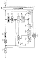
図1は、本発明の第1の実施形態のブロック図であり、ブロック歪み除去前の再構築画像ピクチャに擬似ランダム雑音を混入させて、ブロック歪み除去後の再構築画像ピクチャにウィナーフィルタを適用する映像符号化装置を示すブロック図である。
FIG. 1 is a block diagram of a first embodiment of the present invention, in which pseudo-random noise is mixed in a reconstructed image picture before removing block distortion, and a Wiener filter is applied to the reconstructed image picture after removing block distortion. It is a block diagram which shows the video coding apparatus to perform.
図1に示すように、本実施形態の映像符号化装置は、MBバッファ101、周波数変換部102、量子化部103、エントロピー符号化部104、逆量子化部105、逆周波数変換部106、ピクチャバッファ107、ブロック歪み除去フィルタ部108、デコードピクチャバッファ109、イントラ予測部110、フレーム間予測部111、符号化制御部112およびスイッチ100に加えて、雑音混入器113およびウィナーフィルタ部114を備えている。
As shown in FIG. 1, the video encoding apparatus according to the present embodiment includes an
本実施形態の映像符号化装置は、雑音混入器113とウィナーフィルタ部114が設けられている点と、ピクチャバッファ107に格納された再構築画像ピクチャに対して雑音混入器113から供給される擬似ランダム雑音が混入させられてブロック歪み除去フィルタ部108に供給されている点とが、図21に示された一般的な映像符号化装置と異なっている。よって、以下の説明では、特に、本実施形態の映像符号化装置の特徴である雑音混入器113とウィナーフィルタ部114との動作を詳細に説明をする。
The video encoding apparatus of the present embodiment is provided with a
MBバッファ101には、入力画像フレームの符号化対象MBの画素値が格納される。
The
MBバッファ101から供給される入力MBから、スイッチ100を介してイントラ予測部110またはフレーム間予測部111から供給される予測信号が減じられる。
The prediction signal supplied from the
イントラ予測部110は、ピクチャバッファ107に格納された再構築画像であって現在のフレームと表示時刻が同一である再構築画像を利用してイントラ予測信号を生成する。イントラ予測に関連する情報として、イントラ予測のブロックサイズを示すイントラ予測モード、および方向を示すイントラ予測方向がある。
The
フレーム間予測部111は、現在のフレームと表示時刻が異なる、デコードピクチャバッファ109に格納された参照画像を利用してフレーム間予測信号を生成する。フレーム間予測に関連する情報として、フレーム間予測のブロックサイズを示すフレーム間予測モード、フレーム間予測の方向を示すフレーム間予測方向、デコードピクチャバッファ109に格納された参照ピクチャを同定する参照ピクチャインデックス、フレーム間予測の動きベクトルなどがある。
The
符号化制御部112は、イントラ予測信号およびフレーム間予測信号とMBバッファ101に格納されている入力MBとを比較して、予測誤差画像ブロックのエネルギーが小さくなる予測信号を選択し、スイッチ100を制御する。選択された予測信号に関連する情報は、エントロピー符号化部104に供給される。
The
また、符号化制御部112は、入力MBまたは予測誤差画像ブロックに基づいて、予測誤差画像ブロックの周波数変換に適した整数DCTの基底ブロックサイズを選択する。選択された整数DCTの基底サイズは、周波数変換部102およびエントロピー符号化部104に供給される。通常、入力MBまたは予測誤差画像ブロックの画素値が平坦になる程、より大きな基底ブロックサイズが選択される。換言すると、大きな基底ブロックサイズの再構築画像ブロックでは再構築画像は平坦である。なお、予測誤差画像ブロックのエネルギーが小さくなる予測信号がイントラ予測信号である場合には、選択された整数DCTの基底サイズはイントラ予測モードのブロックサイズと同一である。
Also, the
さらに、符号化制御部112は、目標ビット数以下でフレームを符号化するために、エントロピー符号化部104が出力するビットストリームのビット数を監視する。そして、出力されるビットストリームのビット数が目標ビット数よりも多ければ量子化ステップサイズを大きくする量子化パラメータを出力し、逆に出力されるビットストリームのビット数が目標ビット数よりも少なければ量子化ステップサイズを小さくする量子化パラメータを出力する。そのようにして、出力ビットストリームは目標のビット数に近づくように符号化される。
Further, the
周波数変換部102は、選択された整数DCTの基底サイズで、予測誤差画像ブロックを周波数変換して空間領域から周波数領域に変換する。
The
量子化部103は、変換係数を、符号化制御部112が供給する量子化パラメータに対応する量子化ステップサイズで量子化する。
The
エントロピー符号化部104は、選択された予測信号に関連する情報、整数DCTの基底サイズ、および量子化インデックスをエントロピー符号化して、そのビット列すなわちビットストリームとして出力する。
The
逆量子化部105および逆変換部106は、以後の符号化のために、量子化部103から供給される量子化インデックスを逆量子化し、さらに逆周波数変換して元の空間領域に戻す。すなわち、再構築予測誤差画像ブロックを生成する。
The
ピクチャバッファ107には、現在のフレームに含まれるすべてのMBが符号化されるまで、再構築予測誤差画像ブロックに予測信号が加えられた再構築画像ブロックが格納される。
The
雑音混入器113は、擬似ランダム雑音n(i)を発生する。擬似ランダム雑音n(i)を、例えば、式(1)による線形合同法などに基づいて発生すればよい。
The
n(i)=(a×n(i−1)+b)%c ・・・(1) n (i) = (a × n (i−1) + b)% c (1)
ただし、a,bおよびcは擬似ランダム雑音の周期を決定するパラメータであり、a>0,b>0,a≦c,b<cである、また、x%yは、xをyで割った余りを返す処理を示す。 Where a, b and c are parameters for determining the period of pseudo-random noise, and a> 0, b> 0, a ≦ c, b <c, and x% y is obtained by dividing x by y. Indicates the process of returning the remainder.
なお、本発明では、擬似ランダム雑音の発生方法としてどのような発生方法も使用可能であるが、擬似ランダム雑音の発生器は所定の映像符号化単位または映像復号単位でリセットされることが可能であることが望ましい。図2は、擬似ランダム雑音の発生器を所定の映像符号化単位または映像復号単位でリセットする他の実施形態におけるリセットを説明するための説明図である。所定の映像符号化単位または映像復号単位として、例えば、各フレームの先頭MB(図2(a)参照)、各フレーム内での複数個のMB毎(図2(b)参照)、再構築画像の画素の依存関係を利用したMBの組毎などがある。擬似ランダム雑音の発生器を所定の映像符号化単位または映像復号単位でリセットすることによって、例えば、図2(a)に示された例では映像復号のためのランダムアクセス性を改善でき、図2(b)に示された例では映像符号化および映像復号それぞれの並列処理性を改善できる。 In the present invention, any generation method can be used as a method for generating pseudo-random noise. However, the pseudo-random noise generator can be reset in a predetermined video encoding unit or video decoding unit. It is desirable to be. FIG. 2 is an explanatory diagram for explaining reset in another embodiment in which the pseudo random noise generator is reset in a predetermined video encoding unit or video decoding unit. As a predetermined video coding unit or video decoding unit, for example, the first MB of each frame (see FIG. 2A), a plurality of MBs in each frame (see FIG. 2B), a reconstructed image For example, there are MB pairs using the pixel dependency. By resetting the pseudo random noise generator in a predetermined video encoding unit or video decoding unit, for example, in the example shown in FIG. 2A, random accessibility for video decoding can be improved. In the example shown in (b), the parallel processability of each of video encoding and video decoding can be improved.
例えば、符号化制御部112は、所定の映像符号化単位で、上述した線形合同法に基づく擬似ランダム雑音の発生器における擬似ランダム雑音n(i)の初期値n(0)を所定値でリセットすればよい。また、映像符号化装置は、リセットの所定値または所定値を同定するための情報をビットストリームに埋め込んでもよい。映像復号装置は、ビットストリームに埋め込まれたリセットの所定値または所定値を同定するための情報を読み出し、その情報に基づいて擬似ランダム雑音を発生することによって、映像符号化側と同一の擬似ランダム雑音を発生できるので、映像符号化と映像復号間での擬似ランダム雑音に起因する画像のミスマッチを回避できる。
For example, the
ピクチャバッファ107とブロック歪み除去フィルタ部108の間にある加算器は、再構築画像ピクチャの各位置(i,j){0≦i≦width−1,0≦j≦height−1}の画素rijに、式(2)によって擬似ランダム雑音ni,j(式(1)のn(i)を適当な方法で並び替えたとする)を混入させる。The adder between the
rij=((rij<<6)+(ni,j%64)+32)>>6 ・・・(2)r ij = ((r ij << 6) + (n i, j % 64) +32) >> 6 (2)
ただし、widthとheightは、それぞれフレームの水平解像度、垂直解像度である。 However, width and height are the horizontal resolution and vertical resolution of the frame, respectively.
式(2)に示すように、擬似ランダム雑音の影響強度が絶対値で1画素以下になるように、64で割った余りが加えられている。擬似ランダム雑音の影響強度を絶対値で1画素以下にすることによって、擬似ランダム雑音混入によるPSNR(Peak Signal to Noise Ratio)の低下を抑制できる。
As shown in Equation (2), the remainder divided by 64 is added so that the influence intensity of the pseudo-random noise is 1 pixel or less in absolute value. By making the influence intensity of
ブロック歪み除去フィルタ部108は、雑音が混入された再構築画像ピクチャに対してブロック歪みを除去する。以下、ブロック歪みが除去された再構築画像ピクチャをブロック歪み除去再構築画像ピクチャという。
The block distortion
符号化制御部112は、入力フレーム(入力ピクチャ)とブロック歪み除去再構築画像ピクチャとを利用して、ブロック歪み除去再構築画像ピクチャの平均2乗誤差が最小になるウィナーフィルタを構成する。
The
入力ピクチャをS、ウィナーフィルタ適用前のブロック歪み除去再構築画像ピクチャをX、ウィナーフィルタ適用後のブロック歪み除去再構築画像ピクチャをX’とすると、平均2乗誤差E[e2]は式(3)で定義される。Assuming that the input picture is S, the block distortion-reconstructed reconstructed image picture before applying the Wiener filter is X, and the block distortion-reconstructed reconstructed image picture after applying the Wiener filter is X ′, the mean square error E [e 2 ] is Defined in 3).

ただし、*は畳み込み演算、h(τ){0≦τ≦n−1}はウィナーフィルタのフィルタ係数、RXXはXの自己相関係数、RSXはSとXの相互相関係数である。式(3)を各フィルタ係数について偏微分し、左辺をゼロとすると、以下の式(4)の関係式(Wiener-hops equations )が得られる。Where * is a convolution operation, h (τ) {0 ≦ τ ≦ n−1} is a filter coefficient of a Wiener filter, R XX is an autocorrelation coefficient of X, and R SX is a cross correlation coefficient of S and X. . When the equation (3) is partially differentiated with respect to each filter coefficient and the left side is zero, the following relational equation (Wiener-hops equations) of the equation (4) is obtained.
左辺の列ベクトルをY、右辺の行列および列ベクトルをそれぞれAおよびXとすると、Y=AXとなり、ガウスの消去法を適用することによって、ウィナーフィルタのフィルタ係数h(τ)を計算できる。すなわち、ウィナーフィルタを構成することができる。 If the column vector on the left side is Y, and the matrix and column vector on the right side are A and X, respectively, Y = AX, and the filter coefficient h (τ) of the Wiener filter can be calculated by applying the Gaussian elimination method. That is, a Wiener filter can be configured.
符号化制御部112が計算したウィナーフィルタhは、ウィナーフィルタ部114とエントロピー符号化部104とに供給される。エントロピー符号化部104は、供給されたウィナーフィルタhのフィルタ係数をビットストリームに多重化する。
The winner filter h calculated by the
ウィナーフィルタ部114は、計算したウィナーフィルタhをブロック歪み除去再構築画像ピクチャXに適用する。定式的には、式(5)のようになる。
The
X’=X*h ・・・(5) X '= X * h (5)
デコードピクチャバッファ109は、ウィナーフィルタを適用後のブロック歪み除去画像ピクチャX’を参照画像ピクチャとして格納する。なお、参照画像ピクチャの画像は、フレーム間予測信号を生成するための参照画像として利用される。 The decoded picture buffer 109 stores the block distortion-removed image picture X ′ after applying the Wiener filter as a reference image picture. The image of the reference image picture is used as a reference image for generating an inter-frame prediction signal.
本実施形態の映像符号化装置は、上記のような処理によってビットストリームを生成する。 The video encoding apparatus according to the present embodiment generates a bit stream by the process as described above.
本実施形態の映像符号化装置は、ブロック歪み除去前の再構築画像ピクチャに擬似ランダム雑音を混入させて、ブロック歪み除去後の再構築画像ピクチャにウィナーフィルタを適用する。擬似ランダム雑音の混入によって、特に平坦領域において、ブロック歪み除去フィルタ部に階段アーティファクトの低減効果を与えることができる。また、特に平坦領域において、ウィナーフィルタに輪郭アーティファクトの低減効果を与えることができる。すなわち、本実施形態の映像符号化装置では、輪郭および階段アーティファクトを効率的に低減するために、擬似ランダム雑音混入とウィナーフィルタとが好適に組み合わせられている。さらに、擬似ランダム雑音の影響強度を絶対値で1画素以下になる擬似ランダム雑音を利用することによって、擬似ランダム雑音混入によるPSNRの低下とフレーム間差分の発生に起因する圧縮効率の低下の双方を抑制できる。 The video encoding apparatus according to the present embodiment mixes pseudo-random noise in a reconstructed image picture before removing block distortion, and applies a Wiener filter to the reconstructed image picture after removing block distortion. By mixing pseudo-random noise, it is possible to give a step artifact reduction effect to the block distortion removal filter unit, particularly in a flat region. Further, the contour artifact can be reduced in the Wiener filter, particularly in a flat region. That is, in the video encoding apparatus of the present embodiment, the pseudo-random noise mixture and the Wiener filter are suitably combined in order to efficiently reduce the contour and staircase artifacts. Furthermore, by using pseudo-random noise whose pseudo-random noise influence intensity is 1 pixel or less in absolute value, both the reduction in PSNR due to the inclusion of pseudo-random noise and the reduction in compression efficiency due to the generation of inter-frame differences are achieved. Can be suppressed.
実施形態2.
図3は、本発明の第2の実施形態のブロック図であり、ブロック歪み除去後の再構築画像ピクチャに擬似ランダム雑音を混入させ、さらにウィナーフィルタを適用する映像符号化装置を示すブロック図である。
FIG. 3 is a block diagram of a second embodiment of the present invention, which is a block diagram showing a video encoding apparatus that applies pseudo-random noise to a reconstructed image picture after removal of block distortion and further applies a Wiener filter. is there.
図3に示すように、本実施形態の映像符号化装置は、MBバッファ101、周波数変換部102、量子化部103、エントロピー符号化部104、逆量子化部105、逆周波数変換部106、ピクチャバッファ107、ブロック歪み除去フィルタ部108、デコードピクチャバッファ109、イントラ予測部110、フレーム間予測部111、符号化制御部112およびスイッチ100に加えて、雑音混入器113およびウィナーフィルタ部114を備えている。
As shown in FIG. 3, the video encoding apparatus according to the present embodiment includes an
本実施形態の映像符号化装置を図1に示された第1実施形態の映像符号化装置とは異なり、ブロック歪み除去フィルタ部108によってブロック歪みが除去された再構築画像ピクチャが、雑音混入器113から供給される擬似ランダム雑音が混入させられた後にウィナーフィルタ部114に供給されている。
Unlike the video encoding apparatus of the first embodiment shown in FIG. 1, the reconstructed image picture from which block distortion has been removed by the block distortion removing
MBバッファ101は、入力画像フレームの符号化対象MBの画素値を格納する。
The
MBバッファ101から供給される入力MBから、スイッチ100を介してイントラ予測部110またはフレーム間予測部111から供給される予測信号が減じられる。
The prediction signal supplied from the
イントラ予測部110は、ピクチャバッファ107に格納された再構築画像であって現在のフレームと表示時刻が同一である再構築画像を利用してイントラ予測信号を生成する。イントラ予測に関連する情報として、イントラ予測のブロックサイズを示すイントラ予測モード、および方向を示すイントラ予測方向がある。
The
フレーム間予測部111は、現在のフレームと表示時刻が異なる、デコードピクチャバッファ109に格納された参照画像を利用してフレーム間予測信号を生成する。フレーム間予測に関連する情報として、フレーム間予測のブロックサイズを示すフレーム間予測モード、フレーム間予測の方向を示すフレーム間予測方向、デコードピクチャバッファ109に格納された参照ピクチャを同定する参照ピクチャインデックス、フレーム間予測の動きベクトルなどがある。
The
符号化制御部112は、イントラ予測信号およびフレーム間予測信号とMBバッファ101に格納されている入力MBとを比較して、予測誤差画像ブロックのエネルギーが小さくなる予測信号を選択し、スイッチ100を制御する。選択された予測信号に関連する情報は、エントロピー符号化部104に供給される。
The
また、符号化制御部112は、入力MBまたは予測誤差画像ブロックに基づいて、予測誤差画像ブロックの周波数変換に適した整数DCTの基底ブロックサイズを選択する。選択された整数DCTの基底サイズは、周波数変換部102およびエントロピー符号化部104に供給される。通常、入力MBまたは予測誤差画像ブロックの画素値が平坦になる程、より大きな基底ブロックサイズが選択される。換言すると、大きな基底ブロックサイズの再構築画像ブロックでは再構築画像は平坦である。なお、予測誤差画像ブロックのエネルギーが小さくなる予測信号がイントラ予測信号である場合には、選択された整数DCTの基底サイズはイントラ予測モードのブロックサイズと同一である。
Also, the
さらに、符号化制御部112は、目標ビット数以下でフレームを符号化するために、エントロピー符号化部104が出力するビットストリームのビット数を監視する。そして、出力されるビットストリームのビット数が目標ビット数よりも多ければ量子化ステップサイズを大きくする量子化パラメータを出力し、逆に出力されるビットストリームのビット数が目標ビット数よりも少なければ量子化ステップサイズを小さくする量子化パラメータを出力する。そのようにして、出力ビットストリームは目標のビット数に近づくように符号化される。
Further, the
周波数変換部102は、選択された整数DCTの基底サイズにて、予測誤差画像ブロックを周波数変換して空間領域から周波数領域に変換する。
The
量子化部103は、変換係数を、符号化制御部112が供給する量子化パラメータに対応する量子化ステップサイズで量子化する。
The
エントロピー符号化部104は、選択された予測信号に関連する情報、整数DCTの基底サイズ、および量子化インデックスをエントロピー符号化して、そのビット列すなわちビットストリームとして出力する。
The
逆量子化部105および逆変換部106は、以後の符号化のために、量子化部103から供給される量子化インデックスを逆量子化し、さらに逆周波数変換して元の空間領域に戻す。すなわち、再構築予測誤差画像ブロックを生成する。
The
ピクチャバッファ107には、現在のフレームに含まれるすべてのMBが符号化されるまで、再構築予測誤差画像ブロックに予測信号が加えられた再構築画像ブロックが格納される。
The
ブロック歪み除去フィルタ部108は、ピクチャバッファ107に格納された再構築画像ピクチャに対してブロック歪みを除去する。すなわち、ブロック歪み除去再構築画像ピクチャを生成する。
The block distortion
雑音混入器113は、第1実施形態の場合と同様に、擬似ランダム雑音n(i)を発生する。
The
ブロック歪み除去フィルタ部108とウィナーフィルタ部114との間にある加算器は、第1実施形態の場合と同様に、再構築画像ピクチャの各位置(i,j){0≦i≦width−1,0≦j≦height−1}の画素xijに、式(6)によって擬似ランダム雑音ni,j(式(1)のn(i)を適当な方法で並び替えたとする)を混入させる。As in the case of the first embodiment, the adder between the block distortion removing
xij=((xij<<6)+(ni,j%64)+32)>>6 ・・・(6)x ij = ((x ij << 6) + (n i, j % 64) +32) >> 6 (6)
符号化制御部112は、第1実施形態の場合と同様に、入力フレーム(入力ピクチャ)と擬似ランダム雑音を混入させたブロック歪み除去再構築画像ピクチャとを利用して、ブロック歪みが除去された再構築画像ピクチャの平均2乗誤差が最小となるウィナーフィルタhを計算する。
As in the case of the first embodiment, the
符号化制御部112が計算したウィナーフィルタhは、ウィナーフィルタ部114とエントロピー符号化部104とに供給される。エントロピー符号化部104は、供給されたウィナーフィルタhのフィルタ係数をビットストリームに多重化する。
The winner filter h calculated by the
ウィナーフィルタ部114は、第1実施形態の場合と同様に、計算したウィナーフィルタhをブロック歪みが除去されたブロック歪み除去再構築画像ピクチャXに適用する。定式的には、式(7)のようになる。
As in the case of the first embodiment, the
X’=X*h ・・・(7) X '= X * h (7)
デコードピクチャバッファ109は、ウィナーフィルタを適用後のブロック歪み除去画像ピクチャX’を参照画像ピクチャとして格納する。なお、参照画像ピクチャの画像は、フレーム間予測信号を生成するための参照画像として利用される。 The decoded picture buffer 109 stores the block distortion-removed image picture X ′ after applying the Wiener filter as a reference image picture. The image of the reference image picture is used as a reference image for generating an inter-frame prediction signal.
本実施形態の映像符号化装置は、上記のような処理によってビットストリームを生成する。 The video encoding apparatus according to the present embodiment generates a bit stream by the process as described above.
本実施形態の映像符号化装置は、ブロック歪み除去後の再構築画像ピクチャに擬似ランダム雑音を混入させて、ブロック歪み除去後の再構築画像ピクチャにウィナーフィルタを適用する。擬似ランダム雑音の混入によって、特に平坦領域において、ブロック歪み除去フィルタ部に階段アーティファクトの低減効果を与えることができる。また、特に平坦領域において、ウィナーフィルタに輪郭アーティファクトの低減効果を与えることができる。すなわち、本実施形態の映像符号化装置では、輪郭および階段アーティファクトを効率的に低減するために、擬似ランダム雑音混入とウィナーフィルタとが好適に組み合わせられている。さらに、擬似ランダム雑音の影響強度を絶対値で1画素以下になる擬似ランダム雑音を利用することによって、擬似ランダム雑音混入によるPSNRの低下とフレーム間差分の発生に起因する圧縮効率の低下の双方を抑制できる。 The video encoding apparatus according to the present embodiment mixes pseudo-random noise in a reconstructed image picture after removal of block distortion, and applies a Wiener filter to the reconstructed image picture after removal of block distortion. By mixing pseudo-random noise, it is possible to give a step artifact reduction effect to the block distortion removal filter unit, particularly in a flat region. Further, the contour artifact can be reduced in the Wiener filter, particularly in a flat region. That is, in the video encoding apparatus of the present embodiment, the pseudo-random noise mixture and the Wiener filter are suitably combined in order to efficiently reduce the contour and staircase artifacts. Furthermore, by using pseudo-random noise whose pseudo-random noise influence intensity is 1 pixel or less in absolute value, both the reduction in PSNR due to the inclusion of pseudo-random noise and the reduction in compression efficiency due to the generation of inter-frame differences Can be suppressed.
実施形態3.
図4は、本発明の第3の実施形態のブロック図であり、ブロック歪み除去後の再構築画像ピクチャに擬似ランダム雑音を混入させてウィナーフィルタを適用する映像復号装置を示すブロック図である。なお、本実施形態の映像復号装置は、第1の実施形態の映像符号化装置に対応する映像復号装置である。
FIG. 4 is a block diagram of a third embodiment of the present invention, and is a block diagram showing a video decoding apparatus that applies a Wiener filter by mixing pseudo-random noise into a reconstructed image picture after removal of block distortion. Note that the video decoding apparatus according to the present embodiment is a video decoding apparatus corresponding to the video encoding apparatus according to the first embodiment.
図4に示すように、本実施形態の映像復号装置は、エントロピー復号部201、逆量子化部202、逆周波数変換部203、ピクチャバッファ204、ブロック歪み除去フィルタ部205、デコードピクチャバッファ206、イントラ予測部207、フレーム間予測部208、復号制御部209およびスイッチ200に加えて、雑音混入器210、ウィナーフィルタ211を備えている。
As shown in FIG. 4, the video decoding apparatus according to the present embodiment includes an
エントロピー復号部201は、ビットストリームをエントロピー復号して、復号対象MBの予測信号に関連する情報、整数DCTの基底サイズ、量子化インデックスを、逆量子化部202および復号制御部209に供給する。また、ビットストリームに多重化されたフィルタ係数も復号制御部209に供給する。
The
イントラ予測部207は、イントラMBに対して、現在復号中のフレームと表示時刻が同一である、ピクチャバッファ204に格納された再構築画像から、復号制御部209を介して供給されるエントロピー復号したイントラ予測モードとイントラ予測方向とに基づいて、イントラ予測信号を生成して、スイッチ200に供給する。
The
フレーム間予測部208は、インターMBに対して、現在復号中のフレームと表示時刻が異なる、デコードピクチャバッファ206に格納された参照画像から、復号制御部209を介して供給されるエントロピー復号したフレーム間予測モード、フレーム間予測方向、および動きベクトルに基づいて、フレーム間予測信号を生成して、スイッチ200に供給する。
The
復号制御部209は、エントロピー復号した予測信号に関連する情報(イントラMBまたはインターMB)に基づいて、スイッチ200を制御し、イントラ予測信号またはフレーム間予測信号を予測信号として出力させる。また、エントロピー復号部201から供給されたフィルタ係数をウィナーフィルタ部211に供給する。
The
逆量子化部202および逆変換部203は、以後の符号化のために、エントロピー復号部201から供給される量子化インデックスを逆量子化し、さらに逆周波数変換して元の空間領域に戻す。すなわち、再構築予測誤差画像ブロックを生成する。
The
ピクチャバッファ204には、現在のフレームに含まれるすべてのMBが符号化されるまで、再構築予測誤差画像ブロックに予測信号が加えられた再構築画像ブロックが格納される。
The
雑音混入器113は、第1実施形態の場合と同様に、擬似ランダム雑音n(i)を発生する。
The
ピクチャバッファ204とブロック歪み除去フィルタ部205の間にある加算器は、第1実施形態の場合と同様に、再構築画像ピクチャに擬似ランダム雑音を混入させる。
The adder located between the
ブロック歪み除去フィルタ部205は、雑音が混入された再構築画像ピクチャに対してブロック歪みを除去する。すなわち、ブロック歪み除去再構築画像ピクチャを生成する。
The block distortion
ウィナーフィルタ211は、第1実施形態の場合と同様に、復号制御部209から供給されるウィナーフィルタhをブロック歪みが除去された再構築画像ピクチャに適用する。
Similarly to the case of the first embodiment, the
デコードピクチャバッファ206には、ウィナーフィルタを適用後のブロック歪み除去画像ピクチャを参照画像ピクチャとして格納する。また、参照画像ピクチャは、適切な表示タイミングで伸張フレームとして出力される。 The decoded picture buffer 206 stores the block distortion-removed image picture after applying the Wiener filter as a reference image picture. Further, the reference image picture is output as an expanded frame at an appropriate display timing.
本実施形態の映像復号装置は、上記のような処理によってビットストリームを伸張する。 The video decoding apparatus according to the present embodiment decompresses the bit stream by the processing as described above.
本実施形態の映像復号装置は、ブロック歪み除去前の再構築画像ピクチャに擬似ランダム雑音を混入させて、ブロック歪み除去後の再構築画像ピクチャにウィナーフィルタを適用する。擬似ランダム雑音の混入によって、特に平坦領域において、ブロック歪み除去フィルタ部に階段アーティファクトの低減効果を与えることができる。また、特に平坦領域において、ウィナーフィルタに輪郭アーティファクトの低減効果を与えることができる。この結果、伸張フレームにおける階段および輪郭アーティファクトを効果的に低減できる。 The video decoding apparatus according to the present embodiment mixes pseudo-random noise in a reconstructed image picture before removing block distortion, and applies a Wiener filter to the reconstructed image picture after removing block distortion. By mixing pseudo-random noise, it is possible to give a step artifact reduction effect to the block distortion removal filter unit, particularly in a flat region. Further, the contour artifact can be reduced in the Wiener filter, particularly in a flat region. As a result, staircase and contour artifacts in the extension frame can be effectively reduced.
実施形態4.
図5は、本発明の第4の実施形態のブロック図であり、ブロック歪み除去前の再構築画像ピクチャに擬似ランダム雑音を混入させて、ブロック歪み除去後の再構築画像ピクチャにウィナーフィルタを適用する映像復号装置を示すブロック図である。また、本実施形態の映像復号装置は、第2の実施形態の映像符号化装置に対応する映像復号装置である。
FIG. 5 is a block diagram of the fourth embodiment of the present invention, in which pseudo-random noise is mixed in a reconstructed image picture before removing block distortion, and a Wiener filter is applied to the reconstructed image picture after removing block distortion. It is a block diagram which shows the video decoding apparatus to perform. The video decoding apparatus according to the present embodiment is a video decoding apparatus corresponding to the video encoding apparatus according to the second embodiment.
図5に示すように、本実施形態の映像復号装置は、エントロピー復号部201、逆量子化部202、逆周波数変換部203、ピクチャバッファ204、ブロック歪み除去フィルタ部205、デコードピクチャバッファ206、イントラ予測部207、フレーム間予測部208、復号制御部209およびスイッチ200に加えて、雑音混入器210、ウィナーフィルタ211を備えている。
As shown in FIG. 5, the video decoding apparatus according to the present embodiment includes an
本実施形態の映像復号装置は、図4に示された第3の実施形態の映像復号装置とは異なり、ブロック歪み除去フィルタ部205でブロック歪みが除去された再構築画像ピクチャが雑音混入器210から供給される擬似ランダム雑音が混入させられてウィナーフィルタ211に供給される。
Unlike the video decoding apparatus according to the third embodiment illustrated in FIG. 4, the video decoding apparatus according to the present embodiment includes a reconstructed image picture from which block distortion has been removed by the block distortion
エントロピー復号部201は、ビットストリームをエントロピー復号して、復号対象MBの予測信号に関連する情報、整数DCTの基底サイズおよび量子化インデックスを、逆量子化部202および復号制御部209に供給する。また、ビットストリームに多重化されたフィルタ係数も復号制御部209に供給する。
The
イントラ予測部207は、イントラMBに対して、現在復号中のフレームと表示時刻が同一である、ピクチャバッファ204に格納された再構築画像から、復号制御部209を介して供給されるエントロピー復号したイントラ予測モードとイントラ予測方向とに基づいて、イントラ予測信号を生成して、スイッチ200に供給する。
The
フレーム間予測部208は、インターMBに対して、現在復号中のフレームと表示時刻が異なる、デコードピクチャバッファ206に格納された参照画像から、復号制御部209を経由して供給されるエントロピー復号したフレーム間予測モード、フレーム間予測方向および動きベクトルに基づいて、フレーム間予測信号を生成して、スイッチ200に供給する。
The
復号制御部209は、エントロピー復号した予測信号に関連する情報(イントラMBまたはインターMB)に基づいて、スイッチ200を制御し、イントラ予測信号またはフレーム間予測信号を予測信号として供給させる。また、エントロピー復号部201からのフィルタ係数をウィナーフィルタ部211に供給する。
The
逆量子化部202および逆変換部203は、以後の符号化のために、エントロピー復号部201から供給される量子化インデックスを逆量子化し、さらに逆周波数変換して元の空間領域に戻す。すなわち、再構築予測誤差画像ブロックを生成する。
The
ピクチャバッファ204には、現在のフレームに含まれるすべてのMBが復号されるまで、再構築予測誤差画像ブロックに予測信号が加えられた再構築画像ブロックが格納される。
The
雑音混入器113は、第1実施形態の場合と同様に、擬似ランダム雑音n(i)を発生する。
The
ピクチャバッファ204とブロック歪み除去フィルタ部205の間にある加算器は、第1実施形態の場合と同様に、再構築画像ピクチャに擬似ランダム雑音を混入させる。
The adder located between the
ブロック歪み除去フィルタ部205は、雑音が混入された再構築画像ピクチャに対してブロック歪みを除去する。すなわち、ブロック歪み除去再構築画像ピクチャを生成する。
The block distortion
ウィナーフィルタ211は、第1実施形態の場合と同様に、復号制御部209から供給されるウィナーフィルタhをブロック歪みが除去された再構築画像ピクチャに適用する。
Similarly to the case of the first embodiment, the
デコードピクチャバッファ206は、ウィナーフィルタを適用後のブロック歪み除去画像ピクチャを参照画像ピクチャとして格納する。また、参照画像ピクチャは、適切な表示タイミングで伸張フレームとして出力される。 The decoded picture buffer 206 stores the block distortion-removed image picture after applying the Wiener filter as a reference image picture. Further, the reference image picture is output as an expanded frame at an appropriate display timing.
本実施形態の映像復号装置は、上記のような処理によってビットストリームを伸張する。 The video decoding apparatus according to the present embodiment decompresses the bit stream by the processing as described above.
本実施形態の映像復号装置は、ブロック歪み除去後の再構築画像ピクチャに擬似ランダム雑音を混入させて、ブロック歪み除去後の再構築画像ピクチャにウィナーフィルタを適用する。擬似ランダム雑音の混入によって、特に平坦領域において、ウィナーフィルタに輪郭アーティファクトの低減効果を与えることができる。この結果、伸張フレームにおける階段および輪郭アーティファクトを効果的に低減できる。 The video decoding apparatus according to the present embodiment mixes pseudo-random noise in a reconstructed image picture after removal of block distortion, and applies a Wiener filter to the reconstructed image picture after removal of block distortion. The inclusion of pseudo-random noise can give an effect of reducing contour artifacts to the Wiener filter, particularly in a flat region. As a result, staircase and contour artifacts in the extension frame can be effectively reduced.
次に、他の実施形態を説明する。他の実施形態として、画素値の変動量を利用する実施形態が考えられる。 Next, another embodiment will be described. As another embodiment, an embodiment using a fluctuation amount of a pixel value is conceivable.
輪郭および階段アーティファクトは、画素値の変動量が小さい平坦な画像領域で顕著になる傾向がある。この傾向に着目し、上述した雑音混入器が、再構築画像の画素値の変動量を計算し、計算した画素値の変動量の大小に基づいて擬似ランダム雑音混入位置を決定する実施形態も考えられる。画素値の変動量を利用することによって、適切な量の擬似ランダム雑音を混入させて、輪郭および階段アーティファクトに対する人間の視覚感度をより低減できる。 Contours and staircase artifacts tend to be noticeable in flat image areas where the amount of pixel value variation is small. Focusing on this tendency, an embodiment is also considered in which the above-mentioned noise mixer calculates the fluctuation amount of the pixel value of the reconstructed image and determines the pseudo random noise mixing position based on the magnitude of the calculated fluctuation amount of the pixel value. It is done. By utilizing the amount of variation of the pixel value, an appropriate amount of pseudo-random noise can be mixed to further reduce human visual sensitivity to contour and staircase artifacts.
例えば、雑音混入器が、再構築画像ピクチャの各位置(i,j){0≦i≦width−1,0≦j≦height−1}の画素xijについて、式(8)によって周辺画素値(xi+m,j+n{−w≦m≦w,−h≦n≦h}の変動量pVi,jを計算する。For example, the noise mixer uses the expression (8) to calculate the peripheral pixel value for the pixel x ij at each position (i, j) {0 ≦ i ≦ width−1, 0 ≦ j ≦ height−1} of the reconstructed image picture. The variation amount pV i, j of (x i + m, j + n {−w ≦ m ≦ w, −h ≦ n ≦ h}) is calculated.
そして、例えば式(9)に基づいて、所定のしきい値thよりもpVi,jが小さい位置の画素xijのみに擬似ランダム雑音ni,jを混入させる。Then, for example, based on the equation (9), the pseudo random noise n i, j is mixed only in the pixel x ij at a position where pV i, j is smaller than the predetermined threshold th.
第1から第4の実施形態の映像符号化装置および映像復号装置に対して、画素値の変動量の大小に基づいて擬似ランダム雑音混入位置を決定する雑音混入器を適用した場合には、映像符号化装置の構成は図6または図7に示すようになり、映像復号装置の構成は図8または図9に示すようになる。 When a noise mixer that determines a pseudo-random noise mixing position based on the amount of variation in pixel value is applied to the video encoding device and the video decoding device of the first to fourth embodiments, The configuration of the encoding device is as shown in FIG. 6 or FIG. 7, and the configuration of the video decoding device is as shown in FIG. 8 or FIG.
すなわち、図6および図7に示すように、映像符号化装置において、雑音混入器113は、ピクチャバッファ107に格納されている参照画像ピクチャ(ブロック歪み除去画像ピクチャ)を入力し、再構築画像の画素値の変動量を計算する。また、図8および図9に示すように、映像復号装置において、雑音混入器210は、ピクチャバッファ204に格納されている参照画像ピクチャ(ブロック歪み除去画像ピクチャ)を入力し、再構築画像の画素値の変動量を計算する。
That is, as shown in FIGS. 6 and 7, in the video encoding device, the
図6および図7に示す映像符号化装置は、ブロック歪み除去前の再構築画像の画素値の変動量を利用しているのに対して、図8および図9に示す映像符号化装置および映像復号装置は、ブロック歪み除去後の再構築画像の画素値の変動量を利用する。ただし、図8および図9に示す映像符号化装置および映像復号装置は、ブロック歪み除去前の再構築画像の画素値の変動量を利用することもできるが、ブロック歪の影響を受けた画素値の変動量となる。 The video encoding device shown in FIGS. 6 and 7 uses the fluctuation amount of the pixel value of the reconstructed image before removing the block distortion, whereas the video encoding device and the video shown in FIGS. 8 and 9 are used. The decoding device uses the amount of change in the pixel value of the reconstructed image after removal of block distortion. However, although the video encoding device and the video decoding device shown in FIGS. 8 and 9 can use the variation amount of the pixel value of the reconstructed image before the block distortion removal, the pixel value affected by the block distortion The amount of fluctuation.
なお、式(8)で示される画素値の変動量の代わりに、周辺画素値の分散、周辺画素値の最大画素値と最小画素値の差分など、平坦な画像領域を検出するための画像メトリックを利用してもよい。 It should be noted that an image metric for detecting a flat image area, such as the variance of the peripheral pixel values and the difference between the maximum pixel value and the minimum pixel value of the peripheral pixel values, instead of the fluctuation amount of the pixel value represented by Expression (8). May be used.
また、他の実施形態として、伸張情報を用いる実施形態が考えられる。 As another embodiment, an embodiment using decompression information is conceivable.
上述した雑音混入器が、再構築画像の画素値の変動量を計算し、計算した画素値の変動量の大小に基づいて擬似ランダム雑音混入位置を決定する実施形態では、変動量の計算量に伴う映像符号化および映像復号の計算効率が低下するおそれがある。 In the embodiment in which the above-described noise mixer calculates the fluctuation amount of the pixel value of the reconstructed image and determines the pseudo random noise mixing position based on the magnitude of the calculated fluctuation amount of the pixel value, the calculation amount of the fluctuation amount is increased. The calculation efficiency of the accompanying video encoding and video decoding may be reduced.
再構築画像ブロックに関連した伸張情報からブロック内やブロック境界における再構築画像の画素値の変動量を推定し、推定した画素値の変動量の大小に基づいて擬似ランダム雑音混入位置または擬似ランダム雑音混入候補位置を決定する実施形態も考えられる。ただし、擬似ランダム雑音混入候補位置を、上述した計算された再構築画像の画素値の変動量に基づいて擬似ランダム雑音混入位置として決定される画素位置とする。 Estimates the amount of fluctuation of the pixel value of the reconstructed image in the block or at the block boundary from the decompression information related to the reconstructed image block. An embodiment for determining the mixing candidate position is also conceivable. However, the pseudo-random noise mixing candidate position is a pixel position determined as the pseudo-random noise mixing position based on the calculated amount of change in the pixel value of the reconstructed image described above.
例えば、雑音混入器が、再構築画像ピクチャの画像に関連した伸張情報として、予測信号に関連する情報、整数DCTの基底サイズに関する情報、有意な交流(Alternate Current (AC))の量子化インデックスを利用して、変動量を推定する。そのように構成されることによって、再構築画像のすべての画素値を比較して画素値の変動量を計算することなく、輪郭および階段アーティファクトを効率的に低減できる。 For example, as a decompression information related to the image of the reconstructed image picture, a noise mixer uses information related to the prediction signal, information about the base size of the integer DCT, and a significant alternating current (AC) quantization index. Use this to estimate the amount of variation. With such a configuration, it is possible to efficiently reduce contours and staircase artifacts without comparing all pixel values of the reconstructed image and calculating the amount of pixel value variation.
第1から第4の実施形態の映像符号化装置および映像復号装置に対して、変動量を推定する雑音混入器を適用した場合には、映像符号化装置の構成は図10または図11に示すようになり、映像復号装置の構成は図12または図13に示すようになる。 When a noise mixer that estimates the amount of variation is applied to the video encoding device and the video decoding device of the first to fourth embodiments, the configuration of the video encoding device is shown in FIG. 10 or FIG. Thus, the configuration of the video decoding apparatus is as shown in FIG.
すなわち、図10および図11に示すように、映像符号化装置において、雑音混入器113は、ピクチャバッファ107に格納されている参照画像ピクチャ(ブロック歪み除去画像ピクチャ)を入力するとともに、エントロピー符号化部104に入力される選択された予測信号に関連する情報、整数DCTの基底サイズ、および量子化インデックスを入力し、再構築画像の画素値の変動量を推定する。また、図12および図13に示すように、映像復号装置において、雑音混入器210は、ピクチャバッファ204に格納されている参照画像ピクチャ(ブロック歪み除去画像ピクチャ)を入力するとともに、エントロピー復号部201から出力されるビットストリームをエントロピー復号して、復号対象MBの予測信号に関連する情報、整数DCTの基底サイズ、量子化インデックスを入力し、再構築画像の画素値の変動量を推定する。
That is, as shown in FIGS. 10 and 11, in the video encoding device, the
それらの映像符号化装置および映像復号装置は、平坦な予測信号となる予測の種類、大きな整数DCTの基底サイズ、有意なACの量子化インデックスが少ないパターンのいずれかを満たす再構築画像を画素値の変動量が小さいと推定し、推定結果に基づいて擬似ランダム雑音混入位置または擬似ランダム雑音混入候補位置を決定できる。 The video encoding device and the video decoding device have a pixel value of a reconstructed image satisfying any one of a prediction type to be a flat prediction signal, a base size of a large integer DCT, and a pattern with a small significant AC quantization index. It is possible to estimate that the fluctuation amount is small and to determine the pseudo random noise mixed position or the pseudo random noise mixed candidate position based on the estimation result.
なお、平坦な予測信号となる予測の種類として、DC(図14および図15(b)の「2」参照)、水平(図14と図15(b)の「1」参照)、および垂直(図14および図15(b)の「0」参照)のイントラ予測がある。 Note that the types of prediction to be a flat prediction signal are DC (see “2” in FIGS. 14 and 15B), horizontal (see “1” in FIGS. 14 and 15B), and vertical (see “1” in FIGS. 14 and 15B). 14 and FIG. 15B (see “0”).
DC、水平および垂直の方向のイントラ予測の再構築画像を画素値の変動量が小さいと推定する根拠は、非特許文献6に記載されているように、DC、水平および垂直それぞれのイントラ予測方向の予測信号のアダマール変換については、有意な変換係数は特定の成分のみにしか発生しないことに基づいている。具体的には、DCのイントラ予測方向についてはDCのみの有意な変換係数、水平のイントラ予測方向についてはDCおよび垂直成分のACのみの有意な変換係数、垂直のイントラ予測方向についてはDCおよび水平成分のACのみの有意な変換係数になる。
The basis for estimating the reconstructed image of intra prediction in the DC, horizontal and vertical directions that the amount of variation in the pixel value is small is described in
有意な変換係数が特定の成分のみにしか発生しないことは、DCのイントラ予測方向については画像の変動量がゼロ(すなわち、平坦な予測信号)、水平のイントラ予測方向については水平方向の画像の変動量がゼロ(すなわち、水平方向に平坦な予測信号)、垂直のイントラ予測方向については垂直方向の画像の変動量がゼロ(すなわち、垂直方向に平坦な予測信号)であることを示している。 The fact that a significant transform coefficient occurs only in a specific component is that the amount of fluctuation of the image is zero (that is, a flat prediction signal) in the DC intra prediction direction, and the horizontal direction of the image is horizontal. The fluctuation amount is zero (that is, the prediction signal flat in the horizontal direction), and the vertical intra prediction direction indicates that the fluctuation amount of the image in the vertical direction is zero (that is, the prediction signal flat in the vertical direction). .
有意な変換係数が特定の成分のみにしか発生しないことと平坦な予測信号との関連は、アダマール変換だけでなく整数DCTについても成立するため、DC、水平および垂直のイントラ予測に基づく再構築画像を画素値の変動量が小さいと推定できる。 Since the relationship between the fact that a significant transform coefficient occurs only in a specific component and the flat prediction signal holds not only for the Hadamard transform but also for the integer DCT, a reconstructed image based on DC, horizontal and vertical intra prediction Can be estimated that the fluctuation amount of the pixel value is small.
また、大きな整数DCTの基底サイズに基づく再構築画像を画素値の変動量が小さいと推定する根拠は、入力MBが平坦な程、すなわち、変動量が小さい程、より大きなブロックサイズが選択されることに基づいている。 Further, the basis for estimating that a reconstructed image based on the base size of a large integer DCT has a small amount of variation in pixel value is that the larger the input MB is, that is, the smaller the amount of variation, the larger the block size is selected. Is based on that.
有意なACの量子化インデックスが少ないパターンの再構築画像を画素値の変動量が小さいと推定する根拠は、整数DCTのACが画像の変動量に対応していることに基づいている。なお、高周波数成分のACが低周波数成分のACよりも大きな変動量になるので、有意な高周波数成分のAC量子化インデックスが少ないパターンの再構築画像を画素値の変動量が小さいと推定してもよい(なお、前記有意なACの量子化インデックスが少ないパターンには、あらかじめ定められた低周波数成分だけに有意なACの量子化インデックスが存在するパターン、または、すべての周波数成分にわたって有意なACの量子化インデックスが疎に存在するパターンが利用できる。)。 The reason for estimating that a reconstructed image having a pattern with a small significant AC quantization index has a small fluctuation amount of the pixel value is based on the fact that the AC of the integer DCT corresponds to the fluctuation amount of the image. Since the high frequency component AC has a larger fluctuation amount than the low frequency component AC, it is estimated that the reconstructed image of the pattern with a small significant high frequency component AC quantization index has a small pixel value fluctuation amount. (The pattern having a small significant AC quantization index may be a pattern in which a significant AC quantization index exists only in a predetermined low frequency component, or significant across all frequency components. A pattern in which AC quantization indexes exist sparsely can be used.)
以上のことから明らかなように、平坦な予測信号となる予測の種類、大きな整数DCTの基底サイズ、有意なACの量子化インデックスが少ないパターンのいずれかの組み合わせ、または、全てに基づいて、再構築画像の画素値の変動量を推定し、擬似ランダム雑音混入位置または擬似ランダム雑音混入候補位置を決定することもできる。 As is clear from the above, based on any combination or all of the types of prediction that result in a flat prediction signal, the base size of a large integer DCT, and the pattern with a small significant AC quantization index, it is possible It is also possible to estimate the fluctuation amount of the pixel value of the constructed image and determine the pseudo random noise mixed position or the pseudo random noise mixed candidate position.
さらに、雑音混入器が、再構築画像ブロックの伸張情報に基づいて擬似ランダム雑音の混入候補位置を決定し、混入候補位置について再構築画像ピクチャの画像の変動量に基づいて擬似ランダム雑音混入候位置を決定するようにしてもよい。 Furthermore, the noise mixer determines a pseudo-random noise mixing candidate position based on the decompression information of the reconstructed image block, and the pseudo-random noise mixing candidate position based on the variation amount of the image of the reconstructed image picture with respect to the mixing candidate position May be determined.
また、伸張情報として量子化パラメータを利用し、量子化ステップサイズが小さい再構築画像に対して、擬似ランダム雑音を小さく調整して擬似ランダム雑音を混入させないようにする実施形態も考えられる。そのように構成することによって、量子化ステップサイズが小さくなる高ビットレート符号化において、擬似ランダム雑音混入による悪影響を低減できる。 An embodiment is also conceivable in which quantization parameters are used as decompression information, and pseudo-random noise is adjusted so as not to be mixed into a reconstructed image having a small quantization step size so as not to be mixed. With such a configuration, it is possible to reduce adverse effects due to the inclusion of pseudo-random noise in high bit rate encoding with a small quantization step size.
また、他の実施形態として、オフセット係数付きのウィナーフィルタを用いる実施形態が考えられる。 As another embodiment, an embodiment using a Wiener filter with an offset coefficient is conceivable.
すなわち、上記の各実施形態のウィナーフィルタにおいて、直流(Direct Current(DC))ゲインを補正するための、オフセット係数を用いるウィナーフィルタを用いる実装形態も考えられる。 That is, in the Wiener filter of each of the above embodiments, an implementation using a Wiener filter using an offset coefficient for correcting a direct current (DC) gain is also conceivable.
offsetを含めたモデルの平均2乗誤差E[e2]およびWiener-hops equations を以下の式(10)および式(11)に示す。式(11)におけるEx(m)は、式(12)で示される。The mean square error E [e 2 ] and Wiener-hops equations of the model including offset are shown in the following equations (10) and (11). E x (m) in Expression (11) is represented by Expression (12).
式(11)で表されるWiener-hops equations に基づく、h(τ){0≦τ≦n−1}とoffsetのフィルタ係数のウィナーフィルタを利用することによって、擬似ランダム雑音混入によるDCゲインのずれが補正される効果が得られる。なお、オフセットの値として、式(11)にて得られたoffsetを全ての画素位置で使う代わりに、offsetを平均値として持つランダム雑音(一様分布、ガウス分布、またはラプラス分布のランダム雑音)を用いる実施形態も考えられる。このランダム雑音を用いる実施形態においては、雑音混入器が擬似ランダム雑音を画像に混入をさせなくても、ウィナーフィルタがその代わりに擬似ランダム雑音を混入させることができる。 By using a Wiener filter with h (τ) {0 ≦ τ ≦ n−1} and an offset filter coefficient based on the Wiener-hops equations expressed by Equation (11), The effect of correcting the deviation is obtained. As an offset value, instead of using the offset obtained in equation (11) at all pixel positions, random noise having an average value of offset (random noise of uniform distribution, Gaussian distribution, or Laplace distribution) Embodiments using are also conceivable. In the embodiment using this random noise, even if the noise mixer does not mix the pseudo random noise into the image, the Wiener filter can mix the pseudo random noise instead.
また、上記の各実施形態を、ハードウェアで構成することも可能であるが、コンピュータプログラムにより実現することも可能である。 Moreover, although each said embodiment can also be comprised with a hardware, it is also possible to implement | achieve by a computer program.
図16に示す情報処理システムは、プロセッサ1001、プログラムメモリ1002、映像データを格納するための記憶媒体1003およびビットストリームを格納するための記憶媒体1004を備えている。記憶媒体1003と記憶媒体1004とは、別個の記憶媒体であってもよいし、同一の記憶媒体からなる記憶領域であってもよい。記憶媒体として、ハードディスク等の磁気記憶媒体を用いることができる。
The information processing system shown in FIG. 16 includes a
図16に示された情報処理システムにおいて、プログラムメモリ1002には、図1〜図5(図2を除く)、図6〜図9、図10〜図13のそれぞれに示された各ブロック(バッファのブロックを除く)の機能を実現するためのプログラムが格納される。そして、プロセッサ1001は、プログラムメモリ1002に格納されているプログラムに従って処理を実行することによって、図1〜図5(図2を除く)、図6〜図9、図10〜図13のそれぞれに示された映像符号化装置または映像復号装置の機能を実現する。
In the information processing system shown in FIG. 16, the
図17は、本発明による映像符号化装置の主要構成を示すブロック図である。図17に示すように、本発明による映像符号化装置は、画像ブロックに対するイントラ予測信号またはフレーム間予測信号を計算する予測手段11と、画像ブロックの量子化インデックスを逆量子化して量子化代表値を得る逆量子化手段12と、逆量子化手段12によって得られた量子化代表値を逆変換して再構築予測誤差画像ブロックを得る逆周波数変換手段13と、イントラ予測信号またはフレーム間予測信号を逆周波数変換手段13によって得られた再構築予測誤差画像ブロックに加えて再構築画像ブロックを得る再構築手段14と、再構築手段14によって得られた再構築画像ブロックを再構築画像ピクチャとして格納する再構築画像格納手段15と、再構築画像ピクチャに擬似ランダム雑音を混入させる雑音混入手段16と、擬似ランダム雑音が混入させられた再構築画像ピクチャにウィナーフィルタを適用するウィナーフィルタ手段17と、ウィナーフィルタが適用された再構築画像ピクチャをフレーム間予測の参照画像ピクチャとして格納する参照画像格納手段18とを備えている。
FIG. 17 is a block diagram showing the main configuration of a video encoding apparatus according to the present invention. As shown in FIG. 17, the video encoding apparatus according to the present invention includes a prediction unit 11 that calculates an intra prediction signal or an inter-frame prediction signal for an image block, and a quantization representative value obtained by inversely quantizing the quantization index of the image block. , The inverse
また、上記の各実施形態では、雑音混入手段が、再構築画像の画素値の変動量を計算し、計算した画素値の変動量の大小に基づいて擬似ランダム雑音混入位置を決定する映像符号化装置も開示されている。 Further, in each of the above embodiments, the noise mixing unit calculates the fluctuation amount of the pixel value of the reconstructed image, and determines the pseudo random noise mixing position based on the calculated fluctuation amount of the pixel value. An apparatus is also disclosed.
また、再構築画像ブロックに関連した伸張情報からブロック内やブロック境界における再構築画像の画素値の変動量を推定し、推定した画素値の変動量の大小に基づいて擬似ランダム雑音混入候補位置を決定する手段を備えた映像符号化装置も開示されている。 In addition, the amount of fluctuation of the pixel value of the reconstructed image within the block or block boundary is estimated from the decompression information related to the reconstructed image block, and the pseudo-random noise mixing candidate position is determined based on the magnitude of the estimated amount of fluctuation of the pixel value. A video encoding device comprising means for determining is also disclosed.
また、上記の各実施形態では、雑音混入手段を所定の映像符号化単位でリセットするリセット手段(例えば、符号化制御部112で実現される。)を備えた映像符号化装置も開示されている。 Also, in each of the above embodiments, a video encoding device including a reset unit (for example, realized by the encoding control unit 112) that resets the noise mixing unit in a predetermined video encoding unit is also disclosed. .
図18は、本発明による映像復号装置の主要構成を示すブロック図である。図18に示すように、本発明による映像復号装置は、ビット列をエントロピー復号して量子化インデックスを計算するエントロピー復号手段20と、画像ブロックに対するイントラ予測信号またはフレーム間予測信号を計算する予測手段21と、量子化インデックスを逆量子化して量子化代表値を得る逆量子化手段22と、逆量子化手段22によって得られた量子化代表値を逆変換して再構築予測誤差画像ブロックを得る逆周波数変換手段23と、イントラ予測信号またはフレーム間予測信号を逆周波数変換手段23によって得られた再構築予測誤差画像ブロックに加えて再構築画像ブロックを得る再構築手段24と、再構築手段24によって得られた再構築画像ブロックを再構築画像ピクチャとして格納する再構築画像格納手段25と、再構築画像ピクチャに擬似ランダム雑音を混入させる雑音混入手段26と、擬似ランダム雑音が混入させられた再構築画像ピクチャにウィナーフィルタを適用するウィナーフィルタ手段27と、ウィナーフィルタが適用された再構築画像ピクチャをフレーム間予測の参照画像ピクチャとして格納する参照画像手段28とを備えている。
FIG. 18 is a block diagram showing the main configuration of the video decoding apparatus according to the present invention. As shown in FIG. 18, the video decoding apparatus according to the present invention includes an entropy decoding means 20 for entropy decoding a bit string to calculate a quantization index, and a prediction means 21 for calculating an intra prediction signal or an inter-frame prediction signal for an image block. And inverse quantization means 22 that inversely quantizes the quantization index to obtain a quantized representative value, and inversely transforms the quantized representative value obtained by the inverse quantization means 22 to obtain a reconstructed prediction error image block. A
また、上記の各実施形態では、雑音混入手段が、再構築画像の画素値の変動量を計算し、計算した画素値の変動量の大小に基づいて擬似ランダム雑音混入位置を決定する映像復号装置も開示されている。 Further, in each of the above embodiments, the video mixing apparatus in which the noise mixing unit calculates the fluctuation amount of the pixel value of the reconstructed image and determines the pseudo random noise mixing position based on the magnitude of the calculated fluctuation amount of the pixel value. Is also disclosed.
また、再構築画像ブロックに関連した伸張情報からブロック内やブロック境界における再構築画像の画素値の変動量を推定し、推定した画素値の変動量の大小に基づいて擬似ランダム雑音混入候補位置を決定する手段を備えた映像復号装置も開示されている。 In addition, the amount of fluctuation of the pixel value of the reconstructed image within the block or block boundary is estimated from the decompression information related to the reconstructed image block, and the pseudo-random noise mixing candidate position is determined based on the magnitude of the estimated amount of fluctuation of the pixel value. There is also disclosed a video decoding device including means for determining.
また、上記の各実施形態では、雑音混入手段を所定の映像復号単位でリセットするリセット手段(例えば、復号制御部209で実現される。)を備えた映像復号装置も開示されている。 Each of the above embodiments also discloses a video decoding apparatus including a reset unit (for example, realized by the decoding control unit 209) that resets the noise mixing unit in a predetermined video decoding unit.
図19は、本発明による映像符号化方法の主要ステップを示すフローチャートである。図19に示すように、本発明による映像符号化方法では、画像ブロックに対するイントラ予測信号またはフレーム間予測信号を計算し(ステップS11)、画像ブロックの量子化インデックスを逆量子化して量子化代表値を得て(ステップS12)、得られた量子化代表値を逆変換して再構築予測誤差画像ブロックを得て(ステップS13)、イントラ予測信号またはフレーム間予測信号を再構築予測誤差画像ブロックに加えて再構築画像ブロックを得て(ステップS14)、得られた再構築画像ブロックを再構築画像ピクチャとして再構築画像格納手段に格納し(ステップS15)、再構築画像ピクチャに擬似ランダム雑音を混入させて(ステップS16)、擬似ランダム雑音が混入させられた再構築画像ピクチャにウィナーフィルタを適用し(ステップS17)、ウィナーフィルタが適用された再構築画像ピクチャをフレーム間予測の参照画像ピクチャとして参照画像格納手段に格納する(ステップS18)。 FIG. 19 is a flowchart showing the main steps of the video encoding method according to the present invention. As shown in FIG. 19, in the video coding method according to the present invention, an intra prediction signal or an inter-frame prediction signal for an image block is calculated (step S11), and the quantization index of the image block is dequantized to quantize a representative value. (Step S12), the obtained quantized representative value is inversely transformed to obtain a reconstructed prediction error image block (step S13), and the intra prediction signal or the inter-frame prediction signal is converted into a reconstructed prediction error image block. In addition, a reconstructed image block is obtained (step S14), the obtained reconstructed image block is stored in the reconstructed image storage means as a reconstructed image picture (step S15), and pseudo-random noise is mixed in the reconstructed image picture (Step S16), a Wiener filter is applied to the reconstructed image picture mixed with pseudo-random noise. (Step S17), and stores the reconstructed image picture Wiener filter is applied to the reference image storage unit as a reference image picture of inter-frame prediction (step S18).
図20は、本発明による映像復号方法の主要ステップを示すフローチャートである。図20に示すように、本発明による映像復号方法では、ビット列をエントロピー復号して量子化インデックスを計算し(ステップS20)、画像ブロックに対するイントラ予測信号またはフレーム間予測信号を計算し(ステップS21)、量子化インデックスを逆量子化して量子化代表値を得て(ステップS22)、得られた量子化代表値を逆変換して再構築予測誤差画像ブロックを得て(ステップS23)、イントラ予測信号またはフレーム間予測信号を再構築予測誤差画像ブロックに加えて再構築画像ブロックを得て(ステップS24)、再構築手段によって得られた再構築画像ブロックを再構築画像ピクチャとして再構築画像格納手段に格納し(ステップS25)、再構築画像ピクチャに擬似ランダム雑音を混入させて(ステップS26)、擬似ランダム雑音が混入させられた再構築画像ピクチャにウィナーフィルタを適用し(ステップS27)、ウィナーフィルタが適用された再構築画像ピクチャをフレーム間予測の参照画像ピクチャとして参照画像手段に格納する(ステップS28)。 FIG. 20 is a flowchart showing the main steps of the video decoding method according to the present invention. As shown in FIG. 20, in the video decoding method according to the present invention, a bit string is entropy decoded to calculate a quantization index (step S20), and an intra prediction signal or an inter-frame prediction signal for an image block is calculated (step S21). The quantization index is inversely quantized to obtain a quantized representative value (step S22), the obtained quantized representative value is inversely transformed to obtain a reconstructed prediction error image block (step S23), and an intra prediction signal Alternatively, an inter-frame prediction signal is added to the reconstructed prediction error image block to obtain a reconstructed image block (step S24), and the reconstructed image block obtained by the reconstructing unit is used as a reconstructed image picture in the reconstructed image storage unit. Store (step S25), and mix the pseudo-random noise in the reconstructed image picture (step S2). The Wiener filter is applied to the reconstructed image picture mixed with pseudo-random noise (step S27), and the reconstructed image picture to which the Wiener filter is applied is stored in the reference image means as a reference image picture for inter-frame prediction. (Step S28).
以上、実施形態および実施例を参照して本願発明を説明したが、本願発明は上記実施形態および実施例に限定されるものではない。本願発明の構成や詳細には、本願発明のスコープ内で当業者が理解し得る様々な変更をすることができる。 While the present invention has been described with reference to the embodiments and examples, the present invention is not limited to the above embodiments and examples. Various changes that can be understood by those skilled in the art can be made to the configuration and details of the present invention within the scope of the present invention.
この出願は、2009年11月30日に出願された日本特許出願2009−272179を基礎とする優先権を主張し、その開示の全てをここに取り込む。 This application claims the priority on the basis of the JP Patent application 2009-272179 for which it applied on November 30, 2009, and takes in those the indications of all here.
11 予測手段
12 逆量子化手段
13 逆周波数変換手段
14 再構築手段
15 再構築画像格納手段
16 雑音混入手段
17 ウィナーフィルタ手段
18 参照画像格納手段
20 エントロピー復号手段
21 予測手段
22 逆量子化手段
23 逆周波数変換手段
24 再構築手段
25 再構築画像格納手段
26 雑音混入手段
27 ウィナーフィルタ手段
28 参照画像格納手段
100 スイッチ
101 MBバッファ
102 周波数変換部
103 量子化部
104 エントロピー符号化部
105 逆量子化部
106 逆周波数変換部
107 ピクチャバッファ
108 ブロック歪み除去フィルタ部
109 デコードピクチャバッファ
110 イントラ予測部
111 フレーム間予測部
112 符号化制御部
113 雑音混入器
114 ウィナーフィルタ部
200 スイッチ
201 エントロピー復号部
202 逆量子化部
203 逆周波数変換部
204 ピクチャバッファ
205 ブロック歪み除去フィルタ部
206 デコードピクチャバッファ
207 イントラ予測部
208 フレーム間予測部
209 復号制御部
210 雑音混入器
211 ウィナーフィルタ部
1001 プロセッサ
1002 プログラムメモリ
1003 記憶媒体
1004 記憶媒体DESCRIPTION OF SYMBOLS 11 Prediction means 12 Inverse quantization means 13 Inverse frequency conversion means 14 Reconstruction means 15 Reconstructed image storage means 16 Noise mixing means 17 Wiener filter means 18 Reference image storage means 20 Entropy decoding means 21 Predictive means 22 Inverse quantization means 23 Inverse Frequency conversion means 24 Reconstruction means 25 Reconstructed image storage means 26 Noise mixing means 27 Wiener filter means 28 Reference image storage means 100
Claims (45)
画像ブロックの量子化インデックスを逆量子化して量子化代表値を得る逆量子化手段と、
前記逆量子化手段によって得られた量子化代表値を逆変換して再構築予測誤差画像ブロックを得る逆周波数変換手段と、
イントラ予測信号またはフレーム間予測信号を前記逆周波数変換手段によって得られた再構築予測誤差画像ブロックに加えて再構築画像ブロックを得る再構築手段と、
前記再構築手段によって得られた再構築画像ブロックを再構築画像ピクチャとして格納する再構築画像格納手段と、
前記再構築画像ピクチャに擬似ランダム雑音を混入させる雑音混入手段と、
擬似ランダム雑音が混入させられた再構築画像ピクチャにウィナーフィルタを適用するウィナーフィルタ手段と、
前記ウィナーフィルタが適用された再構築画像ピクチャをフレーム間予測の参照画像ピクチャとして格納する参照画像格納手段と
を備えた映像符号化装置。A prediction means for calculating an intra prediction signal or an inter-frame prediction signal for an image block;
A dequantization means for dequantizing the quantization index of the image block to obtain a quantized representative value;
Inverse frequency transforming means for inversely transforming the quantized representative value obtained by the inverse quantizing means to obtain a reconstructed prediction error image block;
Reconstructing means for obtaining a reconstructed image block by adding an intra prediction signal or an inter-frame prediction signal to the reconstructed prediction error image block obtained by the inverse frequency transform means;
Reconstructed image storage means for storing the reconstructed image block obtained by the reconstructing means as a reconstructed image picture;
Noise mixing means for mixing pseudo-random noise in the reconstructed image picture;
Wiener filter means for applying a Wiener filter to the reconstructed image picture mixed with pseudo-random noise;
Reference image storage means for storing the reconstructed image picture to which the Wiener filter is applied as a reference image picture for inter-frame prediction.
前記予測誤差計算手段によって得られた予測誤差画像ブロックを変換して変換係数を得る周波数変換手段と、
前記周波数変換手段によって得られた変換係数を量子化して量子化インデックスを得る量子化インデックス計算手段と、
前記量子化インデックス計算手段によって得られた量子化インデックスをエントロピー符号化してそのビット列を出力するエントロピー符号化手段とを備え、
逆量子化手段は、前記量子化インデックス計算手段によって得られた量子化インデックスを逆量子化する
請求項1記載の映像符号化装置。A prediction error calculating means for obtaining a prediction error image block by subtracting an intra prediction signal or an inter-frame prediction signal from an image block;
Frequency conversion means for converting a prediction error image block obtained by the prediction error calculation means to obtain a conversion coefficient;
Quantization index calculation means for obtaining a quantization index by quantizing the transform coefficient obtained by the frequency conversion means;
Entropy encoding means for entropy encoding the quantization index obtained by the quantization index calculation means and outputting the bit string,
The video encoding device according to claim 1, wherein the inverse quantization means inversely quantizes the quantization index obtained by the quantization index calculation means.
前記予測誤差計算手段によって得られた予測誤差画像ブロックを変換して変換係数を得る周波数変換手段と、
前記周波数変換手段によって得られた変換係数を量子化して量子化インデックスを計算する量子化インデックス計算手段と、
前記量子化インデックス計算手段によって得られた量子化インデックスをエントロピー符号化してそのビット列を出力するエントロピー符号化手段とを備え、
逆量子化手段は、前記量子化インデックス計算手段によって得られた量子化インデックスを逆量子化し、
再構築画像ブロックのブロック歪みを除去するブロック歪み除去手段を備え、
雑音混入手段は、前記ブロック歪みが除去された再構築画像ピクチャに擬似ランダム雑音を混入させる
請求項1記載の映像符号化装置。A prediction error calculating means for obtaining a prediction error image block by subtracting an intra prediction signal or an inter-frame prediction signal from an image block;
Frequency conversion means for converting a prediction error image block obtained by the prediction error calculation means to obtain a conversion coefficient;
Quantization index calculating means for calculating a quantization index by quantizing the transform coefficient obtained by the frequency converting means;
Entropy encoding means for entropy encoding the quantization index obtained by the quantization index calculation means and outputting the bit string,
The inverse quantization means inversely quantizes the quantization index obtained by the quantization index calculation means,
A block distortion removing unit for removing block distortion of the reconstructed image block;
The video encoding apparatus according to claim 1, wherein the noise mixing means mixes pseudo-random noise into the reconstructed image picture from which the block distortion has been removed.
請求項1から請求項3のうちのいずれか1項に記載の映像符号化装置。The video encoding device according to any one of claims 1 to 3, wherein the noise mixing unit determines a position where pseudo random noise is mixed based on a variation amount of the image of the reconstructed image picture.
請求項1から請求項3のうちのいずれか1項に記載の映像符号化装置。The video encoding device according to any one of claims 1 to 3, wherein the noise mixing unit determines a pseudo random noise mixing position based on decompression information of the reconstructed image block.
請求項1から請求項3のうちのいずれか1項に記載の映像符号化装置。The noise mixing means determines a pseudo-random noise mixing candidate position based on the decompression information of the reconstructed image block, and determines a pseudo-random noise mixing candidate position based on the fluctuation amount of the reconstructed image picture for the mixing candidate position. The video encoding device according to any one of claims 1 to 3.
請求項1から請求項6のうちのいずれか1項に記載の映像符号化装置。The video encoding device according to any one of claims 1 to 6, further comprising a reset unit that resets the noise mixing unit in a predetermined video encoding unit.
請求項1から請求項7のうちのいずれか1項に記載の映像符号化装置。The video encoding device according to any one of claims 1 to 7, wherein the noise mixing unit mixes an amount of pseudo-random noise adjusted according to a quantization step size.
画像ブロックに対するイントラ予測信号またはフレーム間予測信号を計算する予測手段と、
前記量子化インデックスを逆量子化して量子化代表値を得る逆量子化手段と、
前記逆量子化手段によって得られた量子化代表値を逆変換して再構築予測誤差画像ブロックを得る逆周波数変換手段と、
イントラ予測信号またはフレーム間予測信号を前記逆周波数変換手段によって得られた再構築予測誤差画像ブロックに加えて再構築画像ブロックを得る再構築手段と、
前記再構築手段によって得られた再構築画像ブロックを再構築画像ピクチャとして格納する再構築画像格納手段と、
前記再構築画像ピクチャに擬似ランダム雑音を混入させる雑音混入手段と、
擬似ランダム雑音が混入させられた再構築画像ピクチャにウィナーフィルタを適用するウィナーフィルタ手段と、
前記ウィナーフィルタが適用された再構築画像ピクチャをフレーム間予測の参照画像ピクチャとして格納する参照画像手段と
を備えた映像復号装置。Entropy decoding means for entropy decoding the bit string and calculating a quantization index;
A prediction means for calculating an intra prediction signal or an inter-frame prediction signal for an image block;
Inverse quantization means for inversely quantizing the quantization index to obtain a quantized representative value;
Inverse frequency transforming means for inversely transforming the quantized representative value obtained by the inverse quantizing means to obtain a reconstructed prediction error image block;
Reconstructing means for obtaining a reconstructed image block by adding an intra prediction signal or an inter-frame prediction signal to the reconstructed prediction error image block obtained by the inverse frequency transform means;
Reconstructed image storage means for storing the reconstructed image block obtained by the reconstructing means as a reconstructed image picture;
Noise mixing means for mixing pseudo-random noise in the reconstructed image picture;
Wiener filter means for applying a Wiener filter to the reconstructed image picture mixed with pseudo-random noise;
Reference image means for storing the reconstructed image picture to which the Wiener filter is applied as a reference image picture for inter-frame prediction.
雑音混入手段は、前記ブロック歪みが除去された再構築画像ピクチャに擬似ランダム雑音を混入させる
請求項9記載の映像復号装置。Comprising block distortion removing means for removing block distortion of the reconstructed image picture;
The video decoding device according to claim 9, wherein the noise mixing unit mixes pseudo-random noise into the reconstructed image picture from which the block distortion has been removed.
請求項9または請求項10記載の映像復号装置。The video decoding device according to claim 9 or 10, wherein the noise mixing means determines a position where pseudo-random noise is mixed based on an image variation amount of the reconstructed image picture.
請求項9または請求項10記載の映像復号装置。The video decoding device according to claim 9 or 10, wherein the noise mixing means determines a position where pseudo random noise is mixed based on decompression information of the reconstructed image block.
請求項9または請求項10記載の映像復号装置。The noise mixing means determines a pseudo-random noise mixing candidate position based on the decompression information of the reconstructed image block, and determines a pseudo-random noise mixing candidate position based on the fluctuation amount of the reconstructed image picture for the mixing candidate position. The video decoding device according to claim 9 or 10.
請求項9から請求項13のうちのいずれか1項に記載の映像復号装置。The video decoding device according to any one of claims 9 to 13, further comprising a reset unit that resets the noise mixing unit in a predetermined video decoding unit.
請求項9から請求項14のうちのいずれか1項に記載の映像復号装置。The video decoding device according to any one of claims 9 to 14, wherein the noise mixing unit mixes an amount of pseudo-random noise adjusted according to a quantization step size.
画像ブロックの量子化インデックスを逆量子化して量子化代表値を得て、
得られた量子化代表値を逆変換して再構築予測誤差画像ブロックを得て、
イントラ予測信号またはフレーム間予測信号を前記再構築予測誤差画像ブロックに加えて再構築画像ブロックを得て、
得られた再構築画像ブロックを再構築画像ピクチャとして再構築画像格納手段に格納し、
前記再構築画像ピクチャに擬似ランダム雑音を混入させて、
擬似ランダム雑音が混入させられた再構築画像ピクチャにウィナーフィルタを適用し、
前記ウィナーフィルタが適用された再構築画像ピクチャをフレーム間予測の参照画像ピクチャとして参照画像格納手段に格納する
映像符号化方法。Calculate intra prediction signal or inter-frame prediction signal for image block,
Dequantize the quantization index of the image block to obtain the quantized representative value,
Inverse transform the obtained quantized representative value to obtain a reconstructed prediction error image block,
Adding an intra prediction signal or an inter-frame prediction signal to the reconstructed prediction error image block to obtain a reconstructed image block;
The obtained reconstructed image block is stored in the reconstructed image storage means as a reconstructed image picture,
Mixing pseudo-random noise in the reconstructed image picture,
Apply the Wiener filter to the reconstructed image picture mixed with pseudo-random noise,
A video encoding method in which the reconstructed image picture to which the Wiener filter is applied is stored in a reference image storage unit as a reference image picture for inter-frame prediction.
前記予測誤差画像ブロックを変換して変換係数を得て、
前記変換係数を量子化して量子化インデックスを得る量子化インデックス計算処理を実行し、
前記量子化インデックス計算処理で得られた量子化インデックスをエントロピー符号化してそのビット列を出力し、
前記量子化インデックス計算処理によって得られた量子化インデックスを逆量子化する
請求項16記載の映像符号化方法。Subtracting the intra prediction signal or inter-frame prediction signal from the image block to obtain a prediction error image block,
Converting the prediction error image block to obtain a conversion coefficient,
Quantization index calculation processing to quantize the transform coefficient to obtain a quantization index,
Entropy-encode the quantization index obtained by the quantization index calculation process and output the bit string,
The video coding method according to claim 16, wherein the quantization index obtained by the quantization index calculation process is inversely quantized.
前記予測誤差画像ブロックを変換して変換係数を得て、
前記変換係数を量子化して量子化インデックスを計算する量子化インデックス計算処理を実行し、
前記量子化インデックス計算処理で得られた量子化インデックスをエントロピー符号化してそのビット列を出力し、
前記量子化インデックス計算処理で得られた量子化インデックスを逆量子化し、
再構築画像ブロックのブロック歪みを除去し、
前記ブロック歪みが除去された再構築画像ピクチャに擬似ランダム雑音を混入させる
請求項16記載の映像符号化方法。Subtracting the intra prediction signal or inter-frame prediction signal from the image block to obtain a prediction error image block,
Converting the prediction error image block to obtain a conversion coefficient,
Performing quantization index calculation processing for quantizing the transform coefficient to calculate a quantization index;
Entropy-encode the quantization index obtained by the quantization index calculation process and output the bit string,
The quantization index obtained by the quantization index calculation process is inversely quantized,
Remove block distortion of the reconstructed image block,
The video encoding method according to claim 16, wherein pseudo-random noise is mixed in the reconstructed image picture from which the block distortion has been removed.
請求項16から請求項18のうちのいずれか1項に記載の映像符号化方法。The video encoding method according to any one of claims 16 to 18, wherein a position where pseudorandom noise is mixed is determined based on a variation amount of an image of the reconstructed image picture.
請求項16から請求項18のうちのいずれか1項に記載の映像符号化方法。The video encoding method according to any one of claims 16 to 18, wherein a mixed position of pseudo random noise is determined based on decompression information of a reconstructed image block.
請求項16から請求項18のうちのいずれか1項に記載の映像符号化方法。The pseudo-random noise mixing candidate position is determined based on the decompression information of the reconstructed image block, and the pseudo-random noise mixing candidate position is determined based on the variation amount of the image of the reconstructed image picture for the mixing candidate position. The video encoding method according to claim 18.
請求項16から請求項21のうちのいずれか1項に記載の映像符号化方法。The video encoding method according to any one of claims 16 to 21, wherein pseudo-random noise that is reset in a predetermined video encoding unit is generated as pseudo-random noise.
請求項16から請求項22のうちのいずれか1項に記載の映像符号化方法。The video encoding method according to any one of claims 16 to 22, wherein an amount of pseudo-random noise adjusted according to a quantization step size is mixed.
画像ブロックに対するイントラ予測信号またはフレーム間予測信号を計算し、
前記量子化インデックスを逆量子化して量子化代表値を得て、
得られた量子化代表値を逆変換して再構築予測誤差画像ブロックを得て、
イントラ予測信号またはフレーム間予測信号を前記再構築予測誤差画像ブロックに加えて再構築画像ブロックを得て、
得られた前記再構築画像ブロックを再構築画像ピクチャとして再構築画像格納手段に格納し、
前記再構築画像ピクチャに擬似ランダム雑音を混入させて、
擬似ランダム雑音が混入させられた再構築画像ピクチャにウィナーフィルタを適用し、
前記ウィナーフィルタが適用された再構築画像ピクチャをフレーム間予測の参照画像ピクチャとして参照画像手段に格納する
映像復号方法。Entropy decoding the bitstream to calculate the quantization index,
Calculate intra prediction signal or inter-frame prediction signal for image block,
The quantization index is inversely quantized to obtain a quantized representative value,
Inverse transform the obtained quantized representative value to obtain a reconstructed prediction error image block,
Adding an intra prediction signal or an inter-frame prediction signal to the reconstructed prediction error image block to obtain a reconstructed image block;
Storing the obtained reconstructed image block in the reconstructed image storage means as a reconstructed image picture;
Mixing pseudo-random noise in the reconstructed image picture,
Apply the Wiener filter to the reconstructed image picture mixed with pseudo-random noise,
A video decoding method in which the reconstructed image picture to which the Wiener filter is applied is stored in a reference image means as a reference image picture for inter-frame prediction.
前記ブロック歪みが除去された再構築画像ピクチャに擬似ランダム雑音を混入させる
請求項24記載の映像復号方法。Remove block distortion of the reconstructed image picture,
The video decoding method according to claim 24, wherein pseudo-random noise is mixed in the reconstructed image picture from which the block distortion has been removed.
請求項24または請求項25記載の映像復号装置。The video decoding device according to claim 24 or 25, wherein a position where pseudorandom noise is mixed is determined based on a variation amount of an image of the reconstructed image picture.
請求項24または請求項25記載の映像復号装置。The video decoding device according to claim 24 or 25, wherein a mixed position of pseudo-random noise is determined based on decompression information of the constructed image block.
請求項24または請求項25記載の映像復号装置。25. A pseudo-random noise mixing candidate position is determined based on decompression information of the reconstructed image block, and a pseudo-random noise mixing candidate position is determined based on the variation amount of the image of the reconstructed image picture for the mixing candidate position. The video decoding device according to claim 25.
請求項24から請求項28のうちのいずれか1項に記載の映像復号方法。The video decoding method according to any one of claims 24 to 28, wherein pseudo random noise that is reset in a predetermined video decoding unit is generated as pseudo random noise.
請求項24から請求項29のうちのいずれか1項に記載の映像復号方法。30. The video decoding method according to any one of claims 24 to 29, wherein an amount of pseudo-random noise adjusted according to a quantization step size is mixed.
画像ブロックに対するイントラ予測信号またはフレーム間予測信号を計算する処理と、
画像ブロックの量子化インデックスを逆量子化して量子化代表値を得る処理と、
得られた量子化代表値を逆変換して再構築予測誤差画像ブロックを得る処理と、
イントラ予測信号またはフレーム間予測信号を前記再構築予測誤差画像ブロックに加えて再構築画像ブロックを得る処理と、
得られた再構築画像ブロックを再構築画像ピクチャとして再構築画像格納手段に格納する処理と、
前記再構築画像ピクチャに擬似ランダム雑音を混入させる処理と、
擬似ランダム雑音が混入させられた再構築画像ピクチャにウィナーフィルタを適用する処理と、
前記ウィナーフィルタが適用された再構築画像ピクチャをフレーム間予測の参照画像ピクチャとして参照画像格納手段に格納する処理と
を実行させるための映像符号化プログラム。On the computer,
Calculating an intra prediction signal or an inter-frame prediction signal for an image block;
A process of dequantizing the quantization index of the image block to obtain a quantized representative value;
Processing to obtain a reconstructed prediction error image block by inversely transforming the obtained quantized representative value;
A process of adding an intra prediction signal or an inter-frame prediction signal to the reconstructed prediction error image block to obtain a reconstructed image block;
Processing for storing the obtained reconstructed image block in the reconstructed image storage means as a reconstructed image picture;
A process of mixing pseudo-random noise in the reconstructed image picture;
A process of applying a Wiener filter to a reconstructed image picture mixed with pseudo-random noise;
A video encoding program for causing a reconstructed image picture to which the Wiener filter is applied to be stored in a reference image storage means as a reference image picture for inter-frame prediction.
画像ブロックからイントラ予測信号またはフレーム間予測信号を減じて予測誤差画像ブロックを得る処理と、
前記予測誤差画像ブロックを変換して変換係数を得る処理と、
前記変換係数を量子化して量子化インデックスを得る量子化インデックス計算処理と、
前記量子化インデックス計算処理で得られた量子化インデックスをエントロピー符号化してそのビット列を出力する量子化処理とを実行させ、
前記量子化インデックス計算処理で得られた量子化インデックスを逆量子化させる
請求項31記載の映像符号化プログラム。On the computer,
A process of obtaining a prediction error image block by subtracting the intra prediction signal or the inter-frame prediction signal from the image block;
A process of converting the prediction error image block to obtain a conversion coefficient;
A quantization index calculation process for obtaining a quantization index by quantizing the transform coefficient;
The quantization index obtained by the quantization index calculation process is subjected to entropy encoding and a quantization process for outputting the bit string is executed,
32. The video encoding program according to claim 31, wherein the quantization index obtained by the quantization index calculation process is inversely quantized.
画像ブロックからイントラ予測信号またはフレーム間予測信号を減じて予測誤差画像ブロックを得る処理と、
前記予測誤差画像ブロックを変換して変換係数を得る処理と、
前記変換係数を量子化して量子化インデックスを計算する量子化インデックス計算処理と、
前記量子化インデックス計算処理で得られた量子化インデックスをエントロピー符号化してそのビット列を出力するエントロピー符号化処理とを実行させ、
前記量子化インデックス計算処理で得られた量子化インデックスを逆量子化させ、
再構築画像ブロックのブロック歪みを除去するブロック歪み除去処理を実行させ、
前記ブロック歪みが除去された再構築画像ピクチャに擬似ランダム雑音を混入させる
請求項31記載の映像符号化プログラム。On the computer,
A process of obtaining a prediction error image block by subtracting the intra prediction signal or the inter-frame prediction signal from the image block;
A process of converting the prediction error image block to obtain a conversion coefficient;
A quantization index calculation process for calculating a quantization index by quantizing the transform coefficient;
Entropy encoding the quantization index obtained by the quantization index calculation process and outputting the bit string, and executing the entropy encoding process,
The quantization index obtained by the quantization index calculation process is inversely quantized,
Perform block distortion removal processing to remove block distortion of the reconstructed image block,
The video encoding program according to claim 31, wherein pseudo-random noise is mixed in the reconstructed image picture from which the block distortion has been removed.
請求項31から請求項33のうちのいずれか1項に記載の映像符号化プログラム。The video encoding program according to any one of claims 31 to 33, which causes a computer to execute a process of determining a mixed position of pseudo-random noise based on an image variation amount of a reconstructed image picture.
請求項31から請求項33のうちのいずれか1項に記載の映像符号化プログラム。The video encoding program according to any one of claims 31 to 33, wherein a computer is caused to execute a process of determining a mixed position of pseudo-random noise based on decompression information of a reconstructed image block.
請求項31から請求項33のうちのいずれか1項に記載の映像符号化プログラム。Processing to determine a pseudo-random noise mixing candidate position on the computer based on decompression information of the reconstructed image block, and to determine a pseudo-random noise mixing candidate position based on the amount of fluctuation of the reconstructed image picture for the mixing candidate position The video encoding program according to any one of claims 31 to 33.
請求項31から請求項36のうちのいずれか1項に記載の映像符号化プログラム。The video encoding program according to any one of claims 31 to 36, wherein the computer generates pseudo random noise that is reset in a predetermined video encoding unit as pseudo random noise.
請求項31から請求項37のうちのいずれか1項に記載の映像符号化プログラム。The video encoding program according to any one of claims 31 to 37, wherein the computer is mixed with an amount of pseudo-random noise adjusted according to a quantization step size.
ビット列をエントロピー復号して量子化インデックスを計算する処理と、
画像ブロックに対するイントラ予測信号またはフレーム間予測信号を計算する処理と、
前記量子化インデックスを逆量子化して量子化代表値を得る処理と、
得られた量子化代表値を逆変換して再構築予測誤差画像ブロックを得る処理と、
イントラ予測信号またはフレーム間予測信号を前記再構築予測誤差画像ブロックに加えて再構築画像ブロックを得る処理と、
得られた再構築画像ブロックを再構築画像ピクチャとして再構築画像格納手段に格納する処理と、
前記再構築画像ピクチャに擬似ランダム雑音を混入させる処理と、
擬似ランダム雑音が混入させられた再構築画像ピクチャにウィナーフィルタを適用する処理と、
前記ウィナーフィルタが適用された再構築画像ピクチャをフレーム間予測の参照画像ピクチャとして参照画像手段に格納する処理と
を実行させるための映像復号プログラム。On the computer,
A process of entropy decoding the bit string to calculate a quantization index;
Calculating an intra prediction signal or an inter-frame prediction signal for an image block;
A process of dequantizing the quantization index to obtain a quantized representative value;
Processing to obtain a reconstructed prediction error image block by inversely transforming the obtained quantized representative value;
A process of adding an intra prediction signal or an inter-frame prediction signal to the reconstructed prediction error image block to obtain a reconstructed image block;
Processing for storing the obtained reconstructed image block in the reconstructed image storage means as a reconstructed image picture;
A process of mixing pseudo-random noise in the reconstructed image picture;
A process of applying a Wiener filter to a reconstructed image picture mixed with pseudo-random noise;
A video decoding program for executing a process of storing a reconstructed image picture to which the Wiener filter is applied in a reference image means as a reference image picture for inter-frame prediction.
再構築画像ピクチャのブロック歪みを除去する処理を実行させ、
前記ブロック歪みが除去された再構築画像ピクチャに擬似ランダム雑音を混入させる
請求項39記載の映像復号プログラム。On the computer,
Have the process to remove the block distortion of the reconstructed image picture,
The video decoding program according to claim 39, wherein pseudo-random noise is mixed into the reconstructed image picture from which the block distortion has been removed.
請求項39または請求項40記載の映像復号プログラム。41. The video decoding program according to claim 39 or 40, wherein the computer executes a process of determining a position where pseudorandom noise is mixed based on a variation amount of the image of the reconstructed image picture.
請求項39または請求項40記載の映像復号プログラム。41. The video decoding program according to claim 39 or 40, wherein the computer executes a process of determining a position where pseudorandom noise is mixed based on decompression information of the reconstructed image block.
請求項39または請求項40記載の映像復号プログラム。Processing to determine a pseudo-random noise mixing candidate position on the computer based on decompression information of the reconstructed image block, and to determine a pseudo-random noise mixing candidate position based on the amount of fluctuation of the reconstructed image picture for the mixing candidate position The video decoding program according to claim 39 or claim 40.
請求項39から請求項43のうちのいずれか1項に記載の映像復号プログラム。The video decoding program according to any one of claims 39 to 43, wherein the computer generates pseudo random noise that is reset in a predetermined video decoding unit as pseudo random noise.
請求項39から請求項44のうちのいずれか1項に記載の映像復号プログラム。45. The video decoding program according to any one of claims 39 to 44, wherein an amount of pseudo-random noise adjusted according to a quantization step size is mixed in a computer.
Priority Applications (1)
| Application Number | Priority Date | Filing Date | Title |
|---|---|---|---|
| JP2011543088A JP5454584B2 (en) | 2009-11-30 | 2010-10-27 | Video encoding device and video decoding device |
Applications Claiming Priority (4)
| Application Number | Priority Date | Filing Date | Title |
|---|---|---|---|
| JP2009272179 | 2009-11-30 | ||
| JP2009272179 | 2009-11-30 | ||
| JP2011543088A JP5454584B2 (en) | 2009-11-30 | 2010-10-27 | Video encoding device and video decoding device |
| PCT/JP2010/006344 WO2011064945A1 (en) | 2009-11-30 | 2010-10-27 | Video encoding device and video decoding device |
Publications (2)
| Publication Number | Publication Date |
|---|---|
| JPWO2011064945A1 JPWO2011064945A1 (en) | 2013-04-11 |
| JP5454584B2 true JP5454584B2 (en) | 2014-03-26 |
Family
ID=44066061
Family Applications (1)
| Application Number | Title | Priority Date | Filing Date |
|---|---|---|---|
| JP2011543088A Expired - Fee Related JP5454584B2 (en) | 2009-11-30 | 2010-10-27 | Video encoding device and video decoding device |
Country Status (5)
| Country | Link |
|---|---|
| US (1) | US20120307898A1 (en) |
| EP (1) | EP2509318A4 (en) |
| JP (1) | JP5454584B2 (en) |
| CN (1) | CN102640497B (en) |
| WO (1) | WO2011064945A1 (en) |
Families Citing this family (14)
| Publication number | Priority date | Publication date | Assignee | Title |
|---|---|---|---|---|
| US20120307898A1 (en) * | 2009-11-30 | 2012-12-06 | Nec Corporation | Video encoding device and video decoding device |
| US10979703B2 (en) * | 2012-06-15 | 2021-04-13 | Intel Corporation | Adaptive filtering for scalable video coding |
| US10477208B2 (en) | 2012-09-24 | 2019-11-12 | Intel Corporation | Histogram segmentation based local adaptive filter for video encoding and decoding |
| EP2898672B1 (en) * | 2012-09-24 | 2018-04-11 | Intel Corporation | Histogram segmentation based local adaptive filter for video encoding and decoding |
| EP2984837B1 (en) * | 2013-04-08 | 2018-01-17 | GE Video Compression, LLC | Inter-component prediction |
| US9106888B2 (en) * | 2013-09-25 | 2015-08-11 | Apple Inc. | Reducing quantization artifacts using neighbor-based weighted dithering |
| CN105723711B (en) | 2013-11-12 | 2019-05-07 | 杜比实验室特许公司 | Pre- dither method, device and storage medium in high dynamic range video coding |
| WO2017065357A1 (en) * | 2015-10-16 | 2017-04-20 | 엘지전자 주식회사 | Filtering method and apparatus for improving prediction in image coding system |
| JP6566865B2 (en) * | 2015-12-28 | 2019-08-28 | Kddi株式会社 | Moving picture decoding apparatus, moving picture decoding method, moving picture encoding apparatus, moving picture encoding method, and computer-readable recording medium |
| CN106228514B (en) * | 2016-07-11 | 2019-02-15 | 北京大学 | A method of eliminating compression video noise |
| WO2021210743A1 (en) * | 2020-04-14 | 2021-10-21 | 엘지전자 주식회사 | Point cloud data transmission apparatus, point cloud data transmission method, point cloud data reception apparatus, and point cloud data reception method |
| CN113079378B (en) * | 2021-04-15 | 2022-08-16 | 杭州海康威视数字技术股份有限公司 | Image processing method and device and electronic equipment |
| CN113743518B (en) * | 2021-09-09 | 2024-04-02 | 中国科学技术大学 | Approximate reversible image translation method based on joint inter-frame coding and embedding |
| CN117834864A (en) * | 2022-09-27 | 2024-04-05 | 中兴通讯股份有限公司 | Video coding and decoding loop filtering method, video decoding method and device |
Family Cites Families (11)
| Publication number | Priority date | Publication date | Assignee | Title |
|---|---|---|---|---|
| JP2002204357A (en) * | 2000-12-28 | 2002-07-19 | Nikon Corp | Image decoder, image encoder and recording medium |
| AU2003225751A1 (en) * | 2002-03-22 | 2003-10-13 | Realnetworks, Inc. | Video picture compression artifacts reduction via filtering and dithering |
| JP2007503166A (en) | 2003-08-20 | 2007-02-15 | トムソン ライセンシング | Artifact reduction method and decoder device |
| DE602004032367D1 (en) | 2003-09-23 | 2011-06-01 | Thomson Licensing | VIDEO COMFORT NOISE ADDITIONAL TECHNOLOGY |
| CN1868215B (en) * | 2003-10-14 | 2012-10-03 | 汤姆森特许公司 | Technique for bit-accurate film grain simulation |
| GB2432069A (en) * | 2005-11-03 | 2007-05-09 | Tandberg Television Asa | Reducing block noise by applying a dither signal in areas of low spatial detail |
| US20070171987A1 (en) * | 2006-01-20 | 2007-07-26 | Nokia Corporation | Method for optical flow field estimation using adaptive Filting |
| JP4537348B2 (en) * | 2006-05-31 | 2010-09-01 | シャープ株式会社 | MPEG image quality correction apparatus and MPEG image quality correction method |
| CN101453646B (en) * | 2007-12-04 | 2012-02-22 | 华为技术有限公司 | Image interpolation method, apparatus and interpolation coefficient obtaining method |
| JP2009272179A (en) | 2008-05-08 | 2009-11-19 | Sony Corp | New enzyme electrode and fuel cell using the same |
| US20120307898A1 (en) * | 2009-11-30 | 2012-12-06 | Nec Corporation | Video encoding device and video decoding device |
-
2010
- 2010-10-27 US US13/512,270 patent/US20120307898A1/en not_active Abandoned
- 2010-10-27 CN CN201080054377.5A patent/CN102640497B/en not_active Expired - Fee Related
- 2010-10-27 WO PCT/JP2010/006344 patent/WO2011064945A1/en active Application Filing
- 2010-10-27 EP EP10832801.4A patent/EP2509318A4/en not_active Ceased
- 2010-10-27 JP JP2011543088A patent/JP5454584B2/en not_active Expired - Fee Related
Also Published As
| Publication number | Publication date |
|---|---|
| CN102640497B (en) | 2014-12-31 |
| WO2011064945A1 (en) | 2011-06-03 |
| EP2509318A1 (en) | 2012-10-10 |
| US20120307898A1 (en) | 2012-12-06 |
| JPWO2011064945A1 (en) | 2013-04-11 |
| CN102640497A (en) | 2012-08-15 |
| EP2509318A4 (en) | 2016-03-09 |
Similar Documents
| Publication | Publication Date | Title |
|---|---|---|
| JP5454584B2 (en) | Video encoding device and video decoding device | |
| KR100989296B1 (en) | Enhanced image/video quality through artifact evaluation | |
| US20100322303A1 (en) | Video encoding/decoding method and apparatus | |
| US20100254450A1 (en) | Video coding method, video decoding method, video coding apparatus, video decoding apparatus, and corresponding program and integrated circuit | |
| WO2010001999A1 (en) | Dynamic image encoding/decoding method and device | |
| US8396314B2 (en) | Method and apparatus for inverse quantizing image, and method and apparatus for decoding image | |
| KR20110001990A (en) | Apparatus and metohd of in loop filtering an image data and encoding/decoding apparatus using the same | |
| JP2008167456A (en) | Image encoding device and image decoding device | |
| JPWO2009050889A1 (en) | Video decoding method and video encoding method | |
| JP2008022404A (en) | Image processing apparatus and method, and program | |
| KR20080090936A (en) | Method and apparatus for encoding and decoding image using modification of residual block | |
| JP2005523658A (en) | System and method for providing a single layer video encoded bitstream suitable for reduced complexity decoding | |
| WO2011064944A1 (en) | Video coding device and video decoding device | |
| KR101375667B1 (en) | Method and apparatus for Video encoding and decoding | |
| KR20090098214A (en) | Method and apparatus for video encoding and decoding | |
| WO2009133845A1 (en) | Video encoding/decoding device and method | |
| JP2024024080A (en) | Image encoding device, image encoding method, image decoding device, image decoding method | |
| US20110064135A1 (en) | Compressed image noise removal device and reproduction device | |
| JP6796463B2 (en) | Video encoding device, video decoding device, and program | |
| KR101419689B1 (en) | Decoding apparatus for performing inverse quantiation \and inverse transform in h.264/avc decoder and decoding method using decoding apparatus | |
| WO2014084674A2 (en) | Intra prediction method and intra prediction apparatus using residual transform | |
| CN113994677A (en) | Image encoding device, image decoding device, method, and program | |
| JP6200220B2 (en) | Image processing apparatus, encoding apparatus, decoding apparatus, and program | |
| JP3403561B2 (en) | Moving picture coding method and apparatus therefor | |
| JP5256095B2 (en) | Compressed image noise removal device and playback device |
Legal Events
| Date | Code | Title | Description |
|---|---|---|---|
| A621 | Written request for application examination |
Free format text: JAPANESE INTERMEDIATE CODE: A621 Effective date: 20130904 |
|
| TRDD | Decision of grant or rejection written | ||
| A01 | Written decision to grant a patent or to grant a registration (utility model) |
Free format text: JAPANESE INTERMEDIATE CODE: A01 Effective date: 20131210 |
|
| A61 | First payment of annual fees (during grant procedure) |
Free format text: JAPANESE INTERMEDIATE CODE: A61 Effective date: 20131223 |
|
| R150 | Certificate of patent or registration of utility model |
Free format text: JAPANESE INTERMEDIATE CODE: R150 Ref document number: 5454584 Country of ref document: JP Free format text: JAPANESE INTERMEDIATE CODE: R150 |
|
| LAPS | Cancellation because of no payment of annual fees |