JP5454155B2 - Shutter structure and automatic transaction apparatus - Google Patents
Shutter structure and automatic transaction apparatus Download PDFInfo
- Publication number
- JP5454155B2 JP5454155B2 JP2010005301A JP2010005301A JP5454155B2 JP 5454155 B2 JP5454155 B2 JP 5454155B2 JP 2010005301 A JP2010005301 A JP 2010005301A JP 2010005301 A JP2010005301 A JP 2010005301A JP 5454155 B2 JP5454155 B2 JP 5454155B2
- Authority
- JP
- Japan
- Prior art keywords
- shutter
- automatic transaction
- transaction apparatus
- water
- drainage
- Prior art date
- Legal status (The legal status is an assumption and is not a legal conclusion. Google has not performed a legal analysis and makes no representation as to the accuracy of the status listed.)
- Active
Links
Images


Classifications
-
- G—PHYSICS
- G07—CHECKING-DEVICES
- G07F—COIN-FREED OR LIKE APPARATUS
- G07F19/00—Complete banking systems; Coded card-freed arrangements adapted for dispensing or receiving monies or the like and posting such transactions to existing accounts, e.g. automatic teller machines
- G07F19/20—Automatic teller machines [ATMs]
- G07F19/205—Housing aspects of ATMs
Description
本発明は、現金等の媒体を投入して所望の取引を行う現金自動預払機等の自動取引装置におけるシャッタ構造に関するものである。 The present invention relates to a shutter structure in an automatic transaction apparatus such as an automatic teller machine that performs a desired transaction by inserting a medium such as cash.
現金自動預払機等の自動取引装置では、一般に、入出金を行う紙幣を収容する収納部は紙幣が立位に収容されるような構造となっており、このような構造の場合、入出金口のシャッタは水平もしくは手前に傾斜した構造となっている。このようなシャッタ構造の場合、飲み物などの液体がシャッタにかかったり、外壁設置の自動取引装置などではシャッタが雨水など(以下、「水等」という)にさらされたりすると、シャッタと装置筐体の隙間から水等が自動取引装置内に侵入して装置故障の原因となる。 In an automatic transaction apparatus such as an automatic teller machine, generally, a storage unit that stores banknotes to be deposited and withdrawn has a structure in which banknotes are stored in a standing position. The shutter has a horizontal or inclined structure. In the case of such a shutter structure, if a liquid such as a drink is applied to the shutter, or if the shutter is exposed to rain water or the like (hereinafter referred to as “water etc.”) in an automatic transaction apparatus installed on the outer wall, the shutter and the device casing Water or the like enters the automatic transaction apparatus from the gap between them and causes a failure of the apparatus.
このため、特許文献1(段落0046〜段落0061、図8〜図11)に記載の従来技術では、シャッタ302に適度な傾斜を持たせ、その左右端に壁302bおよび302cを設けることで、排水路315に水等を導き、排水路315は排水口317にむけて傾斜させ、排水効率を上げる構造としていた。 For this reason, in the prior art described in Patent Document 1 (paragraphs 0046 to 0061, FIGS. 8 to 11), the shutter 302 is provided with an appropriate inclination, and walls 302b and 302c are provided on the left and right ends thereof, thereby Water or the like was led to the channel 315, and the drain channel 315 was inclined toward the drain port 317 to increase drainage efficiency.
さらに、微量な雨量の場合でも排水できるようにシャッタ下端に左右への傾斜を有するが突起340を設けて突起340に沿って排水できるようにし、シャッタ表面に排水しきれない水等が残った場合でも、シャッタ302が開くときに残留した水等が突起340の左右への傾斜をたどって左右の排水路316aおよび316bに排水されるような構造としていた(例えば、特許文献1参照。)。 Furthermore, when the bottom of the shutter has an inclination to the left and right so that it can be drained even in the case of a very small amount of rain, but the projection 340 is provided so that the drain can be drained along the projection 340, and water that cannot be drained remains on the shutter surface. However, the structure is such that water or the like remaining when the shutter 302 is opened follows the protrusion 340 to the left and right and is drained to the left and right drains 316a and 316b (see, for example, Patent Document 1).
しかしながら、上記従来の自動取引装置のシャッタ構造では、傾斜したシャッタ302の下端が筐体表面313より下に窪んだ形状となっており、飲み物をこぼすなど大量の水等がシャッタ面に侵入した場合、水等の排出先が排水路しかなく、排水能力が追いつかず排水路から溢れてしまうという問題があった。 However, in the shutter structure of the conventional automatic transaction apparatus, the lower end of the inclined shutter 302 is recessed below the housing surface 313, and a large amount of water or the like such as spilling a drink enters the shutter surface. However, there is a problem that the drainage destination of water and the like is only a drainage channel, and the drainage capacity cannot catch up and overflows from the drainage channel.
上記問題を解決するために、排水路315を排水口317にむけてさらに傾斜をつけて排水効率を上げるようにすると、傾斜させるための容積が必要になり、装置の小型化の妨げとなるという問題があった。 In order to solve the above problems, if the drainage channel 315 is further inclined toward the drainage port 317 to increase drainage efficiency, a volume for tilting is required, which hinders downsizing of the apparatus. There was a problem.
さらに、シャッタの下端が筐体表面より下に入り込む形状となっているため、重なった部分のシャッタ表面に水等が残りやすく、取引がなく長い間シャッタを開く動作がない状態が続いた場合では、水等が残留しつづけシャッタ下端が不潔な状態となってしまうという問題があった。 Furthermore, because the lower end of the shutter is shaped to enter below the housing surface, water etc. tends to remain on the overlapping shutter surface, and there is no transaction and there is no operation to open the shutter for a long time. There has been a problem that water and the like continue to remain, and the lower end of the shutter becomes unclean.
本発明は、前述の課題を解決するため次の構成を採用する。すなわち、両側側面に側壁面を具備したスロープ状のシャッタと、当該シャッタの側壁面を覆い、シャッタを閉じたときにシャッタ面より低い位置でシャッタ下端部を覆う筐体カバーと、排水口を有し、シャッタを閉じたときに前記シャッタ下端部を下から覆うように配置した樋とを備えた。 The present invention employs the following configuration in order to solve the above-described problems. That is, it has a slope-shaped shutter having side wall surfaces on both side surfaces, a housing cover that covers the side wall surface of the shutter, covers the lower end of the shutter at a position lower than the shutter surface when the shutter is closed, and a drain outlet. And a gutter arranged to cover the lower end of the shutter from below when the shutter is closed.
本発明の自動取引装置によれば、両側側面に側壁面を具備したスロープ状のシャッタと、当該シャッタの側壁面を覆い、シャッタを閉じたときにシャッタ面より低い位置でシャッタ下端部を覆う筐体カバーと、排水口を有し、シャッタを閉じたときに前記シャッタ下端部を下から覆うように配置した樋とを備えたので、排水構造を大型化することなく十分な排水量を得ることができ、排水が追いつかなくなることもなく、シャッタ面に水等が溜まることを防止することができる。 According to the automatic transaction apparatus of the present invention, a slope-shaped shutter having side wall surfaces on both side surfaces, a housing that covers the side wall surface of the shutter and covers the lower end of the shutter at a position lower than the shutter surface when the shutter is closed. Since it has a body cover and a gutter arranged to cover the lower end of the shutter from below when the shutter is closed, a sufficient amount of drainage can be obtained without increasing the size of the drainage structure. It is possible to prevent water from catching up on the shutter surface without causing the drainage to catch up.
以下、本発明に係わる実施の形態例を、図面を用いて説明する。図面に共通する要素には同一の符号を付す。なお、以下の実施例の説明では、紙幣入出金口のシャッタを例として説明するが、硬貨入出金口等のシャッタについても同様に本発明を適用することができる。 Embodiments of the present invention will be described below with reference to the drawings. Elements common to the drawings are given the same reference numerals. In the following description of the embodiments, a shutter for a banknote deposit / withdrawal port will be described as an example. However, the present invention can be similarly applied to a shutter for a coin deposit / withdrawal port.
(構成)
実施例1の自動取引装置は、図1のような外観をしており、硬貨入出金口2、紙幣入出金口3、操作部4、通帳挿入口5、カード挿入口6を備えている。
(Constitution)
The automatic transaction apparatus according to the first embodiment has an appearance as shown in FIG. 1 and includes a coin deposit / withdrawal port 2, a banknote deposit / withdrawal port 3, an operation unit 4, a passbook insertion port 5, and a card insertion port 6.
硬貨入出金口2および紙幣入出金口3は、それぞれ硬貨、紙幣が投入されるとともに、これらが排出される開口部である。硬貨入出金口2および紙幣入出金口3には、それぞれシャッタ41が設けられ、シャッタ41が駆動されることにより硬貨入出金口2および紙幣入出金口3がそれぞれ開閉される。これらの奥部には、後述する硬貨および紙幣の入出金処理を行う硬貨処理部25および紙幣処理部26が設けられている。
The coin deposit / withdrawal port 2 and the bill deposit / withdrawal port 3 are openings through which coins and bills are inserted and discharged, respectively. The coin deposit / withdrawal port 2 and the banknote deposit / withdrawal port 3 are each provided with a shutter 41. When the shutter 41 is driven, the coin deposit / withdrawal port 2 and the bill deposit / withdrawal port 3 are opened and closed. In these back portions, a coin processing unit 25 and a
通帳挿入口5は、取引で使用される通帳がここから挿入され、取引が終了すると通帳が排出される部分で、その奥部には、後述する通帳処理部23が設けられている。カード挿入口6は、カードが挿入または排出される部分で、その奥部には、後述するカード処理部21が設けられている。
The bankbook insertion slot 5 is a part where a bankbook used in the transaction is inserted from here and the bankbook is discharged when the transaction is completed, and a
操作部4は、取引に際して操作画面を表示するLCDと、取引選択、暗証番号や取引金額などを入力するタッチパネルが一体化されて構成される。 The operation unit 4 is configured by integrating an LCD for displaying an operation screen during a transaction and a touch panel for inputting transaction selection, a password, a transaction amount, and the like.
図2は、実施例1の自動取引装置の内部構成を示し図1の矢印A方向から見た側面図である。なお、硬貨処理部25は簡略化のために省略している。同図に示したように、実施例1の自動取引装置の内部は、利用者が操作する操作部4や紙幣入出金口3などからなる接客部38、紙幣の真偽を判定する鑑別部39、入金紙幣を一時的に保留する一時保留部30、そして、装置下側には、紙幣貯蔵部31として金種別のカセットが設けられている。 FIG. 2 is a side view showing the internal configuration of the automatic transaction apparatus according to the first embodiment as seen from the direction of arrow A in FIG. The coin processing unit 25 is omitted for simplification. As shown in the figure, the inside of the automatic transaction apparatus according to the first embodiment includes a customer service unit 38 including an operation unit 4 and a banknote deposit / withdrawal port 3 operated by a user, and a discrimination unit 39 for determining the authenticity of a banknote. A denomination cassette 30 is provided as a banknote storage unit 31 on the lower side of the apparatus, and a temporary storage unit 30 that temporarily holds deposited banknotes.
また、精査取引時のリジェクト紙幣や利用者が受け取らなかったリジェクト紙幣などを収納しておくリジェクト紙幣収納部33が設けられている。 Moreover, the reject banknote storage part 33 which stores the reject banknote at the time of a scrutiny transaction, the reject banknote which the user did not receive, etc. is provided.
次に、実施例1の自動取引装置の制御系は、図3の制御系ブロック図に示したように、後述の各部の制御を行う主制御部20と、表示されるガイダンスに従い利用者が操作する操作部4とが設けられている。後述するシャッタ開閉動作は主制御部20の制御に基づいて行われる。
Next, as shown in the control system block diagram of FIG. 3, the control system of the automatic transaction apparatus according to the first embodiment is operated by the user according to the
さらに、実施例1の自動取引装置の制御系には、キャッシュカード等に記録された口座番号等の情報のリードライトを行うカード処理部21、操作ガイダンス等を音声出力する音声案内部22、口座番号等の情報が記録された通帳の磁気ストライプのリードライトおよび通帳への印字制御を行う通帳処理部23、取引明細を印字出力する明細票処理部24、硬貨の入出金制御を行う硬貨処理部25、紙幣の入出金制御を行う紙幣処理部26が設けられている。
Further, the control system of the automatic transaction apparatus according to the first embodiment includes a card processing unit 21 for reading / writing information such as an account number recorded on a cash card, a voice guidance unit 22 for outputting operation guidance and the like, an account A
さらに、各部に電源を供給する電源部27、主制御部20の記憶部であり各種の制御パラメータを格納できる記憶手段としてのメモリ部28、ホストコンピュータ50とのインタフェイスを制御するインタフェイス部29が設けられている。
Furthermore, a
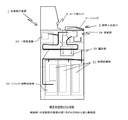
次に、実施例1の自動取引装置1のシャッタ構造を図4ないし図6の構造図を用いて以下詳細に説明する。なお、図4がシャッタ周辺の概観斜視図であり、図5が図4のX−X断面図であり、図6が図4のY−Y断面図を示している。 Next, the shutter structure of the automatic transaction apparatus 1 according to the first embodiment will be described in detail below with reference to the structural diagrams of FIGS. 4 is a schematic perspective view of the periphery of the shutter, FIG. 5 is an XX sectional view of FIG. 4, and FIG. 6 is a YY sectional view of FIG.
実施例1の自動取引装置1のシャッタ41は、図6に示したようにスロープ状となっており、図5のようにシャッタ41の両側側面に側壁面45が設けられ、この側壁面45が筐体カバー42に覆われる構造となっている。 The shutter 41 of the automatic transaction apparatus 1 according to the first embodiment has a slope shape as shown in FIG. 6, and side walls 45 are provided on both side surfaces of the shutter 41 as shown in FIG. The structure is covered by the housing cover 42.
また、図6左下に示したように、シャッタ下端部47は、シャッタ41を閉じたときに筐体カバー42に覆われる構成となっており、シャッタ下端部47を覆う筐体カバー42は、シャッタ面48より低い位置となるようになっている。 6, the shutter lower end 47 is configured to be covered by the housing cover 42 when the shutter 41 is closed, and the housing cover 42 that covers the shutter lower end 47 is the shutter. The position is lower than the surface 48.
シャッタ下端部47の下側には樋43が配置され、樋43は排水口44を有し、その先には排水口44からの水等を溜める水溜部53が設けられている。なお、水溜部53を設けることなく、水等をガイドして筐体に沿って落下させるようにすれば水溜部53を設けなくてもよい。
A
また、シャッタ上端51にも上端壁面52を有し、筐体カバー42に覆われる構造となっている。
Further, the shutter upper end 51 also has an upper
(動作)
以上の構成により、実施例1の自動取引装置のシャッタ41は以下のように動作する。
(Operation)
With the above configuration, the shutter 41 of the automatic transaction apparatus according to the first embodiment operates as follows.
まず、自動取引装置1の利用者が操作部4により、例えば、紙幣の入金取引を選択すると、主制御部20の制御に基づき、紙幣入出金口3のシャッタ41を開いて紙幣の投入を促す。このシャッタ41を開く動作では、図6に示したシャッタ動作46の矢印Hのようにシャッタ下端部47が上方に向かうように移動する。
First, when the user of the automatic transaction apparatus 1 selects, for example, banknote deposit transaction by the operation unit 4, the shutter 41 of the banknote deposit / withdrawal port 3 is opened based on the control of the
そして、一旦、シャッタ41を閉め、入金紙幣の計数を行い、正常に計数すると入金取引を終了する。このときのシャッタ41を閉める動作では、前述の開くときの動作の逆の動作となり、シャッタ下端部47が矢印Hとは反対方向に移動する。このように入出金取引を行わない状態では、シャッタ41が閉まった図6の状態が維持され、外部からの雨水や飲み物などの水等が装置内に流入することを防止する。 Then, the shutter 41 is once closed, the deposited banknote is counted, and when it is counted normally, the deposit transaction is terminated. The closing operation of the shutter 41 at this time is the reverse of the opening operation described above, and the shutter lower end 47 moves in the direction opposite to the arrow H. When the deposit / withdrawal transaction is not performed as described above, the state of FIG. 6 in which the shutter 41 is closed is maintained, and rainwater, water such as drinks, etc. from the outside are prevented from flowing into the apparatus.
そして、シャッタ41が閉まった状態で、シャッタ面48に水等がかかると、図5のようにシャッタ1の側面に側壁面45が設けられているので、水等はスロープ状になったシャッタ面48に沿って下側に流れる。 Then, when water or the like is applied to the shutter surface 48 with the shutter 41 closed, the side wall surface 45 is provided on the side surface of the shutter 1 as shown in FIG. It flows downward along 48.
このとき、シャッタ下端部47は、シャッタ面48より低い面からなる筐体カバー42で覆われているので、水等の大部分は図6矢印Dのようにシャッタ面48から筐体カバー面へと向かう主水路9を経て排水される。 At this time, since the shutter lower end portion 47 is covered with the housing cover 42 formed of a surface lower than the shutter surface 48, most of water and the like are transferred from the shutter surface 48 to the housing cover surface as shown by an arrow D in FIG. The water is drained through a main waterway 9 that faces.
残りの水等はシャッタ下端部47底面を覆う樋43に流れ、樋43に設けられた排水口44へと向かう副水路50を経て排水される。
The remaining water or the like flows into the
以上のように実施例1の自動取引装置1のシャッタ構造は作用するので、排水構造を大型化することなく十分な排水量を得ることができ、排水が追いつかなくなることもなく、シャッタ面48に水等が溜まることもない。 As described above, since the shutter structure of the automatic transaction apparatus 1 according to the first embodiment operates, a sufficient amount of drainage can be obtained without increasing the size of the drainage structure. Etc. do not accumulate.
また、シャッタ上端51にも上端壁面52を有し、筐体カバー42に覆われる構造となっているので、スロープの傾きが少ない水平状のシャッタ41においてもシャッタ上端51側から装置内に水等が流入することがない。
Further, since the shutter upper end 51 also has an upper
また、以上のように作用するので、甘味料の入った飲み物などをシャッタ41上にこぼし甘味料がシャッタ41上に付着した場合でも、多量の水をその上から流して甘味料を洗い流すこともできる。 In addition, since it acts as described above, even when a drink containing sweetener is spilled on the shutter 41 and the sweetener adheres to the shutter 41, a large amount of water can be poured from above to wash away the sweetener. it can.
(実施例1の効果)
以上詳細に述べたように実施例1の自動取引装置によれば、両側側面に側壁面を具備したスロープ状のシャッタと、当該シャッタの側壁面を覆い、シャッタを閉じたときにシャッタ面より低い位置でシャッタ下端部を覆う筐体カバーと、排水口を有し、シャッタを閉じたときに前記シャッタ下端部を下から覆うように配置した樋とを備えたので、排水構造を大型化することなく十分な排水量を得ることができ、排水が追いつかなくなることもなく、シャッタ面に水等が溜まることを防止することができる。
(Effect of Example 1)
As described in detail above, according to the automatic transaction apparatus of the first embodiment, the slope-shaped shutter having side wall surfaces on both side surfaces, the side wall surfaces of the shutter are covered, and the shutter surface is lower than the shutter surface when the shutter is closed. Since the housing cover that covers the lower end of the shutter at the position and the ridge that has a drain outlet and is arranged so as to cover the lower end of the shutter from below when the shutter is closed, the drainage structure should be enlarged. Therefore, it is possible to obtain a sufficient amount of drainage, prevent the drainage from catching up, and prevent water or the like from accumulating on the shutter surface.
以上述べたように、本発明は、シャッタを開閉し紙幣等の媒体を投入して所望の取引を行う現金自動預払機等の自動取引装置に広く用いることができる。 As described above, the present invention can be widely used in an automatic transaction apparatus such as an automatic teller machine that opens and closes a shutter and inserts a medium such as a bill to perform a desired transaction.
1 自動取引装置
2 硬貨入出金口
3 紙幣入出金口
4 操作部
20 主制御部
26 紙幣処理部
41 シャッタ
42 筐体カバー
43 桶
44 排水口
47 シャッタ下端
48 シャッタ面
49 主水路
50 副水路
51 シャッタ上端
52 壁面
DESCRIPTION OF SYMBOLS 1 Automatic transaction apparatus 2 Coin deposit / withdrawal port 3 Banknote deposit / withdrawal port 4
Claims (6)
当該シャッタの側壁面を覆い、シャッタを閉じたときにシャッタ表面より低い位置でシャッタ下端部を覆う筐体カバーと、
を有する、シャッタ構造。 A slope-like shutter having side wall surfaces on both side surfaces;
A housing cover that covers the side wall surface of the shutter and covers the lower end of the shutter at a position lower than the shutter surface when the shutter is closed;
A shutter structure.
Priority Applications (4)
| Application Number | Priority Date | Filing Date | Title |
|---|---|---|---|
| JP2010005301A JP5454155B2 (en) | 2010-01-13 | 2010-01-13 | Shutter structure and automatic transaction apparatus |
| US13/504,940 US8701859B2 (en) | 2010-01-13 | 2010-12-01 | Shutter structure and automatic transaction apparatus |
| PCT/JP2010/071497 WO2011086781A1 (en) | 2010-01-13 | 2010-12-01 | Shutter structure and automated transaction device |
| CN201080048225.4A CN102667876B (en) | 2010-01-13 | 2010-12-01 | Shutter structure and automated transaction device |
Applications Claiming Priority (1)
| Application Number | Priority Date | Filing Date | Title |
|---|---|---|---|
| JP2010005301A JP5454155B2 (en) | 2010-01-13 | 2010-01-13 | Shutter structure and automatic transaction apparatus |
Publications (3)
| Publication Number | Publication Date |
|---|---|
| JP2011145840A JP2011145840A (en) | 2011-07-28 |
| JP2011145840A5 JP2011145840A5 (en) | 2012-10-18 |
| JP5454155B2 true JP5454155B2 (en) | 2014-03-26 |
Family
ID=44304072
Family Applications (1)
| Application Number | Title | Priority Date | Filing Date |
|---|---|---|---|
| JP2010005301A Active JP5454155B2 (en) | 2010-01-13 | 2010-01-13 | Shutter structure and automatic transaction apparatus |
Country Status (4)
| Country | Link |
|---|---|
| US (1) | US8701859B2 (en) |
| JP (1) | JP5454155B2 (en) |
| CN (1) | CN102667876B (en) |
| WO (1) | WO2011086781A1 (en) |
Families Citing this family (7)
| Publication number | Priority date | Publication date | Assignee | Title |
|---|---|---|---|---|
| US10319171B2 (en) * | 2014-03-28 | 2019-06-11 | Ncr Corporation | Media escape prevention for self-service terminal |
| CN104112311A (en) * | 2014-05-06 | 2014-10-22 | 昆山古鳌电子机械有限公司 | Banknote separating mechanism |
| JP6303921B2 (en) * | 2014-08-25 | 2018-04-04 | 沖電気工業株式会社 | Media transaction equipment |
| CN104331977B (en) * | 2014-10-30 | 2017-01-11 | 东莞职业技术学院 | Paper currency multi-feature collecting system and method based FPGA |
| CN106228708A (en) * | 2016-07-15 | 2016-12-14 | 深圳怡化电脑股份有限公司 | Mutual door gear and bank note interactive device |
| CN108657563A (en) * | 2018-03-22 | 2018-10-16 | 苏州朗威电子机械股份有限公司 | A kind of intelligent cloud cabinet drainage system |
| US10049532B1 (en) * | 2018-04-26 | 2018-08-14 | Capital One Services, Llc | Automated teller machine (ATM) device with sealed slot |
Family Cites Families (6)
| Publication number | Priority date | Publication date | Assignee | Title |
|---|---|---|---|---|
| US4251009A (en) * | 1978-04-03 | 1981-02-17 | Mclaughlin Richard S | Security door assembly for an automatic document dispensing device |
| JPH0342528Y2 (en) | 1986-09-20 | 1991-09-05 | ||
| JPH06282724A (en) * | 1993-03-30 | 1994-10-07 | Hitachi Ltd | Automatic teller machine |
| JP3959297B2 (en) | 2002-04-10 | 2007-08-15 | 日立オムロンターミナルソリューションズ株式会社 | Banknote handling equipment |
| JP4185705B2 (en) * | 2002-05-24 | 2008-11-26 | 日立オムロンターミナルソリューションズ株式会社 | Banknote handling equipment |
| JP5039613B2 (en) * | 2008-03-06 | 2012-10-03 | 日立オムロンターミナルソリューションズ株式会社 | Transaction processing equipment |
-
2010
- 2010-01-13 JP JP2010005301A patent/JP5454155B2/en active Active
- 2010-12-01 WO PCT/JP2010/071497 patent/WO2011086781A1/en active Application Filing
- 2010-12-01 US US13/504,940 patent/US8701859B2/en active Active
- 2010-12-01 CN CN201080048225.4A patent/CN102667876B/en active Active
Also Published As
| Publication number | Publication date |
|---|---|
| CN102667876B (en) | 2015-04-01 |
| WO2011086781A1 (en) | 2011-07-21 |
| CN102667876A (en) | 2012-09-12 |
| US20120210916A1 (en) | 2012-08-23 |
| JP2011145840A (en) | 2011-07-28 |
| US8701859B2 (en) | 2014-04-22 |
Similar Documents
| Publication | Publication Date | Title |
|---|---|---|
| JP5454155B2 (en) | Shutter structure and automatic transaction apparatus | |
| JP3959297B2 (en) | Banknote handling equipment | |
| US10395224B2 (en) | Financial device having a replaceable module for performing replenishment or collection function | |
| JP5039613B2 (en) | Transaction processing equipment | |
| JP4910494B2 (en) | Automatic transaction equipment | |
| JP5251340B2 (en) | Coin deposit and withdrawal machine | |
| JP5564767B2 (en) | Automatic transaction equipment | |
| JP2010026646A (en) | Automatic transaction device | |
| JP2021086301A (en) | Medium processor and automated teller machine | |
| JP2013167936A (en) | Currency processing method, currency processing device, and currency processing system | |
| JP5928143B2 (en) | Medium input / output unit and medium transaction device | |
| JP4803273B2 (en) | Automatic teller machine | |
| JP4259441B2 (en) | Money processing equipment | |
| KR101709852B1 (en) | Financial device | |
| JP2004178455A (en) | Automatic transaction device | |
| JP4899630B2 (en) | Card dispensing device | |
| JP5277868B2 (en) | Automatic transaction equipment | |
| JP2008040533A (en) | Automatic vending machine | |
| KR101940733B1 (en) | Banknote storage and financial device thereof | |
| JP2007140705A (en) | Cash handling device | |
| JP5096231B2 (en) | Automatic cash transaction equipment | |
| JP6357977B2 (en) | Automatic ticketing machine | |
| JP3185375B2 (en) | Coin processing equipment | |
| KR20070071826A (en) | Method and device of recognizing the denomination of a note in an atm | |
| JPH11272911A (en) | Automatic teller machine executing foreign matter returning processing |
Legal Events
| Date | Code | Title | Description |
|---|---|---|---|
| A521 | Written amendment |
Free format text: JAPANESE INTERMEDIATE CODE: A523 Effective date: 20120904 |
|
| A621 | Written request for application examination |
Free format text: JAPANESE INTERMEDIATE CODE: A621 Effective date: 20120904 |
|
| TRDD | Decision of grant or rejection written | ||
| A01 | Written decision to grant a patent or to grant a registration (utility model) |
Free format text: JAPANESE INTERMEDIATE CODE: A01 Effective date: 20131210 |
|
| A61 | First payment of annual fees (during grant procedure) |
Free format text: JAPANESE INTERMEDIATE CODE: A61 Effective date: 20131223 |
|
| R150 | Certificate of patent or registration of utility model |
Ref document number: 5454155 Country of ref document: JP Free format text: JAPANESE INTERMEDIATE CODE: R150 Free format text: JAPANESE INTERMEDIATE CODE: R150 |