JP5453263B2 - Nailer - Google Patents
Nailer Download PDFInfo
- Publication number
- JP5453263B2 JP5453263B2 JP2010520401A JP2010520401A JP5453263B2 JP 5453263 B2 JP5453263 B2 JP 5453263B2 JP 2010520401 A JP2010520401 A JP 2010520401A JP 2010520401 A JP2010520401 A JP 2010520401A JP 5453263 B2 JP5453263 B2 JP 5453263B2
- Authority
- JP
- Japan
- Prior art keywords
- impact
- nail
- nailing
- rod
- nailer
- Prior art date
- Legal status (The legal status is an assumption and is not a legal conclusion. Google has not performed a legal analysis and makes no representation as to the accuracy of the status listed.)
- Active
Links
- 230000033001 locomotion Effects 0.000 claims description 27
- 230000007246 mechanism Effects 0.000 claims description 19
- 230000005540 biological transmission Effects 0.000 claims description 15
- 238000004146 energy storage Methods 0.000 claims description 11
- 230000009471 action Effects 0.000 claims description 7
- 230000035939 shock Effects 0.000 claims 2
- 241000587161 Gomphocarpus Species 0.000 claims 1
- 229910000831 Steel Inorganic materials 0.000 description 11
- 239000010959 steel Substances 0.000 description 11
- 238000011084 recovery Methods 0.000 description 8
- 238000000034 method Methods 0.000 description 5
- 230000000737 periodic effect Effects 0.000 description 5
- 241001079814 Symphyotrichum pilosum Species 0.000 description 4
- 235000004224 Typha angustifolia Nutrition 0.000 description 4
- 238000000926 separation method Methods 0.000 description 4
- 230000000694 effects Effects 0.000 description 3
- 230000008569 process Effects 0.000 description 3
- 230000008707 rearrangement Effects 0.000 description 2
- 230000006835 compression Effects 0.000 description 1
- 238000007906 compression Methods 0.000 description 1
- 239000000463 material Substances 0.000 description 1
- 230000004048 modification Effects 0.000 description 1
- 238000012986 modification Methods 0.000 description 1
- 238000005381 potential energy Methods 0.000 description 1
- 238000003825 pressing Methods 0.000 description 1
- 238000007789 sealing Methods 0.000 description 1
- 238000006467 substitution reaction Methods 0.000 description 1
Images


Classifications
-
- B—PERFORMING OPERATIONS; TRANSPORTING
- B25—HAND TOOLS; PORTABLE POWER-DRIVEN TOOLS; MANIPULATORS
- B25C—HAND-HELD NAILING OR STAPLING TOOLS; MANUALLY OPERATED PORTABLE STAPLING TOOLS
- B25C1/00—Hand-held nailing tools; Nail feeding devices
- B25C1/06—Hand-held nailing tools; Nail feeding devices operated by electric power
Description
本発明は、くぎ打ち機に関し、特に、電気くぎ打ち機に関する。 The present invention relates to a nail driver, and more particularly to an electric nail driver.
くぎ打ち機は、一般的に使用されている携帯用の工具である。くぎ打ち機は、動力源によって、空気くぎ打ち機と電気くぎ打ち機とに分けられる。その中、空気くぎ打ち機は、圧縮空気源を供えることが必要であるので、使用者に対して、異なる場所へ移動することが不便であり、その使用が制限される。電気くぎ打ち機は、一般にモーターの回転運動をノズルに設けられたくぎ打ちロッドの直線運動に変換する伝動機構を有する。くぎ打ち機のスイッチをオンにすると、電気エネルギーが往復運動である機械エネルギーに変換される。 A nailer is a commonly used portable tool. Nails are divided into air nails and electric nails according to the power source. Among them, since the air nailer needs to be provided with a compressed air source, it is inconvenient for the user to move to a different place, and its use is limited. An electric nail driver generally has a transmission mechanism that converts the rotational motion of a motor into linear motion of a nail rod provided on a nozzle. When the nail switch is turned on, electrical energy is converted into mechanical energy, which is a reciprocating motion.
特許文献1及び特許文献2には、バッテリーを電源とする電気くぎ打ち機が開示されている。この開示されているくぎ打ち機はモーターの回転運動を直線運動に変換するクランク−スライダー機構を有する。しかしながら、このようなくぎ打ち機は、押し動作クランクスライダー機構が実質的に押し動作とこのような押し動作のくぎ打ち効果が、同じモーターのパワーが与えられた場合、打ち動作のそれよりかなり低いという問題があった。他の問題は、押し動作ごとに、クランクスライダー機構は、押し素子を同じストライクで押し、くぎが硬いものに合って進行抵抗力が大きすぎると、モータが回転止めとなり、モータが損なわれる可能性があること。さらに、モータはハンドルの前方または後側に設けられたので、モーターと伝動機構との連結がわりに大きい空間を占有し、くぎ打ち機がその体積を大きくさせ、携帯および操作には不便になる。
特許文献3には、ラックピニオン機構によりモータの回転をばねを圧縮する力に変換し、解放手段により圧縮のばねを解放して、衝撃力を生じさせる伝動機構を有するくぎ打ち機が開示されている。このくぎ打ち機は、ばねによりエネルギーを貯蓄してくぎに対して瞬間的に打つことが達成できるが、毎回に一つの打撃を与え、連続的に打つことができず、かつ、ばねのみによりエネルギーを解放することにより、衝撃力の効率が高くないので、このくぎ打ち機が一般的に使用される工具として適用できなく、なお、そのモータはノズルの下方のハウジングにあり、ハンドルと完全的に離間し、装置がコンパクトでないという問題がある。
次に、連続的に打てる改良された電気くぎ打ち機について以下説明する。 Next, an improved electric nail driver that can be struck continuously will be described below.
このくぎ打ち機は、モータを収納するハウジングと、くぎ打ち装置とを含む。伝動機構はハウジング内に設けられ、これはモータの回転運動をくぎ打ち装置の周期的な衝撃動作に変換する。この伝動機構は前記くぎ打ち装置に対して周期的な衝撃動作を付与する衝撃アセンブリをさらに含む。 This nail driving machine includes a housing that houses a motor and a nail driving device. A transmission mechanism is provided in the housing, which converts the rotational movement of the motor into the periodic impact motion of the nailing device. The transmission mechanism further includes an impact assembly that provides periodic impact motion to the nailing device.
前記くぎ打ち装置は、打たれたくぎの頭部と接触可能な打ち部分と、衝撃アセンブリと接触可能な被衝撃部分とを含む。 The nailing device includes a striking portion that can contact the head of the struck nail and an impacted portion that can contact the impact assembly.
くぎ打ち装置は、ハウジングに対して往復運動をする往復部材を含む。 The nailing device includes a reciprocating member that reciprocates relative to the housing.
さらに、衝撃アセンブリは回転軸線を有している回転衝撃部材を含む。この回転衝撃部材は、くぎ打ち装置の被衝撃部分と周期的に接触する少なくとも一つの衝撃部分を含む。 Further, the impact assembly includes a rotational impact member having a rotational axis. The rotary impact member includes at least one impact portion that periodically contacts the impacted portion of the nailing device.
明らかなように、モータの回転運動は本くぎ打ち装置中で、回復装置の補助と共にくぎ打ち装置の往復打ち運動に変換される。従って、モータが回転し続ける間、伝動機構を通してモータの回転運動を衝撃アセンブリのくぎ打ち装置に対する周期的な衝撃動作に変換することにより、くぎ打ち装置が連続的に往復運動し、くぎに対する連続な打ちを達成する。 As can be seen, the rotational motion of the motor is converted in the nailing device into the reciprocating motion of the nailing device with the aid of the recovery device. Therefore, while the motor continues to rotate, the nailing device continuously reciprocates by converting the rotational motion of the motor through the transmission mechanism into a periodic impact motion to the nailing device of the impact assembly, so that Achieve a strike.
本発明のくぎ打ち機は、よりコンパクトな構造で、効率的、連続的な打ち動作が達成され、これは従来技術のシングルストライク又はショットタイプくぎ打ち機の欠点を克服する。この従来技術と比べ、本発明のくぎ打ち機は、実質的に異なり、改良されており、さまざまな仕事環境に適用される。
本願発明の趣旨、メリット、機能、特性と、以下に開示する電気くぎ打ち機との関係のより正しい認識は、下記の詳細な説明及び種々の方法を示す実施例の添付図面から明らかになる。
The nailer of the present invention has a more compact structure and achieves an efficient and continuous strike operation, which overcomes the shortcomings of prior art single strike or shot type nailers. Compared to this prior art, the nail driver of the present invention is substantially different and improved, and is applicable to various work environments.
A more accurate recognition of the spirit, merits, functions, and characteristics of the present invention and the relationship between the electric nailers disclosed below will become apparent from the following detailed description and the accompanying drawings of the embodiments showing various methods.
本くぎ打ち機のより深い理解ため次の図面を参照する。 For a deeper understanding of the nailer, refer to the following drawings.
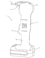
第一の実施形態のくぎ打ち機1は、図1、図2に示すように、モータ2を収納するハウジング3とノズル部分4とを含む。ハウジング3は第一の半ハウジング31と第二の半ハウジング32を合せてなり、収納空間を形成している。ハウジング3の主体上に長尺状のグリップを形成されている。ハウジング3の上部に穴が有り、この穴にノズル部分4の少なくとも一部が挿通されている。
As shown in FIGS. 1 and 2, the
くぎ打ち機1は、モータ2に電力を提供するバッテリーパック5を含む。しかしながら、くぎ打ち機1の給電手段としては、DC電力に限定されず、AC電力源によっても同様に給電できる。スイッチ6は、モータ2のコントロールのためハウジング3に取り付けられている。ノズル部分4は、回復ばね42中を通してくぎ7を打つ一本のくぎ打ちロッド41を含む。くぎ打ちロッド41は、ハウジング3の本体の垂直にしっかり配置され、ノズル部分4中で往復運動する。くぎ打ちロッド41は、第一端部411と第二端部413を有している。操作する際、くぎ打ちロッド41は、駆動され、その第一端部411の端面をくぎ7の頭部に作用させている。ノズル部分4は、伸縮可能な蓄くぎ装置43をさらに有し、蓄くぎ装置43は、少なくともくぎの頭部を収納するための切り込み431を有している。例として、くぎ7を切り込み431に付着させるため、蓄くぎ装置43中に図に示されていない磁石を含んでいてもよい。切り込み431は、通常のくぎの径よりも大きい寸法を有しているので、様々な形、大きさのくぎも蓄くぎ装置の切り込み431内に置かれる。
The
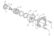
図3ないし図7に示すように、ハウジング3中には、伝動機構が装着され、この機構は、モータ2の回転運動をくぎ打ちロッド41の衝撃運動に変換する。モータ2はモーターシャフト21を含み、その中心軸線はハウジング3の主体部分の縦長方向に位置し、または、ハウジング3の主体部分の縦長方向に対して平行している。モーターシャフト21は、かさ歯車を含む多段歯車伝動機構に接続している。この方法で、モータ2の回転動力は、ハウジング3の上部に両端がベアリングにて支持された回転軸8に伝達する。回転軸8には、一対の斜溝9が設けられ、各斜溝9は概してV字状をなす。衝撃輪10は、回転軸8に挿通され、ほぼ中空の円柱をなす。衝撃輪10は、その円柱内面には、それぞれ両斜溝9の位置と対向する一対の円弧状案内溝11が設けられている。各案内溝11の円弧の開口方向は、それと対向するV字状の斜溝9の開口方向と逆にされる。斜溝9と案内溝11とはいずれも半円弧底を有している。一対の鋼球12は、斜溝9と案内溝11により形成される2つのチェンバー中に移動可能に配置される。斜溝9が案内溝11に関連して移動するとき、これにより形成されるチェンバーはチェンバーと一緒に移動する鋼球12と共に移動する。そして、回転軸8が回転する際、斜溝9内にある鋼球12を介して案内溝11に対して圧力を付与することに連れて衝撃輪10を回転させている。蓄エネルギーばね13は、衝撃輪10と回転軸8との間に装着され、その一端が回転軸8の段差部81に当接され、その他端が衝撃輪10の一つの側面に当接されている。段差部81及び衝撃輪10上の蓄エネルギーばね13の軸方向のバイアス力下では、図7の実線部分に示すように、
回転軸8及び衝撃輪10が静止及びアイドリングのとき、鋼球12がV字状の斜溝9の上末端および案内溝11の底端に位置している。
このとき、衝撃輪10は、回転軸8に対する第一軸方向位置にある。
As shown in FIGS. 3 to 7, a transmission mechanism is mounted in the
When the
At this time, the
図2および図4に示すように、一対の止めピン15は、ハウジング3内に固定されているとともに、衝撃輪10の外周の近くにある。回転輪10の外周には、直径方向に沿って伸びる対の突起14が備えられることが好ましい。スイッチ6をオンにしたとき、モータ2が起動し、多段歯車伝動体を介して伝動し、回転軸8が回転し、さらに、回転軸8が斜溝9および鋼球12、案内溝11、蓄エネルギーばね13の連動により衝撃輪10を回転させている。図7に示すように、衝撃輪10がある位置まで回転して突起14を止めピン15と接触させる時、止めピン15が一時的に衝撃輪10の回転を阻止する(このとき、衝撃輪10における案内溝11、鋼球12および回転軸8における斜溝9が図7の実線に示す位置にある)。回転軸8がさらに回転することが、斜溝9を矢印Aの方向に沿って図7における破線に示す位置まで回転させる。そして、衝撃輪10そして、鋼球12が斜溝9に沿ってV字状の斜溝9の頂端へ移動させられる。その結果、衝撃輪10はその軸に沿って第二軸方向位置まで移動し、蓄エネルギーばね13を圧縮する(このとき、衝撃輪10の案内溝11、鋼球12および斜溝9、は図7の破線に示す位置にある)。
言うまでもなく、衝撃輪10は、移動中、回転軸8に対して、一定の回転遅れがある。この第二軸位置においては、突起14は止めピン15から離れているので、衝撃輪10の回転は止めピン15により、もはや止めることはできない。蓄エネルギーばね13の回復力により、衝撃輪10が第一軸位置へ急速に押し戻る。斜溝9、案内溝11および鋼球12の連動により、回転軸8が衝撃輪10を再回転させる。移動過程に逆転する再配置過程中、衝撃輪10が回転軸8と過剰に関連しているので、再配置過程中衝撃輪10は、回転軸8より回転数が速い。くぎ打ちの効果を改善するため、衝撃輪実質的に当初の位置(例えば、第一軸位置)に戻った後その突起がくぎ打ちロッドと衝突するため、蓄エネルギーばねの強度は、モータの回転速度数とあわせるのが好ましい。
その結果、くぎ打ちロッド41の第二端部413は衝撃輪10における突起14に衝突して、突起14から離れる方向に高速に移動し、くぎ打ちロッド41の第一端部411が瞬間にくぎ7の頭部を衝突する。この方法で繰り返しくぎ打ちアクションは達成される。突起14連続して回転させられ止めピン15と接触するとき、衝撃輪10が回転を止め、再び続く衝撃周期に入る。くぎ打ちロッド41がくぎ7に向かって移動する間に、回復ばね42が圧縮される。くぎ打ちが終了したとき、くぎ打ちロッド41は、回復ばね42の回復力により、元の位置へ戻る。
As shown in FIGS. 2 and 4, the pair of retaining
Needless to say, the
As a result, the
説明したように、回転軸8および衝撃輪10は同一の回転軸線を有する。突起14がくぎ打ちロッド41の第二端部413を衝突した時、衝撃力の方向は衝撃輪10の回転軸に対して垂直である。好ましくは、通常の第二端部413の表面の接触方向は衝撃輪10の回転軸に対して垂直である。
As described, the
本実施の形態では、二つの方向に傾斜する凹所からなるV字状の斜溝9と、V字状の斜溝9の開口方向とは逆にした円弧状の案内溝11は、互いに合せるよう選択することが好ましい。しかしながら、使用中は、V字状の溝のみが役に立つ。同一の方向の衝撃動作を達成させる時に、V字状の斜溝9の一側の斜溝のみが役に立つ。従って、斜溝は、達成できるくぎ打ち動作の一方向に傾斜したのみの凹部を提供する。
In the present embodiment, the V-shaped
最初に述べた実施形態では、直接にくぎを打つくぎ打ち装置は、長尺状のロッド41である。それは、評価されるだろうが、そのくぎ打ち装置は、同じ効果を達成できる異なる形状と構造と共に他の構成要素に置換できる。
In the first-described embodiment, the nailing device that directly strikes the nail is a
同様に、衝撃輪における突起は、突起の接触部分とロッドが衝撃輪の軸から離れている限り、衝撃輪の他の位置でもよい。例えば、突起は衝撃輪の一つの側面に位置してもよい。さらに、衝撃輪は異なる形状と構成を有する衝撃部材に代えてもよい。例えば、衝撃材はほぼ杆状に作成され、それは穴を通して回転軸に設けられ、その少なくとも一端が前記衝撃輪の突起として機能する。
図示したように、本実施形態では、打ちロッド41は、ハウジングの回復ばね42により生み出される付勢下、内側に向かって押される。この方法では、くぎ打ち装置がオンとするやいなやロッド41は衝撃輪10により衝撃が与えられる。その他の実施の形態では、くぎ打ち機には、ハウジング内部に向かう力を付与していないとき、衝撃部材がそのロッドと接触しないように、くぎ打ち装置に対してハウジングの外部に向かう力を付与する、ばねまたはその他の種類の回復装置が設けてもよい。このように、くぎ打ち装置がアイドリングのとき、衝撃装置とくぎ打ち装置間の磨耗が低減され、装置の寿命が延長される。
その他の実施の形態では、くぎ打ち装置に力がかかっていないときに、くぎ打ち装置がノズルのその他の部分に対して現状位置を保ち、衝撃手段とくぎ打ち装置との接触部分の磨耗を減少させるため、くぎ打ち装置とノズル部分のその他の部分との間に摩擦部材(例えば、ゴム封止リングおよび形状適宜なゴム部材)が設けられてもよい、
Similarly, the protrusions on the impact wheel may be at other positions on the impact wheel as long as the contact portion of the protrusion and the rod are separated from the axis of the impact wheel. For example, the protrusion may be located on one side of the impact wheel. Further, the impact wheel may be replaced with an impact member having a different shape and configuration. For example, the impact material is formed in a substantially bowl shape, which is provided on the rotating shaft through the hole, and at least one end thereof functions as a projection of the impact wheel.
As shown, in this embodiment, the striking
In other embodiments, the nailing device maintains its current position relative to the rest of the nozzle when no force is applied to the nailing device, reducing wear on the contact portion between the impact means and the nailing device. Therefore, a friction member (for example, a rubber sealing ring and a rubber member having an appropriate shape) may be provided between the nail driving device and the other portion of the nozzle portion.
第一の実施形態では、実際に、くぎ打ち機における止めピンが除去されてもよい。その理由は下述した第二の実施形態で説明する。 In the first embodiment, the stop pin in the nail driver may actually be removed. The reason will be described in the second embodiment described below.
図8〜図10に、本発明の第二の実施形態のくぎ打ち機を示す。第一の実施形態と第二の実施形態の外観はお互い明らかに異なる。第二の実施形態のくぎ打ち機のハウジング30が、バッテリーパックを取り外しとき、T字状をなし、モータ20がハウジング30の水平及びノズル部分40の後側に配置される。しかし、第二の実施形態のくぎ打ち機と第一の実施形態とくぎ打ち機は、伝動機構および動作の原理はほぼ同一であるので、ここではその詳細な説明をする必要はない。
8 to 10 show a nail driver according to the second embodiment of the present invention. The appearances of the first embodiment and the second embodiment are clearly different from each other. When the battery pack is removed, the
いくつかの構成要素の形状の差異に加えて、第一と第二の実施形態明らかな相違は、第二の実施形態のくぎ打ち機には止めピンがないことである。実際の操作中、くぎを硬い物体に打つとき、または、目的物に完全に打ち込んだ場合、くぎ打ちロッドが大きい抵抗力を受けて最大ストロークまで達してないうちに停止することがある。このとき、くぎ打ちロッドの衝撃輪と接触している端部が、衝撃輪の止めピンと同様に機能し、凹溝及びその中の噛合部材(例えば、鋼球)の作用により、衝撃輪が蓄エネルギーばねを圧縮する第二軸位置に向かって回転軸に対して軸方向に動く。一度、衝撃輪が、くぎ打ちロッドとの接触がない第二軸位置に着くために移動すると、蓄エネルギーばねの弾性位置エネルギーが解放され、凹溝及びその中の噛合部材の作用により、回転軸の通常の回転数より速い回転数で衝撃輪が回転させられる。、その回転エネルギーにより、衝撃輪はくぎ打ちロッドに強く衝撃を与え、再びに効果的にくぎ打ちロッドを打つことができる。 In addition to the differences in the shape of several components, the obvious difference between the first and second embodiments is that the nail driver of the second embodiment has no stop pins. During actual operation, when a nail is hit against a hard object or when it is completely driven into a target object, the nail rod may stop before reaching the maximum stroke due to a large resistance force. At this time, the end portion of the nailing rod that is in contact with the impact wheel functions in the same manner as the impact ring retaining pin, and the impact wheel is stored by the action of the concave groove and the meshing member (for example, a steel ball) therein. It moves axially relative to the axis of rotation towards a second axis position that compresses the energy spring. Once the impact wheel moves to reach the second axis position where there is no contact with the nailing rod, the elastic potential energy of the energy storage spring is released, and the rotating shaft is rotated by the action of the concave groove and the meshing member therein. The impact wheel is rotated at a rotational speed faster than the normal rotational speed. Due to the rotational energy, the impact wheel gives a strong impact to the nailing rod, and can effectively strike the nailing rod again.
そして、止めピンがない場合、くぎ打ち装置は、抵抗力が一定の範囲を超えた場合に限り、止めピンとして機能する。くぎ打ち機の回転軸が均一に回転している間、衝撃装置は、自身が一時に停止したり、高速回転したり、周期的に変速運動する。
そして、くぎ打ち装置は、衝撃装置によって周期的な衝撃を受ける。このようにして、第一の実施形態のくぎ打ち機の止めピンを除去することができることが理解される。
And when there is no stop pin, the nail driving device functions as a stop pin only when the resistance exceeds a certain range. While the rotation shaft of the nailer is rotating uniformly, the impact device stops at once, rotates at a high speed, or periodically performs a variable speed movement.
The nail driving device receives a periodic impact by the impact device. In this way, it is understood that the stop pin of the nail driver of the first embodiment can be removed.
第二の実施形態におけるばね130、420と第一の実施形態におけるばね13、42を、その他の種類のバイアス部材または引力と斥力をつくるための他の手段、例えば、磁性部材に置換してもよい。
The
第二の実施形態における衝撃輪100と第一の実施形態における衝撃輪10を、ピストン、遠心装置またはくぎ打ちロッドに衝撃を与えるばねに置換することができる。
The
第一の実施形態と第二の実施形態において、衝撃装置は、くぎ打ちに装置に周期的に衝撃を与え、くぎ打ち装置は、直線往復運動する。どころが、本分野の当業者は、次のことが容易に理解されるであろう。くぎ打ち装置はレバー機構に置換でき、その一端は衝撃装置によって、回転軸回りに回転されるよう衝撃を受け、他端は、くぎを打つことができる。この場合、くぎ打ち装置が、衝撃装置の周期的な衝撃により往復振動する。 In the first embodiment and the second embodiment, the impact device periodically impacts the nails with the device, and the nails perform a linear reciprocating motion. On the contrary, those skilled in the art will readily understand the following. The nail driving device can be replaced with a lever mechanism, and one end of the nail driving device receives an impact to be rotated around the rotation axis by the impact device, and the other end can hit the nail. In this case, the nailing device vibrates reciprocally due to the periodic impact of the impact device.
以上、種々の代替案を述べたが、本発明のくぎ打ち機は前記実施の形態に記載の内容および図面に示す構成に限定されないことが判る。従って、本発明の精神の下のいかなる置換や修正は本発明の範囲に入るとみなされるであろう。 Although various alternatives have been described above, it is understood that the nailing machine of the present invention is not limited to the contents described in the above embodiments and the configuration shown in the drawings. Accordingly, any substitution or modification within the spirit of the present invention will be deemed to fall within the scope of the present invention.
Claims (14)
モータを収納するハウジング、
くぎを打つためのくぎ打ちロッドを含むノズル部、及び
前記モータの回転運動を前記くぎ打ちロッドの衝撃運動に変換する前記ハウジング内の伝動機構を有し、
前記伝動機構は、前記くぎ打ちロッドに対して衝撃運動を付与する衝撃アセンブリを有し、
前記衝撃アセンブリは、更に
前記モータにより駆動される回転軸;
前記回転軸に装着され、前記くぎ打ちロッドの被衝撃部分と接触する少なくとも一つの衝撃部分を持つ、回転衝撃部材;
前記回転軸に設けられた斜溝と前記回転衝撃部材に設けられた前記斜溝に対向する円弧状案内溝;
前記斜溝と円弧状案内溝により形成されたチェンバー内に移動可能に配置された、噛合部材;及び
前記回転軸の一端と前記回転衝撃部材との間に装着された蓄エネルギーばね、
を有し、
前記斜溝、前記円弧状案内溝及び前記噛合部材は、前記モータに駆動されて前記回転軸が回転するとともに前記チェンバー内で前記噛合部材が移動することにより、前記円弧状案内溝に対して圧力を付与して前記回転衝撃部材を回転させるように配置されており、
前記回転衝撃部材は、回転しながら前記回転軸に対して第一軸位置と第二軸位置の間を移動することができ、
前記第一軸位置において、前記回転衝撃部材の衝撃部分は前記くぎ打ちロッドの被衝撃部分と接触可能であり、かつ前記蓄エネルギーばねは解放されており、ここで、前記回転軸が回転すると、前記噛合部材からの圧力により前記回転衝撃部材は前記第二軸位置へと移動して前記蓄エネルギーばねを圧縮し、
前記第二軸位置において、前記回転衝撃部材の衝撃部分は前記くぎ打ちロッドの被衝撃部分と接触せず、かつ前記蓄エネルギーばねは圧縮されており、ここで、前記回転軸が回転すると、前記噛合部材からの圧力と圧縮された前記蓄エネルギーばねの作用により前記回転衝撃部材は前記第一軸位置へと移動する、
くぎ打ち機。 A nailer,
A housing for housing the motor,
Nozzle portion including a nailing rod for striking a nail, and has a transmission mechanism in said housing for converting the rotary motion of the motor to impact movement of the striking rod,
The transmission mechanism includes a shock assembly for imparting impact movement relative to the striking rod,
The impact assembly further comprises a rotating shaft driven by the motor ;
Mounted before Symbol rotation axis, one lifting at least one impact portion in contact with the impacted portion of the striking rod, rotating impact member;
Arcuate guide groove facing the oblique groove provided in the rotating impact member and Hasumizo was set eclipse to the rotating shaft;
It is movably disposed in front Symbol Hasumizo an arcuate guide the chamber formed by the groove, the engaging member; and
An energy storage spring mounted between one end of the rotary shaft and the rotary impact member ;
Have
The oblique groove, the arcuate guide groove, and the meshing member are driven by the motor to rotate the rotating shaft and move the meshing member in the chamber, whereby pressure is applied to the arcuate guide groove. Is arranged so as to rotate the rotary impact member,
The rotation impact member can move between a first axis position and a second axis position with respect to the rotation axis while rotating,
In the first shaft position, the impact portion of the rotary impact member can contact the impacted portion of the nailing rod, and the energy storage spring is released, where the rotation shaft rotates, The rotational impact member moves to the second shaft position by the pressure from the meshing member and compresses the energy storage spring,
In the second shaft position, the impact portion of the rotary impact member does not contact the impacted portion of the nailing rod, and the energy storage spring is compressed, and when the rotation shaft rotates, The rotational impact member moves to the first shaft position by the action of the pressure from the meshing member and the compressed energy storage spring.
Nailer.
Applications Claiming Priority (7)
| Application Number | Priority Date | Filing Date | Title |
|---|---|---|---|
| CN200720042846 | 2007-08-14 | ||
| CN200720042846.7 | 2007-08-14 | ||
| CN200720182700.2 | 2007-09-29 | ||
| CN200720182700 | 2007-09-29 | ||
| CN200820117509.4 | 2008-06-17 | ||
| CN200820117509 | 2008-06-17 | ||
| PCT/CN2008/001425 WO2009021398A1 (en) | 2007-08-14 | 2008-08-05 | Nailer device |
Publications (3)
| Publication Number | Publication Date |
|---|---|
| JP2010535642A JP2010535642A (en) | 2010-11-25 |
| JP2010535642A5 JP2010535642A5 (en) | 2011-09-22 |
| JP5453263B2 true JP5453263B2 (en) | 2014-03-26 |
Family
ID=40350358
Family Applications (1)
| Application Number | Title | Priority Date | Filing Date |
|---|---|---|---|
| JP2010520401A Active JP5453263B2 (en) | 2007-08-14 | 2008-08-05 | Nailer |
Country Status (6)
| Country | Link |
|---|---|
| US (3) | US7789282B2 (en) |
| EP (1) | EP2176035B1 (en) |
| JP (1) | JP5453263B2 (en) |
| AU (1) | AU2008286608B2 (en) |
| CA (1) | CA2694555C (en) |
| WO (1) | WO2009021398A1 (en) |
Cited By (1)
| Publication number | Priority date | Publication date | Assignee | Title |
|---|---|---|---|---|
| TWI644765B (en) * | 2018-07-11 | 2018-12-21 | 朝程工業股份有限公司 | Impact tool |
Families Citing this family (20)
| Publication number | Priority date | Publication date | Assignee | Title |
|---|---|---|---|---|
| US7789282B2 (en) | 2007-08-14 | 2010-09-07 | Chervon Limited | Nailer device |
| US7963430B2 (en) * | 2008-10-15 | 2011-06-21 | Chervon Limited | Nailer device |
| CN201493818U (en) * | 2009-07-17 | 2010-06-02 | 南京德朔实业有限公司 | Nail gun |
| CN201525003U (en) * | 2009-11-02 | 2010-07-14 | 南京德朔实业有限公司 | Electric hammer |
| CN201525005U (en) * | 2009-11-05 | 2010-07-14 | 南京德朔实业有限公司 | Electric hammer |
| CN201659545U (en) * | 2009-11-09 | 2010-12-01 | 南京德朔实业有限公司 | Electric hammer |
| US8469250B2 (en) * | 2009-11-19 | 2013-06-25 | Chervon Limited | Auto hammer |
| CN102069480B (en) * | 2009-11-21 | 2012-10-10 | 南京德朔实业有限公司 | Powered hammer |
| WO2011103320A2 (en) * | 2010-02-19 | 2011-08-25 | Milwaukee Electric Tool Corporation | Impact device |
| US20110308829A1 (en) * | 2010-06-18 | 2011-12-22 | Jiangsu Hehui Electronic Tools Co., Ltd. | Nail gun |
| US9259832B2 (en) * | 2010-08-25 | 2016-02-16 | Makita Corporation | Handheld electrical power tools |
| CN102689288A (en) * | 2011-03-23 | 2012-09-26 | 苏州宝时得电动工具有限公司 | Automatic nailing gun |
| CN202021588U (en) * | 2011-03-29 | 2011-11-02 | 南京德朔实业有限公司 | Electric hammer |
| US20120261152A1 (en) * | 2011-04-13 | 2012-10-18 | Chervon (Hk) Limited | Auto hammer |
| US10149711B2 (en) | 2012-03-30 | 2018-12-11 | Depuy Mitek, Llc | Surgical impact tool |
| US20160158819A1 (en) * | 2014-12-03 | 2016-06-09 | Paul E. Johnson | Compact Pneumatic Auto Body Hammer with Fine Control of Impact Force |
| CN206140421U (en) * | 2016-10-19 | 2017-05-03 | 东莞百事得电动工具有限公司 | Impact structure |
| DE102018218144A1 (en) * | 2018-10-23 | 2020-04-23 | Techway Industrial Co., Ltd. | Striking tool |
| US11945084B2 (en) | 2021-04-26 | 2024-04-02 | Snap-On Incorporated | Offset impact mechanism for a hammer tool |
| TWI791263B (en) * | 2021-08-17 | 2023-02-01 | 力肯實業股份有限公司 | Nail driving device of electric nailing machine |
Family Cites Families (48)
| Publication number | Priority date | Publication date | Assignee | Title |
|---|---|---|---|---|
| US1860826A (en) * | 1929-08-19 | 1932-05-31 | Black & Decker Mfg Co | Hammer rectilinear reciprocation |
| US2002762A (en) * | 1934-02-12 | 1935-05-28 | Resilent Hammer Inc | Electric hammer |
| US2079909A (en) * | 1934-09-26 | 1937-05-11 | Jackson Corwill | Vibrating motor |
| US2500402A (en) | 1945-07-11 | 1950-03-14 | Craig Ernest | Rotary vibratory hammer |
| US2877820A (en) * | 1956-12-17 | 1959-03-17 | Milwaukee Electric Tool Corp | Power hammer |
| US3160217A (en) * | 1962-11-30 | 1964-12-08 | Richard R Raihle | Mechanical hammer |
| US3376940A (en) * | 1966-05-10 | 1968-04-09 | Richard K. Willis | Powered hand hammer |
| US3486569A (en) | 1968-05-06 | 1969-12-30 | Black & Decker Mfg Co | Impact mechanism |
| US4042036A (en) * | 1973-10-04 | 1977-08-16 | Smith James E | Electric impact tool |
| US3924692A (en) * | 1974-02-06 | 1975-12-09 | Illinois Tool Works | Fastener driving tool |
| US4114699A (en) | 1976-01-22 | 1978-09-19 | Licentia Patent-Verwaltungs-Gmbh | Pneumatic rotary hammer device |
| DE2654521A1 (en) * | 1976-12-01 | 1978-06-08 | Mey Kg Maschf Mafell | NAIL DEVICE |
| US4299021A (en) * | 1979-11-19 | 1981-11-10 | Williams Luther M | Axial impact tool |
| DE3311265A1 (en) | 1983-03-28 | 1984-10-11 | Hilti Ag, Schaan | ELECTROPNEUMATIC DRILL AND CHISEL HAMMER |
| US4625903A (en) * | 1984-07-03 | 1986-12-02 | Sencorp | Multiple impact fastener driving tool |
| DE3427614A1 (en) * | 1984-07-26 | 1986-01-30 | Hilti Ag, Schaan | DRIVING DEVICE FOR NAILS AND THE LIKE FASTENING ELEMENTS |
| DE3504650C2 (en) | 1985-02-12 | 1994-01-20 | Bosch Gmbh Robert | Hammer drill with increased actuation force for the coupling of the impact drive |
| JPS62124883A (en) | 1985-11-26 | 1987-06-06 | 芝浦メカトロニクス株式会社 | Rotary hammer |
| US4742875A (en) * | 1986-03-19 | 1988-05-10 | Bell Joseph P | Motor-driven hammer |
| DE3883436T2 (en) * | 1987-06-17 | 1993-12-09 | Yamada Juki Kk | Rotating impact device. |
| US5002869A (en) * | 1987-11-02 | 1991-03-26 | Dana-Farber Cancer Institute | Monoclonal antibody specific to a novel epitope of the LFA-1 antigen of human T lymphocytes |
| US4834278A (en) * | 1988-06-13 | 1989-05-30 | Lin Chung Cheng | Structure of dc motorized nailing machine |
| JPH0295582A (en) | 1988-09-30 | 1990-04-06 | Hitachi Koki Co Ltd | Impact drill |
| US4908909A (en) * | 1989-04-06 | 1990-03-20 | Fendo Oy | Meathammer |
| US4953774A (en) * | 1989-04-26 | 1990-09-04 | Regitar Power Tools Co., Ltd. | Electric stapling gun with auto-reset, energy-saving and shock-absorbing functions |
| JPH03129212U (en) * | 1990-04-10 | 1991-12-25 | ||
| GB9126338D0 (en) | 1991-12-11 | 1992-02-12 | Glynwed Eng | Fastener applicator |
| US5794325A (en) * | 1996-06-07 | 1998-08-18 | Harris Corporation | Electrically operated, spring-biased cam-configured release mechanism for wire cutting and seating tool |
| DE19742916A1 (en) | 1997-09-29 | 1999-04-01 | Westfalia Werkzeug | Control for an electric motor operated on a voltage network with two mains connections |
| US6431430B1 (en) | 1998-09-18 | 2002-08-13 | Stanley Fastening Systems, L.P. | Battery operated roofing nailer and nails therefor |
| JP2000198087A (en) * | 1998-12-29 | 2000-07-18 | Yamada Kikai Kogyo Kk | Continuously impacting machine |
| JP2000308850A (en) * | 1999-04-26 | 2000-11-07 | Kawasaki Heavy Ind Ltd | Impact generator |
| US6213222B1 (en) | 2000-01-06 | 2001-04-10 | Milwaukee Electric Tool Corporation | Cam drive mechanism |
| CA2303648A1 (en) * | 2000-03-31 | 2001-09-30 | Paulhus, Gerald J. | Percussion tool |
| US20020079111A1 (en) * | 2000-12-21 | 2002-06-27 | Camp Vincent J. | Electric hammer |
| US6604666B1 (en) * | 2001-08-20 | 2003-08-12 | Tricord Solutions, Inc. | Portable electrical motor driven nail gun |
| US6866226B2 (en) * | 2001-10-04 | 2005-03-15 | Hartwell Corporation | Pressure responsive blowout latch |
| CA2479979C (en) * | 2002-07-25 | 2007-03-13 | Yih Kai Enterprise Co., Ltd. | Handy electric nailing gun |
| CN2601790Y (en) * | 2003-01-26 | 2004-02-04 | 巫宗进 | Device for nailing cement nails |
| US6959478B2 (en) | 2003-11-01 | 2005-11-01 | Ting-Kuang Chen | Shockproof spindle |
| JP4200918B2 (en) | 2004-02-09 | 2008-12-24 | 日立工機株式会社 | Drilling machine |
| DE102004010319B3 (en) * | 2004-03-03 | 2005-08-04 | Hilti Ag | Electromagnetic striking-in device for nails has power store chargeable in two ways with magnetic coil in different positions |
| US7322506B2 (en) * | 2004-04-02 | 2008-01-29 | Black & Decker Inc. | Electric driving tool with driver propelled by flywheel inertia |
| AU2005263992A1 (en) | 2004-07-23 | 2006-01-26 | Gavin Beales | Nailer device |
| US7104432B2 (en) * | 2004-08-09 | 2006-09-12 | An Puu Hsin Co., Ltd. | Transmission mechanism of electric nailing gun |
| CN100351047C (en) | 2004-11-05 | 2007-11-28 | 茂纲实业股份有限公司 | Electric driven nailing gun capable of shooting one by one |
| US7263920B1 (en) | 2004-12-15 | 2007-09-04 | Norris A Hamilton | Torque impact wrench |
| US7789282B2 (en) | 2007-08-14 | 2010-09-07 | Chervon Limited | Nailer device |
-
2008
- 2008-08-01 US US12/184,392 patent/US7789282B2/en not_active Ceased
- 2008-08-05 CA CA2694555A patent/CA2694555C/en active Active
- 2008-08-05 EP EP08783614.4A patent/EP2176035B1/en active Active
- 2008-08-05 WO PCT/CN2008/001425 patent/WO2009021398A1/en active Application Filing
- 2008-08-05 AU AU2008286608A patent/AU2008286608B2/en active Active
- 2008-08-05 JP JP2010520401A patent/JP5453263B2/en active Active
-
2010
- 2010-04-15 US US12/761,040 patent/US8342375B2/en active Active
-
2012
- 2012-05-17 US US13/506,854 patent/USRE44344E1/en active Active
Cited By (1)
| Publication number | Priority date | Publication date | Assignee | Title |
|---|---|---|---|---|
| TWI644765B (en) * | 2018-07-11 | 2018-12-21 | 朝程工業股份有限公司 | Impact tool |
Also Published As
| Publication number | Publication date |
|---|---|
| AU2008286608A1 (en) | 2009-02-19 |
| US20090045241A1 (en) | 2009-02-19 |
| CA2694555C (en) | 2012-10-16 |
| EP2176035B1 (en) | 2017-09-27 |
| JP2010535642A (en) | 2010-11-25 |
| US20100193562A1 (en) | 2010-08-05 |
| US7789282B2 (en) | 2010-09-07 |
| EP2176035A1 (en) | 2010-04-21 |
| WO2009021398A1 (en) | 2009-02-19 |
| EP2176035A4 (en) | 2016-09-14 |
| AU2008286608B2 (en) | 2013-06-20 |
| USRE44344E1 (en) | 2013-07-09 |
| CA2694555A1 (en) | 2009-02-19 |
| US8342375B2 (en) | 2013-01-01 |
Similar Documents
| Publication | Publication Date | Title |
|---|---|---|
| JP5453263B2 (en) | Nailer | |
| JP5514217B2 (en) | Nailer | |
| JP2010535642A5 (en) | ||
| US20110114696A1 (en) | Auto hammer | |
| US8596512B2 (en) | Clamping mechanism for an electric hammer | |
| CN101407049B (en) | Nailing gun | |
| CN201271876Y (en) | Nailing gun | |
| US20050006428A1 (en) | Nailing gun | |
| EP1504850A2 (en) | Nailing gun | |
| CN117733795A (en) | Nail driving mechanism and nail gun | |
| CA2721619A1 (en) | Auto hammer |
Legal Events
| Date | Code | Title | Description |
|---|---|---|---|
| A521 | Request for written amendment filed |
Free format text: JAPANESE INTERMEDIATE CODE: A523 Effective date: 20110803 |
|
| A621 | Written request for application examination |
Free format text: JAPANESE INTERMEDIATE CODE: A621 Effective date: 20110803 |
|
| A977 | Report on retrieval |
Free format text: JAPANESE INTERMEDIATE CODE: A971007 Effective date: 20130306 |
|
| A131 | Notification of reasons for refusal |
Free format text: JAPANESE INTERMEDIATE CODE: A131 Effective date: 20130319 |
|
| A521 | Request for written amendment filed |
Free format text: JAPANESE INTERMEDIATE CODE: A523 Effective date: 20130618 |
|
| TRDD | Decision of grant or rejection written | ||
| A01 | Written decision to grant a patent or to grant a registration (utility model) |
Free format text: JAPANESE INTERMEDIATE CODE: A01 Effective date: 20131224 |
|
| A61 | First payment of annual fees (during grant procedure) |
Free format text: JAPANESE INTERMEDIATE CODE: A61 Effective date: 20140106 |
|
| R150 | Certificate of patent or registration of utility model |
Ref document number: 5453263 Country of ref document: JP Free format text: JAPANESE INTERMEDIATE CODE: R150 Free format text: JAPANESE INTERMEDIATE CODE: R150 |
|
| R250 | Receipt of annual fees |
Free format text: JAPANESE INTERMEDIATE CODE: R250 |
|
| R250 | Receipt of annual fees |
Free format text: JAPANESE INTERMEDIATE CODE: R250 |
|
| R250 | Receipt of annual fees |
Free format text: JAPANESE INTERMEDIATE CODE: R250 |
|
| R250 | Receipt of annual fees |
Free format text: JAPANESE INTERMEDIATE CODE: R250 |
|
| R250 | Receipt of annual fees |
Free format text: JAPANESE INTERMEDIATE CODE: R250 |
|
| R250 | Receipt of annual fees |
Free format text: JAPANESE INTERMEDIATE CODE: R250 |
|
| R250 | Receipt of annual fees |
Free format text: JAPANESE INTERMEDIATE CODE: R250 |
|
| R250 | Receipt of annual fees |
Free format text: JAPANESE INTERMEDIATE CODE: R250 |