JP5452996B2 - Elastic shell structure of chair - Google Patents
Elastic shell structure of chair Download PDFInfo
- Publication number
- JP5452996B2 JP5452996B2 JP2009152080A JP2009152080A JP5452996B2 JP 5452996 B2 JP5452996 B2 JP 5452996B2 JP 2009152080 A JP2009152080 A JP 2009152080A JP 2009152080 A JP2009152080 A JP 2009152080A JP 5452996 B2 JP5452996 B2 JP 5452996B2
- Authority
- JP
- Japan
- Prior art keywords
- elastic
- base
- base portion
- slit
- chair
- Prior art date
- Legal status (The legal status is an assumption and is not a legal conclusion. Google has not performed a legal analysis and makes no representation as to the accuracy of the status listed.)
- Active
Links
Images


Description
本発明は、椅子の身体を支える構造物(本明細書では、身体支持構造物と呼ぶ)に関する。更に詳述すると、本発明は、椅子の背もたれや座などの身体支持構造物に構造的に弾力性を持たせる弾性シェル構造に関する。 The present invention relates to a structure that supports the body of a chair (referred to herein as a body support structure). More specifically, the present invention relates to an elastic shell structure that provides structural support to a body support structure such as a chair back or seat.
従来の背もたれや座などの身体を支える椅子の構造物においては、弾力性を持たせるため、プラスチック製シェルの上に熱硬化性ウレタンフォームを厚く発泡させ、さらに上張り地で覆うことが一般的である。しかしながら、発泡した熱硬化性ウレタンフォーム製品は通常、リサイクルできないものとして分類され、リサイクル可能な材料やより天然の材料と比べて、環境に優しくないと一般的に考えられている。したがって、熱硬化性発泡体を排除すること、即ち発泡ウレタンフォームは排除することが、椅子を100%リサイクル可能にすることに向けて重要なステップの1つと考えられている。また、快適性の点において必ずしも十分でないという問題がある。即ち、発泡体は通気性が無いとともに、厚い発泡体クッションを設けるだけでは、一定領域に必要な分散支持レベルを与えることができないため満足できる解決にはならない。さらに、「適切な」支持を行うのに十分な厚さの発泡体クッションは、薄く均整美を持つ外観を有するように設計された椅子には美的に合わない。そこで、リサイクル可能な部品や再溶融可能な熱可塑性樹脂などのリサイクル可能な材料を使用するのに最適な構造の弾性シェル構造が望まれている。 Conventional chair structures that support the body, such as a backrest or seat, are generally foamed with a thermoset urethane foam on a plastic shell and covered with an upholstery to provide elasticity. It is. However, foamed thermoset urethane foam products are usually classified as non-recyclable and are generally considered less environmentally friendly than recyclable or more natural materials. Therefore, eliminating the thermosetting foam, i.e. eliminating the urethane foam, is considered one of the important steps towards making the chair 100% recyclable. There is also a problem that it is not always sufficient in terms of comfort. That is, the foam is not breathable, and simply providing a thick foam cushion does not provide a satisfactory solution because it cannot provide the required dispersed support level in a certain area. Furthermore, a foam cushion that is thick enough to provide “appropriate” support is not aesthetically pleasing to a chair that is designed to have a thin and well-balanced appearance. Therefore, an elastic shell structure having an optimum structure for using recyclable materials such as recyclable parts and remeltable thermoplastic resins is desired.
そこで、近年、椅子の背もたれや座などの身体を支える構造物そのものに弾力性を持たせるため、弾力性のあるメッシュ状の膜(伸張布地)を樹脂製フレームに張り詰めて固定することにより、フレームの内側に弾力面を構成するようにした座や背もたれを構成するものが提案されたり(特許文献1)、座板や背もたれなどの身体支持構造物にスリットを入れることによって構造物そのものに柔軟性・可撓性を与える技術が提案されている(特許文献2,3)。例えば、合板または適当なプラスチックから成る座あるいは背もたれを構成する板状材料において、柔軟性を高めるために、椅子の長手方向または垂直方向に向けられた多数のスリットを入れることによって当該板状材料を互いに独立した個々の平行な帯板に分割し、座板または背もたれの横方向の柔軟性を高めて利用者の体形への整合を改善しようとしたり(特許文献2参照)、パッド部材を支えるシートフレームの基板部分の弾力性を増させるために、基板部分と枠板部分とを備えたシートフレームをプラスチックで一体形成し、このシートフレームの基板部分に櫛歯状のスリットあるいは多数の円形孔を開けて可撓性を付与するようにしている(特許文献3参照)。
Therefore, in recent years, in order to give elasticity to the structure itself that supports the body such as the backrest and seat of the chair, by attaching an elastic mesh film (stretch fabric) to the resin frame and fixing it, Proposals have been made to construct a seat or backrest with a resilient surface inside the frame (Patent Document 1), or by making slits in the body support structure such as a seat plate or backrest, the structure itself can be flexibly Techniques for imparting flexibility and flexibility have been proposed (
しかしながら、特許文献1のメッシュ状の膜(伸張布地)を樹脂製フレームに張ることによって弾力的な支持面を得ようとする場合、膜の張力が不足するとユーザが布地材に沈み込んで「捕らえられる」ようになり、 それによる側部圧力を感じることになる。この「ハンモック様」感覚を防止するのに必要な張力は相当に大きく、布地に十分な張力を掛けるために許容量の強度を与えるには、非常に強いフレームが必要である。そして、「ハンモック」様感覚を回避するのに十分な大きさでなければならないことである。さらに、フレーム内の布地にプリテンションを掛ける処理は、より困難な製造ステップとなる。また、高張力をかけた布地を支持するために必要なフレーム強度は、特殊材料及び大きい断面寸法を必要とし、製品の重量及びコストを増加させる。 However, when trying to obtain an elastic support surface by stretching the mesh-like membrane (stretch fabric) of Patent Document 1 on a resin frame, if the membrane tension is insufficient, the user sinks into the fabric material and “captures” You will feel the pressure on the side. The tension required to prevent this “hammock-like” sensation is quite large, and a very strong frame is required to provide an acceptable amount of strength to apply sufficient tension to the fabric. And it must be large enough to avoid a “hammock” -like sensation. Further, pretensioning the fabric in the frame is a more difficult manufacturing step. Also, the frame strength required to support high tension fabrics requires special materials and large cross-sectional dimensions, increasing the weight and cost of the product.
また、特許文献2や3の発明のように、座板や背もたれなどの構造物にスリットを入れて剛性を部分的に低下させることにより可撓性・弾力性を持たせようとしても、樹脂によって形成された背もたれあるいは座などは着座者の体重を支持する構造物としての剛性が同時に要求される為、形状の変化はあまり大きなものにはできない。つまり、単純に身体を支える構造物にスリットをいれるだけでは、十分な弾力性と剛性・強度との両立が達成できない。十分な弾力性を得るには、構造的に柔軟な構造とする必要があり、それは同時に構造体としての基本的な剛性を損なうことになるからである。
In addition, as in the inventions of
本発明は、基本的な剛性は確保しつつソフトな座り心地を得る椅子の弾性シェル構造を提供することを目的とする。 An object of the present invention is to provide an elastic shell structure of a chair that ensures a soft sitting comfort while ensuring basic rigidity.
かかる目的を達成するために請求項1記載の椅子の弾性シェル構造は、樹脂成形板から成る椅子の身体支持構造物において、少なくとも弾力性を与えようとする領域に構造物としての基本的な剛性を担うベース部と該ベース部とは段違いに形成され当該構造物に弾力性を与える弾力部とを立体的に分けて形成し、前記ベース部によって形成されるベース面と前記弾力部によって形成される弾力面との互いに独立した2つの面を構成し、前記ベース面に対し前記弾力面が相対的に前方に突出し前記ベース面とは段違いに形成されると共に、前記弾力部に挟まれた前記ベース部は帯状を成している。 In order to achieve this object, the elastic shell structure of a chair according to claim 1 is a basic rigidity as a structure in a body support structure of a chair made of a resin-molded plate. The base part which bears the base and the base part are formed in three steps, and the elastic part which gives elasticity to the structure is formed in three dimensions, and is formed by the base surface formed by the base part and the elastic part And two elastic surfaces that are independent of each other, the elastic surface protrudes relatively forward with respect to the base surface, is formed in a step difference from the base surface, and is sandwiched between the elastic portions. the base portion has formed a band.
また、請求項2記載の発明は、請求項1記載の椅子の弾性シェル構造において、身体支持構造物の周縁部がベース部によって構成され、弾力部がその両端をベース部に繋がった帯状に形成されるようにしている。 According to a second aspect of the present invention, in the elastic shell structure of the chair according to the first aspect, the peripheral portion of the body support structure is formed by a base portion, and the elastic portion is formed in a belt shape in which both ends thereof are connected to the base portion. To be.
また、請求項3記載の発明は、請求項1または2記載の椅子の弾性シェル構造において、弾力部とベース部とが交互に形成されているものである。
The invention according to
また、請求項4記載の発明は、請求項1から3のいずれか1つに記載の椅子の弾性シェル構造において、ベース部と弾力部との間にはスリットが入れられ、ベース部と弾力部とが並び方向には分離されているものである。 According to a fourth aspect of the present invention, in the elastic shell structure for a chair according to any one of the first to third aspects, a slit is provided between the base portion and the elastic portion, and the base portion and the elastic portion. Are separated in the arrangement direction.
また、請求項5記載の発明は、請求項4記載の椅子の弾性シェル構造において、身体支持構造物に上張り地が被せられて弾力部とベース部との間のスリットが上張り地で覆われるようにしている。 According to a fifth aspect of the present invention, in the elastic shell structure of the chair according to the fourth aspect, the upper support is covered with the body support structure, and the slit between the elastic portion and the base is covered with the upper support. It is to break.
また、請求項6記載の発明は、請求項1から3のいずれか1つに記載の椅子の弾性シェル構造において、弾力部とベース部との間の間隙が膜で連結されるようにしている。 According to a sixth aspect of the present invention, in the elastic shell structure of the chair according to any one of the first to third aspects, the gap between the elastic portion and the base portion is connected by a film. .
さらに、請求項7記載の発明は、請求項1から6のいずれか1つに記載の椅子の弾性シェル構造において、弾力部に局部的に変形を促す屈曲部を備えるようにしている。
Further, the invention of
請求項1記載の椅子の弾性シェル構造によると、構造物としての基本的な剛性を担うベース部と該ベース部に対して相対的に前方に突出するように段違いに形成された弾力部とで、ベース面と弾力面との互いに独立した2つの面を段違いに立体的に分けて構成しているので、同一面内で単純にスリットを入れる場合に比べて撓める部分がより大きく確保できる。しかも、基本的な剛性を確保するベース部と撓ませるための弾力部とを予め切り分けて設計できるので、基本的な剛性を確保することが容易であると共に剛性部分だけで所望の剛性が得られるように設計できる。したがって、体感上撓みが実感できる程度の十分な弾力性を得る柔軟な構造と、構造物として要求される必要十分な剛性・強度の構造との両立が可能となる。つまり、椅子としての強さを確保しつつ着座者の体重に応じて撓み易くなる。また、構造物としての強度と弾力性を与える弾性シェル構造としての強度とを切り分けて設計できることから、設計・製造が容易となる。特に、弾力部並びにスリットを形成する方向を適宜変更することで異なる撓み・変形の身体支持構造物が得られる。 According to the elastic shell structure of the chair according to claim 1, the base portion that bears the basic rigidity as the structure and the elastic portion that is formed so as to protrude forward relative to the base portion. Since the two independent surfaces of the base surface and the elastic surface are divided in three dimensions in a stepwise manner, a larger bending portion can be ensured than in the case where a slit is simply inserted in the same surface. . In addition, since it is possible to design the base portion for securing the basic rigidity and the elastic portion for bending in advance, it is easy to ensure the basic rigidity and the desired rigidity can be obtained only by the rigid portion. Can be designed as Therefore, it is possible to achieve both a flexible structure that obtains sufficient elasticity that allows the user to actually feel the bending and a structure having the necessary and sufficient rigidity and strength required as a structure. That is, it becomes easy to bend according to a seated person's weight, ensuring the strength as a chair. Further, since the strength as the structure and the strength as the elastic shell structure that gives elasticity can be separated and designed, the design and manufacture become easy. In particular, different flexure / deformation body support structures can be obtained by appropriately changing the direction of forming the elastic portion and the slit.
さらに、ベース面に対して当該構造物に弾力性を与える弾力面が前方に突出するように段違いに形成されているため、弾力部が荷重を受けることで大きく変形したとしても、ベース面に身体を支える面が広がることで応力集中が回避される。また、ベース面に対して弾力面が前方に突出するようにベース部と弾力部とが段違いに形成されているため、これらの段差によって生じる溝に沿って空気が流れるため、通気性が良くなる。 Further, since the elastic surface that gives elasticity to the structure with respect to the base surface is formed so as to protrude forward, even if the elastic portion is greatly deformed by receiving a load, the body surface is Stress concentration is avoided by spreading the surface that supports Further, since the base portion and the elastic portion are formed in steps so that the elastic surface protrudes forward with respect to the base surface, air flows along a groove formed by these steps, so that air permeability is improved. .
また、請求項4記載の弾性シェル構造によると、段違いに形成されたベース部と弾力部との間にはスリットが入れられ、ベース部と弾力部とが並び方向に分離されているので、ベース部と弾力部との間のスリットを介して空気が通過するので、通気性が確保される。 According to the elastic shell structure of the fourth aspect , the slit is inserted between the base portion and the elastic portion formed in steps, and the base portion and the elastic portion are separated in the alignment direction. Since air passes through the slit between the portion and the elastic portion, air permeability is ensured.
また、請求項5記載の発明によると、身体支持構造物に上張り地が被せられて弾力部とベース部との間のスリットが上張り地で覆われるようにしているので、スリットを介しての通気性が確保しつつ上張り地がネットとなって弾力部とベース部との間に衣服や身体の一部が挟み付けられることを阻止する。 According to the fifth aspect of the present invention, the body support structure is covered with the upholstery so that the slit between the elastic portion and the base is covered with the upholstery. While the air permeability is secured, the upholstery serves as a net to prevent clothes and a part of the body from being sandwiched between the elastic part and the base part.
また、請求項6記載の発明によると、弾力部とベース部との間が膜で連結されているので、弾力部とベース部との間に衣服や身体の一部が挟み付けられることはない。しかも、ベース面に対して弾力面が前方に突出するようにベース部と弾力部とが段違いに形成されているため、これらの段差によって生じる溝に沿って空気が流れるため、通気性も損なわれることはない。
According to the invention described in
さらに、請求項7記載の発明によると、局部的に変形を促す屈曲部を弾力部に備えるようにしているので、ベース部に対して肉厚を大きく変化させなくとも、弾力部を撓みやすくできる。 Further, according to the seventh aspect of the present invention, since the elastic portion is provided with the bent portion that promotes deformation locally, the elastic portion can be easily bent without greatly changing the thickness with respect to the base portion. .
以下、本発明の構成を図面に示す実施形態に基づいて詳細に説明する。 Hereinafter, the configuration of the present invention will be described in detail based on embodiments shown in the drawings.
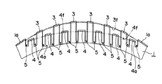
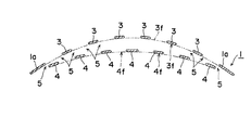
図1〜図3に本発明にかかる椅子の弾性シェル構造の一実施形態を背もたれに適用した例を挙げて説明する。この実施形態にかかる背もたれ1は、少なくとも弾力性を与えようとする領域2に構造物としての基本的な剛性を担うベース部3と該ベース部3とは段違いに形成され当該構造物に弾力性を与える弾力部4とを立体的に分けて形成し、ベース部3によって形成されるベース面3fと弾力部4によって形成される弾力面4fとの互いに独立した2つの面を構成し、ベース面3fに対し弾力面4fが相対的に前方に突出しベース面3fとは段違いに形成されるようにしている。
1 to 3 will be described with reference to an example in which an embodiment of the elastic shell structure of a chair according to the present invention is applied to a backrest. The backrest 1 according to this embodiment includes a
本実施形態における背もたれ1は、1つの樹脂成形品によって構成されるシェルであり、ほぼ全域において肉厚が等しい樹脂成形板として所望の形状に成形され、弾力性を与えようとする領域2に構造物としての基本的な剛性を担うベース部3と該ベース部3とは段違いに形成され当該構造物に弾力性を与える弾力部4とが射出成型時に前後に分けて立体的に形成されている。尚、背もたれ1の下端から着座者の腰部(背支点)付近にかけての縁部1bが弾力性を与えようとする領域2の外の周縁部1a並びに他の縁部に比べて肉厚に形成されることによって、背もたれとしての強度が補強されている。また、背もたれ1の上端縁1cも背面側に折り返されるフランジとされることで補強されている。勿論、これら肉厚の縁部1bやフランジ状の上端縁1cが必要とされないこともあれば、弾力部4とベース部3とを含む弾力性を与えようとする領域2を除いた周縁部分を弾力性を与えようとする領域2とは別素材あるいは別部材によって構成することによって高剛性の構造とすることも可能である。尚、本実施形態における背もたれは、例えばPET(ポリエチレンテレフタレート)やPP(ポリプロピレン)等のオレフィン系樹脂やナイロン系樹脂、ポリエステル系樹脂などにガラス繊維が添加されたガラス繊維強化熱可塑性プラスチックによって形成されている。
The backrest 1 in the present embodiment is a shell formed of one resin molded product, and is formed in a desired shape as a resin molded plate having an equal wall thickness in almost the entire region, and has a structure in a
ここで、本実施形態における背もたれ1の弾力性を与えようとする領域2における横断面形状は、図2及び図3に示すように、帯状に形成された弾力部4が横方向(背もたれの幅方向)に連なることによって形成される弾力面4fと、同様にベース部3が横方向に連なることによって形成されるベース面3fとの2つの面を形成し、かつ弾力面4fがベース面3fに対し相対的に前方に突出し段違いに形成されるように設けられている。また、この背もたれ1の弾力性を与えようとする領域2における縦断面形状は、図1に示すように、弦のようにほぼ直線上に形成されている弾力部4と、後方へ向けて突出するように湾曲した弓形に形成されているベース部3とで構成され、ベース部3に対して相対的に弾力部4が前方へ突出するように形成されている。
Here, as shown in FIGS. 2 and 3, the cross-sectional shape in the
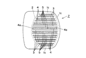
弾力部4とベース部3とは、図1並びに図8の(A)に示すように、スリット5によって互いに前後方向に切り離され、独立した動きを採りうるように設けられている。つまり、弾力部4惹いては弾力面4fの撓み・変形は構造物としての基本的な剛性を担うベース部3並びに周縁部1aから成る基板には伝播されず、またベース部3並びに周縁部1aから成る基板の剛性は弾力部4の可撓性に影響を与えない。ここで、スリット5は、図1〜図3に示す実施形態では、背もたれ1の高さ方向に直線的に入れられているが、これに特に限定されるものではなく、任意の形状、幅、方向にいれることができる。即ち、弾力部3並びにベース部は、図示の帯状の形態に限られず、必要に応じて任意の形状、幅、方向に形成することができる。
As shown in FIG. 1 and FIG. 8A, the
即ち、図9に示すようにスリット5を横方向に入れて幅方向に帯状となった弾力部4とベース部3とを形成しても良い。この場合、背もたれ1の高さ方向に反力の度合い・撓み易さを変化させ得るという効果がある。また、スリット5は直線状に限られず一方向に向けて湾曲させたり蛇行させたりしても良い。この場合にも、弾力部の弾力性を損なうことはない。例えば図9(B)に示すように、上向きに突出するように湾曲させても良い。さらには、スリット5の配列ピッチ即ち弾力部4並びにベース部3の幅も一定である必要はなく、対象となる身体支持構造物に求められる弾力性の分布に応じて適宜選定するようにしても良い。本実施形態の場合、背中の上部側のピッチを小さくして弾力部4の帯の幅を狭くして撓み易くする一方、腰部寄りのピッチを大きくして弾力部4の帯の幅を広げて撓み難くし、大きな反力を要する腰部での撓みやすさを抑えるようにしている。
That is, as shown in FIG. 9, the
また、スリット5の長さ惹いてはそれらの間で構成される弾力部4並びにベース部3の帯の長さや幅を適宜変更することも可能である。例えば、図10(A)に示すように短い弾力部4と長い弾力部4とを交互に形成しても良いし、幅が狭い弾力部4と幅が広い弾力部4とを交互に配置しても良い。また、場合によっては、背もたれの中央には幅広の弾力部4が備えられ、周辺に向かうに従って幅狭の弾力部4が設けられるようにしても良い。さらには、異なる長さの弾力部(惹いてはスリット5)4を配置する場合にも、弾力部4の上端あるいは下端のいずれか一方を同じ高さに揃えて短い弾力部4と長い弾力部4とを交互に配置したり、あるいは順次長さが長くなるように若しくは短かくなるように弾力部4を配置したり、あるいは上下両端のいずれも揃えずに中央を基準に両端が凹凸を繰り返すように配置したりしても良い。このように異なる長さや幅、形状の弾力部4や配置位置を適宜組み合わせることで、好みの分布で撓みやすい部分と撓みにくい部分とを設けることができる。
In addition, the length of the
また、ベース部3に対して相対的に突出する弾力部4に、弾力部4とベース部3とを区画するスリット5とは別のスリット5’をさらに入れて、弾力部4の撓み易さを調整するようにしても良い。さらには、十分な剛性を有するベース部3の場合にもスリット5’が入れられることもある。例えば図10(B)に示すように、弾力部4とベース部3とを区画する幅広のスリット5の間に狭い幅のスリット5’を入れて、狭い幅のスリット5’の両側の帯を同一方向へ相対的に突出させることで、弾力部4とベース部3とを交互に形成している。この場合には、弾力部4の中央に細いスリット5’が入れられることにより、幅広の弾力部4であっても十分に湾曲させることができる。また、ベース部3にスリット5’を入れることで、ベース部3の軽量化を図ると共にスリットを通して後方から視認できる為、湾曲状態を見せるデザイン的効果がある。尚、本実施形態では弾力部4とベース部3の双方に狭い幅のスリット5’を入れているが、場合によっては弾力部4あるいはベース部3のいずれか一方にのみスリット5’を入れるようにしても良い。
Further, the
さらに、スリット5は縦や横に限られず、図11に示すように放射状に形成するようにしても良い。この場合、中心と周辺とでスリット5の間に形成される弾力部4やベース部3の帯の幅が周辺に向かう程幅広となるので、中央が撓みやすく、周辺側が撓みにくくなる。勿論、スリットそのものを周辺側ほど広げることで弾力部4やベース部3の帯の幅をほぼ一定とした放射状の弾力部4とベース部3の構成としても良い。また、図示していないが、斜め方向に直線的なスリットを上下方向あるいは横方向に平行に配置して、帯状の弾力部4やベース部3を形成するようにしても良い。例えば帯状の弾力部4並びにベース部3を左右にハの字形に配置して2列の弾力面4fとベース面3fとを前後に形成するようにしても良い。
Further, the
さらに、上述の各実施形態の弾力部4及びベース部3は、弾力性を与えようとする領域2の範囲内において長手方向に1本の帯で構成されるようにしているが、これに特に限られるものではなく、長手方向に複数本の帯を配置するようにして複数の弾力面4fを形成するようにしても良い。例えば、図示していないが、背もたれ1の上下に分けて、あるいは背もたれ1の左右に分けて弾力部4を同一方向へ2列ずつあるいは3列以上形成しても良い。
Furthermore, the
さらに、上述の例示では、縦あるいは横若しくは放射状ないし斜めにそれぞれ1本あるいは2本以上の帯状の弾力部4やベース部3を交互に形成した場合について述べたが、これに特に限定されるものでなく、例えば間隔を開けて弾力部4あるいはベース部3を連続的に形成するようにしても良い。
Furthermore, in the above-described example, the case where one or two or more belt-like
さらに、本実施形態では、弾力部4とベース部3とを区画するスリット5は、一定の幅を有するものとして描かれているが、必ずしも一定の幅を必要とせず、スリットの幅や設置間隔を変更することにより、幅の異なる帯状の弾力部4やベース部3を任意に配置したり、場合によっては弾力部4とベース部3とが相対的に逆方向に突出することにより生じる裂け目によって形成されることもある。
Furthermore, in the present embodiment, the
このベース面3fと弾性面4fとの2つの面に立体的に分けて構成する帯状のシェルは、完全に抜けたスリットを設けることによって前後に分離されて段違いに形成されている。しかしながら、このスリット部分は、完全に貫通している必要はなく、場合によっては背もたれよりはさらに可撓性に富む材料例えばナイロン、ポリエステル、ウレタンなどのフィルムのような薄膜で連結するようにしても良い。例えば、図4及び図5に示すように、弾力部4とベース部3とが膜6で連結されることもある。この場合における膜6は、可撓性に富む材質・膜厚であることが望まれ、例えばナイロン、ポリエステル、ウレタン製フィルムなどの使用が好ましい。これにより、弾力部4とベース部3との間のスリット5が塞がれつつ、弾力部4の変形を可能とする。勿論、膜6が存在しスリット5が塞がれているといっても、弾力部4とベース部3との間を貫通するスリット5がないという意味であって、弾力部4とベース部3とを互いに前後方向に独立した動きを採りうるように切り離すといった意味でのスリット5は存在することは言うまでもない。しかも、弾力部4とベース部3との間にユーザーの衣服や身体の一部が挟まれるのを未然に防止できる。膜6は弾力部4並びにベース部3と同一素材により射出成形により一体的に形成しても良いが、一般に極端な肉厚の差を設けることは射出成形において好ましくない問題を引き起こすことから、別素材のフィルムなどを用いてインサート成型あるいは2色成型によって弾力部4とベース部3との間を連結する膜6を形成することが好ましい。
The band-shaped shell formed by three-dimensionally dividing the two surfaces, that is, the
さらに、弾力部4には、場合によっては、図8(C)あるいは(D)に示すように、屈曲部10が設けられ、局部的に変形し易い箇所を設けることで弾力性を調整したり、撓みやすい箇所を予め定めておくことも可能である。この屈曲部は、図8(C)に示すように断面半円環状でも良いし、図8(D)に示すように矩形状でも良い。この場合には、弾力部4そのものの肉厚を厚くしても、屈曲部10の部分の肉厚を薄くすることで撓みやすくすることができる。また、図8(B)に示すように、支柱11を設けて、弾力部4とベース部3とを局部的に繋ぐようにしても良い。この支柱11は弾力部4とベース部3の上下方向のほぼ中間点に設けられ、弾力部4の変形の支点として機能させられる。支柱11を支点として弾力部4の上部(支柱11よりも上の部分)を凹ませることにより弾力部4の下部(支柱11よりも下の部分)が凸となり、またその逆の変形も起こすことができる。このような場合、椅子に凭れて仰向けになる際には背中を大きく伸ばすことができる。尚、図8の(A)は図1の背もたれの弾力部4とベース部3との関係を示す。
Further, as shown in FIG. 8 (C) or (D), the
以上のように構成された本発明の弾性シェル構造によると、着座したユーザーが背もたれにもたれかかると、弾力部4が連なることによって形成される弾力面4fによって身体が支持され、弾力部4惹いては弾力面4fが撓んで変形することによって弾力性が与えられる。他方、背もたれ1の構造物としての基本的な剛性はベース部3並びにその周囲の周縁部1aで構成される基板が受け持つので、身体は安定的に支持される。そして、弾力部4によって構成される弾力面4fの撓み加減即ち弾力具合は、弾力部4の板厚や形状即ち帯状シェルの幅や突出量、屈曲度合い・変形具合などの変更で調整することができる。
According to the elastic shell structure of the present invention configured as described above, when the seated user leans against the backrest, the body is supported by the
なお、上述の形態は本発明の好適な形態の一例ではあるがこれに限定されるものではなく本発明の要旨を逸脱しない範囲において種々変形実施可能である。例えば、本実施形態における背もたれ1は、1つの樹脂成形品によって構成されるシェル構造としているが、全体が1つ樹脂成形品であることに特に限られず、少なくとも弾力部4とベース部3並びにその周縁を含む弾力性を与えようとする領域2の辺りが1つの樹脂成形品によって構成し、さらにその周りの枠部分については別パーツ(単純に部品として分離されている場合に限らず、二色成形のような別工程・別素材で構成される場合も含む)で構成することも可能である。少なくとも、弾力部4とベース部3並びにその周辺を1つ樹脂成形品で一体成形する場合には、一体成形による成形の簡単化、部品点数の削減によるコストの低減、容易に部品を交換できる、並びに同じ成形品であるため廃棄がしやすいなどの効果を有する。
The above-described embodiment is an example of a preferred embodiment of the present invention, but is not limited thereto, and various modifications can be made without departing from the scope of the present invention. For example, the backrest 1 in the present embodiment has a shell structure constituted by one resin molded product, but is not particularly limited to being a single resin molded product as a whole, and at least the
また、図4並び図5に示すように弾力部4とベース部3との間を膜6で連結する構造に代えて、上張り地(図示省略)を被せて弾力部4とベース部3との間のスリット5を覆うようにしても良い。具体的には、袋状の上張り地(図示省略)を被せて弾力部4とベース部3との間のスリット5を覆うようにしても良い。この場合にも、上張り地が弾力部4とベース部3との間のスリット5に挟み込まれるのを阻止するネットとして機能するため、スリット5を介しての通気性を確保しつつ弾力部4とベース部3との間のスリット5に衣服や身体の一部が挟まれるのを防止できる。この場合の上張り地は、例えば一端が開口された弾力性生地から成る袋状を成し、背もたれ1の上方からすっぽり被せるように装着させてから開口縁部を係止手段で閉じることにより固定することが可能である。弾力性生地としては、必要に応じて適宜選択される適度な弾力性と張力を発揮し得る素材、例えばポリエステルエラストマーやポリウレタンエラストマー等の樹脂フィルムないしシートや、更に樹脂フィルムをポリアミド等の繊維やタフタ等の編み物で補強したフィルムないしシート、布地、不織布等が適用可能である。勿論、前面側から上張り地を被せて背面側で上張り地の周縁を背もたれ1の周縁部1cに固定するようにしても良い。
4 and FIG. 5, instead of the structure in which the
さらに、本実施形態では、主に背もたれ1を例に挙げて本発明の弾性シェル構造を説明したが、これに特に限定されるものではなく、座やヘッドレスト、肘掛け、ランバーサポートなどの他の身体支持構造物にも適用できることは言うまでもない。例えば、図12に示すように、座7に適用することも可能である。この場合には、例えば着座時の快適性をユーザーに与えるため、臀部があたる領域を弾力性が与えられる領域2として弾力部4とベース部3とを設けることが好ましい。そこで、臀部があたる領域を中心とした弾力性が与えられる領域2にスリット5を入れて1つ置きに座の上側に突出する帯状の弾性シェル4を形成すると共に、弾性シェル4の間に水平かあるいは床側に湾曲するように突出するベース面3を構成する剛性シェルを形成し、好みの弾力性と通気性を得るようにできる。勿論、弾力性を与えようとする領域2としては、臀部があたる領域に特に限定されず、例えば大腿部や膝などの裏側が当たる部分にしても良いし、座面のほぼ全域で弾力性を発揮させるようにしても良い。
Furthermore, in the present embodiment, the elastic shell structure of the present invention has been described mainly using the backrest 1 as an example, but the present invention is not particularly limited to this, and other bodies such as a seat, a headrest, an armrest, and a lumbar support. Needless to say, it can also be applied to support structures. For example, as shown in FIG. 12, it can be applied to the
1 椅子の身体支持構造物としての背もたれ
1c 身体支持構造物の周縁部
2 弾力性を与えようとする領域
3 ベース部
4 弾力部
4a 弾力部のベース部3と繋がる端部
5 スリット
6 ベース部と弾力部との間に配置される膜
10 弾力部に設けられた屈曲部
DESCRIPTION OF SYMBOLS 1 Backrest as body support structure of chair 1c Peripheral part of
DESCRIPTION OF
Claims (7)
Priority Applications (1)
| Application Number | Priority Date | Filing Date | Title |
|---|---|---|---|
| JP2009152080A JP5452996B2 (en) | 2009-06-26 | 2009-06-26 | Elastic shell structure of chair |
Applications Claiming Priority (1)
| Application Number | Priority Date | Filing Date | Title |
|---|---|---|---|
| JP2009152080A JP5452996B2 (en) | 2009-06-26 | 2009-06-26 | Elastic shell structure of chair |
Publications (2)
| Publication Number | Publication Date |
|---|---|
| JP2011005010A JP2011005010A (en) | 2011-01-13 |
| JP5452996B2 true JP5452996B2 (en) | 2014-03-26 |
Family
ID=43562400
Family Applications (1)
| Application Number | Title | Priority Date | Filing Date |
|---|---|---|---|
| JP2009152080A Active JP5452996B2 (en) | 2009-06-26 | 2009-06-26 | Elastic shell structure of chair |
Country Status (1)
| Country | Link |
|---|---|
| JP (1) | JP5452996B2 (en) |
Cited By (1)
| Publication number | Priority date | Publication date | Assignee | Title |
|---|---|---|---|---|
| TWI570032B (en) * | 2014-04-01 | 2017-02-11 | jun-ting Dai | Carrying element |
Families Citing this family (2)
| Publication number | Priority date | Publication date | Assignee | Title |
|---|---|---|---|---|
| JP5953737B2 (en) * | 2011-12-27 | 2016-07-20 | コクヨ株式会社 | Chair |
| JP6640533B2 (en) * | 2015-11-09 | 2020-02-05 | 株式会社イトーキ | Chair |
Family Cites Families (2)
| Publication number | Priority date | Publication date | Assignee | Title |
|---|---|---|---|---|
| JPH0771533B2 (en) * | 1988-08-30 | 1995-08-02 | コクヨ株式会社 | Chair with backrest |
| JP3038174B2 (en) * | 1997-09-18 | 2000-05-08 | タカノ株式会社 | Chair lumbar support |
-
2009
- 2009-06-26 JP JP2009152080A patent/JP5452996B2/en active Active
Cited By (1)
| Publication number | Priority date | Publication date | Assignee | Title |
|---|---|---|---|---|
| TWI570032B (en) * | 2014-04-01 | 2017-02-11 | jun-ting Dai | Carrying element |
Also Published As
| Publication number | Publication date |
|---|---|
| JP2011005010A (en) | 2011-01-13 |
Similar Documents
| Publication | Publication Date | Title |
|---|---|---|
| JP5020448B2 (en) | Vehicle seat | |
| US6231125B1 (en) | Seat with resilient sheet-formed seat cushion | |
| JP6259255B2 (en) | Sheet | |
| EP1053908B1 (en) | Seat | |
| JP2013052757A (en) | Vehicle seat | |
| JP2002219985A (en) | Seat for vehicle | |
| JP4238122B2 (en) | Chair seat plate and back plate | |
| CA2484839A1 (en) | Spring suspension mat | |
| JP4462227B2 (en) | Chair backrest board and chair provided with the same | |
| JP5452996B2 (en) | Elastic shell structure of chair | |
| WO2014196114A1 (en) | Seat cushion | |
| JP2015221112A (en) | chair | |
| US9055818B2 (en) | Unsupported covering for seating and reclining furniture | |
| JP4015673B2 (en) | Chair backrest board | |
| JP2011244960A (en) | Chair | |
| CN107985149B (en) | Vehicle seat | |
| JP4734879B2 (en) | Chair | |
| JP4381283B2 (en) | Vehicle seat | |
| JP2000270962A5 (en) | ||
| JP4625399B2 (en) | Chair seat | |
| KR101258171B1 (en) | Cushion with split sitting parts | |
| KR20110041714A (en) | How to make a chair back and chair back | |
| JP2005138675A (en) | Seat back for vehicle seat | |
| JP2002330843A (en) | Elastic shell structure of chair | |
| JP6098388B2 (en) | Vehicle seat |
Legal Events
| Date | Code | Title | Description |
|---|---|---|---|
| A621 | Written request for application examination |
Free format text: JAPANESE INTERMEDIATE CODE: A621 Effective date: 20120427 |
|
| A977 | Report on retrieval |
Free format text: JAPANESE INTERMEDIATE CODE: A971007 Effective date: 20130909 |
|
| A131 | Notification of reasons for refusal |
Free format text: JAPANESE INTERMEDIATE CODE: A131 Effective date: 20131001 |
|
| A521 | Written amendment |
Free format text: JAPANESE INTERMEDIATE CODE: A523 Effective date: 20131122 |
|
| TRDD | Decision of grant or rejection written | ||
| A01 | Written decision to grant a patent or to grant a registration (utility model) |
Free format text: JAPANESE INTERMEDIATE CODE: A01 Effective date: 20131217 |
|
| A61 | First payment of annual fees (during grant procedure) |
Free format text: JAPANESE INTERMEDIATE CODE: A61 Effective date: 20140106 |
|
| R150 | Certificate of patent or registration of utility model |
Ref document number: 5452996 Country of ref document: JP Free format text: JAPANESE INTERMEDIATE CODE: R150 Free format text: JAPANESE INTERMEDIATE CODE: R150 |