JP5452409B2 - Thermal cycle system - Google Patents

Thermal cycle system Download PDF

Info

Publication number
JP5452409B2
JP5452409B2 JP2010172268A JP2010172268A JP5452409B2 JP 5452409 B2 JP5452409 B2 JP 5452409B2 JP 2010172268 A JP2010172268 A JP 2010172268A JP 2010172268 A JP2010172268 A JP 2010172268A JP 5452409 B2 JP5452409 B2 JP 5452409B2
Authority
JP
Japan
Prior art keywords
cooling
temperature
transfer medium
heat transfer
heat
Prior art date
Legal status (The legal status is an assumption and is not a legal conclusion. Google has not performed a legal analysis and makes no representation as to the accuracy of the status listed.)
Expired - Fee Related
Application number
JP2010172268A
Other languages
Japanese (ja)
Other versions
JP2012030699A (en
JP2012030699A5 (en
Inventor
裕人 今西
逸郎 沢田
忠史 尾坂
禎夫 関谷
Current Assignee (The listed assignees may be inaccurate. Google has not performed a legal analysis and makes no representation or warranty as to the accuracy of the list.)
Hitachi Ltd
Original Assignee
Hitachi Ltd
Priority date (The priority date is an assumption and is not a legal conclusion. Google has not performed a legal analysis and makes no representation as to the accuracy of the date listed.)
Filing date
Publication date
Application filed by Hitachi Ltd filed Critical Hitachi Ltd
Priority to JP2010172268A priority Critical patent/JP5452409B2/en
Priority to US13/192,586 priority patent/US20120024517A1/en
Priority to EP11175844.7A priority patent/EP2420771A3/en
Priority to CN201110220095.4A priority patent/CN102371885B/en
Publication of JP2012030699A publication Critical patent/JP2012030699A/en
Publication of JP2012030699A5 publication Critical patent/JP2012030699A5/ja
Application granted granted Critical
Publication of JP5452409B2 publication Critical patent/JP5452409B2/en
Expired - Fee Related legal-status Critical Current
Anticipated expiration legal-status Critical

Links

Images

Classifications

    • FMECHANICAL ENGINEERING; LIGHTING; HEATING; WEAPONS; BLASTING
    • F25REFRIGERATION OR COOLING; COMBINED HEATING AND REFRIGERATION SYSTEMS; HEAT PUMP SYSTEMS; MANUFACTURE OR STORAGE OF ICE; LIQUEFACTION SOLIDIFICATION OF GASES
    • F25DREFRIGERATORS; COLD ROOMS; ICE-BOXES; COOLING OR FREEZING APPARATUS NOT OTHERWISE PROVIDED FOR
    • F25D17/00Arrangements for circulating cooling fluids; Arrangements for circulating gas, e.g. air, within refrigerated spaces
    • F25D17/02Arrangements for circulating cooling fluids; Arrangements for circulating gas, e.g. air, within refrigerated spaces for circulating liquids, e.g. brine
    • BPERFORMING OPERATIONS; TRANSPORTING
    • B60VEHICLES IN GENERAL
    • B60HARRANGEMENTS OF HEATING, COOLING, VENTILATING OR OTHER AIR-TREATING DEVICES SPECIALLY ADAPTED FOR PASSENGER OR GOODS SPACES OF VEHICLES
    • B60H1/00Heating, cooling or ventilating [HVAC] devices
    • B60H1/32Cooling devices
    • B60H1/3204Cooling devices using compression
    • B60H1/3228Cooling devices using compression characterised by refrigerant circuit configurations
    • B60H1/32284Cooling devices using compression characterised by refrigerant circuit configurations comprising two or more secondary circuits, e.g. at evaporator and condenser side
    • FMECHANICAL ENGINEERING; LIGHTING; HEATING; WEAPONS; BLASTING
    • F25REFRIGERATION OR COOLING; COMBINED HEATING AND REFRIGERATION SYSTEMS; HEAT PUMP SYSTEMS; MANUFACTURE OR STORAGE OF ICE; LIQUEFACTION SOLIDIFICATION OF GASES
    • F25BREFRIGERATION MACHINES, PLANTS OR SYSTEMS; COMBINED HEATING AND REFRIGERATION SYSTEMS; HEAT PUMP SYSTEMS
    • F25B25/00Machines, plants or systems, using a combination of modes of operation covered by two or more of the groups F25B1/00 - F25B23/00
    • F25B25/005Machines, plants or systems, using a combination of modes of operation covered by two or more of the groups F25B1/00 - F25B23/00 using primary and secondary systems
    • FMECHANICAL ENGINEERING; LIGHTING; HEATING; WEAPONS; BLASTING
    • F28HEAT EXCHANGE IN GENERAL
    • F28FDETAILS OF HEAT-EXCHANGE AND HEAT-TRANSFER APPARATUS, OF GENERAL APPLICATION
    • F28F27/00Control arrangements or safety devices specially adapted for heat-exchange or heat-transfer apparatus
    • F28F27/02Control arrangements or safety devices specially adapted for heat-exchange or heat-transfer apparatus for controlling the distribution of heat-exchange media between different channels
    • FMECHANICAL ENGINEERING; LIGHTING; HEATING; WEAPONS; BLASTING
    • F25REFRIGERATION OR COOLING; COMBINED HEATING AND REFRIGERATION SYSTEMS; HEAT PUMP SYSTEMS; MANUFACTURE OR STORAGE OF ICE; LIQUEFACTION SOLIDIFICATION OF GASES
    • F25BREFRIGERATION MACHINES, PLANTS OR SYSTEMS; COMBINED HEATING AND REFRIGERATION SYSTEMS; HEAT PUMP SYSTEMS
    • F25B2400/00General features or devices for refrigeration machines, plants or systems, combined heating and refrigeration systems or heat-pump systems, i.e. not limited to a particular subgroup of F25B
    • F25B2400/24Storage receiver heat

Landscapes

  • Engineering & Computer Science (AREA)
  • Physics & Mathematics (AREA)
  • Thermal Sciences (AREA)
  • Mechanical Engineering (AREA)
  • General Engineering & Computer Science (AREA)
  • Chemical & Material Sciences (AREA)
  • Combustion & Propulsion (AREA)
  • Air-Conditioning For Vehicles (AREA)
  • Air Conditioning Control Device (AREA)
  • Other Air-Conditioning Systems (AREA)
  • Compression-Type Refrigeration Machines With Reversible Cycles (AREA)

Description

本発明は、熱サイクルシステムに関する。   The present invention relates to a thermal cycle system.

ハイブリッド自動車において、車両駆動用モータやインバータ等の機器を冷却、車室内を空調する際に、冷却水等の熱移動媒体を循環させるシステムが知られている。例えば、特許文献1に記載の発明では、冷凍サイクルを用いて熱移動媒体を冷やすことで、機器の冷却と車室内の冷房を同時に実現することが可能となっている。そして、熱移動媒体を循環させることで、各機器(モータ、インバータ)の冷却や、車室内の空調を行うようにしている。   In a hybrid vehicle, a system that circulates a heat transfer medium such as cooling water when cooling a device such as a motor for driving a vehicle or an inverter and air-conditioning a vehicle interior is known. For example, in the invention described in Patent Document 1, it is possible to simultaneously cool the equipment and cool the passenger compartment by cooling the heat transfer medium using a refrigeration cycle. Then, by circulating the heat transfer medium, each device (motor, inverter) is cooled and air conditioning of the passenger compartment is performed.

特許第4285292号公報Japanese Patent No. 4285292

ところで、機器の温度を急激に下げたい場合や空調の始動を早くしたい場合には,循環させる熱移動媒体の温度応答が早くして早期に目標温度とするのが望ましい。一方、圧縮機の消費電力や、空調の吹き出し温度の変動を小さくするためには、循環させる熱移動媒体の温度変動が小さいことが望ましい。また、各機器の発熱量変化が熱移動媒体の温度変化に与える影響や、外気温変化が熱移動媒体の温度変化に与える影響を小さくするためにも、熱移動媒体の温度変動は小さいほうが望ましい。   By the way, when it is desired to rapidly lower the temperature of the device or to start the air conditioning earlier, it is desirable that the temperature response of the heat transfer medium to be circulated is quickened to reach the target temperature early. On the other hand, in order to reduce fluctuations in the power consumption of the compressor and the blowout temperature of the air conditioning, it is desirable that the temperature fluctuation of the circulating heat transfer medium is small. In addition, it is desirable that the temperature fluctuation of the heat transfer medium is small in order to reduce the influence of the change in the heat generation amount of each device on the temperature change of the heat transfer medium and the influence of the change in the outside air temperature on the temperature change of the heat transfer medium. .

しかしながら、従来のシステムでは、上述した背反する条件を両立させることが難しく、熱移動媒体の温度応答速度を状況に応じて変えることができなかった。   However, in the conventional system, it is difficult to satisfy the contradictory conditions described above, and the temperature response speed of the heat transfer medium cannot be changed depending on the situation.

本発明に係る熱サイクルシステムは、冷媒を循環させる冷凍サイクルシステムと、熱移動媒体を循環させる循環ポンプを有し、熱移動媒体により温調対象の温度を調整する媒体循環回路と、冷凍サイクルシステムの冷媒と媒体循環回路の熱移動媒体との間で熱交換を行う熱交換器と、熱移動媒体の放熱を行う放熱回路と、媒体循環回路内を循環する熱移動媒体の容積を可変にする容積可変手段とを備え、容積可変手段は、移動可能な可動分離壁により分離された第1空間および第2空間を有する容器と、可動分離壁の移動時に、第1空間と第2空間との間における熱移動媒体の移動を行わせる通路と、第1空間が媒体循環回路に接続されるとともに第2空間が放熱回路に接続される第1の接続状態と、第2空間が媒体循環回路に接続されるとともに第1空間が放熱回路に接続される第2の接続状態との切り換えを行う切換手段と、第1の接続状態において、媒体循環回路の熱移動媒体の温度応答速度をより速くしたい場合には、第1空間の容積を減少させるように可動分離壁を移動し、媒体循環回路の熱移動媒体の温度応答速度をより遅くしたい場合には、第1空間の容積を増加させるように可動分離壁を移動する駆動制御手段とを備えたことを特徴とする
A thermal cycle system according to the present invention includes a refrigeration cycle system that circulates a refrigerant, a circulation pump that circulates a heat transfer medium, a medium circulation circuit that adjusts the temperature of a temperature adjustment target using the heat transfer medium, and a refrigeration cycle system Heat exchanger that exchanges heat between the refrigerant and the heat transfer medium of the medium circulation circuit, a heat release circuit that radiates the heat transfer medium, and a volume of the heat transfer medium that circulates in the medium circulation circuit The volume varying means includes a container having a first space and a second space separated by a movable movable separation wall, and the first space and the second space when the movable separation wall is moved. A path for moving the heat transfer medium between the first connection state in which the first space is connected to the medium circulation circuit and the second space is connected to the heat dissipation circuit, and the second space is in the medium circulation circuit Once connected A switching means for switching between the first connection state and the second connection state in which the first space is connected to the heat dissipation circuit; and in the first connection state, when the temperature response speed of the heat transfer medium of the medium circulation circuit is to be increased. Move the movable separation wall to reduce the volume of the first space, and move the movable separation to increase the volume of the first space when you want to lower the temperature response speed of the heat transfer medium of the medium circulation circuit And a drive control means for moving the wall .

本発明によれば、熱移動媒体の温度応答速度を状況に応じて変えることができる。   According to the present invention, the temperature response speed of the heat transfer medium can be changed according to the situation.

本発明による熱サイクルシステムを電気自動車の冷却空調システムに適用した場合の概略構成を示す図である。It is a figure which shows schematic structure at the time of applying the heat cycle system by this invention to the cooling air conditioning system of an electric vehicle. 容積可変タンク8の概略構成を示す図。The figure which shows schematic structure of the volume variable tank 8. FIG. 除湿運転時の四方弁3の弁状態を示す図。The figure which shows the valve state of the four-way valve 3 at the time of a dehumidification driving | operation. 暖房運転時の四方弁3の弁状態を示す図。The figure which shows the valve state of the four-way valve 3 at the time of heating operation. 暖房冷却運転の四方弁3の弁状態を説明する図。The figure explaining the valve state of the four-way valve 3 of heating and cooling operation. 空調用容積可変タンク8Aの制御処理を示すフローチャート。The flowchart which shows the control processing of the volume variable tank for air conditioning 8A. 冷却用容積可変タンク8Bの制御処理を示すフローチャート。The flowchart which shows the control processing of the volume variable tank 8B for cooling. 第2の実施の形態における冷却用容積可変タンク8Bの概略構成を示す図であり、標準モードを示す。It is a figure which shows schematic structure of the volume variable tank for cooling 8B in 2nd Embodiment, and shows a standard mode. 冷却用容積可変タンク8Bの逆転モードを示す図。The figure which shows the reverse rotation mode of the volume variable tank for cooling 8B. 第3の実施の形態を示す図。The figure which shows 3rd Embodiment. 第4の実施の形態を示す図。The figure which shows 4th Embodiment. 第5の実施の形態を示す図。The figure which shows 5th Embodiment. 第6の実施の形態を示す図。The figure which shows 6th Embodiment. 容積可変タンク8の他の例を示す図。The figure which shows the other example of the volume variable tank 8. FIG.

以下に説明する実施形態では、電動機を車両の唯一の駆動源とする電気自動車、すなわち純粋な電気自動車の冷却空調システムに本発明を適用した場合を例に説明する。しかしながら、鉄道車両や建設車両などの電動車両、内燃機関であるエンジンと電動機とを車両の駆動源とする電動車両、例えばハイブリッド自動車(乗用車)、ハイブリッドトラックなどの貨物自動車、ハイブリッドバスなどの乗り合い自動車などの冷却空調システムにも、本発明は適用することができる。以下、図を参照して本発明を実施するための形態について説明する。   In the embodiment described below, a case where the present invention is applied to a cooling air-conditioning system of an electric vehicle using an electric motor as a sole drive source of the vehicle, that is, a pure electric vehicle will be described as an example. However, electric vehicles such as railway vehicles and construction vehicles, electric vehicles that use an internal combustion engine and an electric motor as driving sources of vehicles, such as hybrid vehicles (passenger vehicles), freight vehicles such as hybrid trucks, and shared vehicles such as hybrid buses. The present invention can also be applied to a cooling air conditioning system such as the above. Hereinafter, embodiments for carrying out the present invention will be described with reference to the drawings.

−第1の実施の形態−
(冷却空調システムの説明)
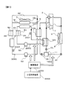
図1は、本発明による熱サイクルシステムを電気自動車の冷却空調システムに適用した場合の、冷却空調システムの概略構成を示す図である。図1に示す冷却空調システムは、車室内の空気状態を調整する空調システムとしての冷凍サイクル回路1000および空調用回路2000と、モータ、インバータ、走行駆動用バッテリおよびギアボックスなど、発熱を伴う温調対象機器16の温度を調整する温調システムとしての冷却用回路3000とを備えている。冷凍サイクル回路1000,空調用回路2000および冷却用回路3000を含む冷却空調システムは、制御装置4000により制御される。なお、制御装置4000には、車両側の上位制御装置5000から制御に必要な情報(例えば、モータトルク要求情報など)が入力される。
-First embodiment-
(Description of cooling air conditioning system)
FIG. 1 is a diagram showing a schematic configuration of a cooling air-conditioning system when the heat cycle system according to the present invention is applied to a cooling air-conditioning system for an electric vehicle. The cooling air-conditioning system shown in FIG. 1 includes a refrigeration cycle circuit 1000 and an air-conditioning circuit 2000 as an air-conditioning system that adjusts the air condition in the passenger compartment, and a temperature control with heat generation such as a motor, an inverter, a travel drive battery, and a gear box. And a cooling circuit 3000 as a temperature control system for adjusting the temperature of the target device 16. The cooling air conditioning system including the refrigeration cycle circuit 1000, the air conditioning circuit 2000, and the cooling circuit 3000 is controlled by the control device 4000. The control device 4000 receives information (for example, motor torque request information) necessary for control from the host-side control device 5000 on the vehicle side.

冷凍サイクル回路1000には冷媒が充填されている。冷媒としては、例えば、エアコン用冷媒として知られているR134aが用いられる。また、空調用回路2000には空調用熱移動媒体が循環され、冷却用回路3000には冷却用熱移動媒体が循環される。空調用熱移動媒体および冷却用熱移動媒体には、例えばクーラントが用いられる。   The refrigeration cycle circuit 1000 is filled with a refrigerant. As the refrigerant, for example, R134a known as a refrigerant for air conditioners is used. In addition, an air conditioning heat transfer medium is circulated in the air conditioning circuit 2000, and a cooling heat transfer medium is circulated in the cooling circuit 3000. For example, a coolant is used for the heat transfer medium for air conditioning and the heat transfer medium for cooling.

冷凍サイクル回路1000と空調用回路2000との間には空調用熱交換器10Aが設けられ、冷凍サイクル回路1000と冷却用回路3000との間には冷却用熱交換器10Bが設けられている。空調用熱交換器10Aにおいては、冷凍サイクル回路1000に充填された冷媒と空調用回路2000を循環する空調用熱移動媒体との間の熱交換が行われる。同様に、冷却用熱交換器10Bでは、冷凍サイクル回路1000に充填された冷媒と冷却用回路3000を循環する冷却用熱移動媒体との間で熱交換が行われる。   An air conditioning heat exchanger 10A is provided between the refrigeration cycle circuit 1000 and the air conditioning circuit 2000, and a cooling heat exchanger 10B is provided between the refrigeration cycle circuit 1000 and the cooling circuit 3000. In the air conditioner heat exchanger 10A, heat exchange is performed between the refrigerant charged in the refrigeration cycle circuit 1000 and the air conditioning heat transfer medium circulating in the air conditioning circuit 2000. Similarly, in the cooling heat exchanger 10B, heat is exchanged between the refrigerant charged in the refrigeration cycle circuit 1000 and the cooling heat transfer medium circulating in the cooling circuit 3000.

冷凍サイクル回路1000には、冷媒を圧縮する圧縮機1、冷媒と外気との熱交換を行う室外熱交換器9および上述した空調用熱交換器10Aが環状に接続されている。また、室外熱交換器9には外気送風用の室外ファン6が備えられている。圧縮機1の吸込配管12と吐出配管13との間には、四方弁3が設けられている。四方弁3の弁状態を切り替えることにより、吸込配管12および吐出配管13のいずれか一方を室外熱交換器9に接続し、他方を空調用熱交換器10Aに接続することができる。   The refrigeration cycle circuit 1000 is connected to the compressor 1 that compresses the refrigerant, the outdoor heat exchanger 9 that performs heat exchange between the refrigerant and the outside air, and the above-described heat exchanger 10A for air conditioning. The outdoor heat exchanger 9 is provided with an outdoor fan 6 for blowing outside air. A four-way valve 3 is provided between the suction pipe 12 and the discharge pipe 13 of the compressor 1. By switching the valve state of the four-way valve 3, one of the suction pipe 12 and the discharge pipe 13 can be connected to the outdoor heat exchanger 9, and the other can be connected to the air conditioner heat exchanger 10A.

図1は冷房運転時の四方弁3の弁状態を示しており、吐出配管13と室外熱交換器9とを接続すると共に、吸込配管12と空調用熱交換器10Aとを接続している。一方、後述する暖房運転や暖房冷却運転時には、四方弁3は、吐出配管13と空調用熱交換器10Aとを接続すると共に、吸込配管12と室外熱交換器9とを接続するように切り換えられる。   FIG. 1 shows the valve state of the four-way valve 3 during the cooling operation. The discharge pipe 13 and the outdoor heat exchanger 9 are connected, and the suction pipe 12 and the air conditioning heat exchanger 10A are connected. On the other hand, at the time of heating operation or heating cooling operation described later, the four-way valve 3 is switched so as to connect the discharge pipe 13 and the air conditioner heat exchanger 10A and connect the suction pipe 12 and the outdoor heat exchanger 9. .

室外熱交換器9と空調用熱交換器10Aとの間にはレシーバ11が設けられている。冷媒経路はレシーバ11において2つに分岐しており、一方は上述した空調用熱交換器10Aが設けられた冷媒経路であって、他方は冷却用熱交換器10Bが設けられた冷媒経路である。分岐した二つの冷媒経路は、圧縮機1の吸込配管12において合流して一つになる。2A〜2Cは冷媒の流量を制御するための流量制御弁であって、流量制御弁2Aは空調用熱交換器10Aを流れる冷媒の流量を制御し、流量制御弁2Bは冷却用熱交換器10Bを流れる冷媒の流量を制御し、流量制御弁2Cは室外熱交換器9を流れる冷媒の流量を制御する。 A receiver 11 is provided between the outdoor heat exchanger 9 and the air conditioner heat exchanger 10A. Refrigerant path branches into two at the receiver 11, one is a refrigerant path for the air-conditioning heat exchanger 10A described above is provided, the other is the refrigerant passage of the cooling heat exchanger 10B is provided . The two refrigerant paths branched are merged into one in the suction pipe 12 of the compressor 1. 2A to 2C are flow rate control valves for controlling the flow rate of the refrigerant, the flow rate control valve 2A controls the flow rate of the refrigerant flowing through the air conditioner heat exchanger 10A, and the flow rate control valve 2B is the heat exchanger 10B for cooling. The flow rate control valve 2C controls the flow rate of the refrigerant flowing through the outdoor heat exchanger 9.

空調用回路2000には、空調側室内熱交換器15A、空調用熱移動媒体を貯留するための空調用容積可変タンク8A、空調用熱移動媒体を循環させるための空調用循環ポンプ5Aおよび空調用熱交換器10A、が順に環状に接続されている。空調側室内熱交換器15Aには、車室内へ空気を送風する室内ファン7が備えられている。空調側熱交換器15Aにおいては、空調用熱移動媒体と室内ファン7によって車室内へ送風される空気との熱交換が行われる。2001は空調用回路2000を流れる熱移動媒体の温度を検出する温度センサであり、検出結果は制御装置4000に入力される。   The air conditioning circuit 2000 includes an air conditioning indoor heat exchanger 15A, an air conditioning volume variable tank 8A for storing an air conditioning heat transfer medium, an air conditioning circulation pump 5A for circulating the air conditioning heat transfer medium, and an air conditioning The heat exchanger 10A is connected in an annular shape in order. The air conditioning side indoor heat exchanger 15A is provided with an indoor fan 7 for blowing air into the vehicle interior. In the air conditioning side heat exchanger 15A, heat exchange between the heat transfer medium for air conditioning and the air blown into the vehicle interior by the indoor fan 7 is performed. Reference numeral 2001 denotes a temperature sensor that detects the temperature of the heat transfer medium flowing through the air conditioning circuit 2000, and the detection result is input to the control device 4000.

冷却用回路3000には、冷却側室内熱交換器15B、冷却用熱移動媒体を貯留するための冷却用容積可変タンク8B、温調対象機器16、冷却用熱移動媒体を循環させるための冷却用循環ポンプ5Bおよび冷却用熱交換器10Bが順に環状に接続されている。本実施形態では、温調対象機器16として、モータ、インバータ、バッテリおよびギアボックスがある。上述した室内ファン7は図示下側から上側へと送風し、送風方向に対して空調側室内熱交換器15Aの下流側に冷却側室内熱交換器15Bが配設されている。そのため、空調側室内熱交換器15Aから流出された空気は、冷却側室内熱交換器15Bにおいて冷却用熱移動媒体と熱交換を行った後に車室内へ吹き出される。   The cooling circuit 3000 includes a cooling-side indoor heat exchanger 15B, a cooling volume variable tank 8B for storing the cooling heat transfer medium, a temperature control target device 16, and a cooling for circulating the cooling heat transfer medium. Circulation pump 5B and cooling heat exchanger 10B are connected in an annular shape in order. In the present embodiment, the temperature control target device 16 includes a motor, an inverter, a battery, and a gear box. The indoor fan 7 described above blows from the lower side to the upper side in the figure, and a cooling side indoor heat exchanger 15B is disposed downstream of the air conditioning side indoor heat exchanger 15A in the blowing direction. Therefore, the air that has flowed out of the air-conditioning side indoor heat exchanger 15A is blown into the vehicle interior after performing heat exchange with the cooling heat transfer medium in the cooling-side indoor heat exchanger 15B.

また、冷却用回路3000には、主回路19に設けられた室内熱交換器15Bをバイパスするバイパス回路20が設けられている。バイパス回路20の入口には三方弁4が設けられている。この三方弁4を切り替えることにより、冷却用熱移動媒体が流れる経路として、主回路19またはバイパス回路20のいずれかに選択することができる。3001は冷却用回路3000を流れる熱移動媒体の温度を検出する温度センサであり、検出結果は制御装置4000に入力される。   The cooling circuit 3000 is provided with a bypass circuit 20 that bypasses the indoor heat exchanger 15B provided in the main circuit 19. A three-way valve 4 is provided at the inlet of the bypass circuit 20. By switching the three-way valve 4, either the main circuit 19 or the bypass circuit 20 can be selected as a path through which the cooling heat transfer medium flows. Reference numeral 3001 denotes a temperature sensor that detects the temperature of the heat transfer medium flowing through the cooling circuit 3000, and the detection result is input to the control device 4000.

空調用容積可変タンク8Aは、空調用回路2000を循環する空調用熱移動媒体の容積を変化させることができる。同様に冷却用容積可変タンク8Bは、冷却用回路3000を循環する冷却用熱移動媒体の容積を変化させることができる。なお、本実施の形態では、空調用容積可変タンク8Aおよび冷却用容積可変タンク8Bの両方が設けられているが、どちらか一方のみが設けられていても良い。   The air conditioning volume variable tank 8 </ b> A can change the volume of the air conditioning heat transfer medium circulating in the air conditioning circuit 2000. Similarly, the cooling volume variable tank 8B can change the volume of the cooling heat transfer medium circulating in the cooling circuit 3000. In this embodiment, both the air conditioning volume variable tank 8A and the cooling volume variable tank 8B are provided, but only one of them may be provided.

(容積可変タンクの構成)
図1に示した空調用容積可変タンク8Aと冷却用容積可変タンク8Bとは同一構造を有しており、図2はそれらに用いられる容積可変タンク8の概略構成を示したものである。容積可変タンク8は、タンク内空間を第1空間23と第2空間24との2つに分離する断熱パーティション25を備えている。第1空間23には流入口28および流出口29が設けられており、これらを循環回路に接続することによって、第1空間23は循環回路の一部を構成することになる。
(Configuration of variable volume tank)
The air-conditioning volume variable tank 8A and the cooling volume variable tank 8B shown in FIG. 1 have the same structure, and FIG. 2 shows a schematic configuration of the volume variable tank 8 used for them. The variable volume tank 8 includes a heat insulating partition 25 that separates the tank internal space into a first space 23 and a second space 24. The first space 23 is provided with an inlet 28 and an outlet 29. By connecting these to the circulation circuit, the first space 23 constitutes a part of the circulation circuit.

容積可変タンク8を空調用容積可変タンク8Aとして用いる場合には、流入口28を空調側室内熱交換器15Aに接続し、流出口29を空調用循環ポンプ5Aに接続することで、第1空間23は空調用回路2000の一部を構成することになる。同様に、容積可変タンク8を冷却用容積可変タンク8Bとして用いる場合には、流入口28を冷却側室内熱交換器15Bに接続し、流出口29を冷却用循環ポンプ5Bに接続することで、第1空間23は冷却用回路3000の一部を構成することになる。   When the variable volume tank 8 is used as the air conditioning volume variable tank 8A, the inlet 28 is connected to the air conditioning indoor heat exchanger 15A, and the outlet 29 is connected to the air conditioning circulation pump 5A. 23 constitutes a part of the air conditioning circuit 2000. Similarly, when the variable volume tank 8 is used as the cooling variable volume tank 8B, by connecting the inlet 28 to the cooling side indoor heat exchanger 15B and connecting the outlet 29 to the cooling circulation pump 5B, The first space 23 constitutes a part of the cooling circuit 3000.

断熱パーティション25には第1空間23と第2空間24とを連通する連通孔26が設けられており、第2空間24にも熱移動媒体が満たされている。断熱パーティション25は、アクチュエータ801の駆動軸27に固定されている。アクチュエータ801で駆動軸27を上下動させて断熱パーティション25を矢印50a,50bの方向に移動させると、空間23,24の容積が変化し、連通孔26を通って熱移動媒体が第1空間23と第2空間24との間を移動する。すなわち、循環回路(空調用回路2000または冷却用回路3000)内の熱移動媒体の容積が増加する。第1空間23の容積変化は、断熱パーティション25の移動量を検知することにより検出することができる。 The heat insulating partition 25 is provided with a communication hole 26 that communicates the first space 23 and the second space 24, and the second space 24 is also filled with the heat transfer medium. The heat insulating partition 25 is fixed to the drive shaft 27 of the actuator 801. When the drive shaft 27 is moved up and down by the actuator 801 and the heat insulating partition 25 is moved in the directions of the arrows 50 a and 50 b, the volumes of the spaces 23 and 24 change, and the heat transfer medium passes through the communication holes 26 and the first movement space 23. And the second space 24. That is, the volume of the heat transfer medium in the circulation circuit (the air conditioning circuit 2000 or the cooling circuit 3000) increases. The volume change of the first space 23 can be detected by detecting the movement amount of the heat insulating partition 25.

なお、第1空間23と第2空間24とは連通孔26により連通しているが、断熱パーティション25が停止している時は、連通孔26を介した熱移動媒体の移動は非常に小さく、第2空間24は循環回路を構成しないと考えて良い。すなわち、断熱パーティション25を移動したときだけ、熱移動媒体が連通孔26内を移動する。また、断熱パーティション25は熱伝導率の低い断熱材料(例えば、合成樹脂など)で構成されており、第1空間23内の熱移動媒体と第2空間24内の熱移動媒体との熱交換は、低く抑えられている。なお、断熱パーティション25は、全体を断熱材料で形成しても良いし、一部(例えば、熱移動媒体に接触する表面部分)を断熱材料で形成しても良い。   The first space 23 and the second space 24 communicate with each other through the communication hole 26. However, when the heat insulating partition 25 is stopped, the movement of the heat transfer medium through the communication hole 26 is very small. It may be considered that the second space 24 does not constitute a circulation circuit. That is, the heat transfer medium moves in the communication hole 26 only when the heat insulating partition 25 is moved. The heat insulating partition 25 is made of a heat insulating material (for example, synthetic resin) having a low thermal conductivity, and heat exchange between the heat transfer medium in the first space 23 and the heat transfer medium in the second space 24 is performed. , Is kept low. Note that the heat insulating partition 25 may be entirely formed of a heat insulating material, or a part (for example, a surface portion in contact with the heat transfer medium) may be formed of a heat insulating material.

このように容積可変タンク8の第1空間23の容積を変化させることにより、循環回路を循環する熱移動媒体の熱容量を可変にすることができる。第1空間23の容積を小さくすると循環回路を循環する熱移動媒体の総量が減って熱容量が小さくなるので、熱エネルギーの流出入量に対する熱移動媒体の温度変化速度(すなわち温度応答速度)はより速くなる。逆に、第1空間23の容積を大きくすると循環回路を循環する熱移動媒体の総量が増加して熱容量が大きくなるので、温度変化速度はより遅くなる。すなわち、容積可変タンク8の第1空間23の容積を変化させることで、熱移動媒体を状況に応じた望ましい温度応答速度にすることができる。   Thus, by changing the volume of the first space 23 of the variable volume tank 8, the heat capacity of the heat transfer medium circulating in the circulation circuit can be made variable. When the volume of the first space 23 is reduced, the total amount of the heat transfer medium circulating in the circulation circuit is reduced and the heat capacity is reduced. Therefore, the temperature change rate of the heat transfer medium (that is, the temperature response speed) with respect to the amount of heat energy flowing in and out is further increased. Get faster. On the contrary, when the volume of the first space 23 is increased, the total amount of the heat transfer medium circulating in the circulation circuit is increased and the heat capacity is increased, so that the temperature change rate becomes slower. That is, by changing the volume of the first space 23 of the variable volume tank 8, the heat transfer medium can be set to a desired temperature response speed according to the situation.

断熱パーティション25に設けられた連通孔26は、図14に示すように開閉自在であってもよい。図14(a)に示す容積可変タンク8では、連通孔26に弁体802、803が設けられている。この構成の場合、断熱パーティション25を下方(50a方向)に移動すると弁体802が開いて、破線矢印のように第1空間23から第2空間24へ熱移動媒体が移動する。逆に、断熱パーティション25を上方(50b方向)に移動すると弁体803が開いて、破線矢印のように第2空間24から第1空間23へ熱移動媒体が移動する。 The communication hole 26 provided in the heat insulating partition 25 may be freely opened and closed as shown in FIG. In the variable volume tank 8 shown in FIG. 14A, valve bodies 802 and 803 are provided in the communication hole 26. In this configuration, when the heat insulating partition 25 is moved downward (in the direction of 50a), the valve body 802 is opened, and the heat transfer medium is moved from the first space 23 to the second space 24 as indicated by broken line arrows. Conversely, when the heat insulating partition 25 is moved upward (in the 50b direction), the valve body 803 is opened, and the heat transfer medium is moved from the second space 24 to the first space 23 as indicated by a broken line arrow.

断熱パーティション25が停止しているときには弁体802,803は閉じ、熱移動媒体は遮断される。そのため、第1空間23内と第2空間24内の間での熱移動媒体の熱交換量を減らすことができる。これにより熱移動媒体の温度応答速度を調節しやすくなる。   When the heat insulating partition 25 is stopped, the valve bodies 802 and 803 are closed, and the heat transfer medium is shut off. Therefore, the heat exchange amount of the heat transfer medium between the first space 23 and the second space 24 can be reduced. This makes it easier to adjust the temperature response speed of the heat transfer medium.

図14(b)は断熱パーティション25に連通孔26を設ける代わりに、第1空間23と第2空間24とを連通刷る配管804を設けた。この場合にも、配管804を一対設けて、一方に弁体802を、他方に弁体803を設けるような構成としても良い。   In FIG. 14B, instead of providing the communication hole 26 in the heat insulating partition 25, a pipe 804 that communicates the first space 23 and the second space 24 is provided. Also in this case, a configuration in which a pair of pipes 804 are provided, a valve body 802 is provided on one side and a valve body 803 is provided on the other side may be employed.

次に、図1に示した冷却空調システムの運転動作について説明する。本実施形態では、冷却用循環ポンプ5Bを稼働させて温調対象機器16の温度調整を行う。その他の機器の動作は、空調負荷や温調対象機器16からの発熱量に応じて変化させる。以下では、冷房運転、除湿運転,暖房運転および暖房冷却運転について説明する。   Next, the operation of the cooling air conditioning system shown in FIG. 1 will be described. In the present embodiment, the cooling circulation pump 5B is operated to adjust the temperature of the temperature adjustment target device 16. The operation of other devices is changed according to the air conditioning load and the amount of heat generated from the temperature control target device 16. Hereinafter, the cooling operation, the dehumidifying operation, the heating operation, and the heating / cooling operation will be described.

(冷房運転)
冷房運転とは、室外熱交換器9を凝縮器、空調用熱交換10Aと冷却用熱交換10Bを蒸発器として用いて、空調用回路2000および冷却用回路3000から冷凍サイクル回路1000へと熱を移動させる運転モードである。冷房運転の場合には、冷凍サイクル回路1000に設けられた四方弁3は、図1で示すような弁の切り換え状態とする。すなわち、圧縮機1の吐出配管13は室外熱交換器9に接続し、圧縮機1の吸込配管12は空調用熱交換器10Aおよび冷却用熱交換器10Bに接続する。
(Cooling operation)
The cooling operation, the outdoor heat exchanger 9 condenser, and the air-conditioning heat exchanger 10A the cooling heat exchanger 10B is used as an evaporator, and the air-conditioning circuitry 2000 and the cooling circuit 3000 to the refrigeration cycle circuit 1000 This is an operation mode in which heat is transferred. In the cooling operation, the four-way valve 3 provided in the refrigeration cycle circuit 1000 is in a valve switching state as shown in FIG. That is, the discharge pipe 13 of the compressor 1 is connected to the outdoor heat exchanger 9, and the suction pipe 12 of the compressor 1 is connected to the air conditioner heat exchanger 10A and the cooling heat exchanger 10B.

圧縮機1で圧縮された冷媒は、室外熱交換器9で放熱することによって液化した後、空調用熱交換器10Aへ流れる冷媒と冷却用熱交換器10Bへ流れる冷媒とに分岐される。空調用熱交換器10Aに流入する冷媒は、空調側流量制御弁2Aで減圧されて低温・低圧となった後、空調用熱交換器10Aにおいて空調用回路2000の空調用熱移動媒体から吸熱することによって蒸発し、四方弁3を通って圧縮機1へ戻る。一方、冷却用熱交換器10Bへ流入した冷媒は、冷却側流量制御弁2Bで減圧されて低温・低圧となり、冷却用熱交換器10Bにおいて冷却用回路3000の冷却用熱移動媒体から吸熱することによって蒸発し、圧縮機1へと戻る。   The refrigerant compressed by the compressor 1 is liquefied by radiating heat from the outdoor heat exchanger 9, and then branched into a refrigerant flowing to the air conditioning heat exchanger 10A and a refrigerant flowing to the cooling heat exchanger 10B. The refrigerant flowing into the air conditioning heat exchanger 10A is depressurized by the air conditioning side flow control valve 2A to become low temperature and low pressure, and then absorbs heat from the air conditioning heat transfer medium of the air conditioning circuit 2000 in the air conditioning heat exchanger 10A. And then returns to the compressor 1 through the four-way valve 3. On the other hand, the refrigerant flowing into the cooling heat exchanger 10B is depressurized by the cooling side flow control valve 2B to become low temperature and low pressure, and absorbs heat from the cooling heat transfer medium of the cooling circuit 3000 in the cooling heat exchanger 10B. Evaporates and returns to the compressor 1.

空調用回路2000においては、空調用循環ポンプ5Aを駆動することで、空調用熱交換器10Aで冷却された空調用熱移動媒体が空調側室内熱交換器15Aに供給される。そして、室内ファン7を駆動することで、空調側室内熱交換器15Aで熱交換して冷却された空気が車室内へ吹き出される。また、冷却用回路3000では、冷却用循環ポンプ5Bにより循環される冷却用熱移動媒体は、温調対象機器16の発熱により加熱されるとともに、冷却用熱交換10Bにおいて冷凍サイクル回路1000側の冷媒と熱交換することにより冷却される。 In the air conditioning circuit 2000, by driving the air conditioning circulation pump 5A, the air conditioning heat transfer medium cooled by the air conditioning heat exchanger 10A is supplied to the air conditioning indoor heat exchanger 15A. Then, by driving the indoor fan 7, air cooled by heat exchange in the air conditioning side indoor heat exchanger 15A is blown out into the vehicle interior. Moreover, the cooling circuit 3000, cooling heat-transfer medium which is circulated by the circulation pump for cooling 5B, along with being heated by the heating temperature control target device 16, the refrigerating cycle circuit 1000 side in the cooling heat exchanger 10B It is cooled by exchanging heat with the refrigerant.

このように、冷房運転モードでは、空調用熱交換器10Aおよび冷却用熱交換器10Bの両方を蒸発器として利用することで、車室内の冷房と温調対象機器16の冷却とを同時に実現することができる。また、図1に示す構成では、空調用熱交換器10Aと冷却用熱交換器10Bとを圧縮機1の吸込配管12に対して並列に接続するとともに、それぞれの冷媒回路に空調側流量制御弁2A、冷却側流量制御弁2Bを設けているので、空調用熱交換器10Aおよび冷却用熱交換器10Bへ流れる冷媒の流量を、それぞれ任意に変えることができる。   As described above, in the cooling operation mode, both the air conditioning heat exchanger 10A and the cooling heat exchanger 10B are used as evaporators, thereby simultaneously cooling the passenger compartment and cooling the temperature control target device 16. be able to. 1, the air conditioning heat exchanger 10A and the cooling heat exchanger 10B are connected in parallel to the suction pipe 12 of the compressor 1, and the air conditioning side flow control valve is connected to each refrigerant circuit. Since 2A and the cooling side flow control valve 2B are provided, the flow rate of the refrigerant flowing to the air conditioning heat exchanger 10A and the cooling heat exchanger 10B can be arbitrarily changed.

その結果、冷却用熱移動媒体の温度と空調用熱移動媒体の温度とを、個別に所望の温度に制御することができる。例えば、冷房を行うために空調用熱移動媒体の温度を十分に下げた場合であっても、冷却用熱交換器10Bへ流れる冷媒流量を抑制することで、温調対象機器16が接続された冷却用熱移動媒体の温度を高めに保つことができる。なお、冷却用熱移動媒体の温度を制御するためには、冷却側流量制御弁2Bの開度を制御すれば良く、簡易的には冷却用熱移動媒体の温度が高い場合に開度を開き、温度が低い場合には開度を絞るように制御すれば良い。   As a result, the temperature of the cooling heat transfer medium and the temperature of the air conditioning heat transfer medium can be individually controlled to desired temperatures. For example, even when the temperature of the air-conditioning heat transfer medium is sufficiently lowered for cooling, the temperature adjustment target device 16 is connected by suppressing the flow rate of the refrigerant flowing to the cooling heat exchanger 10B. The temperature of the cooling heat transfer medium can be kept high. In order to control the temperature of the cooling heat transfer medium, it is only necessary to control the opening degree of the cooling-side flow rate control valve 2B, which is simply opened when the temperature of the cooling heat transfer medium is high. When the temperature is low, the opening degree may be controlled.

なお、冷凍サイクル回路1000の温調能力を調整するためには、圧縮機1の回転数を制御して、空調用熱移動媒体の温度が所望の温度となるように制御する。冷房負荷が大きいと判断した場合には、空調用熱移動媒体の制御目標温度を低くし、冷房負荷が小さいと判断した場合には、空調用熱移動媒体の制御目標温度を高くすることによって、負荷に応じた空調能力の制御が可能となる。   In addition, in order to adjust the temperature control capability of the refrigeration cycle circuit 1000, the rotation speed of the compressor 1 is controlled so that the temperature of the heat transfer medium for air conditioning becomes a desired temperature. When it is determined that the cooling load is large, the control target temperature of the heat transfer medium for air conditioning is lowered, and when it is determined that the cooling load is small, the control target temperature of the heat transfer medium for air conditioning is increased, It becomes possible to control the air conditioning capacity according to the load.

また、冷房負荷がなく、冷却回路3000に設けられた温調対象機器16の冷却のみが必要な場合には、空調用循環ポンプ5A、および室内ファン7を停止するとともに、空調側流量制御弁2Aを閉じる。そして、冷却側流量制御弁2Bの開度を調整することによって、冷却用熱交換10Bのみを蒸発器と利用すれば良い。このように制御することで、冷却回路3000の冷却用熱移動媒体の冷却が可能となるので、温調対象機器16の冷却ができる。この場合、圧縮機1の回転数は、冷却用熱移動媒体の温度が目標温度となるように制御される。また、空調用循環ポンプ5Aの回転数を制御することで、熱交換量を変化させてもよい。 Further, there is no cooling load, when only cooling of the cooling circuit 3000 temperature control target device 16 provided is necessary, the air-conditioning circulation pump 5A, and stops the indoor fan 7, the air-conditioning-side flow rate control valve Close 2A. Then, by adjusting the opening of the cooling-side flow rate control valve 2B, only it may be utilized as an evaporator for cooling the heat exchanger 10B. By controlling in this manner, the cooling of the cooling heat-transfer medium of the cooling circuit 3000 is enabled, it is cooled temperature control target device 16. In this case, the rotation speed of the compressor 1 is controlled such that the temperature of the cooling heat transfer medium becomes the target temperature. Further, the amount of heat exchange may be changed by controlling the rotation speed of the air-conditioning circulation pump 5A.

(除湿運転)
図3は、除湿運転時の四方弁3の弁状態を示したものである。なお、制御装置4000および上位制御装置5000は図示を省略した。除湿運転では、冷却用回路3000に設けられた三方弁4の弁状態を制御して、温度の高い冷却用熱移動媒体を冷却側室内熱交換器15Bが設けられた主回路19へ流すようにする。このように、温度の高い冷却用熱移動媒体を冷却側室内熱交換器15Bに導入することで、空調側室内熱交換器15Bで冷却・除湿された空気が、冷却側室内熱交換器15Bによって加熱されてから車室内へ吹き出される、いわゆる再熱除湿運転が可能となる。除湿運転では、車室内へ供給される空気は相対湿度が低くなるため、車室空間の快適性を向上できる。
(Dehumidifying operation)
FIG. 3 shows the valve state of the four-way valve 3 during the dehumidifying operation. The control device 4000 and the host control device 5000 are not shown. In the dehumidifying operation, the valve state of the three-way valve 4 provided in the cooling circuit 3000 is controlled so that the high-temperature cooling heat transfer medium flows to the main circuit 19 provided with the cooling-side indoor heat exchanger 15B. To do. In this way, by introducing a high-temperature cooling heat transfer medium to the cooling-side indoor heat exchanger 15B, the air cooled and dehumidified by the air-conditioning-side indoor heat exchanger 15B is cooled by the cooling-side indoor heat exchanger 15B. A so-called reheat dehumidification operation in which the vehicle is heated and then blown out into the passenger compartment becomes possible. In the dehumidifying operation, since the relative humidity of the air supplied to the vehicle interior is low, the comfort of the vehicle interior space can be improved.

なお、再熱器として利用される冷却側室内熱交換器15Bの熱源は、温調対象機器16が発生するいわゆる排熱である。そのため、再熱用にヒータ等を用いる場合とは異なり、新たにエネルギーを投入する必要がないので、消費電力を増大させることなく車室内の快適性を向上させることが可能になる。   Note that the heat source of the cooling-side indoor heat exchanger 15B used as a reheater is so-called exhaust heat generated by the temperature adjustment target device 16. Therefore, unlike the case of using a heater or the like for reheating, it is not necessary to input new energy, so that it is possible to improve the comfort in the vehicle interior without increasing the power consumption.

再熱量は主回路19へ流れる冷却用熱移動媒体の温度と流量によって変化するので、冷却用熱交換器10Bの交換熱量や、主回路19へ流れる冷却用熱移動媒体の流量を変えることによって、再熱量を制御することができる。冷却用熱交換器10Bの熱交換量を可変とするためには、冷却側流量制御弁2Bの開度を制御して、冷却用熱交換10Bへ流れる冷媒流量を制御すれば良く、冷却が不要な場合には冷却側流量制御弁2Bの開度を全閉とすれば良い。 Since the amount of reheat varies depending on the temperature and flow rate of the cooling heat transfer medium flowing to the main circuit 19, by changing the exchange heat amount of the cooling heat exchanger 10B and the flow rate of the cooling heat transfer medium flowing to the main circuit 19, The amount of reheat can be controlled. Heat exchange of the cooling heat exchanger 10B to to variable controls the opening of the cooling-side flow rate control valve 2B, may be controlled flow rate of the refrigerant flowing into the cooling heat exchanger 10B, cooling If unnecessary, the opening of the cooling side flow control valve 2B may be fully closed.

(暖房運転)
図4は、暖房運転時の四方弁3の弁状態を示す図である。なお、制御装置4000および上位制御装置5000は図示を省略した。暖房運転時には、暖房負荷に応じた2つの運転モードがある。一つ目の運転モードは、暖房負荷が小さい時の放熱運転モードであり、温調対象機器16からの排熱を暖房に利用することで、冷凍サイクル回路1000は暖房に利用しない。二つ目の運転モードは、温調対象機器16の排熱だけでは必要な暖房負荷に満たない場合の運転モードであって、温調対象機器16の排熱に加えて冷凍サイクル回路1000を併用する暖房放熱運転モードである。
(Heating operation)
FIG. 4 is a diagram illustrating a valve state of the four-way valve 3 during the heating operation. The control device 4000 and the host control device 5000 are not shown. During the heating operation, there are two operation modes depending on the heating load. The first operation mode is a heat radiation operation mode when the heating load is small, and the refrigeration cycle circuit 1000 is not used for heating by using the exhaust heat from the temperature control target device 16 for heating. The second operation mode is an operation mode when the exhaust heat of the temperature control target device 16 alone does not satisfy the required heating load, and in addition to the exhaust heat of the temperature control target device 16, the refrigeration cycle circuit 1000 is used in combination. It is a heating heat radiation operation mode.

一つ目の放熱運転モードでは、冷却用循環ポンプ5Bと室内ファン7を起動し、かつ三方弁4の弁状態を制御して冷却側室内熱交換器15Bに冷却用熱移動媒体を導入する。温調対象機器16によって加熱された冷却用熱移動媒体は、冷却側室内熱交換器15Bにおいて室内吹出し空気へ放熱することによって冷却され、室内吹き出し空気が加熱されることになる。このように温調対象機器16からの排熱を暖房に利用することで、エネルギー消費を抑えて空調を行うことができる。   In the first heat radiation operation mode, the cooling circulation pump 5B and the indoor fan 7 are started, and the valve state of the three-way valve 4 is controlled to introduce the cooling heat transfer medium into the cooling-side indoor heat exchanger 15B. The cooling heat transfer medium heated by the temperature control target device 16 is cooled by radiating heat to the indoor blowing air in the cooling side indoor heat exchanger 15B, and the indoor blowing air is heated. Thus, by using the exhaust heat from the temperature control target device 16 for heating, it is possible to perform air conditioning while suppressing energy consumption.

二つ目の暖房放熱運転モードの場合、冷凍サイクル回路1000に設けられた四方弁3を図4で示す弁状態に切り換えて、圧縮機1の吐出配管13を空調用熱交換器10Aに接続するとともに、吸込配管12を室外熱交換器9に接続する。すなわち、空調用熱交換器10Aを凝縮器、室外熱交換器9を蒸発器とするサイクルが形成される。   In the case of the second heating / heat radiation operation mode, the four-way valve 3 provided in the refrigeration cycle circuit 1000 is switched to the valve state shown in FIG. 4, and the discharge pipe 13 of the compressor 1 is connected to the air conditioner heat exchanger 10A. At the same time, the suction pipe 12 is connected to the outdoor heat exchanger 9. That is, a cycle is formed in which the air conditioner heat exchanger 10A is a condenser and the outdoor heat exchanger 9 is an evaporator.

圧縮機1で圧縮された冷媒は、空調用熱交換器10Aで空調用熱移動媒体へ放熱することによって凝縮液化する。その後、流量制御弁2Cで減圧された後、室外熱交換器9において室外空気との熱交換によって蒸発・ガス化して圧縮機1へと戻る。なお、この運転モードでは、流量制御弁2Aは全開、流量制御弁2Bは全閉とし、冷却用熱交換器10Bは利用しない。   The refrigerant compressed by the compressor 1 is condensed and liquefied by releasing heat to the air-conditioning heat transfer medium by the air-conditioning heat exchanger 10A. Thereafter, the pressure is reduced by the flow rate control valve 2 </ b> C, and then the outdoor heat exchanger 9 is evaporated and gasified by heat exchange with outdoor air, and returns to the compressor 1. In this operation mode, the flow control valve 2A is fully opened, the flow control valve 2B is fully closed, and the cooling heat exchanger 10B is not used.

空調用熱移動媒体は、空調用循環ポンプ5Aを起動することにより空調用回路2000を循環され、空調用熱交換10Aで冷媒の凝縮熱をもらって加熱される。その加熱された空調用熱移動媒体は空調側室内熱交換器15Aへ流入し、空調側室内熱交換器15Aにおいて室内吹出し空気へ放熱する。空調側室内熱交換器15Aで加熱された空気は、空気の流れの下流側に配置された冷却側室内熱交換器15Bにおいて、温調対象機器16によって加熱された冷却用熱移動媒体から熱をもらい、さらに加熱されてから室内空間へ吹き出される。 The air-conditioning heat-transfer medium is circulated through the air-conditioning circuit 2000 by starting the air-conditioning circulation pump 5A, is heated got heat of condensation of the refrigerant in the air-conditioning heat exchanger 10A. The heated air-conditioning heat transfer medium flows into the air-conditioning side indoor heat exchanger 15A, and radiates heat to the indoor blowing air in the air-conditioning-side indoor heat exchanger 15A. The air heated by the air conditioning side indoor heat exchanger 15A is heated from the cooling heat transfer medium heated by the temperature control target device 16 in the cooling side indoor heat exchanger 15B disposed downstream of the air flow. After being heated, it is blown out into the indoor space.

このように室内吹出し空気は、冷凍サイクル回路1000によって加熱された後に、温調対象機器16の排熱でさらに加熱される構成となっている。そのため、空調側室内熱交換器15Aからの吹出し空気温度を、冷却側室内熱交換器15Bからの室内吹出し空気温度に対して低く保つことができる。すなわち、温調対象機器16からの排熱を暖房に利用することによって、エネルギー消費の少ない空調装置を構成することができる。   As described above, the indoor blown air is heated by the refrigeration cycle circuit 1000 and then heated by the exhaust heat of the temperature adjustment target device 16. Therefore, the temperature of the air blown from the air conditioning side indoor heat exchanger 15A can be kept lower than the temperature of the air blown from the cooling side indoor heat exchanger 15B. That is, an air conditioner with less energy consumption can be configured by using the exhaust heat from the temperature control target device 16 for heating.

また、冷凍サイクル回路1000の温調能力を制御することにより、温調対象機器16の発熱に応じて冷却用熱移動媒体の温度を制御することができる。温調対象機器16からの発熱量が増大した場合には、冷却用熱移動媒体の温度が上昇するので、冷凍サイクル回路1000の温調能力を抑制する。これによって空調側室内熱交換器15Aからの放熱量が抑制され、冷却側室内熱交換器15Bへ流入する空気の温度が低くなるので、冷却用熱移動媒体からの放熱量が増大し、冷却用熱移動媒体の温度上昇が抑制される。逆に、温調対象機器16からの発熱量が減少した場合には、冷却用熱移動媒体の温度が低下するので、冷凍サイクル回路1000の温調能力を増大させ、空調側室内熱交換器15Aから冷却側室内熱交換器15Bに流入する空気の温度を上げることで、冷却用熱移動媒体の温度低下を抑制する。   Further, by controlling the temperature adjustment capability of the refrigeration cycle circuit 1000, the temperature of the cooling heat transfer medium can be controlled in accordance with the heat generation of the temperature adjustment target device 16. When the heat generation amount from the temperature adjustment target device 16 increases, the temperature of the cooling heat transfer medium rises, so that the temperature adjustment capability of the refrigeration cycle circuit 1000 is suppressed. As a result, the amount of heat released from the air conditioning side indoor heat exchanger 15A is suppressed, and the temperature of the air flowing into the cooling side indoor heat exchanger 15B is lowered. The temperature rise of the heat transfer medium is suppressed. Conversely, when the amount of heat generated from the temperature control target device 16 decreases, the temperature of the cooling heat transfer medium decreases, so the temperature control capability of the refrigeration cycle circuit 1000 is increased, and the air conditioning side indoor heat exchanger 15A. The temperature of the cooling heat transfer medium is suppressed by increasing the temperature of the air flowing into the cooling-side indoor heat exchanger 15B from the inside.

なお冷凍サイクル回路1000の温調能力を制御するための具体例としては、圧縮機1の回転数を制御すれば良い。また、冷却用熱移動媒体の温度を所定の温度域に保つ制御は、温調対象機器16の温度が使用可能な温度域から外れるなどの不具合を回避するうえでも有効である。   In addition, what is necessary is just to control the rotation speed of the compressor 1 as a specific example for controlling the temperature control capability of the refrigerating cycle circuit 1000. Control for keeping the temperature of the cooling heat transfer medium in a predetermined temperature range is also effective in avoiding problems such as the temperature of the temperature adjustment target device 16 being out of the usable temperature range.

(暖房冷却運転)
図5は、暖房冷却運転の四方弁3の弁状態を説明する図である。なお、制御装置4000および上位制御装置5000は図示を省略した。暖房負荷が大きな場合には、上述したように冷却用熱移動媒体の目標温度を高く設定すれば良いが、温調対象機器16の仕様等により温度を上げることが困難な場合には、暖房能力を増大させることができなくなる。このような場合には、以下に説明する暖房冷却運転を行い、冷却用熱移動媒体の冷却と空調用熱移動媒体の加熱を同時に実現する。
(Heating / cooling operation)
FIG. 5 is a diagram illustrating the valve state of the four-way valve 3 in the heating / cooling operation. The control device 4000 and the host control device 5000 are not shown. When the heating load is large, the target temperature of the cooling heat transfer medium may be set high as described above. However, if it is difficult to increase the temperature due to the specifications of the temperature control target device 16 or the like, the heating capacity Cannot be increased. In such a case, the heating / cooling operation described below is performed to simultaneously cool the cooling heat transfer medium and heat the air conditioning heat transfer medium.

暖房冷却運転では、暖房放熱運転モードと同様に、空調用熱交換器10Aを凝縮器、室外熱交換器9を蒸発器とするサイクルを構成し、さらに流量制御弁2Bを開けて、冷却用熱交換器10Bを蒸発器として利用する。空調用熱交換器10Aで凝縮・液化した冷媒はレシーバ11内で分岐し、分岐した一方の冷媒は流量制御弁2Cで減圧された後、室外熱交換器9で蒸発して圧縮機1へ戻る。分岐した他方の冷媒は冷却側の流量制御弁2Bで減圧され、冷却用熱交換器10Bで冷却用熱移動媒体を冷却することによって蒸発・ガス化し、圧縮機1へと戻る。   In the heating / cooling operation, similarly to the heating / heat radiation operation mode, a cycle is formed in which the air-conditioning heat exchanger 10A is a condenser and the outdoor heat exchanger 9 is an evaporator, and the flow control valve 2B is opened to cool the cooling heat. The exchanger 10B is used as an evaporator. The refrigerant condensed and liquefied by the air conditioner heat exchanger 10A is branched in the receiver 11, and one of the branched refrigerants is decompressed by the flow control valve 2C, and then evaporated by the outdoor heat exchanger 9 to return to the compressor 1. . The other branched refrigerant is depressurized by the cooling-side flow control valve 2B, and is evaporated and gasified by cooling the cooling heat transfer medium by the cooling heat exchanger 10B, and returns to the compressor 1.

暖房冷却運転では、温調対象機器16からの排熱は、冷却用熱交換器10Bで冷凍サイクル回路1000の熱源として回収され、空調用熱交換器10Aから空調用回路2000を通って、空調側室内熱交換器15Aから車室内へ放熱される。このように、温調対象機器16の温度を抑制しながら温調対象機器16の排熱を回収して暖房に利用することが可能となっている。さらに、室外熱交換器9を用いて外気から吸熱することが可能となっているので、暖房能力を増大させることができる。   In the heating / cooling operation, the exhaust heat from the temperature adjustment target device 16 is recovered as a heat source of the refrigeration cycle circuit 1000 by the cooling heat exchanger 10B, and passes from the air conditioning heat exchanger 10A through the air conditioning circuit 2000 to the air conditioning side. Heat is radiated from the indoor heat exchanger 15A to the vehicle interior. As described above, the exhaust heat of the temperature adjustment target device 16 can be recovered and used for heating while suppressing the temperature of the temperature adjustment target device 16. Furthermore, since it is possible to absorb heat from the outside air using the outdoor heat exchanger 9, the heating capacity can be increased.

また、レシーバ11と室外熱交換器9との間に流量制御弁2Cを備える構成としたので、流量制御弁2Bと流量制御弁2Cの開度をそれぞれ制御することによって、冷却用熱移動媒体からの吸熱量と外気からの吸熱量を個別に制御することが可能である。なお、冷却用熱移動媒体の温度が、空調用熱移動媒体の温度よりも低くなると、空調側室内熱交換器15Aで加熱した空気を冷却側室内熱交換器15Bで冷却してしまうことになる。このような場合には、冷却用回路3000において三方弁4の弁状態を制御し、バイパス回路20を利用することで、冷却用熱交換器10Bで冷却された冷却用熱移動媒体によって、室内吹出し空気が冷却されることを防止できる。   Moreover, since it was set as the structure provided with the flow control valve 2C between the receiver 11 and the outdoor heat exchanger 9, from the heat transfer medium for cooling by controlling the opening degree of the flow control valve 2B and the flow control valve 2C, respectively. It is possible to individually control the amount of heat absorbed and the amount of heat absorbed from the outside air. When the temperature of the cooling heat transfer medium becomes lower than the temperature of the air conditioning heat transfer medium, the air heated by the air conditioning side indoor heat exchanger 15A is cooled by the cooling side indoor heat exchanger 15B. . In such a case, the valve state of the three-way valve 4 is controlled in the cooling circuit 3000, and the bypass circuit 20 is used so that the cooling heat transfer medium cooled by the cooling heat exchanger 10B causes the indoor blowout. It is possible to prevent the air from being cooled.

暖房冷却運転から暖房負荷が下がり、暖房放熱運転モードに移行する場合に、冷却用熱移動媒の温度が低いと吹出し温度が低い等の不具合が生じる可能性があるので、移行する前に冷却用熱移動媒体の温度を上げておくことが望ましい。冷却用熱移動媒体の温度は冷却用熱交換器10Bの熱交換量を可変とすることで制御することができるので、冷却側流量制御弁2Bの開度を制御すれば良い。なお、暖房冷却運転中も冷却用熱移動媒体の温度を高く保ち、空調用熱移動媒体の温度が冷却用熱移動媒体の温度よりも下がったことを検知した場合には、暖房負荷が下がったと判断することができるので、暖房冷却運転から暖房放熱運転モードへ移行することができる。   When the heating load drops from the heating / cooling operation and shifts to the heating / radiation operation mode, there is a possibility that problems such as low blowout temperature may occur if the temperature of the cooling heat transfer medium is low. It is desirable to raise the temperature of the heat transfer medium. Since the temperature of the cooling heat transfer medium can be controlled by making the heat exchange amount of the cooling heat exchanger 10B variable, the opening degree of the cooling side flow control valve 2B may be controlled. When the temperature of the heat transfer medium for cooling is kept high during the heating / cooling operation and the temperature of the heat transfer medium for air conditioning is detected to be lower than the temperature of the heat transfer medium for cooling, the heating load is reduced. Since it can be judged, it can transfer to heating heating operation mode from heating cooling operation.

《容積可変タンクの制御》
本実施の形態では、空調用回路2000および冷却回路3000に設けられた容積可変タンク8A,8Bの各第1空間23の容積を調節することにより、各回路を循環する熱移動媒体の熱容量を変化させ、各熱移動媒体の温度応答速度を可変にすることができる。なお、空調用回路2000と冷却回路3000とでは容積可変タンクの制御動作が異なるので、空調用容積可変タンク8Aと冷却用容積可変タンク8Bとに分けて、制御動作を説明する。
<Control of variable volume tank>
In this embodiment, variable volume tank 8A provided in the air-conditioning circuit 2000 and the cooling circuit 3000, by adjusting the volume of each first space 23 of 8B, the heat capacity of the heat transfer medium circulating through the respective circuits The temperature response speed of each heat transfer medium can be varied. In the air-conditioning circuit 2000 and the cooling circuit 3000 the control operation of the variable volume tank is different, it is divided into the air-conditioning capacity variable tank 8A and the cooling variable volume tank 8B, illustrating the control operations.

(空調用容積可変タンク8Aの制御)
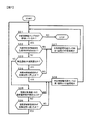
図6は、空調用回路2000に設けられた空調用容積可変タンク8Aの制御の一例を示すフローチャートである。ステップS11では、空調用循環ポンプ5Aが駆動しているか否かを判定する。ステップS11で空調用循環ポンプ5Aが駆動していると判定されるとステップS12へ進み、駆動していないと判定されると図6の制御処理を終了する。このステップS11の判定処理は、空調用循環ポンプ5Aの駆動の有無に基づいて、空調用容積可変タンク8Aの制御処理を続けるか否かを判断するものである。すなわち、空調用循環ポンプ5Aが駆動中で空調用熱移動媒体が空調用回路2000を循環している場合には、空調用容積可変タンク8Aの制御処理を継続すべくステップS12へ進む。一方、ステップS11で空調用循環ポンプ5Aが停止していると判定された場合には、空調用容積可変タンク8Aを動作させる必要がないので、空調用容積可変タンク8Aの制御処理を終了する。
(Control of air-conditioning volume variable tank 8A)
FIG. 6 is a flowchart showing an example of control of the air conditioning volume variable tank 8A provided in the air conditioning circuit 2000. In step S11, it is determined whether or not the air-conditioning circulation pump 5A is driven. If it is determined in step S11 that the air-conditioning circulation pump 5A is driven, the process proceeds to step S12. If it is determined that the air-conditioning circulation pump 5A is not driven, the control process of FIG. The determination process in step S11 is to determine whether or not to continue the control process of the air conditioning volume variable tank 8A based on whether or not the air conditioning circulation pump 5A is driven. That is, when the air conditioning circulation pump 5A is being driven and the air conditioning heat transfer medium is circulating in the air conditioning circuit 2000, the process proceeds to step S12 to continue the control processing of the air conditioning volume variable tank 8A. On the other hand, when it is determined in step S11 that the air-conditioning circulation pump 5A is stopped, the air-conditioning volume variable tank 8A does not need to be operated, and thus the control processing of the air-conditioning volume variable tank 8A is terminated.

ところで、空調用循環ポンプ5Aが駆動されて空調が動作中であっても、空調用熱移動媒体の温度が予め決められた目標温度に到達していないと、車室内に吹き出される空気の温度を適温にすることができない。そこで、ステップS12では、図1に示した温度センサ2001で検出された空調用熱移動媒体の温度と、空調用熱移動媒体の目標温度とを比較し、空調用熱移動媒体の温度が目標温度に達したか否かを判定する。この目標温度は、空調設定温度に応じて制御装置4000において決定される温度である。   By the way, even if the air-conditioning circulation pump 5A is driven and the air-conditioning is in operation, if the temperature of the air-conditioning heat transfer medium does not reach the predetermined target temperature, the temperature of the air blown into the passenger compartment Can not reach the proper temperature. Therefore, in step S12, the temperature of the air-conditioning heat transfer medium detected by the temperature sensor 2001 shown in FIG. 1 is compared with the target temperature of the air-conditioning heat transfer medium. It is determined whether or not it has been reached. This target temperature is a temperature determined by control device 4000 in accordance with the air conditioning set temperature.

ステップS12において目標温度に達していないと判定されると、ステップS15に進む。ステップS15では、空調用熱移動媒体の温度が早急に目標温度となるように、図2に示す断熱パーティション25を下方に移動して、空調用容積可変タンク8Aの第1空間23の容積を減少させる。前述したように、空調用容積可変タンク8Aの第1空間23の容積が減少すると、空調用回路2000内を循環する空調用熱移動媒体の量が減少して熱容量が小さくなるので、温度変化速度が速くなってより短時間で目標温度に達するようになる。ステップS15における容積変化量は、予め設定された所定量でも良いし、目標温度と検出された空調用熱移動媒体の温度との差に応じて設定するようにしても良い。   If it is determined in step S12 that the target temperature has not been reached, the process proceeds to step S15. In step S15, the heat insulating partition 25 shown in FIG. 2 is moved downward so that the temperature of the air conditioning heat transfer medium quickly reaches the target temperature, thereby reducing the volume of the first space 23 of the air conditioning volume variable tank 8A. Let As described above, when the volume of the first space 23 of the air conditioning volume variable tank 8A decreases, the amount of the air conditioning heat transfer medium circulating in the air conditioning circuit 2000 decreases and the heat capacity decreases. Becomes faster and reaches the target temperature in a shorter time. The volume change amount in step S15 may be a predetermined amount set in advance, or may be set according to the difference between the target temperature and the detected temperature of the air-conditioning heat transfer medium.

ステップS15において断熱パーティション25を下方に移動させたならば、ステップS11に戻り、ステップS11,S12の処理を再び順に行う。そして、空調用熱移動媒体の温度が目標温度に達するまで、ステップS11,S12,S15の処理が繰り返し実行される。なお、ステップS15において、圧縮機1の回転数を上昇させる処理をさらに行うようにしても良い。それにより冷凍サイクル回路1000の温調能力が高まり、より早期に目標温度に達することができる。また、空調始動時においては、空調用容積可変タンク8Aの第1空間23の容積は下限値に設定されているので、ステップS15の処理で断熱パーティション25は移動されず、容積下限値が維持されることになる。   If the heat insulation partition 25 is moved downward in step S15, it will return to step S11 and will perform the process of step S11, S12 again in order. And the process of step S11, S12, S15 is repeatedly performed until the temperature of the heat transfer medium for an air conditioning reaches target temperature. In step S15, a process of increasing the rotation speed of the compressor 1 may be further performed. Thereby, the temperature control capability of the refrigeration cycle circuit 1000 is increased, and the target temperature can be reached earlier. Further, at the time of air conditioning start, the volume of the first space 23 of the air conditioning volume variable tank 8A is set to the lower limit value. Therefore, the heat insulation partition 25 is not moved by the process of step S15, and the volume lower limit value is maintained. Will be.

一方、ステップS12において空調用熱移動媒体の温度が目標温度に達したと判定されると、ステップS13へ進む。ステップS13では、空調用容積可変タンク8Aの第1空間23の容積が予め設定されている目標容積に達したか否かを判定する。ここで、第1空間23の目標容積とは、空調用回路2000が定常的に能力を発揮できる余裕を持った空調用熱移動媒体量(総量)を確保できる最適容積を意味する。例えば、空調用熱交換器10Aにおける熱交換量が変動したり、空調負荷が変動した場合でも、空調用熱移動媒体の温度変化を小さく抑えることができる程度に余裕を持たせている。上述した容積下限値は、一時的に熱応答速度を高めるための容積であって、この目標容積よりも小さく設定されている。   On the other hand, if it is determined in step S12 that the temperature of the air-conditioning heat transfer medium has reached the target temperature, the process proceeds to step S13. In step S13, it is determined whether or not the volume of the first space 23 of the air conditioning volume variable tank 8A has reached a preset target volume. Here, the target volume of the first space 23 means an optimal volume that can secure an air conditioning heat transfer medium amount (total amount) with a margin that the air conditioning circuit 2000 can constantly exert its capability. For example, even if the amount of heat exchange in the air conditioner heat exchanger 10A changes or the air conditioning load fluctuates, a margin is provided to such an extent that the temperature change of the air conditioning heat transfer medium can be kept small. The volume lower limit value described above is a volume for temporarily increasing the thermal response speed, and is set smaller than this target volume.

ステップS13で第1空間23の容積が目標容積に達したと判定されるとステップS14へ進み、目標容積に達していないと判定されるとステップS16へ進む。例えば、目標温度に到達させるためにステップS15で第1空間23の容積を容積下限値付近まで減少させた場合には、空調用回路2000を循環する空調用熱移動媒体の総量をシステムとして必要な量とするために、ステップS13でNOと判定しステップS16へ進む。   If it is determined in step S13 that the volume of the first space 23 has reached the target volume, the process proceeds to step S14, and if it is determined that the volume has not reached the target volume, the process proceeds to step S16. For example, when the volume of the first space 23 is reduced to near the volume lower limit value in step S15 in order to reach the target temperature, the total amount of the heat transfer medium for air conditioning circulating in the air conditioning circuit 2000 is required as a system. In order to obtain the quantity, NO is determined in step S13, and the process proceeds to step S16.

ステップS16では、空調用容積可変タンク8Aの第1空間23の容積を増大させる。なお、ステップS16における容積の増大は、空調用回路2000に振り分けられる冷凍サイクル回路1000の温調能力に応じて行われる。   In step S16, the volume of the first space 23 of the air conditioning volume variable tank 8A is increased. The increase in volume in step S16 is performed according to the temperature control capability of the refrigeration cycle circuit 1000 distributed to the air conditioning circuit 2000.

空調用容積可変タンク8Aの第1空間23の容積を増大させると、断熱パーティション25の連通穴26を通って第2空間24の空調用熱移動媒体が第1空間23に流れ込む。第2空間24に溜まっていた空調用熱移動媒体の温度は、周囲への放熱または周囲からの熱侵入によって、循環している空調用熱移動媒体の温度と異なっている。暖房時であれば循環している空調用熱移動媒体の温度よりも低く、逆に冷房時であれば、循環している空調用熱移動媒体の温度よりも高い。そのため、冷凍サイクル回路1000から空調用回路2000に振り分けられる温調能力に余裕がないと、第1空間23の容積を増大させたときに空調用熱移動媒体の温度が変動してしまうことになる。   When the volume of the first space 23 of the air conditioning volume variable tank 8 </ b> A is increased, the heat transfer medium for air conditioning in the second space 24 flows into the first space 23 through the communication hole 26 of the heat insulating partition 25. The temperature of the air-conditioning heat transfer medium accumulated in the second space 24 is different from the temperature of the circulating air-conditioning heat transfer medium due to heat radiation to the surroundings or heat penetration from the surroundings. When heating, the temperature is lower than the temperature of the circulating air-conditioning heat transfer medium. Conversely, when cooling, the temperature is higher than the temperature of the circulating air-conditioning heat transfer medium. Therefore, if there is no allowance for the temperature control capability distributed from the refrigeration cycle circuit 1000 to the air conditioning circuit 2000, the temperature of the air conditioning heat transfer medium will fluctuate when the volume of the first space 23 is increased. .

そのため、第1空間23の容積を増大させる場合には、冷凍サイクル回路1000の温調能力の余裕分だけ増大させる。例えば、第2空間24に滞留している空調用熱移動媒体の温度を温度センサで検出し、空調用回路2000を循環している空調用熱移動媒体の温度と第2空間24に滞留している空調用熱移動媒体の温度との差と、冷凍サイクル回路1000の温調能力とに基づいて、ステップS16における容積増大量を推定し、その推定結果に基づいて断熱パーティション25を移動させる。   Therefore, when the volume of the first space 23 is increased, the first space 23 is increased by a margin of the temperature adjustment capability of the refrigeration cycle circuit 1000. For example, the temperature of the air-conditioning heat transfer medium staying in the second space 24 is detected by a temperature sensor, and the temperature of the air-conditioning heat transfer medium circulating in the air-conditioning circuit 2000 is staying in the second space 24. Based on the difference between the temperature of the air-conditioning heat transfer medium and the temperature adjustment capability of the refrigeration cycle circuit 1000, the volume increase in step S16 is estimated, and the heat insulating partition 25 is moved based on the estimation result.

このように構成することにより、空調用回路2000を循環する空調用熱移動媒体の熱容量大きくなり、空調用熱移動媒体の温度が変動しにくくなる。その結果、空調の快適性を向上させることができる。ステップS16の処理が終了したら、ステップS11へ戻る。 With this configuration, the heat capacity of the air-conditioning heat transfer medium circulating in the air-conditioning circuit 2000 is increased, and the temperature of the air-conditioning heat transfer medium is less likely to fluctuate. As a result, the comfort of air conditioning can be improved. When the process of step S16 ends, the process returns to step S11.

一方、ステップS13において空調用容積可変タンク8Aの第1空間23の容積が目標容積に達している場合には、ステップS14に進む。ステップS14では上位制御装置5000からの車両情報に基づいて、空調用回路2000と冷却用回路3000の必要能力が冷凍サイクル回路1000の最大温調能力を超える見込みがあるか否かを判定する。   On the other hand, if the volume of the first space 23 of the air conditioning volume variable tank 8A has reached the target volume in step S13, the process proceeds to step S14. In step S14, based on the vehicle information from the host controller 5000, it is determined whether or not the required capacity of the air conditioning circuit 2000 and the cooling circuit 3000 is likely to exceed the maximum temperature control capacity of the refrigeration cycle circuit 1000.

ここで車両情報とは、車両制御装置側から入力される車速情報やカーナビゲーション情報などである。例えば、車速が増加する傾向にある場合には、温調対象機器16の発熱量増大により空調および機器冷却に必要な能力の増大が見込まれる。また、ナビゲーション情報から山道が予測されるような場合にも、機器冷却に必要な能力の増大が推定される。   Here, the vehicle information is vehicle speed information, car navigation information, or the like input from the vehicle control device side. For example, when the vehicle speed tends to increase, an increase in heat generation capacity of the temperature control target device 16 is expected to increase the capacity required for air conditioning and device cooling. Further, even when a mountain road is predicted from the navigation information, an increase in capacity necessary for equipment cooling is estimated.

その結果、温調対象機器16の発熱量が一時的に増大し、温調対象機器16の冷却と車室内の空調の維持に必要な冷凍サイクル回路1000の温調能力が、冷凍サイクル回路1000の最大温調能力を超える見込みがある場合には、ステップS14からステップS16に進んで、空調用容積可変タンク8Aの第1空間23の容積を予め増大させる。   As a result, the heat generation amount of the temperature control target device 16 temporarily increases, and the temperature control capability of the refrigeration cycle circuit 1000 necessary for cooling the temperature control target device 16 and maintaining the air conditioning in the passenger compartment is If there is a possibility of exceeding the maximum temperature control capability, the process proceeds from step S14 to step S16, and the volume of the first space 23 of the air conditioning volume variable tank 8A is increased in advance.

このように構成することにより、空調用熱移動媒体の熱容量が大きくなり、空調用熱移動媒体の温度変化が遅くなるため、空調用熱移動媒体の温度変化が遅くなるため、空調用熱交換10Aへ流れる冷媒の流量を減少させたり、又は冷媒を停止させたりしても、一時的に空調の吹き出し温度を適温に維持することができる。これにより、一時的に冷凍サイクル回路1000の温調能力を温調対象機器16の冷却に集中的に振り分けることができる。 With this configuration, the heat capacity of the air-conditioning heat transfer medium is increased, and the temperature change of the air-conditioning heat transfer medium is delayed. Therefore, the temperature change of the air-conditioning heat transfer medium is delayed . Even if the flow rate of the refrigerant flowing to 10A is reduced or the refrigerant is stopped, the air-conditioning blowout temperature can be temporarily maintained at an appropriate temperature. Thereby, the temperature control capability of the refrigeration cycle circuit 1000 can be temporarily concentrated on cooling of the temperature control target device 16.

ステップS14でNOと判定された場合には、ステップS11へ戻る。このように、空調用回路2000に空調用容積可変タンク8Aを設けて、第1空間23の容積を変化させることで空調用熱移動媒体の熱容量を小さくしたり、逆に大きくしたりすることで、熱応答速度を高めて空調温度を素早く適温にしたり、一時的に空調側への温調能力の振り分けが小さくなった場合の空調温度の変動を抑えたりすることができる。その結果、空調の快適性を向上させることができる。   If NO is determined in step S14, the process returns to step S11. In this way, by providing the air conditioning volume variable tank 8A in the air conditioning circuit 2000 and changing the volume of the first space 23, the heat capacity of the heat transfer medium for air conditioning can be reduced or conversely increased. It is possible to increase the thermal response speed to quickly adjust the air conditioning temperature to an appropriate temperature, or to suppress fluctuations in the air conditioning temperature when the distribution of the temperature control capability to the air conditioning side temporarily decreases. As a result, the comfort of air conditioning can be improved.

(冷却用容積可変タンク8Bの制御処理)
次に、図7のフローチャートを用いて、冷却用容積可変タンク8Bの制御処理について説明する。図7のステップS21の処理は、上述した図6のフローチャートのステップS11の処理と同様の処理である。すなわち、ステップS21では、冷却用循環ポンプ5Bが駆動しているか否かを判定し、駆動していないと判定されると冷却用容積可変タンク8Bの制御処理を終了し、駆動中の場合にはステップS22へ進む。
(Control processing of cooling capacity variable tank 8B)
Next, the control processing of the cooling volume variable tank 8B will be described using the flowchart of FIG. The process in step S21 in FIG. 7 is the same as the process in step S11 in the flowchart in FIG. 6 described above. That is, in step S21, it is determined whether or not the cooling circulation pump 5B is driven. If it is determined that the cooling circulation pump 5B is not driven, the control processing for the cooling volume variable tank 8B is terminated. Proceed to step S22.

ステップS22では、温調対象機器16の発熱量が一時的に増大し、冷却用熱移動媒体を急速に冷却する必要があるか否かを判定する。温調対象機器16の発熱量増大としては、モータ負荷の増大によるモータやインバータの発熱量増加があり温調対象機器16の温度は温度センサ3001によって検出される。ステップS22では、温度センサ3001の検出温度に基づいて、冷却用熱移動媒体を急速に冷却する必要があるか否かを判定する。   In step S22, it is determined whether or not the heat generation amount of the temperature control target device 16 temporarily increases and it is necessary to rapidly cool the cooling heat transfer medium. As an increase in the heat generation amount of the temperature adjustment target device 16, there is an increase in the heat generation amount of the motor or the inverter due to an increase in the motor load. In step S22, it is determined whether or not the cooling heat transfer medium needs to be rapidly cooled based on the temperature detected by the temperature sensor 3001.

なお、ここでは、温度センサ3001の検出温度に基づいて、冷却用熱移動媒体を急速に冷却する必要があるか否かを判定したが、図6のステップS14の場合と同じように、上位制御装置5000からの車両情報とに基づいて、冷却用熱移動媒体の急速冷却の必要性を予測するようにしても良い。急速冷却が必要と予測されたならば、ステップS27の処理を行って、予め冷却用熱移動媒体の温度を下げておき、温調対象機器16の温度上昇に備えるようにする。   Here, it is determined whether or not the cooling heat transfer medium needs to be rapidly cooled based on the temperature detected by the temperature sensor 3001. However, as in the case of step S14 in FIG. Based on the vehicle information from the device 5000, the necessity for rapid cooling of the cooling heat transfer medium may be predicted. If it is predicted that rapid cooling is necessary, the process of step S27 is performed, and the temperature of the heat transfer medium for cooling is lowered in advance to prepare for the temperature rise of the temperature adjustment target device 16.

ステップS22で冷却用熱移動媒体を急速に冷却する必要があると判定されると、ステップS27へ進んで冷却用容積可変タンク8Bの第1空間23の容積を減少させる。その結果、冷却用回路300を循環する冷却用熱移動媒体の熱容量が小さくなり、冷却用熱移動媒体を早期に目標温度まで低下させることができる。このように、温調対象機器16の一時的な発熱増大に対しては、ステップS22およびステップS27の処理により、すなわち冷却用容積可変タンク8Bの第1空間23の容積減少により効果的に対処することができる。一方、ステップS22において冷却用熱移動媒体を急速に冷却する必要がないと判定された場合には、ステップS23へ進む。   If it is determined in step S22 that the cooling heat transfer medium needs to be rapidly cooled, the process proceeds to step S27, and the volume of the first space 23 of the cooling volume variable tank 8B is decreased. As a result, the heat capacity of the cooling heat transfer medium circulating in the cooling circuit 300 is reduced, and the cooling heat transfer medium can be quickly lowered to the target temperature. As described above, the temporary increase in heat generation of the temperature adjustment target device 16 is effectively dealt with by the processing of step S22 and step S27, that is, by reducing the volume of the first space 23 of the cooling volume variable tank 8B. be able to. On the other hand, if it is determined in step S22 that it is not necessary to rapidly cool the cooling heat transfer medium, the process proceeds to step S23.

ところで、上述した空調用回路2000の空調用容積可変タンク8Aの場合と異なり、冷却用容積可変タンク8Bの制御の仕方は、冷却空調システムの運転動作によって異なる。すなわち、除湿運転および暖房運転の場合には温調対象機器16の排熱を、暖房に利用しているので、冷却用熱移動媒体に対して暖房として利用できるための目標温度がある。例えば、暖房運転のときは、空調側室内熱交換器15Aで暖められた空気が、冷却側室内熱交換器15Bでさらに暖められる構成となっているので、冷却用熱移動媒体の温度は、空調用熱移動媒体の温度、より正確には冷却側室内熱交換器15Bに流入する空気の温度よりも高くなっていることが必要である。ただし、温調対象機器16に不具合が生じない程度の温度が目標温度として選ばれる。その要求温度が目標温度であって、例えば、40℃程度が選ばれる。   By the way, unlike the case of the air conditioning volume variable tank 8A of the air conditioning circuit 2000 described above, the way of controlling the cooling volume variable tank 8B differs depending on the operation of the cooling air conditioning system. In other words, in the case of the dehumidifying operation and the heating operation, the exhaust heat of the temperature adjustment target device 16 is used for heating, so there is a target temperature that can be used as heating for the cooling heat transfer medium. For example, during the heating operation, the air heated by the air conditioning side indoor heat exchanger 15A is further heated by the cooling side indoor heat exchanger 15B. It is necessary that the temperature of the heat transfer medium for use is higher than the temperature of the air flowing into the cooling-side indoor heat exchanger 15B, more precisely. However, a temperature that does not cause a problem in the temperature adjustment target device 16 is selected as the target temperature. The required temperature is a target temperature, for example, about 40 ° C. is selected.

一方、冷房運転および冷却暖房運転の場合には排熱をこのように利用していない。そのため、ステップS23の判断処理では、冷却空調システムの運転動作が除湿運転か暖房運転の場合にはステップS24へ進み、運転動作が冷房運転か冷却暖房運転であればステップS25へ進む。   On the other hand, in the case of cooling operation and cooling / heating operation, exhaust heat is not used in this way. Therefore, in the determination process of step S23, when the operation of the cooling air conditioning system is the dehumidifying operation or the heating operation, the process proceeds to step S24, and when the operation is the cooling operation or the cooling / heating operation, the process proceeds to step S25.

除湿運転の時や暖房運転の始動時などにおいて、冷却用熱移動媒体の温度が空調用熱移動媒体の温度よりも低い場合には、除湿運転や暖房運転を効果的に行わせるために、冷却用熱移動媒体の温度を早期に上述の目標温度まで上昇させることが望ましい。そのため、ステップS24に進んだ場合には、ステップS24で冷却用熱移動媒体の検出温度と上記目標温度とを比較する。そして、ステップS24において冷却用熱移動媒体が目標温度より低いと判定された場合には、場合にはステップS27へ移動して、冷却用容積可変タンク8Bの第1空間23の容積を減少させる。このように構成することにより、冷却用回路3000を循環する冷却用熱移動媒体の熱容量が小さくなり、冷却用熱移動媒体を早期に目標温度まで上昇させることができる。   When the temperature of the heat transfer medium for cooling is lower than the temperature of the heat transfer medium for air conditioning during dehumidifying operation or starting of heating operation, cooling is performed to effectively perform the dehumidifying operation or heating operation. It is desirable to raise the temperature of the heat transfer medium for use to the above-mentioned target temperature at an early stage. Therefore, when the process proceeds to step S24, the detected temperature of the cooling heat transfer medium is compared with the target temperature in step S24. If it is determined in step S24 that the cooling heat transfer medium is lower than the target temperature, the process moves to step S27 to decrease the volume of the first space 23 of the cooling volume variable tank 8B. With this configuration, the heat capacity of the cooling heat transfer medium circulating through the cooling circuit 3000 is reduced, and the cooling heat transfer medium can be quickly raised to the target temperature.

ステップS24において冷却用熱移動媒体の温度が目標温度に達したと判定された場合には、ステップS28へ進み、冷却用容積可変タンク8Bの第1空間23の容積を、温調対象機器16の発熱量に応じて増大させる。ステップS28の処理は、図6のステップS16と同様の処理であり、ステップS28の処理によって冷却用回路3000を循環する冷却用熱移動媒体の熱容量が大きくなり、冷却用熱移動媒体の温度が変化し難くなる。その結果、空調の吹き出し温度の変動が小さくなり、空調の快適性を向上させることができる。   If it is determined in step S24 that the temperature of the cooling heat transfer medium has reached the target temperature, the process proceeds to step S28, and the volume of the first space 23 of the cooling volume variable tank 8B is set to the temperature adjustment target device 16. Increase according to the amount of heat generation. The process of step S28 is the same process as step S16 of FIG. 6, and the heat capacity of the cooling heat transfer medium circulating through the cooling circuit 3000 is increased by the process of step S28, and the temperature of the cooling heat transfer medium changes. It becomes difficult to do. As a result, the fluctuation of the air-conditioning blowout temperature is reduced, and the comfort of the air-conditioning can be improved.

一方、運転動作が冷房運転か冷却暖房運転であって、ステップS23からステップS25へ進んだ場合には、温調対象機器16の発熱量変動が規定値以上か否かを判定する。この判定は、車両側から送信されるモータの運転情報、具体的にはモータ要求トルクに基づいて判定を行う。   On the other hand, when the operation is the cooling operation or the cooling / heating operation and the process proceeds from step S23 to step S25, it is determined whether or not the heat generation amount variation of the temperature adjustment target device 16 is equal to or greater than a specified value. This determination is performed based on motor operation information transmitted from the vehicle side, specifically, motor request torque.

山道走行などにおいてモータ運転状況が頻繁に変化し、温調対象機器16の発熱量の変動が激しい場合がある。そのような場合には冷却用熱移動媒体の温度変化が大きく、それに対応して冷却側流量制御弁2Bの開閉量や圧縮機1の回転数が頻繁に変化する。このような状態は、圧縮機1の消費エネルギ増大や、圧縮機1、冷却側流量制御弁2Bの寿命低下を招き、好ましくない。   There is a case where the motor operation status frequently changes during traveling on a mountain road, and the amount of heat generated by the temperature control target device 16 varies greatly. In such a case, the temperature change of the cooling heat transfer medium is large, and the opening / closing amount of the cooling-side flow rate control valve 2B and the rotation speed of the compressor 1 frequently change accordingly. Such a state is not preferable because it leads to an increase in energy consumption of the compressor 1 and a decrease in the service life of the compressor 1 and the cooling side flow control valve 2B.

そのため、ステップS25では、モータ要求トルク情報に基づいて、温調対象機器16の発熱量変動が規定値以上になることが判定された場合には、ステップS28へ進んで、冷却用容積可変タンク8Bの第1空間23の容積を増大させる。ここで、規定値とは、圧縮機1の消費エネルギ増大や、圧縮機1、冷却側流量制御弁2Bの寿命低下を招く程度の発熱量変動であり、予め設定されている。その結果、冷却用回路3000を循環する冷却用熱移動媒体の熱容量が大きくなり、温調対象機器16の発熱量の変動が激しい場合であっても、冷却用熱移動媒体の温度変化を抑えることができる。   Therefore, in step S25, when it is determined that the heat generation amount fluctuation of the temperature adjustment target device 16 is equal to or greater than the specified value based on the motor request torque information, the process proceeds to step S28 and the cooling volume variable tank 8B. The volume of the first space 23 is increased. Here, the specified value is a calorific value fluctuation that causes an increase in energy consumption of the compressor 1 and a decrease in the service life of the compressor 1 and the cooling-side flow rate control valve 2B, and is set in advance. As a result, the heat capacity of the cooling heat transfer medium that circulates through the cooling circuit 3000 is increased, and even if the heat generation amount of the temperature control target device 16 varies greatly, the temperature change of the cooling heat transfer medium is suppressed. Can do.

なお、ステップS25において、モータ情報としてモータ要求トルクに代えてモータ温度や冷却用熱移動媒体の温度情報を用いることもできる。ただし、モータ温度を用いる場合にはモータ温度が実際に上昇したことを検出してから対応するので、モータ要求トルク情報を用いるほうがより早期に対応することが可能となる。もちろん、モータ温度情報とモータ要求トルク情報との両方を用いて、より正確にモータ温度上昇を予測するようにしても良い。   In step S25, the motor information and the temperature information of the cooling heat transfer medium can be used as the motor information instead of the motor required torque. However, since the motor temperature is used after the fact that the motor temperature has actually been detected, it is possible to respond earlier by using the motor required torque information. Of course, the motor temperature increase may be predicted more accurately using both the motor temperature information and the motor required torque information.

ステップS25の処理が終了したら、ステップS21へ戻る。一方、ステップS25において、温調対象機器16の発熱量変動が規定値以下であると判定された場合には、ステップS26へ進む。   When the process of step S25 is completed, the process returns to step S21. On the other hand, if it is determined in step S25 that the heat generation amount fluctuation of the temperature adjustment target device 16 is not more than the specified value, the process proceeds to step S26.

冷房運転や冷却暖房運転の始動時に、空調用熱移動媒体が目標温度に達していない状況においては、冷凍サイクル回路1000の温調能力を空調側に積極的に振り分けて早期に目標温度とするのが好ましい。そのように温調能力の振り分けを行うためには、冷却用熱移動媒体の温度が温調対象機器16の許容温度から決まる規定値以下となっている必要がある。さらに、冷却側に振り分けられる温調能力が減少しても、冷却用熱移動媒体の温度が上昇し過ぎないように、冷却用熱移動媒体の熱容量を大きくしておく必要がある。 When the air-conditioning heat transfer medium does not reach the target temperature at the start of the cooling operation or the cooling / heating operation, the temperature adjustment capability of the refrigeration cycle circuit 1000 is actively distributed to the air-conditioning side to quickly reach the target temperature. Is preferred. In order to distribute the temperature control capability in this way, the temperature of the cooling heat transfer medium needs to be equal to or less than a specified value determined from the allowable temperature of the temperature control target device 16. Furthermore, it is necessary to increase the heat capacity of the cooling heat transfer medium so that the temperature of the cooling heat transfer medium does not rise too much even if the temperature control ability distributed to the cooling side decreases.

そこで、ステップS26では、空調用熱移動媒体の温度が目標温度に到達したか否かを判定し、目標温度に達していない場合には、ステップS28に進んで冷却用容積可変タンク8Bの第1空間23の容積を増大させる。このような制御を行うことにより、冷却用回路3000を循環する冷却用熱移動媒体の熱容量が大きくなり、空調側への温調能力の振り分けを増加させるために冷却用熱交換10Bへの冷媒の流量を減少させたり、冷媒の流れを停止させた場合であっても、冷却用熱移動媒体の温度上昇を抑制または遅らせることができる。これにより、一時的に冷凍サイクル回路1000の温調能力を空調に集中的に振り分けることができ、空調用熱移動媒体を早期に目標温度にすることができる。 Therefore, in step S26, it is determined whether or not the temperature of the air-conditioning heat transfer medium has reached the target temperature. If the target temperature has not been reached, the process proceeds to step S28, and the first variable volume tank 8B for cooling is set. The volume of the space 23 is increased. By performing such control, the heat capacity of the cooling heat-transfer medium circulating in the cooling circuit 3000 is increased, the refrigerant in the cooling heat exchanger 10B in order to increase the distribution of temperature control capability of the air-conditioning side Even when the flow rate of the refrigerant is reduced or the flow of the refrigerant is stopped, the temperature increase of the cooling heat transfer medium can be suppressed or delayed. Thereby, the temperature control capability of the refrigeration cycle circuit 1000 can be temporarily allocated to air conditioning in a concentrated manner, and the heat transfer medium for air conditioning can be brought to the target temperature at an early stage.

ステップS26の処理が終了したら、ステップS21へ戻る。このように、本実施の形態では、容積可変タンク8A,8Bを設けたことにより、熱移動媒体の容積を減少することで温度応答速度を速くしたり、熱移動媒体の容積を増大することで温度応答速度を遅くして、温度安定性の向上を図ったりすることができる。すなわち、熱移動媒体の温度応答速度を状況に応じて変えることが可能となる。   When the process of step S26 ends, the process returns to step S21. As described above, in the present embodiment, by providing the variable volume tanks 8A and 8B, the temperature response speed can be increased by decreasing the volume of the heat transfer medium, or the volume of the heat transfer medium can be increased. It is possible to improve the temperature stability by slowing the temperature response speed. That is, the temperature response speed of the heat transfer medium can be changed according to the situation.

−第2の実施の形態−
以下に説明する第2の実施の形態では、上述した第1の実施の形態における冷却用容積可変タンク8Bの構成を変更した。なお、図1から図5に示す要素と同様な要素に対しては同一の符号を付して相違点を中心に説明する。
-Second Embodiment-
In the second embodiment described below, the configuration of the cooling volume variable tank 8B in the first embodiment described above is changed. The same elements as those shown in FIGS. 1 to 5 are denoted by the same reference numerals, and different points will be mainly described.

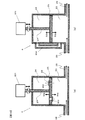
図8は、第2の実施の形態における冷却用容積可変タンク8Bの概略構成を示す図である。冷却用容積可変タンク8Bは、断熱パーティション25で仕切られた第1空間23および第2空間24を備えている。断熱パーティション25は連通26が形成されており、駆動軸27によって図示上下に移動することができる。第2の実施の形態の冷却用容積可変タンク8Bにおいては、冷却用熱移動媒体を流入させるための2つの流入口(第1流入口30および第2流入口31)と、冷却用熱移動媒体を流出させるための2つの流出口(第1流出口32および第2流出口33)とを備えている。 FIG. 8 is a diagram showing a schematic configuration of the cooling volume variable tank 8B in the second embodiment. The cooling volume variable tank 8 </ b> B includes a first space 23 and a second space 24 partitioned by a heat insulating partition 25. Adiabatic partition 25 is communicating hole 26 is formed, it is possible to move the drawing up and down by the drive shaft 27. In the cooling variable volume tank 8B of the second embodiment, two inlets (first inlet 30 and second inlet 31) for allowing the cooling heat transfer medium to flow in, and the cooling heat transfer medium 2 outflow ports (first outflow port 32 and second outflow port 33).

第1流入口30は、第1入口三方弁34を介して第1空間23および第2空間24の入口側に接続されている。すなわち、第1入口三方弁34を切り換えることによって、第1流入口30は、第1空間23および第2空間24のいずれか一方に選択的に接続される。第2流入口31は、第2入口三方弁35を介して第1空間23および第2空間24の入口側に接続されている。すなわち、第2入口三方弁35を切り換えることによって、第2流入口31は、第1空間23および第2空間24のいずれか一方に選択的に接続される。   The first inlet 30 is connected to the inlet side of the first space 23 and the second space 24 via the first inlet three-way valve 34. That is, by switching the first inlet three-way valve 34, the first inlet 30 is selectively connected to one of the first space 23 and the second space 24. The second inlet 31 is connected to the inlet side of the first space 23 and the second space 24 via the second inlet three-way valve 35. That is, by switching the second inlet three-way valve 35, the second inlet 31 is selectively connected to one of the first space 23 and the second space 24.

一方、第1空間23の出口側には第1出口三方弁36が設けられている。第1空間23は、第1出口三方弁36を切り換えることによって、第1流出口32および第2流出口33のいずれか一方に選択的に接続される。なお、第1出口三方弁36と第2流出口33との間には第1出口交差流路40が設けられている。また、第2空間24の出口側には第2出口三方弁37が設けられている。第2空間24は、第2出口三方弁37を切り換えることによって、第1流出口32および第2流出口33のいずれか一方に選択的に接続される。なお、第2出口三方弁37と第1流出口32との間には第2出口交差流路41が設けられている。   On the other hand, a first outlet three-way valve 36 is provided on the outlet side of the first space 23. The first space 23 is selectively connected to either the first outlet 32 or the second outlet 33 by switching the first outlet three-way valve 36. A first outlet cross passage 40 is provided between the first outlet three-way valve 36 and the second outlet 33. A second outlet three-way valve 37 is provided on the outlet side of the second space 24. The second space 24 is selectively connected to one of the first outlet 32 and the second outlet 33 by switching the second outlet three-way valve 37. A second outlet cross passage 41 is provided between the second outlet three-way valve 37 and the first outlet 32.

本実施の形態の冷却用容積可変タンク8Bにおいても、断熱パーティション25を矢印50a、矢印50bの方向に駆動することで第1空間23と第2空間24の容積比を変化させることができる。すなわち、断熱パーティション25を矢印50aの方向に駆動すると、第1空間23の容積が減少し、第2空間24の容積が増大する。逆に、断熱パーティション25を矢印50bの方向駆動すると、第1空間23の容積が増大し、第2空間24の容積が減少する。 Also in the cooling variable volume tank 8B of the present embodiment, the volume ratio between the first space 23 and the second space 24 can be changed by driving the heat insulating partition 25 in the directions of the arrows 50a and 50b. That is, when the heat insulating partition 25 is driven in the direction of the arrow 50a, the volume of the first space 23 decreases and the volume of the second space 24 increases. Conversely, when driving the heat insulating partition 25 in the direction of arrow 50b, the volume of the first space 23 increases, the volume of the second space 24 is decreased.

第1流入口30および第1流出口32は冷却用回路3000に接続されている。すなわち、図1に示す主回路19、バイパス回路20を通った冷却用熱移動媒体は冷却用容積可変タンク8Bの第1流入口30へ流入し、冷却用容積可変タンク8Bの第1流出口32から流出した冷却用熱移動媒体は温調対象機器16へ流入される。   The first inlet 30 and the first outlet 32 are connected to the cooling circuit 3000. That is, the cooling heat transfer medium that has passed through the main circuit 19 and the bypass circuit 20 shown in FIG. 1 flows into the first inlet 30 of the variable cooling tank 8B, and the first outlet 32 of the variable cooling tank 8B. The cooling heat transfer medium flowing out from the air flows into the temperature control target device 16.

一方、第2流入口31および第2流出口33は、冷却用回路3000とは別に設けられた放熱回路6000に接続されている。放熱回路6000には、放熱熱交換器43、循環ポンプ44、放熱熱交換器43に備えられた放熱ファン45が設けられている。循環ポンプ44を駆動すると、冷却用容積可変タンク8Bの第2流出口33から流出した冷却用熱移動媒体は、循環ポンプ44および放熱熱交換器43を経由して冷却用容積可変タンク8Bの第2流入口31に流入する。放熱ファン45を駆動することにより放熱熱交換器43の中の冷却用熱移動媒体は外気と熱交換し、放熱熱交換器43の中の冷却用熱移動媒体の温度が外気温度以下の場合には冷却される。 On the other hand, the second inlet 31 and the second outlet 33 are connected to a heat radiation circuit 6000 provided separately from the cooling circuit 3000. The heat dissipating circuit 6000 is provided with a heat dissipating heat exchanger 43, a circulation pump 44, and a heat dissipating fan 45 provided in the heat dissipating heat exchanger 43. When the circulation pump 44 is driven, the cooling heat transfer medium flowing out from the second outlet 33 of the cooling volume variable tank 8B passes through the circulation pump 44 and the radiating heat exchanger 43 to the second volume of the cooling volume variable tank 8B. 2 flows into the inlet 31. The cooling heat transfer medium in the heat dissipation heat exchanger 43 exchanges heat with the outside air by driving the heat dissipation fan 45, and the temperature of the cooling heat transfer medium in the heat dissipation heat exchanger 43 is equal to or lower than the outside air temperature. Is cooled.

本実施形態の冷却用容積可変タンク8Bでは、冷却用容積可変タンク8B内における冷却用熱移動媒体の流れ(流路形態)に関して2つの形態、すなわち標準モードと逆転モードとがある。標準モードは図8に示す形態であって、逆転モードは図9に示す形態である。   In the cooling variable volume tank 8B of the present embodiment, there are two modes, ie, a standard mode and a reverse mode, with respect to the flow (flow path configuration) of the cooling heat transfer medium in the cooling volume variable tank 8B. The standard mode is the form shown in FIG. 8, and the reverse mode is the form shown in FIG.

(標準モード)
まず、図8を用いて標準モードについて説明する。標準モードでは、第1入口三方弁34は第1流入口30と第1空間23とを接続し、第1出口三方弁36は第1空間23と第1流出口32とを接続し、第2入口三方弁35は第2流入口31と第2空間24とを接続し、第2出口三方弁37は第2空間24と第2流出口33とを接続する。そのため、第1流入口30から流入した冷却用熱移動媒体は、第1入口三方弁34、第1空間23および第1出口三方弁36を順に経由して第1流出口32から流出される。また、第2流入口31から流入した冷却用熱移動媒体は、第2入口三方弁35、第2空間24および第2出口三方弁37を順に経由して第2流出口33から流出される。
(Standard mode)
First, the standard mode will be described with reference to FIG. In the standard mode, the first inlet three-way valve 34 connects the first inlet 30 and the first space 23, the first outlet three-way valve 36 connects the first space 23 and the first outlet 32, and the second The inlet three-way valve 35 connects the second inlet 31 and the second space 24, and the second outlet three-way valve 37 connects the second space 24 and the second outlet 33. Therefore, the cooling heat transfer medium flowing in from the first inlet 30 flows out of the first outlet 32 through the first inlet three-way valve 34, the first space 23 and the first outlet three-way valve 36 in order. The cooling heat transfer medium flowing in from the second inlet 31 flows out of the second outlet 33 through the second inlet three-way valve 35, the second space 24 and the second outlet three-way valve 37 in order.

(逆転モード)
一方、図9に示す逆転モードでは、第1入口三方弁34は第1流入口30と第2空間24とを接続し、第2出口三方弁37は第2空間24と第1流出口32とを接続し、第2入口三方弁35は第2流入口31と第1空間23とを接続し、第1出口三方弁36は第1空間23と第2流出口33とを接続する。そのため、第1流入口30から流入した冷却用熱移動媒体は、第1入口三方弁34、第1入口交差流路38、第2空間24、第2出口三方弁37および第2出口交差流路41を順に経由して第1流出口32から流出される。また、第2流入口31から流入した冷却用熱移動媒体は、第2入口三方弁35、第2入口交差流路39、第1空間23、第1出口三方弁36および第1出口交差流路40を順に経由して第2流出口33から流出される。
(Reverse mode)
On the other hand, in the reverse rotation mode shown in FIG. 9, the first inlet three-way valve 34 connects the first inlet 30 and the second space 24, and the second outlet three-way valve 37 is connected to the second space 24 and the first outlet 32. The second inlet three-way valve 35 connects the second inlet 31 and the first space 23, and the first outlet three-way valve 36 connects the first space 23 and the second outlet 33. Therefore, the cooling heat transfer medium flowing in from the first inlet 30 flows through the first inlet three-way valve 34, the first inlet cross passage 38, the second space 24, the second outlet three-way valve 37, and the second outlet cross passage. It flows out from the 1st outflow port 32 through 41 in order. In addition, the cooling heat transfer medium flowing in from the second inlet 31 includes the second inlet three-way valve 35, the second inlet cross passage 39, the first space 23, the first outlet three-way valve 36, and the first outlet cross passage. It flows out from the 2nd outflow port 33 through 40 in order.

本実施の形態では、第1の実施の形態の冷却用容積可変タンク8Bの場合と同様に、断熱パーティション25を移動することによって第1空間23と第2空間24との容積比を変化させて、冷却用回路3000を循環する冷却用熱移動媒体の容積を変更するだけでなく、以下に説明するように、図8に示す標準モードと図9に示す逆転モードとを切り換えて用いることができる。   In the present embodiment, the volume ratio between the first space 23 and the second space 24 is changed by moving the heat insulating partition 25 as in the case of the variable volume tank for cooling 8B of the first embodiment. In addition to changing the volume of the cooling heat transfer medium circulating in the cooling circuit 3000, the standard mode shown in FIG. 8 and the reverse mode shown in FIG. 9 can be switched and used as described below. .

例えば、標準モードから逆転モードに切り換えた場合、標準モードでは冷却用容積可変タンク8Bの第1空間23が冷却用回路3000に接続されることになるが、逆転モードに切り換えると、第1空間23は冷却用回路3000と切り離され、第2空間24が冷却用回路3000に接続されることになる。   For example, when switching from the standard mode to the reverse rotation mode, the first space 23 of the cooling volume variable tank 8B is connected to the cooling circuit 3000 in the standard mode. Is disconnected from the cooling circuit 3000, and the second space 24 is connected to the cooling circuit 3000.

すなわち、冷却用回路3000に含まれる冷却用熱移動媒体を考えると、第1空間23の冷却用熱移動媒体が、放熱回路6000を構成する第2空間24の冷却用熱移動媒体に瞬時に交換されることになる。逆転モードから標準モードに切り換える場合も同様で、第2空間24の冷却用熱移動媒体が、放熱回路6000を構成する第1空間23の冷却用熱移動媒体に瞬時に交換されることになる。   That is, considering the cooling heat transfer medium included in the cooling circuit 3000, the cooling heat transfer medium in the first space 23 is instantly replaced with the cooling heat transfer medium in the second space 24 constituting the heat dissipation circuit 6000. Will be. The same applies to switching from the reverse rotation mode to the standard mode. The cooling heat transfer medium in the second space 24 is instantly replaced with the cooling heat transfer medium in the first space 23 constituting the heat dissipation circuit 6000.

上述したように、放熱回路6000に設けられている循環ポンプ44および放熱ファン45を駆動することにより、標準モードの場合には、冷却用容積可変タンク8Bの第1空間23内の冷却用熱移動媒体を外気温度に保つことができ、逆転モードの場合には、第2空間24内の冷却用熱移動媒体を外気温度に保つことができる。そのため、第1空間23の冷却用熱移動媒体の温度と第2空間24の冷却用熱移動媒体の温度とが異なるときに、例えば標準モードから逆転モードへ切り換えると、第1流出口32から流出されて温調対象機器16へ流入する冷却用熱移動媒体の温度を、第1空間23内の冷却用熱移動媒体の温度から、第2空間24内の冷却用熱移動媒体の温度へ、瞬時に切り換えることができる。   As described above, by driving the circulation pump 44 and the heat radiating fan 45 provided in the heat radiating circuit 6000, in the case of the standard mode, the heat transfer for cooling in the first space 23 of the cooling volume variable tank 8B. The medium can be kept at the outside air temperature, and in the case of the reverse rotation mode, the cooling heat transfer medium in the second space 24 can be kept at the outside air temperature. Therefore, when the temperature of the cooling heat transfer medium in the first space 23 and the temperature of the cooling heat transfer medium in the second space 24 are different, for example, when switching from the standard mode to the reverse mode, the first outflow port 32 flows out. The temperature of the cooling heat transfer medium flowing into the temperature control target device 16 is instantaneously changed from the temperature of the cooling heat transfer medium in the first space 23 to the temperature of the cooling heat transfer medium in the second space 24. Can be switched to.

例えば、冷房運転時や冷却暖房運転時に、温調対象機器16の発熱量増大が見込まれる場合がある。予め循環ポンプ44および放熱ファン45を駆動し、放熱回路6000を構成している第2空間24の冷却用熱移動媒体の温度を外気温度まで冷却しておく。なお、以下では、標準モードから逆転モードに切り換える場合を例に説明するが、逆転モードから標準モードに切り換える場合も同様である。   For example, an increase in the amount of heat generated by the temperature control target device 16 may be expected during cooling operation or cooling / heating operation. The circulation pump 44 and the heat radiating fan 45 are driven in advance, and the temperature of the cooling heat transfer medium in the second space 24 constituting the heat radiating circuit 6000 is cooled to the outside temperature. In the following, the case of switching from the standard mode to the reverse mode will be described as an example, but the same applies to the case of switching from the reverse mode to the standard mode.

そして、温調対象機器16の発熱量が一時的に増大し、冷却用熱移動媒体の温度を急速に下げる必要がある状況になったならば、まず、第1空間23と第空間24の容積比を変化させて、冷却用回路3000を循環する冷却用熱移動媒体の熱容量を小さくする。それでも間に合わない場合には、標準モードから逆転モードへ切り換え、温調対象機器16に流入する冷却用熱移動媒体の温度を瞬時に外気温まで下げる。もちろん、はじめから標準モードから逆転モードへ切り換えるようにしても良い。 If the amount of heat generated by the temperature control target device 16 temporarily increases and the temperature of the cooling heat transfer medium needs to be rapidly lowered, first, the first space 23 and the second space 24 The heat capacity of the cooling heat transfer medium circulating in the cooling circuit 3000 is reduced by changing the volume ratio. If still not in time, the standard mode is switched to the reverse mode, and the temperature of the cooling heat transfer medium flowing into the temperature adjustment target device 16 is instantaneously lowered to the outside temperature. Of course, the standard mode may be switched to the reverse mode from the beginning.

なお、上述した流路形態の切り換えは、1度でも良いし、温調対象機器16の発熱量増大状態が治まるまで数度繰り返し行っても良い。   Note that the switching of the flow path configuration described above may be performed once, or may be repeated several times until the heat generation amount increase state of the temperature adjustment target device 16 subsides.

一方、除湿運転や暖房運転の場合には、温調対象機器16の排熱を利用しているので、温調対象機器16の発熱量の一時的な増大に対しては、標準モードから逆転モードへと切り換えて冷却用熱移動媒体を急速に冷却し、温調対象機器16の過大な温度上昇を防止した後は、冷却用熱移動媒体の温度を排熱利用が可能な温度としておく必要がある。そのため、最初は冷房運転時や冷却暖房運転時と同様に、冷却用容積可変タンク8B内における流路形態の切り換えを行って、冷却回路3000の冷却用熱移動媒体の温度を急速に低下させる。ただし、切り換え後は、循環ポンプ44および放熱ファン45を停止して、放熱回路6000側に接続された第1空間23または第2空間24内の冷却用熱移動媒体の温度を、外気温まで低下させないようにする。 On the other hand, in the case of the dehumidifying operation or the heating operation, the exhaust heat of the temperature adjustment target device 16 is used. After the cooling heat transfer medium is rapidly cooled to prevent an excessive increase in temperature of the temperature control target device 16, the temperature of the cooling heat transfer medium needs to be set to a temperature at which exhaust heat can be used. is there. Therefore, as initially the time of the cooling operation or cooling heating operation, by performing the switching of the flow passage configuration of the cooling variable volume tank 8B, rapidly lowering the temperature of the cooling heat-transfer medium of the cooling circuit 3000 . However, after switching, the circulation pump 44 and the heat radiating fan 45 are stopped, and the temperature of the cooling heat transfer medium in the first space 23 or the second space 24 connected to the heat radiating circuit 6000 side is lowered to the outside air temperature. Do not let it.

そして、温調対象機器16の発熱量の一時的な増大が収まったならば、流路形態の切り換えを再び行って、すなわち逆転モードから標準モードに切り換えて、放熱回路6000側に接続されていた第1空間23内の冷却用熱移動媒体を冷却回路3000に戻す。上述したように、第1空間23が放熱回路6000に接続されているときには循環ポンプ44および放熱ファン45は停止されているので、戻された第1空間23内の冷却用熱移動媒体の温度は、標準モードから逆転モードに切り換えたときと比べて大きく変化していない。そのため、第1空間23内の冷却用熱移動媒体を冷却回路3000に戻したときに、冷却回路3000内の冷却用熱移動媒体の温度低下は小さく、除湿運転や暖房運転に早期に復帰することができる。 When the temporary increase in the amount of heat generated by the temperature control target device 16 has stopped, the flow path configuration is switched again, that is, the reverse mode is switched to the standard mode, and the heat dissipation circuit 6000 is connected. the cooling heat-transfer medium in the first space 23 back to the cooling circuit 3000. As described above, since the circulation pump 44 and the heat radiating fan 45 are stopped when the first space 23 is connected to the heat dissipation circuit 6000, the temperature of the cooling heat transfer medium in the returned first space 23 is There is no significant change compared to when switching from the standard mode to the reverse mode. Therefore, when returning the cooling heat-transfer medium in the first space 23 to the cooling circuit 3000, small temperature drop of the cooling heat-transfer medium in the cooling circuit 3000, early return to the dehumidifying operation and the heating operation can do.

上述したように、本実施の形態における冷却用容積可変タンク8Bの構成は、温調対象機器16の発熱量が一時的に増大した場合においても、より効果的に機能させることができる。   As described above, the configuration of the cooling volume variable tank 8B in the present embodiment can function more effectively even when the heat generation amount of the temperature adjustment target device 16 temporarily increases.

−第3の実施の形態−
図10は、本発明の第3の実施の形態を示す図であり、空調システムに適用した場合を示す。図10に示す空調システムは、図1に示した装置の空調および冷凍サイクルに関係する部分をと同様の構成を有しており、図1に示す冷却空調システムから冷却用回路3000、冷却用熱交換10B、流量制御弁2B、2C、レシーバ11、レシーバ11と圧縮機1の吸込配管12をつなぐ配管、を除いた構成となっている。すなわち、第1の実施例の冷却空調システムから温調対象機器16を冷却する機能を除き、空調の機能のみを残したものである。空調用容積可変タンク8Aの構成は、図2に示すような構成であっても良いし、図8に示すような構成であっても良い。なお、図1から図5に示す要素と同様な要素に対しては同一の符号を付して相違点を中心に説明する。
-Third embodiment-
FIG. 10 is a diagram showing a third embodiment of the present invention, and shows a case where the present invention is applied to an air conditioning system. The air-conditioning system shown in FIG. 10 has the same configuration as the part related to the air-conditioning and refrigeration cycle of the apparatus shown in FIG. 1, and the cooling circuit 3000, the cooling heat from the cooling air-conditioning system shown in FIG. exchanger 10B, the flow control valve 2B, 2C, the receiver 11, and has a receiver 11 pipe connecting the suction pipe 12 of the compressor 1, a configuration excluding the. That is, except for the function of cooling the temperature control target device 16 from the cooling air-conditioning system of the first embodiment, only the air-conditioning function remains. The configuration of the air-conditioning volume variable tank 8A may be the configuration shown in FIG. 2 or the configuration shown in FIG. The same elements as those shown in FIGS. 1 to 5 are denoted by the same reference numerals, and different points will be mainly described.

本実施形態の空調システムの運転モードには、冷房モードと暖房モードがある。本実施形態の空調システムの冷房モードは、第1の実施の形態の冷却空調システムの冷房モードから温調対象機器16を冷却する機能を除いたものであり、空調システムの暖房モードは冷却空調システムの暖房放熱運転モードにおいて、温調対象機器16からの排熱を利用しない場合に相当する。冷凍サイクル回路1000を循環する冷媒の流量は、空調側の流量制御弁2Aの開閉により調節する。   The operation mode of the air conditioning system of the present embodiment includes a cooling mode and a heating mode. The cooling mode of the air conditioning system of the present embodiment is obtained by removing the function of cooling the temperature control target device 16 from the cooling mode of the cooling air conditioning system of the first embodiment, and the heating mode of the air conditioning system is the cooling air conditioning system. This corresponds to the case where the exhaust heat from the temperature adjustment target device 16 is not used in the heating / heat radiation operation mode. The flow rate of the refrigerant circulating in the refrigeration cycle circuit 1000 is adjusted by opening and closing the air flow rate control valve 2A.

空調の始動時など、空調用熱移動媒体の温度が目標温度に到達していないと、空調の吹出温度を適温にすることができない。このような場合には、空調用容積可変タンク8Aの第1空間23の容積を減少させる。このように構成することにより、空調用回路を循環する空調用熱移動媒体の熱容量が小さくなり、空調用熱移動媒体を早期に目標温度にすることができる。   If the temperature of the air-conditioning heat transfer medium does not reach the target temperature, such as when air-conditioning is started, the air-conditioning outlet temperature cannot be set to an appropriate temperature. In such a case, the volume of the first space 23 of the air conditioning volume variable tank 8A is decreased. With this configuration, the heat capacity of the air-conditioning heat transfer medium circulating in the air-conditioning circuit is reduced, and the air-conditioning heat transfer medium can be quickly brought to the target temperature.

空調用熱移動媒が目標温度に到達した後は、冷凍サイクル回路1000の温調能力に応じて、空調用容積可変タンク8Aの第1空間23の容積を増大させる。このように構成することにより、空調用回路2000を循環する空調用熱移動媒体の熱容量が大きくなり、空調用熱移動媒体の温度変動が低減する。これにより空調の快適性を向上させることができる。   After the air-conditioning heat transfer medium reaches the target temperature, the volume of the first space 23 of the air-conditioning volume variable tank 8A is increased according to the temperature control capability of the refrigeration cycle circuit 1000. By configuring in this way, the heat capacity of the air-conditioning heat transfer medium circulating in the air-conditioning circuit 2000 is increased, and the temperature fluctuation of the air-conditioning heat transfer medium is reduced. Thereby, the comfort of air conditioning can be improved.

−第4の実施の形態−
図11は本発明の第4の実施の形態を示す図であり、冷凍サイクル冷却システムに適用した場合を示す。図11に示す冷凍サイクル冷却システムは、図1に示す第1の実施の形態の冷却空調システムから空調用回路、空調用熱交換10A、冷却側室内熱交換器15B、バイパス回路20、三方弁4、四方弁3、流量制御弁2A,2C、レシーバ11、レシーバ11と四方弁3をつなぐ配管、を除いたものである。すなわち、本実施の形態の冷凍サイクル冷却システムは、第1の実施例の冷却空調システムから車室内を空調する機能を除き、温調対象機器16を冷却する機能のみを残したものである。また。冷却側室内熱交換器15Bの構成は、図2に示すような構成であっても良いし、図8に示すような構成であっても良い。なお、図1から図5に示す要素と同様な要素に対しては同一の符号を付して相違点を中心に説明する。
-Fourth embodiment-
FIG. 11 is a diagram showing a fourth embodiment of the present invention, and shows a case where the present invention is applied to a refrigeration cycle cooling system. Refrigeration cycle cooling system shown in FIG. 11, the first air-conditioning circuit from the cooling air-conditioning system according to the embodiment, the air-conditioning heat exchanger 10A, the cooling side indoor heat exchanger 15B as shown in FIG. 1, the bypass circuit 20, the three-way valve 4, the four-way valve 3, the flow control valves 2A and 2C, the receiver 11, and the pipe connecting the receiver 11 and the four-way valve 3 are excluded. In other words, the refrigeration cycle cooling system of the present embodiment has only the function of cooling the temperature adjustment target device 16 except for the function of air-conditioning the vehicle interior from the cooling air-conditioning system of the first example. Also. The configuration of the cooling-side indoor heat exchanger 15B may be the configuration shown in FIG. 2 or the configuration shown in FIG. The same elements as those shown in FIGS. 1 to 5 are denoted by the same reference numerals, and different points will be mainly described.

温調対象機器16の発熱量が一時的に増大し、冷却用熱移動媒体を急速に冷却したい場合、冷却用容積可変タンク8Bの第1空間23の容積を減少させる。このように構成することにより、冷却用回路を循環する冷却用熱移動媒体の熱容量が小さくなり、冷却用熱移動媒体を早期に目標温度にすることができる。なお、冷凍サイクル回路1000を循環する冷媒の流量は流量制御弁2Bの開閉により調節する。   When the heat generation amount of the temperature control target device 16 temporarily increases and the cooling heat transfer medium is to be rapidly cooled, the volume of the first space 23 of the cooling volume variable tank 8B is decreased. With this configuration, the heat capacity of the cooling heat transfer medium circulating through the cooling circuit is reduced, and the cooling heat transfer medium can be quickly brought to the target temperature. The flow rate of the refrigerant circulating through the refrigeration cycle circuit 1000 is adjusted by opening / closing the flow control valve 2B.

山道での運転などにおいては温調対象機器16の発熱量の変動が激しく、そのような場合には、冷却用熱移動媒体の温度変化が大きくなって、流量制御弁2Bの開閉量や圧縮機1の回転数が頻繁に変化する。このような状態は圧縮機1の消費エネルギ増大や、圧縮機1、冷却側流量制御弁2Bの寿命低下を招き、好ましくない。このようなときには、冷却用容積可変タンク8Bの第1空間23の容積を増大させる。このように構成することにより、冷却用回路を循環する冷却用熱移動媒体の熱容量が大きくなり、冷却用熱移動媒体の温度変化を抑えることができる。   During operation on a mountain road or the like, the amount of heat generated by the temperature control target device 16 fluctuates greatly. In such a case, the temperature change of the heat transfer medium for cooling increases, and the opening / closing amount of the flow control valve 2B and the compressor The number of rotations of 1 frequently changes. Such a state is not preferable because it leads to an increase in energy consumption of the compressor 1 and a decrease in the service life of the compressor 1 and the cooling side flow rate control valve 2B. In such a case, the volume of the first space 23 of the cooling volume variable tank 8B is increased. With this configuration, the heat capacity of the cooling heat transfer medium circulating in the cooling circuit is increased, and the temperature change of the cooling heat transfer medium can be suppressed.

−第5の実施の形態−
図12は本発明の第5の実施の形態を示す図であり、冷凍サイクル冷却システムに適用した場合を示す。図12に示す冷凍サイクル冷却システムは、図11に示す第4の実施の形態の冷却サイクル冷却システムから冷却用容積可変タンク8Bを除き、図1に示す第1の実施の形態の冷却空調システムの主回路19、バイパス回路20、三方弁4を設けたものである。なお、図1から図5及び図11に示す要素と同様な要素に対しては同一の符号を付して相違点を中心に説明する。
-Fifth embodiment-
FIG. 12 is a diagram showing a fifth embodiment of the present invention, and shows a case where the present invention is applied to a refrigeration cycle cooling system. The refrigeration cycle cooling system shown in FIG. 12 is the same as that of the cooling air conditioning system of the first embodiment shown in FIG. 1 except for the cooling variable volume tank 8B from the cooling cycle cooling system of the fourth embodiment shown in FIG. A main circuit 19, a bypass circuit 20, and a three-way valve 4 are provided. The same elements as those shown in FIGS. 1 to 5 and 11 are denoted by the same reference numerals, and different points will be mainly described.

第5の実施の形態では、バイパス回路20は主回路19よりも容積が大きくなっている。また、冷却用回路3000を循環する冷却用熱移動媒体の容積を可変にする構成として、冷却用熱移動媒体の循環する経路を主回路19とバイパス回路20の間で切り換えるようにしている。冷却用回路3000を循環する冷却用熱移動媒体の容積を大きくする場合には、冷却用熱移動媒体がバイパス回路20を通過するように三方弁4を切り換える。逆に、冷却用回路3000を循環する冷却用熱移動媒体の容積を小さくする場合には、主回路19を冷却用熱移動媒体が通過するように三方弁4を切り換える。   In the fifth embodiment, the bypass circuit 20 has a larger volume than the main circuit 19. In addition, as a configuration in which the volume of the cooling heat transfer medium circulating through the cooling circuit 3000 is variable, the circulation path of the cooling heat transfer medium is switched between the main circuit 19 and the bypass circuit 20. When the volume of the cooling heat transfer medium circulating through the cooling circuit 3000 is increased, the three-way valve 4 is switched so that the cooling heat transfer medium passes through the bypass circuit 20. Conversely, when the volume of the cooling heat transfer medium circulating in the cooling circuit 3000 is reduced, the three-way valve 4 is switched so that the cooling heat transfer medium passes through the main circuit 19.

以上のように、本実施の形態では、容積の異なる2つの媒体経路(主回路19とバイパス回路20)を備え、温度応答性を早くしたい場合には三方弁4を切り換えて容積の小さな主回路90を選択し、温度応答性を遅くしたい場合には三方弁4を切り換えて容積の大きなバイパス回路20を選択することで、状況に応じてより望ましい温度応答性を得ることができる。なお、図12に示した実施形態では、容積の異なる媒体経路を2つとしたが、3つ以上設けてより細かく温度応答速度を変更できるようにしても良い。   As described above, in the present embodiment, two medium paths (main circuit 19 and bypass circuit 20) having different volumes are provided, and the three-way valve 4 is switched to reduce the main volume in order to increase the temperature response. When 90 is selected and the temperature response is to be delayed, the bypass circuit 20 having a large volume is selected by switching the three-way valve 4 to obtain a more desirable temperature response depending on the situation. In the embodiment shown in FIG. 12, two medium paths having different volumes are provided, but three or more medium paths may be provided so that the temperature response speed can be changed more finely.

−第6の実施の形態−
図13は本発明の第6の実施の形態を示す図であり、冷凍サイクル冷却システムに適用した場合を示す。図13に示す冷凍サイクル冷却システムは、図12に示す第5の実施の形態のバイパス回路20に、冷却用熱移動媒体を貯留する容積タンク47を設け、この容積タンク47によってバイパス回路20の容積を主回路19の容積よりも大きくしたものである。なお、図12に示す要素と同様な要素に対しては同一の符号を付して相違点を中心に説明する。
-Sixth embodiment-
FIG. 13 is a diagram showing a sixth embodiment of the present invention, and shows a case where the present invention is applied to a refrigeration cycle cooling system. The refrigeration cycle cooling system shown in FIG. 13 is provided with a volume tank 47 for storing a heat transfer medium for cooling in the bypass circuit 20 of the fifth embodiment shown in FIG. Is larger than the volume of the main circuit 19. It should be noted that the same elements as those shown in FIG.

本実施の形態では、冷却用回路3000を循環する冷却用熱移動媒体の容積を可変にする手段として、冷却用熱移動媒体の循環する経路を主回路19とバイパス回路20の間で切り換える。冷却用回路3000を循環する冷却用熱移動媒体の容積を大きくする場合には、冷却用熱移動媒体がバイパス回路20を通過するように三方弁4を切り換える。逆に、冷却用回路3000を循環する冷却用熱移動媒体の容積を小さくする場合には、冷却用熱移動媒体が主回路19を通過するように三方弁4を切り換える。   In the present embodiment, as a means for changing the volume of the cooling heat transfer medium circulating through the cooling circuit 3000, the circulation path of the cooling heat transfer medium is switched between the main circuit 19 and the bypass circuit 20. When the volume of the cooling heat transfer medium circulating through the cooling circuit 3000 is increased, the three-way valve 4 is switched so that the cooling heat transfer medium passes through the bypass circuit 20. Conversely, when the volume of the cooling heat transfer medium circulating through the cooling circuit 3000 is reduced, the three-way valve 4 is switched so that the cooling heat transfer medium passes through the main circuit 19.

上述した実施の形態では、例えば、図10や図11に示すように、熱サイクルシステムは、冷媒を循環させる冷凍サイクル回路1000と、熱移動媒体を循環させる循環ポンプ5A,5Bを有し、熱移動媒体により温調対象である温調対象機器16や車室内空気の温度を調整する媒体循環回路(空調用回路2000、冷却用回路3000)と、冷凍サイクル回路1000の冷媒と媒体循環回路の熱移動媒体との間で熱交換を行う熱交換器10A,10Bと、循環回路内を循環する熱移動媒体の容積を可変にする容積可変手段としての容積可変タンク8A,8Bと、を備える。 In the embodiment described above, for example, as shown in FIGS. 10 and 11, the thermal cycle system includes the refrigeration cycle circuit 1000 that circulates the refrigerant and the circulation pumps 5A and 5B that circulate the heat transfer medium. The temperature control target device 16 that is the target of temperature control by the moving medium and the medium circulation circuit that adjusts the temperature of the air in the passenger compartment (air conditioning circuit 2000, cooling circuit 3000), the refrigerant of the refrigeration cycle circuit 1000, and the heat of the medium circulation circuit Heat exchangers 10A and 10B for exchanging heat with the moving medium, and variable volume tanks 8A and 8B as volume variable means for changing the volume of the heat moving medium circulating in the circulation circuit are provided.

このように、容積可変タンク8A,8Bを設けたことにより、熱移動媒体の容積を減少することで温度応答速度を速くしたり、熱移動媒体の容積を増大することで温度安定性も向上を図ったりすることができる。すなわち、熱移動媒体の温度応答速度を状況に応じて変えることが可能となる。   Thus, by providing the variable volume tanks 8A and 8B, the temperature response speed is increased by reducing the volume of the heat transfer medium, and the temperature stability is also improved by increasing the volume of the heat transfer medium. You can plan. That is, the temperature response speed of the heat transfer medium can be changed according to the situation.

上述した各実施形態はそれぞれ単独に、あるいは組み合わせて用いても良い。それぞれの実施形態での効果を単独あるいは相乗して奏することができるからである。また、本発明の特徴を損なわない限り、本発明は上記実施の形態に何ら限定されるものではない。例えば、図2に示した容積可変タンク8に対しても、図8に示すような放熱回路6000を負荷するようにしても良い。また、車両以外の熱サイクルシステムにも適用することができる。   Each of the embodiments described above may be used alone or in combination. This is because the effects of the respective embodiments can be achieved independently or synergistically. In addition, the present invention is not limited to the above embodiment as long as the characteristics of the present invention are not impaired. For example, a heat radiation circuit 6000 as shown in FIG. 8 may be loaded on the variable volume tank 8 shown in FIG. Moreover, it is applicable also to heat cycle systems other than a vehicle.

1:圧縮機、2A〜2C:流量制御弁、3:四方弁、4:三方弁、5A:空調用循環ポンプ、5B:冷却用循環ポンプ、6:室外ファン、7:室内ファン、8:容積可変タンク、8A:空調用容積可変タンク、8B:冷却用容積可変タンク、9:室外熱交換器、10A:空調用熱交換、10B:冷却用熱交換器、11:レシーバ、12:吸込配管、13:吐出配管、15A:空調側室内熱交換器、15B:冷却側室内熱交換、16:温調対象機器、19:主回路、20:バイパス回路、23:第1空間、24:第2空間、25:断熱パーティション、26:連通孔、27:駆動軸、28:流入口、29:流出口、30:第1流入口、31:第2流入口、32:第1流出口、33:第2流出口、34:第1入口三方弁、35:第2入口三方弁、36:第1出口三方弁、37:第2出口三方弁、38:第1入口交差流路、39:第2入口交差流路、40:第1出口交差流路、41:第2出口交差流路、43:放熱熱交換器、44:循環ポンプ、45:放熱ファン、47:容積タンク、801:アクチュエータ、1000:冷凍サイクル回路、2000:空調用回路、3000:冷却用回路、4000:制御装置、5000:上位制御装置、6000:放熱回路 1: compressor, 2A to 2C: flow control valve, 3: four-way valve, 4: three-way valve, 5A: circulation pump for air conditioning, 5B: circulation pump for cooling, 6: outdoor fan, 7: indoor fan, 8: volume variable tank 8A: air-conditioning variable volume tank, 8B: cooling a variable volume tank, 9: outdoor heat exchanger, 10A: air-conditioning heat exchanger, 10B: cooling heat exchanger, 11: receiver, 12: suction pipe , 13: discharge pipe, 15A: air conditioning side indoor heat exchanger, 15B: cooling-side indoor heat exchanger, 16: temperature control target device, 19: main circuit, 20: bypass circuit, 23: first space, 24: second 2 spaces, 25: heat insulating partition, 26: communication hole, 27: drive shaft, 28: inlet, 29: outlet, 30: first inlet, 31: second inlet, 32: first outlet, 33 : Second outlet, 34: first inlet three-way valve, 35: second inlet three-way 36: first outlet three-way valve, 37: second outlet three-way valve, 38: first inlet cross flow path, 39: second inlet cross flow path, 40: first outlet cross flow path, 41: second outlet cross flow Flow path, 43: Radiation heat exchanger, 44: Circulation pump, 45: Radiation fan, 47: Volume tank, 801: Actuator, 1000: Refrigeration cycle circuit, 2000: Air conditioning circuit, 3000: Cooling circuit, 4000: Control Device, 5000: host controller, 6000: heat dissipation circuit

Claims (7)

冷媒を循環させる冷凍サイクルシステムと、
熱移動媒体を循環させる循環ポンプを有し、前記熱移動媒体により温調対象の温度を調整する媒体循環回路と、
前記冷凍サイクルシステムの冷媒と前記媒体循環回路の熱移動媒体との間で熱交換を行う熱交換器と、
熱移動媒体の放熱を行う放熱回路と、
前記媒体循環回路内を循環する熱移動媒体の容積を可変にする容積可変手段とを備え、
前記容積可変手段は、
移動可能な可動分離壁により分離された第1空間および第2空間を有する容器と、
前記可動分離壁の移動時に、前記第1空間と前記第2空間との間における熱移動媒体の移動を行わせる通路と、
前記第1空間が前記媒体循環回路に接続されるとともに前記第2空間が前記放熱回路に接続される第1の接続状態と、前記第2空間が前記媒体循環回路に接続されるとともに前記第1空間が前記放熱回路に接続される第2の接続状態との切り換えを行う切換手段と、
前記第1の接続状態において、前記媒体循環回路の熱移動媒体の温度応答速度をより速くしたい場合には、前記第1空間の容積を減少させるように前記可動分離壁を移動し、前記媒体循環回路の熱移動媒体の温度応答速度をより遅くしたい場合には、前記第1空間の容積を増加させるように前記可動分離壁を移動する駆動制御手段とを備えたことを特徴とする熱サイクルシステム。
A refrigeration cycle system for circulating refrigerant;
A circulation circuit that circulates the heat transfer medium, and a medium circulation circuit that adjusts the temperature to be controlled by the heat transfer medium;
A heat exchanger that exchanges heat between the refrigerant of the refrigeration cycle system and the heat transfer medium of the medium circulation circuit;
A heat dissipation circuit that dissipates heat from the heat transfer medium;
Volume varying means for varying the volume of the heat transfer medium circulating in the medium circulation circuit ,
The volume variable means is
A container having a first space and a second space separated by a movable movable separation wall;
A passage for moving the heat transfer medium between the first space and the second space when the movable separation wall is moved;
The first connection state in which the first space is connected to the medium circulation circuit and the second space is connected to the heat dissipation circuit, and the second space is connected to the medium circulation circuit and the first Switching means for switching between a second connection state in which a space is connected to the heat dissipation circuit;
In the first connection state, when it is desired to increase the temperature response speed of the heat transfer medium of the medium circulation circuit, the movable separation wall is moved so as to reduce the volume of the first space, and the medium circulation A heat cycle system comprising drive control means for moving the movable separation wall so as to increase the volume of the first space when the temperature response speed of the heat transfer medium of the circuit is to be made slower. .
請求項に記載の熱サイクルシステムにおいて、
前記熱移動媒体の温度を検出する温度センサを備え、
前記駆動制御手段は、
前記温度センサで検出された温度が所定温度に達していない場合に、前記媒体循環回路内に接続された前記第1空間の容積が減少するように前記可動分離壁を移動することを特徴とする熱サイクルシステム。
The thermal cycle system of claim 1 , wherein
A temperature sensor for detecting the temperature of the heat transfer medium;
The drive control means includes
When the temperature detected by the temperature sensor does not reach a predetermined temperature, the movable separation wall is moved so that the volume of the first space connected in the medium circulation circuit decreases. Thermal cycle system.
請求項に記載の熱サイクルシステムにおいて、
前記駆動制御手段は、
前記温度センサで検出された温度が所定温度に達したならば、前記媒体循環回路内に接続された前記第1空間の容積が最適容積となるように前記可動分離壁を移動させることを特徴とする熱サイクルシステム。
The thermal cycle system according to claim 2 , wherein
The drive control means includes
When the temperature detected by the temperature sensor reaches a predetermined temperature, the movable separation wall is moved so that the volume of the first space connected in the medium circulation circuit becomes an optimum volume. Heat cycle system.
請求項に記載の熱サイクルシステムにおいて、
前記駆動制御部は、
前記温調対象の稼働情報に基づいて該温調対象の温度変動が予測される場合に、前記媒体循環回路内に接続された前記第1空間の容積が増加するように前記可動分離壁を移動することを特徴とする熱サイクルシステム。
The thermal cycle system of claim 1 , wherein
The drive control unit
When the temperature fluctuation of the temperature adjustment target is predicted based on the operation information of the temperature adjustment target, the movable separation wall is moved so that the volume of the first space connected in the medium circulation circuit increases. A thermal cycle system characterized by
請求項1乃至4のいずれか一項に記載の熱サイクルシステムにおいて、In the heat cycle system according to any one of claims 1 to 4,
前記可動分離壁の一部又はすべてが断熱材料で構成されていることを特徴とする熱サイクルシステム。A thermal cycle system, wherein a part or all of the movable separation wall is made of a heat insulating material.
請求項1に記載の熱サイクルシステムにおいて、The thermal cycle system of claim 1, wherein
前記容積可変手段は、The volume variable means is
容積の異なる複数の媒体経路とを備え、A plurality of media paths having different volumes,
前記切換手段は、前記複数の媒体経路の内から一つを選択して前記媒体循環回路に接続することを特徴とする熱サイクルシステム。The switching means selects one of the plurality of medium paths and connects to the medium circulation circuit.
請求項1に記載の熱サイクルシステムにおいて、The thermal cycle system of claim 1, wherein
前記容積可変手段は、The volume variable means is
第1の媒体経路と、A first media path;
媒体貯留タンクが設けられた第2の媒体経路とを備え、A second medium path provided with a medium storage tank,
前記切換手段は、前記第1および第2の媒体経路のいずれか一方を選択して前記媒体循環回路に接続することを特徴とする熱サイクルシステム。The switching means selects any one of the first and second medium paths and connects to the medium circulation circuit.
JP2010172268A 2010-07-30 2010-07-30 Thermal cycle system Expired - Fee Related JP5452409B2 (en)

Priority Applications (4)

Application Number Priority Date Filing Date Title
JP2010172268A JP5452409B2 (en) 2010-07-30 2010-07-30 Thermal cycle system
US13/192,586 US20120024517A1 (en) 2010-07-30 2011-07-28 Heat Cycle System
EP11175844.7A EP2420771A3 (en) 2010-07-30 2011-07-28 Heat cycle system
CN201110220095.4A CN102371885B (en) 2010-07-30 2011-07-29 Heat cycle system

Applications Claiming Priority (1)

Application Number Priority Date Filing Date Title
JP2010172268A JP5452409B2 (en) 2010-07-30 2010-07-30 Thermal cycle system

Publications (3)

Publication Number Publication Date
JP2012030699A JP2012030699A (en) 2012-02-16
JP2012030699A5 JP2012030699A5 (en) 2012-11-01
JP5452409B2 true JP5452409B2 (en) 2014-03-26

Family

ID=44653154

Family Applications (1)

Application Number Title Priority Date Filing Date
JP2010172268A Expired - Fee Related JP5452409B2 (en) 2010-07-30 2010-07-30 Thermal cycle system

Country Status (4)

Country Link
US (1) US20120024517A1 (en)
EP (1) EP2420771A3 (en)
JP (1) JP5452409B2 (en)
CN (1) CN102371885B (en)

Families Citing this family (20)

* Cited by examiner, † Cited by third party
Publication number Priority date Publication date Assignee Title
JP4986559B2 (en) * 2006-09-25 2012-07-25 株式会社Kelk Fluid temperature control apparatus and method
JP5404333B2 (en) 2009-11-13 2014-01-29 三菱重工業株式会社 Heat source system
WO2012114422A1 (en) 2011-02-21 2012-08-30 株式会社日立製作所 Vehicle air conditioning system
JP5558400B2 (en) * 2011-03-30 2014-07-23 三菱重工業株式会社 Heat source system and number control method for heat source system
WO2013024535A1 (en) 2011-08-17 2013-02-21 株式会社日立製作所 Vehicle equipment temperature adjusting system
DE102014001022A1 (en) * 2014-01-27 2015-07-30 Liebherr-Transportation Systems Gmbh & Co. Kg Vehicle cooling circuit
US10375901B2 (en) 2014-12-09 2019-08-13 Mtd Products Inc Blower/vacuum
JP2016132429A (en) * 2015-01-22 2016-07-25 株式会社デンソー Vehicle refrigeration cycle device
JP6332219B2 (en) * 2015-09-30 2018-05-30 株式会社デンソー Temperature control device for vehicles
US20170313435A1 (en) * 2016-04-29 2017-11-02 Hamilton Sundstrand Corporation Fuel tank inerting systems for aircraft
JP6624107B2 (en) * 2017-02-10 2019-12-25 株式会社豊田中央研究所 Vehicle heat management control device, heat management control program
EP3382490B1 (en) * 2017-03-31 2023-05-03 Mitsubishi Electric R&D Centre Europe B.V. Method for controlling a hydronic heating system in multiple rooms
CN107741100A (en) * 2017-10-27 2018-02-27 华南理工大学 An indirect refrigeration system for air-complementing and enthalpy-increasing for train air-conditioning
EP3778286B1 (en) * 2018-04-10 2022-08-03 Nissan Motor Co., Ltd. Cooling method and cooling device of electric motor
KR102796857B1 (en) * 2019-10-08 2025-04-15 현대자동차주식회사 Cooling device, cooling system and control method of cooling system
EP3838411A1 (en) * 2019-12-18 2021-06-23 TECAN Trading AG Pipetting device and method
CN114368279B (en) * 2020-10-14 2024-07-16 纬湃科技投资(中国)有限公司 Vehicle thermal management control system and method
CN115158186B (en) * 2022-07-22 2024-03-22 重庆工商大学 Car body based on data acquisition technology
KR20240028648A (en) * 2022-08-25 2024-03-05 현대자동차주식회사 Control method for cooling powertrain component
CN119050547A (en) * 2024-10-31 2024-11-29 浙江晶科储能有限公司 A battery pack and a temperature control method

Family Cites Families (18)

* Cited by examiner, † Cited by third party
Publication number Priority date Publication date Assignee Title
JPS5960466U (en) * 1982-10-18 1984-04-20 株式会社東芝 refrigeration cycle
JP2530881B2 (en) * 1988-03-31 1996-09-04 三機工業株式会社 Refrigerant natural circulation heat transfer device
JPH04335954A (en) * 1991-05-13 1992-11-24 Hitachi Ltd Capacity control device for heat exchanger
JPH06331224A (en) * 1993-05-24 1994-11-29 Nippondenso Co Ltd Refrigerating cycle device
BR9501795A (en) * 1994-04-27 1995-12-12 Schatz Thermo System Gmbh Method and set for operating sensitive heat exchangers
US6230508B1 (en) * 2000-05-11 2001-05-15 Delphi Technologies, Inc. Automotive secondary loop air conditioning system
JP2005265284A (en) * 2004-03-18 2005-09-29 Denso Corp Brine type air conditioner
JP4285292B2 (en) 2004-03-24 2009-06-24 株式会社デンソー Vehicle cooling system
JP4347156B2 (en) * 2004-07-28 2009-10-21 大日本スクリーン製造株式会社 Substrate processing equipment
JP2006036171A (en) * 2004-07-30 2006-02-09 Denso Corp Brine type air-conditioner
JP2007109853A (en) * 2005-10-13 2007-04-26 Seiko Epson Corp Heat exchange system and electronic equipment
JP5044758B2 (en) * 2006-04-14 2012-10-10 昭和電工株式会社 Control method of adjustment hole
CN201124749Y (en) * 2007-12-01 2008-10-01 比亚迪股份有限公司 Air-conditioning and cooling system of automobile
JP5235515B2 (en) * 2008-06-13 2013-07-10 サンデン株式会社 Air conditioner for vehicles
US8448460B2 (en) * 2008-06-23 2013-05-28 GM Global Technology Operations LLC Vehicular combination chiller bypass system and method
JP4600537B2 (en) * 2008-07-10 2010-12-15 トヨタ自動車株式会社 Reserve tank
US20100018674A1 (en) * 2008-07-22 2010-01-28 Donald John Enzinna Reservoir with moveable partition for quick recovery
JP5190392B2 (en) 2009-01-29 2013-04-24 株式会社 吉浜人形 Insect repellent

Also Published As

Publication number Publication date
US20120024517A1 (en) 2012-02-02
CN102371885A (en) 2012-03-14
EP2420771A3 (en) 2015-08-19
EP2420771A2 (en) 2012-02-22
JP2012030699A (en) 2012-02-16
CN102371885B (en) 2015-05-20

Similar Documents

Publication Publication Date Title
JP5452409B2 (en) Thermal cycle system
JP5396246B2 (en) Air conditioner for vehicles
US10906376B2 (en) Thermal management system for vehicle
JP6838527B2 (en) Vehicle air conditioner
US11179999B2 (en) Heat pump system
JP6060797B2 (en) Thermal management system for vehicles
US20170197490A1 (en) Refrigeration cycle device
JP2020185829A (en) In-vehicle temperature control device
JP2012030699A5 (en)
JP7664117B2 (en) Vehicle air conditioning system and vehicle air conditioning method
JP2012083100A (en) Vehicle cooling system
JP2019034587A (en) Air conditioner
WO2024058118A1 (en) Vehicular temperature control system and temperature control method
WO2020203152A1 (en) Thermosiphon-type cooling device for vehicle
JP2024043209A (en) Temperature control system and temperature control method for vehicle
KR101384680B1 (en) Brind-type cooling and heating system for vehicle
JP7288127B1 (en) Vehicle temperature control system and temperature control method
JP7361176B1 (en) Vehicle temperature control system and temperature control method
WO2024195386A1 (en) Vehicle temperature control system and heat exchanger
JP2024132173A (en) Vehicle temperature control system and vehicle temperature control method
JP2024043205A (en) Vehicle temperature control system and temperature control method
WO2024195385A1 (en) Vehicle temperature control system
CN119116638A (en) Thermal management system, control method, electronic equipment, vehicle and storage medium
KR20210054888A (en) Heat pump system for vehicle

Legal Events

Date Code Title Description
A521 Request for written amendment filed

Free format text: JAPANESE INTERMEDIATE CODE: A523

Effective date: 20120913

A621 Written request for application examination

Free format text: JAPANESE INTERMEDIATE CODE: A621

Effective date: 20120913

A977 Report on retrieval

Free format text: JAPANESE INTERMEDIATE CODE: A971007

Effective date: 20130712

A131 Notification of reasons for refusal

Free format text: JAPANESE INTERMEDIATE CODE: A131

Effective date: 20130723

A521 Request for written amendment filed

Free format text: JAPANESE INTERMEDIATE CODE: A523

Effective date: 20130924

TRDD Decision of grant or rejection written
A01 Written decision to grant a patent or to grant a registration (utility model)

Free format text: JAPANESE INTERMEDIATE CODE: A01

Effective date: 20131203

A61 First payment of annual fees (during grant procedure)

Free format text: JAPANESE INTERMEDIATE CODE: A61

Effective date: 20131227

R150 Certificate of patent or registration of utility model

Free format text: JAPANESE INTERMEDIATE CODE: R150

LAPS Cancellation because of no payment of annual fees