JP5451997B2 - Bicycle rear wheel sprocket set and sprocket assembly - Google Patents
Bicycle rear wheel sprocket set and sprocket assembly Download PDFInfo
- Publication number
- JP5451997B2 JP5451997B2 JP2008205178A JP2008205178A JP5451997B2 JP 5451997 B2 JP5451997 B2 JP 5451997B2 JP 2008205178 A JP2008205178 A JP 2008205178A JP 2008205178 A JP2008205178 A JP 2008205178A JP 5451997 B2 JP5451997 B2 JP 5451997B2
- Authority
- JP
- Japan
- Prior art keywords
- sprocket
- contact point
- spacer
- spacer member
- coupling
- Prior art date
- Legal status (The legal status is an assumption and is not a legal conclusion. Google has not performed a legal analysis and makes no representation as to the accuracy of the status listed.)
- Active
Links
- 125000006850 spacer group Chemical group 0.000 claims description 213
- 230000008878 coupling Effects 0.000 claims description 78
- 238000010168 coupling process Methods 0.000 claims description 78
- 238000005859 coupling reaction Methods 0.000 claims description 78
- 230000003014 reinforcing effect Effects 0.000 claims description 53
- 239000000463 material Substances 0.000 claims description 22
- 239000002131 composite material Substances 0.000 claims description 17
- 239000007769 metal material Substances 0.000 claims description 12
- 239000002861 polymer material Substances 0.000 claims description 9
- 239000002990 reinforced plastic Substances 0.000 claims description 5
- 230000002787 reinforcement Effects 0.000 claims description 5
- 229910052751 metal Inorganic materials 0.000 claims description 2
- 230000001419 dependent effect Effects 0.000 claims 3
- 239000002184 metal Substances 0.000 claims 1
- 238000000034 method Methods 0.000 claims 1
- 239000000835 fiber Substances 0.000 description 16
- 238000005452 bending Methods 0.000 description 13
- 230000008901 benefit Effects 0.000 description 10
- 230000033001 locomotion Effects 0.000 description 6
- 239000011159 matrix material Substances 0.000 description 6
- 230000009471 action Effects 0.000 description 5
- 230000000694 effects Effects 0.000 description 5
- 230000000284 resting effect Effects 0.000 description 4
- 229910052782 aluminium Inorganic materials 0.000 description 3
- XAGFODPZIPBFFR-UHFFFAOYSA-N aluminium Chemical compound [Al] XAGFODPZIPBFFR-UHFFFAOYSA-N 0.000 description 3
- 230000005540 biological transmission Effects 0.000 description 3
- 229920000049 Carbon (fiber) Polymers 0.000 description 2
- 230000000712 assembly Effects 0.000 description 2
- 238000000429 assembly Methods 0.000 description 2
- 239000004917 carbon fiber Substances 0.000 description 2
- 230000006835 compression Effects 0.000 description 2
- 238000007906 compression Methods 0.000 description 2
- 239000008187 granular material Substances 0.000 description 2
- 230000006872 improvement Effects 0.000 description 2
- 229910001234 light alloy Inorganic materials 0.000 description 2
- 239000000843 powder Substances 0.000 description 2
- ZOXJGFHDIHLPTG-UHFFFAOYSA-N Boron Chemical compound [B] ZOXJGFHDIHLPTG-UHFFFAOYSA-N 0.000 description 1
- 229910000831 Steel Inorganic materials 0.000 description 1
- RTAQQCXQSZGOHL-UHFFFAOYSA-N Titanium Chemical compound [Ti] RTAQQCXQSZGOHL-UHFFFAOYSA-N 0.000 description 1
- 238000004873 anchoring Methods 0.000 description 1
- 239000004760 aramid Substances 0.000 description 1
- 229920006231 aramid fiber Polymers 0.000 description 1
- 229910052796 boron Inorganic materials 0.000 description 1
- 239000000919 ceramic Substances 0.000 description 1
- 230000008859 change Effects 0.000 description 1
- 239000003822 epoxy resin Substances 0.000 description 1
- 239000012634 fragment Substances 0.000 description 1
- 239000003365 glass fiber Substances 0.000 description 1
- 230000005484 gravity Effects 0.000 description 1
- 239000012535 impurity Substances 0.000 description 1
- 238000004519 manufacturing process Methods 0.000 description 1
- 229910001092 metal group alloy Inorganic materials 0.000 description 1
- 210000003205 muscle Anatomy 0.000 description 1
- 230000002093 peripheral effect Effects 0.000 description 1
- 229920000647 polyepoxide Polymers 0.000 description 1
- 229920000728 polyester Polymers 0.000 description 1
- 229920000642 polymer Polymers 0.000 description 1
- 230000009467 reduction Effects 0.000 description 1
- 238000000926 separation method Methods 0.000 description 1
- 230000007480 spreading Effects 0.000 description 1
- 239000010959 steel Substances 0.000 description 1
- 229920001169 thermoplastic Polymers 0.000 description 1
- 229920001187 thermosetting polymer Polymers 0.000 description 1
- 239000004416 thermosoftening plastic Substances 0.000 description 1
- 239000010936 titanium Substances 0.000 description 1
- 229910052719 titanium Inorganic materials 0.000 description 1
- 210000000332 tooth crown Anatomy 0.000 description 1
- 238000009941 weaving Methods 0.000 description 1
Images


Classifications
-
- B—PERFORMING OPERATIONS; TRANSPORTING
- B62—LAND VEHICLES FOR TRAVELLING OTHERWISE THAN ON RAILS
- B62M—RIDER PROPULSION OF WHEELED VEHICLES OR SLEDGES; POWERED PROPULSION OF SLEDGES OR SINGLE-TRACK CYCLES; TRANSMISSIONS SPECIALLY ADAPTED FOR SUCH VEHICLES
- B62M9/00—Transmissions characterised by use of an endless chain, belt, or the like
- B62M9/04—Transmissions characterised by use of an endless chain, belt, or the like of changeable ratio
- B62M9/06—Transmissions characterised by use of an endless chain, belt, or the like of changeable ratio using a single chain, belt, or the like
- B62M9/10—Transmissions characterised by use of an endless chain, belt, or the like of changeable ratio using a single chain, belt, or the like involving different-sized wheels, e.g. rear sprocket chain wheels selectively engaged by the chain, belt, or the like
Description
本発明は、自転車の後輪用のスプロケット・セットに関する。 The present invention relates to a sprocket set for a bicycle rear wheel.
明細書および特許請求の範囲において、「スプロケット・セット」という表現は、より大きな直径を有する少なくとも1つの第1のスプロケット、より小さな直径を有する少なくとも1つの第2のスプロケット、ならびに前記少なくとも1つの第1のスプロケットと前記少なくとも1つの第2のスプロケットとの間に動作可能に配置され、前記少なくとも1つの第1のスプロケットおよび前記少なくとも1つの第2のスプロケットに当接している少なくとも1つのスペーサ部材を含む構造単位を示す用語として使用される。 In the description and the claims, the expression “sprocket set” refers to at least one first sprocket having a larger diameter, at least one second sprocket having a smaller diameter, and said at least one first. At least one spacer member operatively disposed between one sprocket and the at least one second sprocket and abutting the at least one first sprocket and the at least one second sprocket; It is used as a term indicating the structural unit that it contains.
また、本発明は、上述のスプロケット・セットを具備するスプロケット・アセンブリ、ならびに上述のスプロケット・セットにおいて使用することができるスプロケットおよびスペーサ部材に関する。 The present invention also relates to a sprocket assembly comprising the above-described sprocket set, and a sprocket and spacer member that can be used in the above-described sprocket set.
さらに、本発明は、上述タイプのスプロケット・セットを備える自転車に関する。とくに、上述の自転車は、競走用自転車である。 The invention further relates to a bicycle comprising a sprocket set of the type described above. In particular, the bicycle described above is a racing bicycle.
さらに、本発明は、少なくとも1つのスプロケットと、前記少なくとも1つのスプロケットに固定して組み合わせられた少なくとも1つの補強部材とを含む自転車のスプロケット・アセンブリのための構造単位に関する。 The present invention further relates to a structural unit for a bicycle sprocket assembly that includes at least one sprocket and at least one reinforcing member fixedly coupled to the at least one sprocket.
公知のとおり、自転車は、筋肉による駆動力によって動かされる機械的な手段であり、それゆえ、いくつかの主たる要件のなかでも、そのような駆動力を可能な限り最良に利用できるようにするという要件が存在する。 As is known, a bicycle is a mechanical means that is driven by the driving force of a muscle, and therefore makes it possible to make the best use of such driving force, among several main requirements. Requirements exist.
とくに、競走用自転車の分野において、自転車の種々の構成部品(例えば、運動伝達システムの構成部品など)の重量を最小限にまで減らすことによって、この要件を満たすことが試みられている。 In particular, in the field of racing bicycles, attempts have been made to meet this requirement by minimizing the weight of the various components of the bicycle (e.g., components of the motion transmission system).
従来からの運動伝達システムは、自転車の後部にハブを備える車輪を有しており、車輪は、一方の回転方向においてハブに対して空回りすることができ、反対の方向においてハブを回転させることができ、業界用語において「フリーホイール本体」として知られている本体部材を有している。 Conventional motion transmission systems have wheels with a hub at the rear of the bicycle, which can idle with respect to the hub in one direction of rotation and can rotate the hub in the opposite direction. And has a body member known in industry terms as a “freewheel body”.
フリーホイール本体は、おおむね円筒形であって、いわゆるスプロケット・アセンブリの一部を形成する異なる直径の複数のスプロケットに係合するように構成された外溝を有している。とくに、スプロケットは、ほぼ環状のスペーサ部材を間に配置することによって取り付けられる。そのようなスペーサ部材は、フリーホイール本体へと装着され、スプロケットの半径方向内側の端部で機能する。 The freewheel body is generally cylindrical and has an outer groove configured to engage a plurality of sprockets of different diameters forming part of a so-called sprocket assembly. In particular, the sprocket is mounted by placing a generally annular spacer member therebetween. Such a spacer member is attached to the freewheel body and functions at the radially inner end of the sprocket.
次いで、チェーンが、クランクアームに組み合わせられた少なくとも1つの案内歯車から運動を受け取り、自転車乗りの選択する伝達比に応じて適宜にスプロケットに係合し、スプロケットを回転させる。 The chain then receives motion from at least one guide gear associated with the crank arm, engages the sprocket as appropriate according to the transmission ratio selected by the bicycle rider, and rotates the sprocket.
スペーサ部材が、軽金属材料(例えば、アルミニウム)または複合材料(例えば、ポリマー材料のマトリックス中に組み込まれた構造繊維を含む)から製作される一方で、スプロケットは、チェーンの摩耗および動作時に加わる荷重に耐えるために、鋼またはチタニウムなどといったきわめて丈夫であり、したがって重たい材料から作られている。 While spacer members are fabricated from light metal materials (eg, aluminum) or composite materials (eg, including structural fibers incorporated in a matrix of polymer material), sprockets are subject to chain wear and loads applied during operation. To withstand, it is extremely strong, such as steel or titanium, and is therefore made of heavy material.
したがって、上述のスプロケットの重量ゆえに、スプロケット・アセンブリの重量は一般的に重い。 Therefore, the weight of the sprocket assembly is generally heavy due to the weight of the sprocket described above.
特許文献1が、軽材料から製作されたスプロケット支持部材を有するスプロケット・アセンブリを記載しており、スプロケットが、両面において各スプロケット支持部材にカップリングされている。各支持部材によって支持される2つのスプロケットが、支持部材の両面の接触領域に当接している。そのような接触領域は、フリーホイール本体の長手方向の回転軸に対して所定の半径方向の距離に配置されている。
このスプロケット・アセンブリにおいて、スプロケットは、ほぼ円形のクラウン形状であって、上述のフリーホイール本体にはカップリングしていない。支持部材が、ほぼ環状の部位を有しており、この環状の部位に、ハブのフリーホイール本体の溝に係合するように構成された半径方向内側の歯が設けられている。そのような支持部材が、アルミニウムなどの軽材料から作られている。 In this sprocket assembly, the sprocket has a substantially circular crown shape and is not coupled to the freewheel body described above. The support member has a generally annular portion that is provided with radially inward teeth configured to engage a groove in the freewheel body of the hub. Such a support member is made of a light material such as aluminum.
本出願人は、上述のスプロケット・アセンブリのスプロケットが、ペダル漕ぎの際にチェーンによって加えられる曲げおよびねじりの応力に適切に耐えるために、スプロケット・アセンブリの軽さを犠牲にして、最小厚さの保証をしていなければならないことに気が付いた。 Applicants have noted that the sprocket assembly described above has a minimum thickness at the expense of the light weight of the sprocket assembly in order to properly withstand the bending and torsional stresses applied by the chain during pedaling. I realized I had to make a guarantee.
本発明の根底にある技術的課題は、従来技術に関する上述の欠点を簡潔かつ効果的なやり方で克服するために、軽さという要件を満足させることができると同時に、申し分のない機械的強度を確保することができる自転車用のスプロケット・アセンブリを提供することにある。 The technical problem underlying the present invention is to satisfy the requirement of lightness in order to overcome the above-mentioned drawbacks of the prior art in a concise and effective manner, while at the same time providing a satisfactory mechanical strength. It is an object to provide a sprocket assembly for a bicycle that can be secured.
したがって、本発明の第1の構成は、
より大きな直径を有する第1のスプロケット、
より小さな直径を有する少なくとも1つの第2のスプロケット、および
前記第1のスプロケットと前記少なくとも1つの第2のスプロケットとの間に動作可能に配置され、前記第1のスプロケットおよび前記少なくとも1つの第2のスプロケットに当接している1つ以上のスペーサ部材を有しており、
前記第1のスプロケット、前記少なくとも1つの第2のスプロケット、および前記1つ以上のスペーサ部材のうちの少なくとも1つが、自転車の後輪のハブのフリーホイール本体との係合手段を備えていて、
この係合手段が、前記フリーホイール本体とのカップリングのための仮想の円周を有しており、前記第1のスプロケットが、長手回転軸に対する第1の半径方向の距離に配置された少なくとも1つの第1の接触点において、前記1つ以上のスペーサ部材のうちの少なくとも1つを介して、前記少なくとも1つの第2のスプロケットに支えられているスプロケット・セットにおいて、
前記第1のスプロケットが、前記第1の半径方向の距離とは異なる前記長手回転軸からの第2の半径方向の距離に形成された少なくとも1つの第2の接触点において、前記1つ以上のスペーサ部材のうちの少なくとも1つを介して、前記少なくとも1つの第2のスプロケットにさらに支えられており、
前記少なくとも1つの第1の接触点と前記少なくとも1つの第2の接触点との間の半径方向の距離が、前記仮想の円周と前記少なくとも1つの第2のスプロケットの半径方向外側端部との間の半径方向の拡がりの1/3に、少なくとも等しいことを特徴とするスプロケット・セットである。
Therefore, the first configuration of the present invention is
A first sprocket having a larger diameter;
At least one second sprocket having a smaller diameter, and operatively disposed between the first sprocket and the at least one second sprocket, the first sprocket and the at least one second sprocket. One or more spacer members in contact with the sprocket of
At least one of the first sprocket, the at least one second sprocket, and the one or more spacer members comprises engagement means with a freewheel body of a hub of a bicycle rear wheel;
The engaging means has an imaginary circumference for coupling with the freewheel body, and the first sprocket is at least disposed at a first radial distance relative to the longitudinal axis of rotation. In a sprocket set supported on the at least one second sprocket via at least one of the one or more spacer members at one first contact point;
The at least one second contact point formed by the first sprocket at a second radial distance from the longitudinal axis of rotation different from the first radial distance. Further supported by the at least one second sprocket via at least one of the spacer members;
The radial distance between the at least one first contact point and the at least one second contact point is such that the virtual circumference and the radially outer end of the at least one second sprocket are A sprocket set characterized in that it is at least equal to 1/3 of the radial extent between.
上述形式のスプロケット・セットを使用することで、きわめて丈夫であると同時に軽量でもあるスプロケット・アセンブリを製造することが可能になるので好都合である。これは、そのようなアセンブリのそれぞれのスプロケットが、半径方向に大きく離れて位置する2つの異なる接触点において上述のスペーサ部材を介してアセンブリの他のスプロケットに支えられることで、チェーンによって加えられるトルクによって引き起こされる変形に対する構造的な耐性が、上述の他のスプロケットによってもたらされる貢献の効果によって向上するからである。これにより、スプロケットの厚さを減らして、スプロケット・アセンブリの重量の大幅な削減を達成することができる。さらに、スプロケットの厚さが減ることにより、標準化されたフリーホイール本体および/または自転車のフレームの寸法を変更する必要なく、ハブのフリーホイール本体に、従来からのスプロケット・アセンブリにおいて可能な数よりも多くのスプロケットを収容することができる。 The use of a sprocket set of the type described above is advantageous because it makes it possible to produce sprocket assemblies that are both very strong and lightweight. This is because the torque applied by the chain is such that each sprocket of such an assembly is supported by the other sprockets of the assembly via the spacer members described above at two different contact points located at a large radial distance. This is because the structural resistance to deformation caused by is increased by the effect of the contribution provided by the other sprockets described above. This can reduce the thickness of the sprocket and achieve a significant reduction in the weight of the sprocket assembly. In addition, the reduced sprocket thickness allows the hub freewheel body to exceed the number possible with conventional sprocket assemblies without having to change the dimensions of the standardized freewheel body and / or bicycle frame. Many sprockets can be accommodated.
とくに、本出願人は、スペーサ部材によってスプロケット・アセンブリの隣り合うスプロケットの間に半径方向に延びる支持をもたらすことで、チェーンに係合しているスプロケットに加わる応力が、隣のスプロケットに分配され、個々のスプロケットの構造強度に大いに有利であることに気が付いた。 In particular, Applicants provide the spacer member with support extending radially between adjacent sprockets of the sprocket assembly so that stress applied to the sprockets engaging the chain is distributed to the adjacent sprockets, It has been found that the structural strength of individual sprockets is very advantageous.
前記第1および第2の接触点の間の上述の半径方向の距離が大きいほど、隣のスプロケットでの支持の効果によって、各スプロケット個々の構造的な剛性が大きくなるので好都合である。 The greater the aforementioned radial distance between the first and second contact points, the more advantageous is the structural rigidity of each individual sprocket due to the effect of support on the adjacent sprocket.
前記少なくとも1つの第1の接触点と前記少なくとも1つの第2の接触点との間の半径方向の距離が、前記仮想の円周と前記少なくとも1つの第2のスプロケットの前記半径方向外側端部との間の半径方向の拡がりの1/2に少なくとも等しいのが好ましく、さらに好ましくは2/3に少なくとも等しい。 The radial distance between the at least one first contact point and the at least one second contact point is such that the imaginary circumference and the radially outer end of the at least one second sprocket. Is preferably at least equal to 1/2 of the radial spread between and, more preferably at least equal to 2/3.
上記少なくとも1つの第2のスプロケットの歯の数が、15以上であるのが好ましく、より好ましくは18以上である。実際、スペーサ部材を介して隣接のスプロケットに支持を広げてもたらされるスプロケットの補強効果は、スプロケット・アセンブリ中のより大きなスプロケット(そのようなスプロケットが、チェーンの作用によって引き起こされる曲げおよびねじり変形に最もさらされるスプロケットである)においてとくに好都合である。 The number of teeth of the at least one second sprocket is preferably 15 or more, more preferably 18 or more. In fact, the sprocket reinforcement provided by spreading the support to adjacent sprockets via the spacer member is most likely due to the larger sprockets in the sprocket assembly (such sprockets are subject to bending and torsional deformation caused by chain action). Is particularly advantageous).
本発明のスプロケット・セットの好ましい実施形態においては、前記第1のスプロケットが、前記少なくとも1つの第1の接触点と前記少なくとも1つの第2の接触点との間の少なくとも1つの中間的な接触領域において、前記1つ以上のスペーサ部材のうちの少なくとも1つを介して、前記少なくとも1つの第2スプロケットに支えられる。このやり方で、スプロケット間の支持が強められ、結果として、スプロケットそのものにより大きな強度がもたらされるので好都合である。 In a preferred embodiment of the sprocket set of the present invention, the first sprocket has at least one intermediate contact between the at least one first contact point and the at least one second contact point. In the region, the at least one second sprocket is supported via at least one of the one or more spacer members. In this way, the support between the sprockets is strengthened and, as a result, the sprockets themselves are advantageously provided with greater strength.
前記第1のスプロケットが、前記少なくとも1つの第1の接触点と前記少なくとも1つの第2の接触点との間を延びる表面部分において、前記1つ以上のスペーサ部材のうちの少なくとも1つを介して、前記少なくとも1つの第2スプロケットに支えられるのが好ましい。この場合、スプロケット間の支持が、大きな半径方向の拡がり部を有する接触面において行われる。したがって、それぞれのスプロケットの構造剛性がさらに高められる。 In a surface portion where the first sprocket extends between the at least one first contact point and the at least one second contact point, via at least one of the one or more spacer members. It is preferable that the at least one second sprocket is supported. In this case, the support between the sprockets takes place at the contact surface with a large radial extension. Therefore, the structural rigidity of each sprocket is further increased.
本発明のスプロケット・セットの好ましい実施形態においては、前記第1のスプロケットが、前記少なくとも1つの第2のスプロケットの半径方向内側の環状部に形成される複数の接触領域において、前記1つ以上のスペーサ部材のうちの少なくとも1つを介して、前記少なくとも1つの第2スプロケットに支えられる。 In a preferred embodiment of the sprocket set according to the present invention, the first sprocket is a plurality of contact regions formed in a radially inner annular portion of the at least one second sprocket. The at least one second sprocket is supported by at least one of the spacer members.
前記第1のスプロケットが、前記少なくとも1つの第2のスプロケットの前記半径方向内側の環状部の全てにわたって、前記1つ以上のスペーサ部材のうちの少なくとも1つを介して、前記少なくとも1つの第2スプロケットに支えられるのが好ましい。 The first sprocket spans all of the radially inner annulus of the at least one second sprocket through at least one of the one or more spacer members and the at least one second sprocket. It is preferably supported by a sprocket.
前記少なくとも1つの第1の接触点が、前記半径方向内側の環状部に形成されるのがさらに好ましい。 More preferably, the at least one first contact point is formed in the radially inner annular portion.
本発明のスプロケット・セットの好ましい実施形態においては、前記第1のスプロケットが、前記少なくとも1つの第2のスプロケットの半径方向外側の環状部に配置された複数の接触領域において、前記1つ以上のスペーサ部材のうちの少なくとも1つを介して、前記少なくとも1つの第2スプロケットに支えられる。 In a preferred embodiment of the sprocket set of the present invention, the first sprocket is arranged in a plurality of contact areas arranged in a radially outer annular portion of the at least one second sprocket. The at least one second sprocket is supported by at least one of the spacer members.
前記第1のスプロケットが、前記少なくとも1つの第2のスプロケットの前記半径方向外側の環状部の全てにわたって、前記少なくとも1つのスペーサ部材を介して、前記少なくとも1つの第2スプロケットに支えられるのが好ましい。 Preferably, the first sprocket is supported by the at least one second sprocket through the at least one spacer member over all of the radially outer annular portion of the at least one second sprocket. .
前記少なくとも1つの第2の接触点が、前記半径方向外側の環状部に形成されるのがより好ましい。 More preferably, the at least one second contact point is formed in the radially outer annular portion.
このようにして、スプロケットが、ハブのフリーホイール本体およびスプロケットの外側の歯構造の両者に近接して、隣のスプロケットに支えられるので好都合である。その結果、スプロケットの補強効果が最大になる。 In this way, the sprocket is advantageously supported by the adjacent sprocket in close proximity to both the freewheel body of the hub and the outer tooth structure of the sprocket. As a result, the reinforcing effect of the sprocket is maximized.
前記第1のスプロケットおよび前記少なくとも1つの第2のスプロケットが、前記1つ以上のスペーサ部材のうちの少なくとも1つに組み合わせ固定されるのが好ましい。この場合、スペーサ部材がスプロケットの剛性向上バーとして機能し、それ自身でチェーンの引張り作用によって引き起こされる曲げおよびねじり変形に対してスプロケットを補強するので好都合である。 Preferably, the first sprocket and the at least one second sprocket are combined and fixed to at least one of the one or more spacer members. In this case, it is advantageous that the spacer member functions as a sprocket stiffness bar and reinforces the sprocket against bending and torsional deformation caused by the chain pulling action itself.
本発明のスプロケット・セットの好ましい実施形態においては、前記1つ以上のスペーサ部材のうちの前記少なくとも1つが、前記係合手段を備えており、前記第1のスプロケットおよび前記少なくとも1つの第2のスプロケットが、前記係合手段を欠いている。 In a preferred embodiment of the sprocket set of the present invention, the at least one of the one or more spacer members comprises the engaging means, the first sprocket and the at least one second. The sprocket lacks the engagement means.
本発明のスプロケット・セットの別の好ましい実施形態においては、前記第1のスプロケットおよび前記少なくとも1つの第2のスプロケットのうちの少なくとも1つが、前記係合手段を備えており、前記1つ以上のスペーサ部材が、前記係合手段を欠いている。 In another preferred embodiment of the sprocket set of the present invention, at least one of the first sprocket and the at least one second sprocket comprises the engaging means, and the one or more A spacer member lacks the engaging means.
本発明のスプロケット・セットの別の好ましい実施形態においては、前記第1のスプロケットおよび前記少なくとも1つの第2のスプロケットが、前記係合手段を備えており、前記1つ以上のスペーサ部材が、前記係合手段を欠いている。 In another preferred embodiment of the sprocket set of the present invention, the first sprocket and the at least one second sprocket comprise the engaging means, and the one or more spacer members are the Lack of engagement means.
本発明のスプロケット・セットが、前記第1のスプロケットと前記少なくとも1つの第2のスプロケットとの間に動作可能に配置されたただ1つのスペーサ部材を有しているのが好ましい。 The sprocket set of the present invention preferably has only one spacer member operably disposed between the first sprocket and the at least one second sprocket.
代案として、本発明のスプロケット・セットにおいて、前記第1のスプロケットが、前記少なくとも1つの第1の接触点において第1のスペーサ部材を介し、かつ前記少なくとも1つの第2の接触点において前記第1のスペーサ部材とは別個の少なくとも1つの第2のスペーサ部材を介して、前記少なくとも1つの第2のスプロケットに支えられる。このやり方で、それぞれのスペーサ部材が、きわめて単純な形状を有する部品から構成され、したがって低コストで容易に得ることができる。さらに、比重および強度の異なる材料によってさまざまな領域に支持をもたらすスペーサ部材を製造することが可能であるので好都合である。例えば、第1のスペーサ部材を、主としてスプロケットの最も半径方向内側の領域に典型的に存在する圧縮応力に好都合に耐えることができるよう、ポリマー材料または強化プラスチック材料から製作でき、一方で、第2のスペーサ部材を、前記第1のスペーサ部材よりも大きな構造能力を有し、主としてスプロケットの最も半径方向外側の領域に典型的に存在する曲げおよびねじりの応力(自転車のチェーンによってもたらされる引張り作用に起因する)に好都合に耐えることができるよう、軽金属材料(例えば、軽合金)または複合材料(例えば、ポリマー材料のマトリックス中に組み込まれた構造繊維を含む)から製作できる。 As an alternative, in the sprocket set of the present invention, the first sprocket passes through the first spacer member at the at least one first contact point and the first at the at least one second contact point. The at least one second sprocket is supported by at least one second spacer member that is separate from the spacer member. In this way, each spacer member is composed of parts having a very simple shape and can therefore be easily obtained at low cost. Furthermore, it is advantageous because it is possible to produce spacer members that provide support in various areas with materials of different specific gravity and strength. For example, the first spacer member can be made from a polymeric or reinforced plastic material so that it can advantageously withstand compressive stresses typically present primarily in the radially innermost region of the sprocket, while the second The spacer member has a greater structural capability than the first spacer member, and is typically subject to bending and torsional stresses (typically in the tensile action provided by the bicycle chain) typically present in the most radially outer region of the sprocket. Can be made from light metal materials (e.g., light alloys) or composite materials (e.g., including structural fibers incorporated into a matrix of polymer material).
この場合、スプロケット・セットは、
より小さな直径を有する第1のスプロケット、
前記第1のスプロケットと前記のより小さな直径を有する第1のスプロケットとの間に配置された第1のスペーサ部材、
前記のより小さな直径を有する第1のスプロケットの直径よりも小さな直径を有する第2のスプロケット、
前記のより小さな直径を有する第1のスプロケットと前記の小さな直径を有する第2のスプロケットとの間に配置された第2のスペーサ部材、ならびに
前記第1のスプロケットと前記の小さな直径を有する第2のスプロケットとの間に配置された第3のスペーサ部材を有しており、
前記の少なくとも1つの第1の接触点が、前記の少なくとも1つの第3のスペーサに形成され、前記の少なくとも1つの第2の接触点が、前記の第1および第2のスペーサ部材に形成されているのが好ましい。
In this case, the sprocket set is
A first sprocket having a smaller diameter;
A first spacer member disposed between the first sprocket and the first sprocket having the smaller diameter;
A second sprocket having a diameter smaller than the diameter of the first sprocket having the smaller diameter;
A second spacer member disposed between the first sprocket having the smaller diameter and the second sprocket having the smaller diameter; and the second spacer having the first sprocket and the second diameter having the small diameter. A third spacer member disposed between the second sprocket and
The at least one first contact point is formed on the at least one third spacer, and the at least one second contact point is formed on the first and second spacer members. It is preferable.
さらに、この場合には、スプロケット・セットが、前記第1のスペーサ部材と前記第2のスペーサ部材との間に配置された第4のスペーサ部材を有しているのが好ましい。 Furthermore, in this case, it is preferable that the sprocket set has a fourth spacer member disposed between the first spacer member and the second spacer member.
一般的に、本発明のスプロケット・セットは、前記第1のスプロケットおよび前記の少なくとも1つの第2のスプロケットの前記の少なくとも1つの第1の接触点および前記の少なくとも1つの第2の接触点のうちの少なくとも1つに近接して、前記第1のスプロケットを前記少なくとも1つの第2のスプロケットにカップリングさせるための取り付け部材を収容するための少なくとも1つの第1の孔を有しているのが好ましい。 In general, the sprocket set of the present invention comprises the at least one first contact point and the at least one second contact point of the first sprocket and the at least one second sprocket. Proximate to at least one of them, has at least one first hole for receiving a mounting member for coupling the first sprocket to the at least one second sprocket. Is preferred.
とくに、前記少なくとも1つのスペーサ部材が、前記少なくとも1つのスペーサ部材を前記第1のスプロケットおよび前記少なくとも1つの第2のスプロケットにカップリングさせるべく前記取り付け部材を収容するために、前記少なくとも1つの第1の孔に整列された少なくとも1つの第2の孔を有しているのが好ましい。 In particular, the at least one spacer member accommodates the attachment member to couple the at least one spacer member to the first sprocket and the at least one second sprocket. It preferably has at least one second hole aligned with one hole.
一般に、前記1つ以上のスペーサ部材が、前記第1のスプロケットおよび前記少なくとも1つの第2のスプロケットよりも、軽い材料で製作されているのが好ましい。 In general, it is preferred that the one or more spacer members are made of a lighter material than the first sprocket and the at least one second sprocket.
前記1つ以上のスペーサ部材が、軽金属材料または複合材料で製作されるのが好ましい。 Preferably, the one or more spacer members are made of a light metal material or a composite material.
単一のスペーサ部材の場合には、このスペーサ部材が、軽金属材料で製作された半径方向内側の環状部と、前記半径方向内側の環状部と一緒に成型され、複合材料で製作される半径方向外側の環状部とを有しているのが好ましい。 In the case of a single spacer member, this spacer member is molded together with a radially inner annular portion made of light metal material and the radially inner annular portion, and is made of a composite material. It preferably has an outer annular portion.
2つの異なるスペーサ部材の場合には、前記第1のスペーサ部材が、ポリマー材料または強化プラスチック材料で製作されるのが好ましく、前記第2のスペーサ部材が、軽金属材料または複合材料で製作されるのが好ましい。 In the case of two different spacer members, the first spacer member is preferably made of a polymer material or a reinforced plastic material, and the second spacer member is made of a light metal material or a composite material. Is preferred.
本発明のスプロケット・セットの好ましい実施形態においては、前記少なくとも1つの第1の接触点および前記少なくとも1つの第2の接触点のうちの少なくとも一部が、前記第1のスプロケットおよび前記少なくとも1つの第2のスプロケットの半径方向の部位に形成される。これに加え、あるいはこれに代えて、前記少なくとも1つの第1の接触点および前記少なくとも1つの第2の接触点のうちの少なくとも一部が、前記1つ以上のスペーサ部材の半径方向の拡がり部に形成される。 In a preferred embodiment of the sprocket set of the present invention, at least a part of the at least one first contact point and the at least one second contact point is the first sprocket and the at least one The second sprocket is formed at a radial position. In addition to or instead of this, at least a part of the at least one first contact point and the at least one second contact point is a radially expanded portion of the one or more spacer members. Formed.
一般的に、本発明のスプロケット・セットの好ましい実施形態においては、前記第1のスプロケットおよび前記少なくとも1つの第2のスプロケットが、1〜2mmの間、より好ましくは1.4〜1.7mmの間にある厚さを有している。 Generally, in a preferred embodiment of the sprocket set of the present invention, the first sprocket and the at least one second sprocket are between 1 and 2 mm, more preferably between 1.4 and 1.7 mm. It has a thickness in between.
本発明の第2の構成は、本発明の上述の第1の構成によるスプロケット・セットを少なくとも1つ備えている自転車の後輪用スプロケット・アセンブリに関する。 A second configuration of the invention relates to a bicycle rear wheel sprocket assembly comprising at least one sprocket set according to the first configuration of the invention.
そのようなスプロケット・アセンブリは、上述のスプロケット・セットに関して上述した構造的および機能的特徴の全てを、単独または組み合わせて有しているのが好ましく、したがって上述の利点の全てを有している。 Such a sprocket assembly preferably has all of the structural and functional features described above with respect to the sprocket set described above, alone or in combination, and thus has all of the advantages described above.
本発明の第3の構成は、自転車の後輪のスプロケット・アセンブリ用のスプロケットに関するものであって、1つ以上のスペーサ部材を介在させてスプロケット・アセンブリの別のスプロケットに当接しつつスプロケット・アセンブリへ組み込まれるように構成され、自転車の後輪のハブのフリーホイール本体との係合手段を備えていて、この係合手段が、前記フリーホイール本体とのカップリングのための仮想の円周を有しているスプロケットにおいて、
第1の半径方向の距離に配置された、前記1つ以上のスペーサ部材のうちの少なくとも1つとの、少なくとも1つの第1の接触点と、前記第1の半径方向の距離とは異なる第2の半径方向の距離に配置された、前記1つ以上のスペーサ部材のうちの少なくとも1つとの、少なくとも1つの第2の接触点とを有しており、
前記少なくとも1つの第1の接触点と前記少なくとも1つの第2の接触点との間の半径方向の距離が、前記仮想の円周と当該スプロケットの半径方向外側端部との間の半径方向の拡がりの1/3に少なくとも等しいスプロケットであることを特徴としている。
A third configuration of the present invention relates to a sprocket for a rear wheel sprocket assembly of a bicycle, wherein the sprocket assembly is in contact with another sprocket of the sprocket assembly via one or more spacer members. And a means for engaging the rear wheel hub of the bicycle with a freewheel body, the engagement means having a virtual circumference for coupling with the freewheel body. In the sprocket I have,
At least one first contact point with at least one of the one or more spacer members disposed at a first radial distance and a second different from the first radial distance. And at least one second contact point with at least one of the one or more spacer members disposed at a radial distance of
A radial distance between the at least one first contact point and the at least one second contact point is a radial distance between the virtual circumference and the radially outer end of the sprocket. It is characterized by a sprocket that is at least equal to 1/3 of the spread.
このようなスプロケットを、本発明のスプロケット・セットにおいて使用することができるので好ましい。したがって、スプロケットは、上述のアセンブリのスプロケットに関して上述した構造的および機能的特徴の全てを、単独または組み合わせて有しており、上述の利点の全ての達成を可能にする。 Such a sprocket is preferred because it can be used in the sprocket set of the present invention. Thus, the sprocket has all of the structural and functional features described above with respect to the sprockets of the above-described assembly, alone or in combination, allowing all of the above-mentioned advantages to be achieved.
とくに、前記少なくとも1つの第1の接触点と前記少なくとも1つの第2の接触点との間の半径方向の距離が、前記仮想の円周と当該スプロケットの前記半径方向外側端部との間の半径方向の拡がりの1/2に少なくとも等しいのが好ましく、さらに好ましくは2/3に少なくとも等しい。 In particular, the radial distance between the at least one first contact point and the at least one second contact point is a distance between the virtual circumference and the radially outer end of the sprocket. Preferably it is at least equal to 1/2 of the radial extent, more preferably at least equal to 2/3.
このスプロケットは、歯の数が好ましくは15以上、より好ましくは18以上である半径方向外側の歯構造を備えている。 This sprocket has a radially outer tooth structure with preferably 15 or more teeth, more preferably 18 or more.
本発明のスプロケットは、前記少なくとも1つの第1の接触点と前記少なくとも1つの第2の接触点との間の少なくとも1つの中間的な接触領域を有しているのがより好ましい。この場合、スプロケットが、前記少なくとも1つの第1の接触点と前記少なくとも1つの第2の接触点との間を延びる接触面を有しているのが好ましい。 More preferably, the sprocket of the present invention has at least one intermediate contact area between the at least one first contact point and the at least one second contact point. In this case, it is preferable that the sprocket has a contact surface extending between the at least one first contact point and the at least one second contact point.
本発明のスプロケットは、当該スプロケットの半径方向内側の環状部に形成される複数の接触領域を有しているのが好ましい。この場合、前記少なくとも1つの第1の接触点が、前記半径方向内側の環状部に形成されるのが好ましい。 The sprocket of the present invention preferably has a plurality of contact regions formed in the annular portion on the radially inner side of the sprocket. In this case, it is preferable that the at least one first contact point is formed on the radially inner annular portion.
本発明のスプロケットの好ましい実施形態においては、当該スプロケットが、当該スプロケットの半径方向外側の環状部に配置された複数の接触領域を有している。この場合、前記少なくとも1つの第2の接触点が、前記半径方向外側の環状部に形成されるのが好ましい。 In a preferred embodiment of the sprocket of the present invention, the sprocket has a plurality of contact areas arranged in an annular portion on the radially outer side of the sprocket. In this case, it is preferable that the at least one second contact point is formed in the radially outer annular portion.
本発明のスプロケットは、その好ましい実施形態において、前記少なくとも1つの第1の接触点および前記少なくとも1つの第2の接触点の少なくとも1つに近接して、前記第1のスプロケットを前記少なくとも1つの第2のスプロケットにカップリングさせるための取り付け部材を収容するための少なくとも1つの孔を有している。 In a preferred embodiment of the sprocket of the present invention, the first sprocket is brought into proximity with at least one of the at least one first contact point and the at least one second contact point, and the first sprocket is moved to the at least one first contact point. It has at least one hole for receiving a mounting member for coupling to the second sprocket.
さらに、本発明のスプロケットにおいて、前記少なくとも1つの第1の接触点および前記少なくとも1つの第2の接触点のうちの少なくとも一部が、当該スプロケットの半径方向の部位に形成される。 Furthermore, in the sprocket of the present invention, at least a part of the at least one first contact point and the at least one second contact point is formed in a radial portion of the sprocket.
一般的に、本発明のスプロケットの好ましい実施形態においては、スプロケットが、1〜2mmの間、より好ましくは1.4〜1.7mmの間の厚さを有している。 Generally, in a preferred embodiment of the sprocket of the present invention, the sprocket has a thickness of between 1 and 2 mm, more preferably between 1.4 and 1.7 mm.
本発明の第4の構成は、自転車の後輪のスプロケット・アセンブリのスプロケットのためのスペーサ部材に関するもので、自転車の後輪のハブのフリーホイール本体との係合手段が設けられたほぼ環状の本体を有しており、前記係合手段が、前記フリーホイール本体とカップリングのための仮想の円周を有しているスペーサ部材において、
第1の半径方向の距離に配置された、前記スプロケット・アセンブリのスプロケットとの少なくとも1つの第1の接触点と、前記第1の半径方向の距離とは異なる第2の半径方向の距離に配置された、前記スプロケットとの少なくとも1つの第2の接触点とを有しており、
前記少なくとも1つの第1の接触点と前記少なくとも1つの第2の接触点との間の半径方向の距離が、前記仮想の円周と前記スプロケットの半径方向外側端部との間の半径方向の拡がりの1/3に少なくとも等しいことを特徴とするスペーサ部材である。
According to a fourth aspect of the present invention, there is provided a spacer member for a sprocket of a bicycle rear wheel sprocket assembly, wherein the bicycle rear wheel hub is provided with an engagement means for engagement with a freewheel body. A spacer member having a main body, wherein the engaging means has a virtual circumference for coupling with the freewheel main body,
At least a first point of contact with a sprocket of the sprocket assembly disposed at a first radial distance and a second radial distance different from the first radial distance; And at least one second contact point with the sprocket,
A radial distance between the at least one first contact point and the at least one second contact point is a radial distance between the virtual circumference and the radially outer end of the sprocket. A spacer member characterized by being at least equal to 1/3 of the spread.
このようなスペーサ部材は、上述のスプロケット・セットのスペーサ部材に関して上述した構造的および機能的特徴の全てを、単独または組み合わせて有しているのが好ましく、したがって上述の利点の全てを有している。 Such a spacer member preferably has all of the structural and functional features described above with respect to the spacer member of the sprocket set described above, alone or in combination, and thus has all of the advantages described above. Yes.
とくに、前記少なくとも1つの第1の接触点と前記少なくとも1つの第2の接触点との間の半径方向の距離が、前記仮想の円周と前記スプロケットの前記半径方向外側端部との間の半径方向の拡がりの1/2に少なくとも等しいのが好ましく、さらに好ましくは2/3に少なくとも等しい。 In particular, a radial distance between the at least one first contact point and the at least one second contact point is between the virtual circumference and the radially outer end of the sprocket. Preferably it is at least equal to 1/2 of the radial extent, more preferably at least equal to 2/3.
本発明のスペーサ部材の好ましい実施形態においては、スペーサ部材が、前記少なくとも1つの第1の接触点と前記少なくとも1つの第2の接触点との間の少なくとも1つの中間的な接触領域を有している。この場合、スペーサ部材が、前記少なくとも1つの第1の接触点と前記少なくとも1つの第2の接触点との間を延びる接触面を有しているのが好ましい。 In a preferred embodiment of the spacer member of the present invention, the spacer member has at least one intermediate contact area between the at least one first contact point and the at least one second contact point. ing. In this case, it is preferable that the spacer member has a contact surface extending between the at least one first contact point and the at least one second contact point.
本発明のスペーサ部材は、前記ほぼ環状の本体の半径方向内側の環状部に形成された複数の接触領域を有しているのが好ましい。この場合、前記少なくとも1つの第1の接触点が、前記ほぼ環状の本体の前記半径方向内側の環状部に形成されるのが好ましい。 The spacer member of the present invention preferably has a plurality of contact regions formed in a radially inner annular portion of the substantially annular main body. In this case, it is preferable that the at least one first contact point is formed in the radially inner annular portion of the substantially annular body.
本発明のスペーサ部材は、前記ほぼ環状の本体の半径方向外側の環状部に配置された複数の接触領域を有しているのが好ましい。この場合、好ましくは、前記少なくとも1つの第2の接触点が、前記ほぼ環状の本体の前記半径方向外側の環状部に形成されているのが好ましい。 The spacer member of the present invention preferably has a plurality of contact regions arranged in the annular portion on the radially outer side of the substantially annular main body. In this case, it is preferable that the at least one second contact point is formed on the radially outer annular portion of the substantially annular body.
本発明のスペーサ部材の好ましい実施形態においては、スペーサ部材が、前記少なくとも1つの第1の接触点および前記少なくとも1つの第2の接触点の中の少なくとも1つに、当該スペーサ部材を前記スプロケットにカップリングさせるための各取り付け部材を収容するための少なくとも1つの孔を有している。 In a preferred embodiment of the spacer member of the present invention, the spacer member is placed on at least one of the at least one first contact point and the at least one second contact point, and the spacer member is placed on the sprocket. It has at least one hole for receiving each attachment member for coupling.
一般に、本発明のスペーサ部材は、金属または複合材料で作られるのが好ましい。 In general, the spacer member of the present invention is preferably made of a metal or composite material.
本発明のスペーサ部材は、その特定の実施形態においては、軽金属材料で製作された半径方向内側の環状部と、この半径方向内側の環状部と一緒に成型され、複合材料で製作されている半径方向外側の環状部とを有している。 The spacer member of the present invention, in its particular embodiment, has a radially inner annulus made of light metal material and a radius that is molded with the radially inner annulus and made of a composite material. And an annular portion on the outer side in the direction.
本発明のスペーサ部材において、前記少なくとも1つの第1の接触点および前記少なくとも1つの第2の接触点のうちの少なくとも一部が、当該スペーサ部材の半径方向の拡がり部に形成されている。 In the spacer member of the present invention, at least a part of the at least one first contact point and the at least one second contact point is formed in a radially extending portion of the spacer member.
本発明の第5の構成は本発明の上述の第1の構成によるスプロケット・セットを有している自転車に関する。 The fifth configuration of the present invention relates to a bicycle having a sprocket set according to the first configuration of the present invention.
そのような自転車は、上述のスプロケット・セットに関して上述した構造的および機能的特徴の全てを、単独または組み合わせて有しているのが好ましく、したがって上述の利点の全てを有することになる。 Such a bicycle preferably has all of the structural and functional features described above with respect to the aforementioned sprocket set, alone or in combination, and thus will have all of the advantages described above.
本発明の第6の構成は、自転車のスプロケット・アセンブリのための構造単位に関するもので、自転車の後輪のハブのフリーホイール本体との係合手段を備えている少なくとも1つのスプロケットを有している構造単位において、前記少なくとも1つのスプロケットが、少なくとも1つの補強部材にカップリング固定されていることを特徴とする構造単位である。 The sixth aspect of the invention relates to a structural unit for a bicycle sprocket assembly, comprising at least one sprocket comprising means for engaging a freewheel body of a bicycle rear wheel hub. The structural unit is characterized in that the at least one sprocket is coupled and fixed to at least one reinforcing member.
スプロケットにカップリング固定される上述の補強部材が、スプロケットを強化し、ペダル漕ぎの際にチェーンによって加えられるトルクの作用に起因してスプロケットに加わる曲げおよびねじり変形に抵抗するので好都合である。 The above-described reinforcing member coupled to the sprocket is advantageous because it strengthens the sprocket and resists bending and torsional deformations applied to the sprocket due to the action of torque applied by the chain during pedaling.
前記少なくとも1つの補強部材が、少なくとも1つの第1のカップリング部および前記少なくとも1つの第1のカップリング部とは別個の少なくとも1つの第2のカップリング部において、前記少なくとも1つのスプロケットにカップリング固定されているのが好ましい。基本的には、補強デバイスが、スプロケットの補強バーとして都合よく機能して、スプロケットの2つの異なる部位を一体に接合して、曲げおよび/またはねじり変形によるそれらの部位の相対移動を防止する。 The at least one reinforcing member is coupled to the at least one sprocket in at least one first coupling portion and at least one second coupling portion that is separate from the at least one first coupling portion. It is preferable that the ring is fixed. Basically, the reinforcing device conveniently functions as a reinforcing bar for the sprocket, joining two different parts of the sprocket together to prevent relative movement of those parts due to bending and / or torsional deformation.
前記少なくとも1つの第2のカップリング部が、前記少なくとも1つの第1のカップリング部から円周方向に離間しているのが好ましい。円周方向に離間したカップリング部は、曲げ変形に対してスプロケットを強化するので好都合である。 Preferably, the at least one second coupling part is spaced circumferentially from the at least one first coupling part. Circumferentially spaced couplings are advantageous because they strengthen the sprocket against bending deformation.
前記少なくとも1つの第2のカップリング部が、前記少なくとも1つの第1のカップリング部から半径方向に離間しているのがさらに好ましい。半径方向に離間したカップリング部は、曲げおよびねじり変形に対してスプロケットを強化するので好都合である。 More preferably, the at least one second coupling part is radially spaced from the at least one first coupling part. Radially spaced couplings are advantageous because they strengthen the sprocket against bending and torsional deformation.
スプロケットが、前記少なくとも1つの第1のカップリング部および前記少なくとも1つの第2のカップリング部に、前記少なくとも1つのスプロケットを前記少なくとも1つの補強部材にカップリングするための各取り付け部材を収容するための孔を有しているのが好ましい。 A sprocket houses each attachment member for coupling the at least one sprocket to the at least one reinforcing member in the at least one first coupling portion and the at least one second coupling portion. It is preferable to have a hole.
前記少なくとも1つの補強部材が、最小の拡がり部の方向に沿って、前記少なくとも1つの第1のカップリング部と前記少なくとも1つの第2のカップリング部との間を延びているのが好ましい。したがって、構造単位の重量を低い水準に保つことが可能である。 It is preferable that the at least one reinforcing member extends between the at least one first coupling portion and the at least one second coupling portion along the direction of the smallest expansion portion. Therefore, the weight of the structural unit can be kept at a low level.
前記少なくとも1つの補強部材がほぼ環状であり、前記少なくとも1つのスプロケットの半径方向外側の環状部で機能するのが好ましい。このやり方で、ペダル漕ぎの際にチェーンによる応力に最もさらされる領域である、スプロケットの歯付きクラウンの下方の全領域が補強されるので好都合である。 Preferably, the at least one reinforcing member is substantially annular and functions in a radially outer annular portion of the at least one sprocket. In this manner, it is advantageous that the entire area under the sprocket tooth crown, which is the area most exposed to chain stress during pedaling, is reinforced.
本発明の構造単位の特定の実施形態においては、前記少なくとも1つの補強部材が、単一部品で製作されている。 In a particular embodiment of the structural unit of the invention, the at least one reinforcing member is made of a single piece.
別の実施形態においては、前記少なくとも1つの補強部材が、両自由端部において互いに結合される複数の接続部材によって形成されており、前記少なくとも1つの第1のカップリング部および前記少なくとも1つの第2のカップリング部が、各接続部材の両自由端部に形成されている。 In another embodiment, the at least one reinforcing member is formed by a plurality of connecting members coupled to each other at both free ends, the at least one first coupling portion and the at least one first member. Two coupling portions are formed at both free ends of each connecting member.
この場合、各接続部材が、半径方向に延びる中央部と、前記中央部の両側から片持ち梁状に延びる反対向きの2つのブリッジ部とを有しているのが好ましい。 In this case, it is preferable that each connecting member has a central portion extending in the radial direction and two bridge portions in opposite directions extending in a cantilever shape from both sides of the central portion.
前記中央部が、前記スプロケット・アセンブリのスプロケットを収容できるようにするためのフォーク状の構成を有しているのがより好ましい。 More preferably, the central portion has a fork-like configuration for accommodating the sprocket of the sprocket assembly.
本発明の構造単位の好ましい実施形態においては、構造単位が、前記少なくとも1つの補強部材に組み合わせられた2つのスプロケットを有している。 In a preferred embodiment of the structural unit of the present invention, the structural unit has two sprockets combined with the at least one reinforcing member.
この場合、前記少なくとも1つの補強部材が、少なくとも1つの第1のカップリング部において第1のスプロケットにカップリング固定され、前記少なくとも1つの第1のカップリング部とは別個の少なくとも1つの第2のカップリング部において第2のスプロケットにカップリング固定され、前記第2のスプロケットが、前記第1のスプロケットとは別個であって、前記第1のスプロケットと向かい合って前記少なくとも1つの補強部材にカップリング固定されているのが好ましい。このようにして、補強部材を介して1つのスプロケットから他のスプロケットへ応力が伝達されるので好都合であり、結果として、上述の両方のスプロケットが強化される。 In this case, the at least one reinforcing member is coupled and fixed to the first sprocket at the at least one first coupling portion, and at least one second member separate from the at least one first coupling portion. The second sprocket is separated from the first sprocket and faces the first sprocket and is coupled to the at least one reinforcing member. It is preferable that the ring is fixed. In this way, it is advantageous because stress is transmitted from one sprocket to the other through the reinforcing member, and as a result both sprockets described above are strengthened.
本発明の第7の構成は、本発明の上述の第6の構成による構造単位を少なくとも1つ有している自転車の後輪用のスプロケット・アセンブリに関する。 The seventh configuration of the present invention relates to a sprocket assembly for a bicycle rear wheel having at least one structural unit according to the sixth configuration of the present invention.
そのようなスプロケット・アセンブリは、上述の構造単位に関して上述した構造的および機能的特徴の全てを、単独または組み合わせて有しているのが好ましく、したがって上述の利点の全てを有することになる。 Such a sprocket assembly preferably has all of the structural and functional features described above with respect to the structural units described above, alone or in combination, and thus will have all of the advantages described above.
本発明の第8の構成は、自転車の後輪のスプロケット・アセンブリのスプロケットのための補強部材に関するもので、自転車の後輪のハブのフリーホイール本体との係合部を欠いている補強部材において、
前記スプロケット・アセンブリの少なくとも1つのスプロケットとの少なくとも1つの第1のカップリング部、および前記少なくとも1つのスプロケットとの少なくとも1つの第2のカップリング部を有しており、
前記少なくとも1つの第2のカップリング部が、前記少なくとも1つの第1のカップリング部とは別個であることを特徴とする補強部材である。
An eighth configuration of the present invention relates to a reinforcing member for a sprocket of a bicycle rear wheel sprocket assembly. In the reinforcing member lacking an engagement portion of a bicycle rear wheel hub with a freewheel body. ,
Having at least one first coupling portion with at least one sprocket of the sprocket assembly and at least one second coupling portion with the at least one sprocket;
The reinforcing member is characterized in that the at least one second coupling part is separate from the at least one first coupling part.
このような補強部材は、上述の構造単位において使用することが可能であり、そのような単位に関して上述した構造的および機能的特徴の全てを、単独または組み合わせて有しているのが好ましく、したがって上述の利点の全ての達成を可能にする。 Such a reinforcing member can be used in the structural units described above and preferably has all of the structural and functional characteristics described above for such units, alone or in combination. It makes it possible to achieve all of the above advantages.
とくに、前記少なくとも1つの第2のカップリング部が、前記少なくとも1つの第1のカップリング部から円周方向および/または半径方向に離間しているのが好ましい。 In particular, it is preferable that the at least one second coupling portion is spaced from the at least one first coupling portion in the circumferential direction and / or the radial direction.
上述の補強部材は、前記少なくとも1つの第1のカップリング部および前記少なくとも1つの第2のカップリング部に、当該補強部材を前記少なくとも1つのスプロケットにカップリングするための各取り付け部材を収容するためのそれぞれの孔を有しているのが好ましい。 The above-mentioned reinforcing member accommodates each attachment member for coupling the reinforcing member to the at least one sprocket in the at least one first coupling portion and the at least one second coupling portion. It is preferable to have a hole for each.
補強部材は、ほぼ環状であって、少なくとも1つのスプロケットの半径方向外側の環状部で機能するのが好ましい。 The reinforcing member is preferably substantially annular and functions in the radially outer annular portion of the at least one sprocket.
上述の補強部材は、その第1の実施形態において、長く延びた中央部、および前記中央部の両側から片持ち梁状に延びる反対向きの2つのブリッジ部を有しており、前記少なくとも1つの第1のカップリング部および前記少なくとも1つの第2のカップリング部が、当該補強部材の両自由端部に形成されている。 In the first embodiment, the reinforcing member described above has a long central portion and two opposite bridge portions extending in a cantilever shape from both sides of the central portion. A first coupling part and the at least one second coupling part are formed at both free ends of the reinforcing member.
前記中央部が、前記スプロケット・アセンブリのスプロケットを収容できるようにするためのフォーク状の構成を有しているのが好ましい。 Preferably, the central portion has a fork-like configuration for accommodating the sprocket of the sprocket assembly.
上述の補強部材は、その好ましい実施形態において、軽金属材料または複合材料で製作されている。 In the preferred embodiment, the reinforcing member is made of a light metal material or a composite material.
本発明の第9の構成は、本発明の上述の第6の構成による構造単位を具備する自転車に関する。 The ninth configuration of the present invention relates to a bicycle including the structural unit according to the sixth configuration of the present invention.
そのような自転車は、上述の構造単位に関して上述した構造的および機能的特徴の全てを、単独または組み合わせて有しているのが好ましく、したがって上述の利点の全てを有することになる。 Such a bicycle preferably has all of the structural and functional features described above with respect to the structural units described above, alone or in combination, and thus will have all of the advantages described above.
本発明のさらなる特徴および利点が、あくまで本発明を限定するものではない例示の目的において提示される本発明のいくつかの好ましい実施形態について、添付の図面を参照して行われる、以下の詳細な説明から、さらに明らかになるであろう。 Further features and advantages of the present invention will be described in the following detailed description, taken with reference to the accompanying drawings, for several preferred embodiments of the present invention, which are presented for purposes of illustration only and are not intended to limit the present invention. It will become clearer from the explanation.
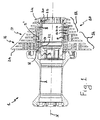
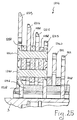
最初に図1を参照すると、自転車の後輪用のハブ1が、ハブ本体2およびフリーホイール本体3の部材(以下では、「フリーホイール本体」と称する)を有している。フリーホイール本体3は、任意の公知のシステム(図示されていない)を介してハブ本体2にカップリングされており、そのようなシステムによって、フリーホイール本体3は、回転軸Xを中心とする或る回転の方向において空回りをすることができ、反対の回転方向においてハブ本体2を引っ掛けることができる。
Referring first to FIG. 1, a
フリーホイール本体3は、ほぼ円筒形の形状を有しており、その外表面にいくつかの溝5が設けられている。
The
11枚のスプロケットを有するスプロケット・アセンブリ10が、溝5に係合されてフリーホイール本体3に取り付けられているのが好ましい。スプロケット・アセンブリ10は、互いに別個独立しているスプロケットのシリーズ12と、互いに拘束されたスプロケットのシリーズ14とを有している。
A
シリーズ12の別個独立しているスプロケットは、フリーホイール本体3に係合していない円筒形のスペーサ部材13によって互いに隔てられている。拘束されたスプロケットのシリーズ14は、横並びに配置されて、かつ、円筒形のスペーサ部材13によって隔てられた2つのスプロケット・セット16および17を含んでいる。
The
シリーズ12の別個独立しているスプロケットおよびシリーズ14の拘束されたスプロケットは、フリーホイール本体3に取り付けられるとき、フリーホイール本体3の軸方向の当接部材18に接触して行き止まり、フリーホイール本体3にねじ込まれるリングナット20によって保持される。
When the independent sprocket of the
スプロケット・アセンブリ10の最初のスプロケット(最も直径が大きいスプロケット)および最後のスプロケット(最も直径が小さいスプロケット)は、チェーン(図示されていない)との係合のための歯付きクラウン24との関係で軸方向にシフトされたフリーホイール本体3との係合部22を有している。スプロケット・アセンブリ10の最初のスプロケットの係合部22は、フリーホイール本体3の外側に向かって、すなわちリングナット20に向かって、さらに換言すればスプロケット・アセンブリ10の中央領域に向かって、軸方向にシフトされている。一方、スプロケット・アセンブリ10の最後のスプロケットの係合部22は、フリーホイール本体3の内側に向かって、すなわち軸方向の当接部材18に向かって、さらに換言すればスプロケット・アセンブリ10の中央領域に向かって、軸方向にシフトされている。
The first sprocket (the largest diameter sprocket) and the last sprocket (the smallest diameter sprocket) of the
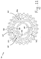
セット16が、図2および3によりよく示されており、回転軸Xの方向の両端に配置された2つの支持スプロケット25と、支持スプロケット25の間に配置された被支持スプロケット26とを有している。
The
支持スプロケット25は、最も半径方向内側の領域に配置された、フリーホイール本体との係合のための半径方向内側の環状部28を有しており、この部位28に、フリーホイール本体3との係合手段が備えられている。図2および3の例では、部位28に、フリーホイール本体3の溝5および溝5の間の歯にそれぞれカップリングする歯30および溝32が備えられている。歯30のうちの1つは、支持スプロケット25をただ1つの所定の位置でフリーホイール本体3に取り付けることができるよう、残りの歯とは異なる形状を有している。
The
さらに、支持スプロケット25は、半径方向内側の環状部28と同心であって自転車のチェーンとの係合のための歯を備えている半径方向外側の環状部34を有している。この部位34は、以下では「歯付きクラウン」とも称される。
In addition, the
環状の係合部28および歯付きクラウン34は、好ましくは放射状であって、「アーム」としても知られている接続部36によって一体に接続されている。アーム36は、軸Xからの半径方向の距離が異なるように配置された2つの孔38を有している。2つの支持スプロケット25の孔38が、軸方向に互いに整列しており、リベット40(または、ねじ、ボルト、ピンなどの他の固定部材)が、孔38に係合して2つの支持スプロケット25を互いに一体にしている。
The
さらに、2つの支持スプロケット25は、軸方向に互いに整列したそれぞれの追加の孔42を有しており、この孔に追加のリベット44が係合している。
In addition, the two
孔38および42は、同一であることが好ましく、大径の部位および小径の部位を有している。大径の部位が、リベット40および44の両自由端にそれぞれ形成される頭部46および48のための収容/支持領域を与えている。
The
図2および3の例では、3つの追加の孔42が存在しており、支持スプロケット25の半径方向外側の環状部34に位置する同じ仮想の円周上に等しい角度間隔で配置されている。また、3つのアーム36が存在し、互いに等しい角度間隔で配置されており、互いに約120°だけずらされ、追加の孔42に対して約60°だけずらされている。
In the example of FIGS. 2 and 3, three
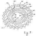
中間のスプロケット26は、セット16の一部の部品を省略している図7においてより明確に見て取ることができるが、フリーホイール本体3との係合部が存在しない点で、端にあるスプロケット25と相違している。さらに、このスプロケット26は、支持スプロケット25の最も半径方向外側の孔38および追加の孔42にちょうど整列するように構成された孔50を有している。このようにして、中間のスプロケット26が、最も半径方向外側のリベット40および追加のリベット44を介して、支持スプロケット25によって支持される。
The
したがって、図7の例では、6つの孔50が存在しており、約60°の等しい角度間隔で配置されている。
Accordingly, in the example of FIG. 7, there are six
孔50(したがって、孔50の整列相手である孔38および42も)は、すべて回転軸Xから同じ半径方向の距離に配置されている。そのような半径方向の距離が、チェーンを最も小径のスプロケット25に係合させることができるようにする必要があるため、下限を有していることに注意すべきである。そのような半径方向の距離は、好ましくは、最小の直径を有するスプロケット25において、歯付きクラウン34の外側端に形成される円周と、孔38および42の最大の半径方向の寸法に形成される円周との間の距離が最小になるように選択される。
The holes 50 (and therefore the
中間のスプロケット26は、54で示される、半径方向外側の歯付きの環状部、または歯付きクラウンを有している。孔50が、歯付きクラウン54の半径方向内周端部分から出発してスプロケット26の内側または中央領域に向かって片持ち梁状に延びる半径方向の突起52に形成されている。フリーホイール本体3との係合部を持たず、接続アームを持たず、半径方向内側の環状部も持たない真ん中のスプロケット26が、支持スプロケット25よりもはるかに軽量であることに注目すべきである。
The
セット16のスプロケット25および26は、スペーサ部材によって互いに所定の間隔に保たれている。前記スペーサ部材は、軸方向に支持(resting)を与え、リベット40および44の滑りを防止し、スプロケットを剛にしてチェーンの引張り作用に起因する曲げおよびねじり変形を防止している。
The
スペーサ部材は、より容易で、かつ費用対効果に優れた製造が可能になるようなさまざまな寸法および形状であってよい。とくに、図2〜4および7に示した例では、第1の円筒形のスペーサ部材56が、2つの支持スプロケット25の係合部28の間に配置されている。スペーサ部材56は、好ましくはフリーであり、すなわち、スプロケットに固定されていないが、係合部28の間の空間に挿入されていて、半径方向の寸法ゆえに係合部28の間から出ることができない。スペーサ部材56は、スペーサ部材56とスプロケット25との間の接触圧によっても保持されているのが好ましい。使用される材料は、圧縮に耐える任意の材料であることが好ましく、より好ましくは、ポリマー材料または強化プラスチック材料[すなわち構造材でない補強材(通常は、粉末、顆粒、または短繊維、すなわち5ミリメートル未満の寸法の繊維)が添加されたポリマー材料]である。
The spacer member may be of various sizes and shapes that allow for easier and more cost effective manufacturing. In particular, in the example shown in FIGS. 2 to 4 and 7, the first
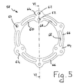
寸法および形状が同一である2つの環状のスペーサ部材58が、それぞれの支持スプロケット25と中間のスプロケット26との間に介装されており、セット16を最も小さい直径のスプロケット25を省略して示している図4、ならびに図5および6においてわかりやすく見て取ることができる。
Two
各スペーサ部材58は、ほぼ環状の本体60を有しており、本体60に、リベット40を通すための孔62が、支持スプロケット25の孔38および中間のスプロケット26の孔50に整列させて形成されており、追加のリベット44を通すための追加の孔63が、支持スプロケット25の追加の孔42および中間のスプロケット26の残りの孔50に整列させて形成されている。
Each
孔62は、半径方向に延びる複数の部位64に形成されているのが好ましい。とくに、ほぼ環状の本体60が、半径方向の寸法がより大きい3つの部位64を有している。このような部位64が、ブリッジ部66によって互いに接続されており、ブリッジ部66に、軽量化空洞68(好ましくは、くり抜きの形態で形成される)および追加の孔63が形成されている。各ブリッジ部66は、とくに、それぞれの追加の孔63に対して両側に配置された2つの軽量化空洞68を有している。
The
ブリッジ部66は、半径方向に延びる部位64の中央領域から出発し、周方向に延びている。
The
セット16において、支持スプロケット25が、異なる半径方向の距離に配置された複数のそれぞれの接触領域において、円筒形のスペーサ部材56および環状のスペーサ部材58を介して、中間のスプロケット26および他方の支持スプロケット25に当接する。とくに、支持スプロケット25の半径方向内側の環状部28が、円筒形のスペーサ部材56を介して互いに支持する一方で、支持スプロケット25のアーム36ならびに追加の孔42の周囲のカップリング領域が、2つの別々のスペーサ部材58の半径方向に延びる部位64ならびにこの2つのスペーサ部材58の孔63の周囲のカップリング領域を介して、両面において中間のスプロケット26の孔50の周囲のカップリング領域をそれぞれ支持する。第1の最も半径方向内側先端の支持点(a first most radially inner extreme resting point )56’(スペーサ56の半径方向内側の縁に位置する)から第2の先端の支持点(a second extreme resting point)58’(スペーサ58の半径方向外側の縁に位置する)まで、スプロケット間の半径方向の支持部の拡がりは、フリーホイール本体3への係合手段28によって形成される仮想の円周28’とセット16の最小のスプロケットの半径方向外側端部との間の半径方向の拡がりの1/3、好ましくは1/2、より好ましくは2/3に等しい。図2および3に見て取ることができるように、上記仮想の円周は、係合状態においてフリーホイール本体3の円筒形の外表面5’(図1)に接する環状部28の表面によって形成される。また、環状部28がフリーホイール本体の外表面に接しない技術的解決策も仮定できるが、この場合にも、上記仮想の円周は、環状部28に係合させられると考えられるフリーホイール本体の最大の外径に一致する。このようにして、高さhが、フリーホイール本体3から突き出しているスプロケット部分を常に表している。
In the
図示された例から見て取ることができるように、支持部の拡がりとは、半径方向における先端の支持点間の距離を意味する。なぜならば、これらの先端点の間で効果的な支持が不連続でありうるためである。 As can be seen from the illustrated example, the expansion of the support means the distance between the support points at the tip in the radial direction. This is because the effective support between these tip points can be discontinuous.
上述の内容から、セット16において、各スペーサ部材58が、複数の別個のカップリング部において支持スプロケット25に組み合わせられ、各スプロケットが、大きな半径方向の拡がりを有する接触領域においてスペーサ部材56および58を介して隣のスプロケットに当接することを見て取ることができる。このようにして、スペーサ部材58がスプロケットの構造的な補強部材として機能して、個々のスプロケットの構造強度の向上に寄与しているスプロケット・セットが形成される。
From the above, in the
さらに、スペーサ部材58は、スプロケットよりも軽量な材料で製作されるのが好ましく、セット16の重量が低く保たれる。このような構造的特性を備えるために、スペーサ部材58を、例えば軽金属合金あるいはポリマー材料のマトリックス中に構造繊維を有している複合材料で製作することができる。
Furthermore, the
典型的には、構造繊維は、カーボン繊維、ガラス繊維、アラミド繊維、セラミック繊維、ボロン繊維、ポリエステル繊維、およびこれらの組み合わせで構成されるグループから選択され、なかでもカーボン繊維が好ましい。 Typically, the structural fibers are selected from the group consisting of carbon fibers, glass fibers, aramid fibers, ceramic fibers, boron fibers, polyester fibers, and combinations thereof, with carbon fibers being preferred.
ポリマー材料中での前記構造繊維の配置は、構造繊維の断片または小片のランダム配置、繊維のほぼ1方向の規則的配置、繊維のほぼ2方向の規則的配置(例えば、横糸および縦糸による織成)、あるいは上記の組み合わせであってよい。 The arrangement of the structural fibers in the polymer material can be random arrangement of structural fiber fragments or pieces, regular arrangement of fibers in almost one direction, regular arrangement of fibers in almost two directions (for example, weaving with weft and warp yarns) ) Or a combination of the above.
マトリックスのポリマー材料は、熱硬化性であるのが好ましい。しかしながら、熱可塑性物質の使用の可能性を排除するものではない。マトリックスは、エポキシ樹脂を含んでいるのがさらに好ましい。 The matrix polymeric material is preferably thermosetting. However, this does not exclude the possibility of using thermoplastics. More preferably, the matrix includes an epoxy resin.
次に、図3および7を参照すると、2つの構造的なスペーサ部材58の間に、半径方向内側に位置する方のリベット40の周囲(したがって、孔38の周囲)に、小さな半径方向の寸法の円筒形のスペーサ・リング70が存在している。
3 and 7, between the two
円筒形のリング70およびスペーサ部材56は、軸方向の荷重に耐えることができる任意の材料から製作でき、例えば構造的なスペーサ部材58と同じ材料で製作してもよい。使用される材料は、ポリマー材料または強化プラスチック材料[すなわち構造材でない補強要素(通常は、粉末、顆粒、または短繊維、すなわち5ミリメートル未満の寸法の繊維)が添加されたポリマー材料]であるのが好ましい。
図8および9は、図1に示したスプロケット・アセンブリ10のセット17を示している。セット17は、セット16に比べてより小さな直径のスプロケットを有しており、支持スプロケット72がリベット74(あるいは、ねじ、ボルト、またはピンなどといった他の固定用の部材)を通すための孔73を、フリーホイール本体3とのカップリングのための半径方向内側の環状部78と歯付きクラウン80との間の接続アーム76にのみ有している点を主な点として、セット16と相違している。
8 and 9 show a
図8の例においては、5つのアーム76が存在している。さらに、全ての孔73が、回転軸Xから同じ半径方向の距離に配置されており、互いに等しい角度間隔で配置されている。
In the example of FIG. 8, there are five
支持スプロケット72の間に、セット16のスペーサ部材56とほぼ同一の環状のスペーサ部材82が介装される一方で、各支持スプロケット72と被支持の中間スプロケット86との間には、セット16の構造的なスペーサ部材58と同様の構造的なスペーサ部材88が介装されている(セット17から小径の支持スプロケット72が取り除かれている図10においてよりよく見て取ることができる)。構造的なスペーサ部材88が、リベット74などを通すための孔90(図10の例では、5つである)を有していること、およびそのような孔90の位置において、構造的なスペーサ部材88の半径方向の寸法が他の領域と比べて大きいことが、図10からとくに明らかである。
Between the
セット16の別の実施形態を以下に説明するが、説明において、構造的な観点で類似する要素、または機能的な観点で相当する要素は、これまでに割り当てた参照番号に100または100の倍数を加えることによって示されている。
Another embodiment of the
図11は、図2のセット16と同様のセット116を示しているが、最も小さな直径の支持スプロケットは省略されている(したがって、セット16の図4に示した部分と同様である)。セット116は、構造的なスペーサ部材158の形状においてのみ、セット16とは相違している。このスペーサ部材158においては、ブリッジ部166が、それぞれこぶを形成するように、半径方向に延びる部位164に周方向に接続されている。これにより、ブリッジ部166が一方のスプロケットと他方のスプロケットとの間(とくに、より直径の小さい2つのスプロケットの間)の空間を完全に塞ぐことがない空き領域167が、半径方向に延びる部位164に対する固定領域の付近に生み出され、スプロケット・アセンブリに堆積しうる泥または堆積物に軸方向および半径方向の両方の逃げ道が残される。
FIG. 11 shows a set 116 similar to the
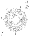
図12は、図2のセット16と同様のセット216を示しているが、やはり最も小さな直径の支持スプロケットは省略されている(したがって、セット16の図4に示した部分と同様である)。セット216は、構造的なスペーサ部材258の形状において、セット16とは相違している。とくに、それぞれのブリッジ部266が、半径方向に延びる部位264の半径方向外側の領域に結合され、2つの半径方向に延びる部位264の間を延びて、リングを形成している。そのようなリングは、ほぼ円形のクラウンの形状であって、ブリッジ部266が、延びる部位264によってのみ中断されており、延びる部位264の最も半径方向外側の領域に周方向に接続されている。したがって、半径方向に延びる部位264は、前記リングから半径方向内側へと片持ち梁状に延びている。
FIG. 12 shows a
図13は、図2のセット16と同様のセット316を示しているが、やはり最も小さな直径の支持スプロケットは省略されている(したがって、セット16の図4に示した部分と同様である)。セット316は、構造的なスペーサ部材358および最も半径方向内側のスペーサ部材356の両者の形状において、セット16とは相違している。
FIG. 13 shows a
構造的なスペーサ部材358は、ほぼ環状の物体であり、リベットまたは同様の固定用部材を通すための孔を、すべて軸Xから同じ半径方向の距離に配置している。最も半径方向内側のスペーサ部材356は、例えば円筒形であるほぼ環状の部位357を有しており、アーム359が環状の部位357から半径方向外側へと片持ち梁状に突き出しており、アーム359の末端に、支持スプロケット325(一方のみが示されている)を接合するリベット340または同様の固定用部材との係合のための孔342が形成されている。孔342の周囲のアーム359領域は、開口部343により軽量に形成されている。
The
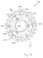
図14および15が、本発明による別のセットを示しており、そのセットは、416によって示されており、図13のセット316に類似している。詳しくは、図14が、そのようなセット416を最も小さな直径の支持スプロケットを省略して図示しており、したがって、図14は、セット316の図13に示されている部分と全く同様である。セット416が、構造的なスペーサ部材358と最も半径方向内側のスペーサ部材356とが、ただ1つのスペーサ部材455に融合されている点で、図13のセット316とは相違していることに注目すべきである。とくに、スペーサ部材455は、例えば円筒形であって2つの支持スプロケット425の間の空間を完全に占めるような寸法である半径方向内側の環状部456、ならびにそれぞれの支持スプロケット425と中間のスプロケット426との間に挿入されるよう、半径方向内側の環状部456から半径方向外側へと突き出しているフォーク状部458を有している。とくに、フォーク状部458は、半径方向外側に位置して軸方向において互いに面している1対のほぼ環状の部位458a、ならびに軸方向において互いに面し、それぞれ前記半径方向内側の環状部456と前記半径方向外側の環状の部位458aとの間を延びている複数の対のアーム458bを有している。図示の例では、3つの対のアーム458bが存在している。ほぼ環状の部位458aは、最大の半径方向寸法の円周に対する複数の凹所458cを、被支持スプロケット426をバヨネット式の動き(bayonet movement)によって収容できるような配置および寸法で有しており、すなわち、スプロケット426の半径方向の突起452を凹所458cに挿入し、次いでスプロケット426の孔450をスペーサ部材455の孔462および463に軸方向に整列する操作位置に回転させることによって、被支持スプロケット426を収容することができる。
14 and 15 show another set according to the present invention, which is indicated by 416 and is similar to the
この場合、スペーサ部材455を、例えば軽合金、あるいは構造繊維をポリマーマトリックス中に含む複合材料で製作することができる。また、半径方向内側の環状部456を、圧縮に耐える軽材料から製作し、構造的なフォーク状部458を、曲げおよびねじりに耐える軽材料から製作してもよい。例えば、半径方向内側の環状部456を実質的に構成する円筒形のアルミニウム製インサートを、フォーク状部458を構成する複合材料が注入される金型に入れて、共成型することが可能である。
In this case, the
図16は、構造的なスペーサ部材158が、図17に示されているようにそれぞれの自由端部において互いに結合されて全体としてほぼ環状の構造体560を形成する複数の接続部材558で置き換えられている点で、図11のセット116とは相違するセット516を示している。詳しくは、接続部材558は、孔563においてリベット544を介して互いに結合される。各ブリッジ部558が、リベット540のための孔562を形成できるように半径方向に効果的に延びる中央部564を有している。中央部564は、それぞれの支持スプロケット525(図16には一方のみが示されている)と中間のスプロケット526との間に挿入できるように、フォーク状の形状を有している。
FIG. 16 replaces the
延びる部位564から、2つの補強アーム566が円周方向に片持ち梁状に延びており、補強アーム566の端部に、リベット544を挿入するための孔563が形成されている。2つのアーム566は、平行であるが一致はしない円周の平面上を延びている。取り付けられた状態において、2つのアーム566の一方が、第1の支持スプロケット525と中央のスプロケット526との間に挿入される一方で、他方のアームが、他方の支持スプロケット525と中央のスプロケット526との間に挿入される。
Two reinforcing
図17から明らかであるとおり、この実施形態は、構造的なスペーサ部材が完全に環状である実施形態と比べて、円周領域において、補強アーム566が1つしか存在しないため、より軽量であるという利点を有している。
As is apparent from FIG. 17, this embodiment is lighter than the embodiment in which the structural spacer member is completely annular, since there is only one reinforcing
アーム566が、延びる部位564から広がるにあたって、延びる部位564の最も半径方向内側の領域から出発しているため、泥または他の不純物の通過を可能にする空き空間567がアーム566とスプロケット525、526との間に残される点に注目すべきである。これらの領域の下方における単一のアーム566の存在が、そのような通過を一層容易にしている。
As the
図18は、スプロケットを2つだけ有するセット616を示している。とくに、フリーホイール本体3との係合のための環状部628を備える第1の支持スプロケット625が、リベット640および追加のリベット644を介して第2のスプロケット626を片持ち梁状に支持している。2つのスプロケットの間には、リベット640のための1対の孔662を有している環状の構造的なスペーサ部材658、ならびに追加のリベット644の周りの円筒形のスペーサ・リング670が、それぞれ介装されている。フリーホイール本体3上に連続して取り付けられる2つのセット616の間に、円筒形のスペーサ部材656を介在させることができる。
FIG. 18 shows a
図19は、各支持スプロケット725が、図2のスプロケット25の3つのアーム36の代わりに、半径方向内側の環状部728と歯付きクラウン734との間に、6つの放射状の接続アーム736を有している点で、図2のセット16とは相違するセット716を示している。各接続アーム736が、リベット740を通すためのただ1つの孔762を有している。したがって、接続アーム736の外側の追加のリベットは不要である。各アーム736は、底辺を半径方向内側に向けた三角形の形状である。アームをより軽くするために、軽量化孔761または任意のタイプの形状を有する開口が、孔762の下方に設けられている。この場合、構造的なスペーサ部材758が、半径方向に延びる部位を持たない単純なリングである一方で、係合部728の間に、図3のスペーサ部材56のような円筒形のスペーサ部材が設けられている。
FIG. 19 shows that each
軽量化孔の代案として、図20は、接続アーム836が小さな寸法(例えば、孔762の直径とほぼ同じであり、場合によっては孔762の直径よりも小さい)の中央部836aを備えて形成されているセット816を示している。
As an alternative to a lighter hole, FIG. 20 is formed with a connecting
多数のアームを備える図19および20のような技術的解決策は、アームが少ない図2の様な技術的解決策に比べて重量が大きくなるが、より剛である。 A technical solution like that of FIGS. 19 and 20 with a large number of arms is heavier but more rigid than the technical solution like FIG. 2 with fewer arms.
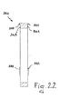
図21および22は、これまでの実施形態の円筒形のスペーサ部材56、156、256、356、456、556、656、756、856の代案として使用することができる、一変種の円筒形のスペーサ部材956を示している。とくに、円筒形のスペーサ部材956は、これまでの実施形態の半径方向内側の環状部28、128、228、328、428、528、628、728、828の1つに引っ掛けることができるフック歯955を有している。これらの係合歯955は、平坦な環状の壁949から軸方向に片持ち梁状に突き出しており、スペーサ部材956が2つの支持スプロケットの間に取り付けられたときに、スペーサ部材が係合部に対して半径方向に相対移動することがないようにしている。
21 and 22 show a variant of cylindrical spacer that can be used as an alternative to the
上述の係合歯955が3つ存在しているのが好ましい。この場合、上述の歯955は、互いに120°ずらされた角度で配置されている。
There are preferably three
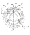
図23および24は、本発明による別のセット1016を示しており、どちらもフリーホイール本体との係合部1028を有している2つのスプロケット1025が、互いに接続されている。2つのスプロケット1025が、リベット1040および追加のリベット1044によって堅く拘束されており、リベット1040および追加のリベット1044は、構造的なスペーサ部材1058も一体構造で保持している。スペーサ部材が、スプロケット1025の2つの表面に面して、最小のスプロケット1025の高さの大部分にわたって支持している。とくに、支持高さHが、最小のスプロケット1025の高さh(すなわち、外径と内径との間の差の半分)の1/3と同じかそれよりも大きく、好ましくは高さhの1/2と同じかそれよりも大きく、さらに好ましくはhの2/3と同じかそれよりも大きい。
FIGS. 23 and 24 show another
図25は、4つのスプロケットを有するセット1216の断面図を示しており、とくに、2つの支持スプロケット1225が、セット1216の軸方向の両端に配置され、2つの中央スプロケット1226が、リベット1240を介して支持スプロケット1225によって支持されている。支持スプロケット1225のみが、フリーホイール本体3との係合部1228を有しており、係合部1228の間に円筒形のスペーサ部材1256が介装されている。構造的なスペーサ部材1258が、円筒形のスペーサ部材1256よりも半径方向外側の位置において、各対のスプロケットの間に配置され、リベット1240によってスプロケットそのものに拘束されている。
FIG. 25 shows a cross-sectional view of a
セット1216は、2つの別途のスプロケット1212と一緒にフリーホイール本体3に取り付けられている。
The
図示の例は、考えられるいくつかの構成を示したにすぎず、例えば、各セットのスプロケットの数は、最少の2から、スプロケット・アセンブリの全てのスプロケットを含むまで、さまざまであってよい。しかしながら、少数(好ましくは、2つまたは3つ)のスプロケットを備えるセットが、個々の自転車乗りまたは個々の道順の要件に合致するスプロケット・アセンブリを与えるように、異なるサイズのスプロケットを備えるセットと迅速に交換できるため好ましい。また、支持スプロケットは、必ずしも端部のスプロケットである必要はなく、すべての端部のスプロケットである必要はなく、あるいは端部のスプロケットだけである必要もない。 The illustrated example shows only a few possible configurations, for example, the number of sprockets in each set may vary from a minimum of 2 to including all the sprockets of the sprocket assembly. However, a set with a small number (preferably two or three) sprockets can be quickly compared with a set with different sized sprockets to provide a sprocket assembly that meets the requirements of individual bicyclists or individual routes. It is preferable because it can be replaced. Also, the support sprocket need not necessarily be an end sprocket, and need not be an end sprocket, or need only be an end sprocket.
図26および27は、フリーホイール本体との係合部1128とスプロケット1125、1126を支持するための放射状のアーム1164および1164aとを有するただ1つのスペーサ部材1156が設けられているアセンブリ1116を示しており、スプロケット1126が、最少の直径を有するスプロケットである。各スプロケット1125および1126が、短い半径方向のアーム1136および長い半径方向のアーム1136aを有している。長い半径方向のアーム1136aが、2つのスプロケットにきわめて広がった側面支持をもたらすために、放射状のアーム1164aの長さの大部分にわたり、好ましくは放射状のアーム1164aの長さのほぼ全体にわたって、放射状のアーム1164aを支持している。とくに、この支持は、アーム1164aの末端に一致する半径方向外側の点1195とアーム1136aの末端に一致する半径方向内側の点1196との間に拡がっている。点1195および1196の間の距離Hは、前記フリーホイール本体とのカップリングのための仮想の円周(前記フリーホイール本体との係合手段によって形成される)と最小のスプロケット1126の半径方向外側端部との間の半径方向の拡がりhの少なくとも1/3に等しいのが好ましく、より好ましくは、H>1/2 hであり、あるいは、H>2/3 hである。
FIGS. 26 and 27 illustrate an
図28は、全体が2010によって示され、本発明によるスプロケット・アセンブリの別の実施形態を示しており、スプロケットが外表面に溝2005を有するフリーホイール本体2003に取り付けられている
FIG. 28 shows another embodiment of a sprocket assembly according to the present invention, generally designated 2010, where the sprocket is attached to a
スプロケット・アセンブリ2010の各スプロケット2025は、半径方向内側の部位に、溝2005との係合のための歯2028を備えている。スプロケット2025は、環状のスペーサ部材2056によって隔てられているが、スペーサ部材2056は、溝2005に係合してはおらず、スプロケット2025にカップリング固定されていない。
Each
スプロケット・アセンブリ2010において、各セットがスペーサ部材2056と両側において前記スペーサ部材2056に当接した2つのスプロケット2025とを有する本発明による複数のスプロケット・セットを確認することができる。各スペーサ部材2056が、好ましくは前記フリーホイール本体2003とのカップリングのための仮想の円周(上述の溝2005の係合歯2028によって形成される)と前記隣接する2つのスプロケットのうちの最小の直径のスプロケット2025の半径方向の外側端部との間の半径方向の拡がりhの少なくとも1/3に等しい高さHにわたって、隣接する2つのスプロケット2025の対向する表面に支えられている。H>1/2 hであるのがより好ましく、H>
2/3 hであるのがさらに好ましい。
In the sprocket assembly 2010, a plurality of sprocket sets according to the present invention can be identified, each set having a
More preferably, it is 2/3 h.
図29は、本発明のスプロケット・セットの一部を示しており、スプロケット3025が、補強部材または構造的な強化部材としても機能するスペーサ部材3058に組み合わせられている。部材3058は、これまでに説明した構造的なスペーサ部材のうちの1つと同様に構成可能であるが、図29の例では、図4、5、および6のスペーサ部材58と同様に構成されている。
FIG. 29 shows a portion of the sprocket set of the present invention, wherein the
部材3058が、少なくとも2つの別個の点においてスプロケット3025に堅くカップリングされている。このようにして、部材3058が、スプロケット3025のための補強バーのように機能する。
部材3058は、好ましくは少なくとも1つの円周に沿って分布した複数のリベット3040(あるいは、ねじ、ボルト、またはピンなどといった他の取り付け部材)によってスプロケットにカップリングされているのが好ましく、そのような円周は、スプロケット3025の末端に近いのが好ましい(このやり方で、スプロケット3025が、動作時に曲げ応力によりさらされる領域において補強される)。図30は、図29のスプロケット3025および部材3058の組立体の直径断面図である。
図31および32は、互いに面するように配置された2つのスプロケット4025を接続する別の補強部材4058を示している。部材4058は、これまでに説明した構造的なスペーサ部材のうちの1つと同様に構成可能であるが、図31および32の例では、図4、5、および6のスペーサ部材58と同様に構成されている。
FIGS. 31 and 32 show another reinforcing member 4058 that connects two
部材4058が、複数の点4062においてスプロケット4025のうちの1つに堅くカップリングされ、複数の点4063において別のスプロケット4025に堅くカップリングされている。このようにして、部材4058が、スプロケット4025のための補強バーのように機能する。
Member 4058 is rigidly coupled to one of
部材4058が、好ましくは少なくとも1つの円周に沿って分布した複数のリベット4040(あるいは、ねじ、ボルト、またはピンなどといった他の取り付け部材)によって、最も大きい直径のスプロケット4025にカップリングされているのが好ましく、やはり好ましくは少なくとも1つの円周に沿って分布した複数のリベット4044(あるいは、ねじ、ボルト、またはピンなどといった他の取り付け部材)によって、最も小さい直径のスプロケット4025にカップリングされているのが好ましい。リベット4040および4044は、角度方向に離間した位置にあるのが好ましい。
Member 4058 is coupled to the
本発明の利点のなかでも、互いに拘束固定されたスプロケットの相互支持の効果が注目される。この効果のために、使用時にチェーンによって加えられるスプロケットの曲げおよびねじりに対する抵抗は、このスプロケットを堅く拘束して単一の構造単位を形成している隣のスプロケットにも依存することができる。この理由で、スプロケットの厚さを減らすことができ、したがって標準的な形式のフリーホイール本体に11枚以上のスプロケットを収容することさえ可能になる。例えば、スプロケットの厚さは、1〜2mmの間であってよい。さらに好ましくは、1.4〜1.7mmの間であってよい。 Among the advantages of the present invention, the effect of mutual support of the sprockets restrained and fixed to each other is noted. Because of this effect, the resistance to sprocket bending and twisting applied by the chain in use can also depend on neighboring sprockets that tightly constrain the sprocket to form a single structural unit. For this reason, the thickness of the sprocket can be reduced, so that it is even possible to accommodate more than 11 sprockets in a standard type freewheel body. For example, the sprocket thickness may be between 1 and 2 mm. More preferably, it may be between 1.4 and 1.7 mm.
隣接のスプロケットの効果による各スプロケットの構造強度の向上が、円筒形のスペーサ部材56、156、256、356、456、556、656、756、856、956および構造的なスペーサ部材58、158、258、358、458、558、658、758、858、1058(チェーンが係合しているスプロケットの曲げに起因する変形を、隣接するスプロケットへと分配して阻止できる離間手段として、スプロケットの間に介装される)への支持によってさらに有利になることが観察されている。
The increase in the structural strength of each sprocket due to the effect of adjacent sprockets is due to the
さらに、好ましくは歯付きクラウンの付近においてスプロケットに堅く拘束される構造的なスペーサ部材58、158、258、358、458、558、658、758、858、1058は、すでにそれ自身が、曲げおよびねじりに起因する変形に対してスプロケットを補強している。
Furthermore, the
当然ながら、当業者であれば、不測でかつ具体的要望を満足すべく、上述の自転車用スプロケット・セットについて多数の改良および変形を考えることができ、それらはすべて、いかなる場合も、特許請求の範囲によって規定される本発明の保護の範囲に包含される。 Of course, one of ordinary skill in the art will be able to conceive of numerous improvements and variations on the above-described bicycle sprocket set to meet unexpected and specific needs, all of which are in any case claimed. It is included in the scope of protection of the present invention defined by the scope.
Claims (84)
より小さな直径を有する少なくとも1つの第2のスプロケット、および
前記第1のスプロケットと前記少なくとも1つの第2のスプロケットとの間に動作可能に配置され、前記第1のスプロケットおよび前記少なくとも1つの第2のスプロケットに当接している1つ以上のスペーサ部材(56、58、82、88、258、356、455、656、658、956、1058、1156、1256、1258、2056、3058、4058)を有しており、
前記第1のスプロケット、前記少なくとも1つの第2のスプロケット、および前記1つ以上のスペーサ部材のうちの少なくとも1つが、自転車の後輪のハブ(1)のフリーホイール本体(3)との係合手段(22)を備えていて、
前記係合手段(22)が、前記フリーホイール本体(3)とのカップリングのための仮想の円周(28’)を有しており、前記第1のスプロケットが、長手回転軸(X)に対する第1の半径方向の距離に配置された少なくとも1つの第1の接触点(56’)において、前記1つ以上のスペーサ部材のうちの少なくとも1つを介して、前記少なくとも1つの第2のスプロケットに支えられている自転車の後輪用のスプロケット・セットにおいて、前記第1のスプロケットが、前記第1の半径方向の距離とは異なる前記長手回転軸(X)からの第2の半径方向の距離に形成された少なくとも1つの第2の接触点(58’)において、前記1つ以上のスペーサ部材のうちの少なくとも1つを介して、前記少なくとも1つの第2のスプロケットにさらに支えられており、
前記少なくとも1つの第1の接触点(56’)と前記少なくとも1つの第2の接触点(58’)との間の半径方向の距離(H)が、前記仮想の円周(28’)と前記少なくとも1つの第2のスプロケットの半径方向外側端部との間の半径方向の拡がり(h)の1/3に、少なくとも等しいことを特徴とするスプロケット・セット(16、17、116、216、316、416、516、616、716、816、1016、1116、1216)。 A first sprocket having a larger diameter;
At least one second sprocket having a smaller diameter, and operatively disposed between the first sprocket and the at least one second sprocket, the first sprocket and the at least one second sprocket. One or more spacer members (56, 58, 82, 88, 258, 356, 455, 656, 658, 956, 1058, 1156, 1256, 1258, 2056, 3058, 4058) And
At least one of the first sprocket, the at least one second sprocket, and the one or more spacer members is engaged with a freewheel body (3) of a hub (1) of a bicycle rear wheel. Means (22),
The engaging means (22) has a virtual circumference (28 ') for coupling with the freewheel body (3), and the first sprocket has a longitudinal rotation axis (X). At least one first contact point (56 ') disposed at a first radial distance to the at least one second through at least one of the one or more spacer members. In a sprocket set for a rear wheel of a bicycle supported by a sprocket, the first sprocket has a second radial direction from the longitudinal axis of rotation (X) that is different from the first radial distance. At least one second contact point (58 ') formed at a distance further supports the at least one second sprocket via at least one of the one or more spacer members. It is and,
A radial distance (H) between the at least one first contact point (56 ′) and the at least one second contact point (58 ′) is defined as the virtual circumference (28 ′). A set of sprockets (16, 17, 116, 216, characterized in that it is at least equal to 1/3 of the radial extent (h) between the radially outer ends of said at least one second sprocket. 316, 416, 516, 616, 716, 816, 1016, 1116, 1216).
より小さな直径を有する第1のスプロケット(26)、
前記第1のスプロケット(25)と前記のより小さな直径を有する第1のスプロケット(26)との間に配置された第1のスペーサ部材(58)、
前記のより小さな直径を有する第1のスプロケット(26)の直径よりも小さな直径を有する第2のスプロケット(25)、
前記のより小さな直径を有する第1のスプロケット(26)と前記の小さな直径を有する第2のスプロケット(25)との間に配置された第2のスペーサ部材(58)、ならびに前記第1のスプロケット(25)と前記の小さな直径を有する第2のスプロケット(25)との間に配置された第3のスペーサ部材(56)を有しており、
前記少なくとも1つの第1の接触点(56’)が、前記少なくとも1つの第3のスペーサ(56)に形成され、前記少なくとも1つの第2の接触点(58’)が、前記第1のスペーサ部材(58)および前記第2のスペーサ部材(58)に形成されているスプロケット・セット(16)。 In claim 19,
A first sprocket (26) having a smaller diameter,
A first spacer member (58) disposed between the first sprocket (25) and the first sprocket (26) having a smaller diameter;
A second sprocket (25) having a diameter smaller than the diameter of the first sprocket (26) having the smaller diameter;
A second spacer member (58) disposed between the first sprocket (26) having the smaller diameter and the second sprocket (25) having the smaller diameter, and the first sprocket; A third spacer member (56) disposed between (25) and the second sprocket (25) having the small diameter,
The at least one first contact point (56 ′) is formed in the at least one third spacer (56), and the at least one second contact point (58 ′) is the first spacer. A sprocket set (16) formed on the member (58) and the second spacer member (58).
第1の半径方向の距離に配置された、前記1つ以上のスペーサ部材のうちの少なくとも1つとの少なくとも1つの第1の接触点(56’)と、前記第1の半径方向の距離とは異なる第2の半径方向の距離に配置された、前記1つ以上のスペーサ部材のうちの少なくとも1つとの少なくとも1つの第2の接触点(58’)とを有しており、
前記少なくとも1つの第1の接触点(56’)と前記少なくとも1つの第2の接触点(58’)との間の半径方向の距離(H)が、前記仮想の円周(28’)と前記スプロケットの半径方向外側端部との間の半径方向拡がり(h)の1/3に、少なくとも等しいことを特徴とするスプロケット。 A sprocket (25, 72, 325, 425, 525, 625, 725, 1025, 1125, 1225, 3025, 4025) for a bicycle rear wheel sprocket assembly (10) comprising one or more spacer members ( 56, 58, 82, 88, 258, 356, 455, 656, 658, 956, 1058, 1156, 1256, 1258, 2056, 3058, 4058) while interposing another sprocket of the sprocket assembly. It is configured to be incorporated into an assembly, and comprises means (22) for engaging the freewheel body (3) of the hub (1) of the rear wheel of the bicycle, said engaging means (22) And a sprocket having a virtual circumference (28 ') for coupling with the freewheel body (3) In the ket
At least one first contact point (56 ′) with at least one of the one or more spacer members disposed at a first radial distance and the first radial distance; And at least one second contact point (58 ′) with at least one of the one or more spacer members disposed at a different second radial distance;
A radial distance (H) between the at least one first contact point (56 ′) and the at least one second contact point (58 ′) is defined as the virtual circumference (28 ′). Sprocket characterized in that it is at least equal to 1/3 of the radial extent (h) between it and the radially outer end.
第1の半径方向の距離に配置された、前記スプロケット・アセンブリ(10、2010)のスプロケットとの少なくとも1つの第1の接触点(56’)と、前記第1の半径方向の距離とは異なる第2の半径方向の距離に配置された、前記スプロケットとの少なくとも1つの第2の接触点(58’)とを有しており、
前記少なくとも1つの第1の接触点(56’)と前記少なくとも1つの第2の接触点(58’)との間の半径方向の距離(H)が、前記仮想の円周(28’)と前記スプロケットの半径方向外側端部との間の半径方向の拡がり(h)の1/3に少なくとも等しいことを特徴とするスペーサ部材。 A sprocket spacer member (58, 88, 258, 358, 455, 658, 1058, 1156, 1258, 2056, 3058, 4058) of a bicycle rear wheel sprocket assembly (10, 2010) The rear wheel hub (1) has a substantially annular main body (60) provided with engagement means (22) with the freewheel main body (3), and the engagement means (22) In a spacer member having a virtual circumference (28 ') for coupling with the wheel body (3),
At least one first contact point (56 ') with the sprocket of the sprocket assembly (10, 2010) disposed at a first radial distance is different from the first radial distance Having at least one second contact point (58 ') with the sprocket disposed at a second radial distance;
A radial distance (H) between the at least one first contact point (56 ′) and the at least one second contact point (58 ′) is defined as the virtual circumference (28 ′). Spacer member characterized in that it is at least equal to 1/3 of the radial extent (h) between the sprocket radial outer ends.
の本体(60)の前記半径方向外側の環状部(458)に形成されているスペーサ部材(
455)。 Spacer member (58) according to claim 56, wherein said at least one second contact point (58 ') is formed in said radially outer annular portion (458) of said generally annular body (60).
455).
前記少なくとも1つのスプロケットが、少なくとも1つの補強部材(58、88、258、356、455、588、658、1058、1258、3058、4058)にカップリング固定されている構造単位であって、
前記少なくとも1つの補強部材(58、88、258、356、455、558、658、1058、1258、3058、4058)が、少なくとも1つの第1のカップリング部(56’)および前記少なくとも1つの第1のカップリング部(56’)とは異なる少なくとも1つの第2のカップリング部(58’)において、前記少なくとも1つのスプロケット(25、72、325、425、525、625、1025、1225、3025、4025)にカップリング固定されている構造単位。 At least one sprocket has an engagement means (22) of the freewheel body of the hub (1) of a bicycle rear wheel (3) (25,72,325,425,525,62 5,1 02 5, 1 22 5, 3 025, 4025) in a structural unit for a bicycle sprocket assembly (10 )
The at least one sprocket is a structural unit coupled to at least one reinforcing member (58, 88, 258, 356, 455, 588, 658, 1058 , 1258 , 3 058, 4058) ,
The at least one reinforcing member (58, 88, 258, 356, 455, 558, 658, 1058, 1258, 3058, 4058) includes at least one first coupling portion (56 ′) and the at least one first. In at least one second coupling portion (58 ′) different from one coupling portion (56 ′), the at least one sprocket (25, 72, 325, 425, 525, 625, 1025, 1225, 3025) , 4025) .
)のスプロケットを収容できるように、フォーク状構成を有している構造単位。 According to claim 71, wherein the central portion (564), said sprocket assembly (10
A structural unit having a fork-like configuration so that a sprocket can be accommodated.
625、1025、1225、3025、4025)を有している構造単位。 Two sprockets according to any one of claims 63 to 72 , combined with said at least one reinforcing member (58 , 88 , 258 , 356 , 455, 558 , 658, 1058 , 1258, 3 058, 4058). ( 25, 72, 325, 425, 525,
625, 1025, 1225, 3025, 4025 ).
前記スプロケット・アセンブリ(10)の少なくとも1つのスプロケットとの少なくと
も1つの第1のカップリング部(56’)と、前記少なくとも1つのスプロケットとの少なくとも1つの第2のカップリング部(58’)とを有しており、
前記少なくとも1つの第2のカップリング部(58’)が、前記少なくとも1つの第1のカップリング部(56’)とは異なるであることを特徴とする補強部材。 Bicycle rear wheel sprocket assembly (10) sprocket reinforcement (58, 88) lacking the engagement (22) of the rear wheel hub (1) with the freewheel body (3). 258, 558, 658, 1058, 1258, 3058, 4058),
At least one first coupling part ( 56 ′ ) with at least one sprocket of the sprocket assembly (10) and at least one second coupling part ( 58 ′ ) with the at least one sprocket. Have
The reinforcing member, wherein the at least one second coupling part ( 58 ' ) is different from the at least one first coupling part ( 56' ).
658、1058、1258、3058、4058)。 79. Reinforcing member (58, 88, 258, 558 ) according to any one of claims 76 to 79 , which is substantially annular and functions in a radially outer annular portion of at least one sprocket .
658, 1058, 1258, 3058, 4058) .
前記少なくとも1つの第1のカップリング部(56’)および前記少なくとも1つの第2のカップリング部(58’)が、前記補強部材(558)の両自由端部に形成されている補強部材(558)。 According to any one of claims 7 6-8 0, the central portion of elongated (564), and two bridge portions of opposite extending from both sides cantilevered said central portion (564) and (566) Have
Reinforcing member in which the at least one first coupling part (56 ′) and the at least one second coupling part (58 ′) are formed at both free ends of the reinforcing member (558) ( 558).
Applications Claiming Priority (2)
| Application Number | Priority Date | Filing Date | Title |
|---|---|---|---|
| ITMI20071659 ITMI20071659A1 (en) | 2007-08-09 | 2007-08-09 | SPROCKET ASSEMBLY FOR A REAR BICYCLE WHEEL AND SPROCKET PACK INCLUDING SUCH ASSEMBLY |
| ITMI2007A001659 | 2007-08-09 |
Publications (3)
| Publication Number | Publication Date |
|---|---|
| JP2009062038A JP2009062038A (en) | 2009-03-26 |
| JP2009062038A5 JP2009062038A5 (en) | 2011-06-30 |
| JP5451997B2 true JP5451997B2 (en) | 2014-03-26 |
Family
ID=40299781
Family Applications (1)
| Application Number | Title | Priority Date | Filing Date |
|---|---|---|---|
| JP2008205178A Active JP5451997B2 (en) | 2007-08-09 | 2008-08-08 | Bicycle rear wheel sprocket set and sprocket assembly |
Country Status (7)
| Country | Link |
|---|---|
| US (1) | US8821330B2 (en) |
| EP (4) | EP2433856B1 (en) |
| JP (1) | JP5451997B2 (en) |
| CN (1) | CN101362502B (en) |
| IT (1) | ITMI20071659A1 (en) |
| RU (1) | RU2008132884A (en) |
| TW (1) | TWI443042B (en) |
Families Citing this family (47)
| Publication number | Priority date | Publication date | Assignee | Title |
|---|---|---|---|---|
| US8057338B2 (en) * | 2005-08-30 | 2011-11-15 | Shimano, Inc. | Bicycle sprocket apparatus with reinforcement between sprockets |
| ITMI20071658A1 (en) | 2007-08-09 | 2009-02-10 | Campagnolo Srl | PINION MODULE FOR A BICYCLE AND SPROCKET PACK INCLUDING THIS MODULE |
| ITMI20071661A1 (en) * | 2007-08-09 | 2009-02-10 | Campagnolo Srl | ASSEEME OF WHEELS TOOTHED FOR A BICYCLE |
| ITMI20071660A1 (en) * | 2007-08-09 | 2009-02-10 | Campagnolo Srl | MOTION BIKE TRANSMISSION SYSTEM |
| ITMI20071659A1 (en) | 2007-08-09 | 2009-02-10 | Campagnolo Srl | SPROCKET ASSEMBLY FOR A REAR BICYCLE WHEEL AND SPROCKET PACK INCLUDING SUCH ASSEMBLY |
| US8820192B2 (en) | 2009-04-29 | 2014-09-02 | Race Face Prerformance Products Inc. | Bicycle crank arm and insert therefore |
| DE102010027228B4 (en) | 2009-11-04 | 2021-12-09 | Sram Deutschland Gmbh | Multiple sprocket arrangement for bicycles |
| US8852041B2 (en) * | 2010-09-30 | 2014-10-07 | Shimano, Inc. | Bicycle derailleur with rotation resistance |
| US8696503B2 (en) * | 2011-03-01 | 2014-04-15 | Shimano Inc. | Bicycle sprocket assembly |
| DE102011103489A1 (en) * | 2011-06-03 | 2012-12-06 | Sram Deutschland Gmbh | Multiple sprocket assembly for a bicycle transmission and rear wheel axle assembly with such a multiple sprocket assembly |
| TWI585000B (en) * | 2011-07-13 | 2017-06-01 | Sram De Gmbh | A multi-sprocket equipped with a small sprocket is used for the transmission of the bicycle transmission |
| US10221887B2 (en) | 2012-12-06 | 2019-03-05 | The Hive Global, Inc | Self locking bearing preload adjuster |
| US9533735B2 (en) * | 2013-07-19 | 2017-01-03 | Sram Deutschland Gmbh | Multiple-sprocket arrangement for a bicycle gearing |
| US9415835B2 (en) * | 2014-01-24 | 2016-08-16 | Shimano Inc. | Rotatable annular bicycle component and bicycle rear sprocket |
| TW201601971A (en) * | 2014-07-15 | 2016-01-16 | Tien Hsin Industries Co Ltd | Method of manufacturing sprocket set of bicycle |
| EP3037336B1 (en) * | 2014-12-23 | 2017-04-12 | Campagnolo S.R.L. | Sprocket assembly for a bicycle |
| US9403578B1 (en) * | 2015-02-05 | 2016-08-02 | Shimano Inc. | Bicycle sprocket assembly and bicycle rear sprocket assembly |
| DE102015203709A1 (en) * | 2015-03-02 | 2016-09-08 | Sram Deutschland Gmbh | Pinion arrangement with adapter |
| US10562588B2 (en) | 2015-09-01 | 2020-02-18 | The Hive Global, Inc | Bicycle cassette with locking connection |
| ITUB20154794A1 (en) * | 2015-11-06 | 2017-05-06 | Campagnolo Srl | Bicycle chain and motion transmission system comprising this chain |
| US11142280B2 (en) | 2016-03-24 | 2021-10-12 | The Hive Global, Inc. | Bicycle crank with spindle attachment structure |
| TWI731062B (en) | 2016-04-11 | 2021-06-21 | 美商福克斯製造有限公司 | Bicycle front sprocket |
| US10093388B2 (en) * | 2016-06-28 | 2018-10-09 | Shimano Inc. | Bicycle rear sprocket assembly |
| US10053187B2 (en) * | 2016-07-07 | 2018-08-21 | Shimano Inc. | Bicycle rear sprocket assembly and bicycle rear sprocket |
| US9868491B1 (en) * | 2016-07-21 | 2018-01-16 | Shimano Inc. | Bicycle sprocket assembly |
| US10377445B2 (en) * | 2016-09-20 | 2019-08-13 | Shimano Inc. | Bicycle front sprocket assembly |
| US20180194431A1 (en) * | 2017-01-06 | 2018-07-12 | Shimano Inc. | Bicycle sprocket, sprocket assembly, rear sprocket assembly, and drive train of bicycle |
| US11364971B2 (en) * | 2017-07-31 | 2022-06-21 | Shimano Inc. | Bicycle sprocket assembly and bicycle drive train |
| US10584786B2 (en) * | 2017-03-29 | 2020-03-10 | Shimano Inc. | Bicycle sprocket assembly |
| US10773772B2 (en) * | 2017-04-12 | 2020-09-15 | Shimano Inc. | Bicycle sprocket assembly |
| US11014628B2 (en) | 2017-04-28 | 2021-05-25 | Fox Factory, Inc. | Cinch direct mount 2X ring system |
| US10625820B2 (en) * | 2018-01-24 | 2020-04-21 | Shimano Inc. | Bicycle rear sprocket assembly |
| US10889353B2 (en) * | 2018-01-24 | 2021-01-12 | Shimano Inc. | Bicycle rear sprocket assembly |
| US11351815B2 (en) | 2017-08-21 | 2022-06-07 | The Hive Global, Inc. | Bicycle cassette with clamping connection |
| US10926836B2 (en) * | 2017-08-24 | 2021-02-23 | Shimano Inc. | Bicycle rear sprocket assembly |
| DE102017008074A1 (en) * | 2017-08-28 | 2019-02-28 | Sram Deutschland Gmbh | Sprocket carrier and multiple sprocket assembly |
| IT201700115407A1 (en) | 2017-10-13 | 2019-04-13 | Campagnolo Srl | Sprocket and bodice for mounting on a bicycle rear wheel hub |
| IT201700115411A1 (en) * | 2017-10-13 | 2019-04-13 | Campagnolo Srl | Bodice for a rear wheel hub of a bicycle and sprocket set suitable for being mounted on the hub by means of this body |
| CN108001605A (en) * | 2017-10-31 | 2018-05-08 | 天津市东陆自行车有限公司 | A kind of bicycle wheel disc |
| US11305837B2 (en) * | 2017-10-31 | 2022-04-19 | Shimano Inc. | Bicycle rear sprocket assembly |
| US11148753B2 (en) * | 2017-12-20 | 2021-10-19 | Sram, Llc | Sprocket assembly |
| US11359709B2 (en) | 2018-12-18 | 2022-06-14 | Fox Factory, Inc. | Chainring |
| US11680633B2 (en) | 2019-02-08 | 2023-06-20 | Fox Factory, Inc. | Chainring |
| US11591043B2 (en) * | 2019-07-30 | 2023-02-28 | Campagnolo S.R.L. | Sprocket-carrying body and sub-assembly of sprocket-carrying body and cogset for a bicycle rear wheel |
| IT201900013287A1 (en) | 2019-07-30 | 2021-01-30 | Campagnolo Srl | Adapter for a sprocket body for a bicycle rear wheel |
| US11932351B2 (en) | 2020-07-17 | 2024-03-19 | The Hive Global, Inc. | Conical bicycle cassette sprocket structure |
| US11767080B1 (en) * | 2022-07-15 | 2023-09-26 | Shimano Inc. | Rear sprocket assembly |
Family Cites Families (42)
| Publication number | Priority date | Publication date | Assignee | Title |
|---|---|---|---|---|
| FR910359A (en) | 1944-11-17 | 1946-06-05 | Forges Du Lignon | Improvement in freewheels of multi-gear bicycles |
| FR989114A (en) | 1949-06-21 | 1951-09-05 | Vandevoir | Method and device for driving an auxiliary motor bicycle |
| US3082637A (en) * | 1961-10-17 | 1963-03-26 | Gen Nailing Mach | Quick-change sprocket |
| US4102215A (en) | 1976-05-19 | 1978-07-25 | Shimano Industrial Company Limited | Multi-speed freewheel for a bicycle |
| JPS5436429Y2 (en) * | 1976-05-19 | 1979-11-02 | ||
| JPS52154853A (en) | 1976-06-18 | 1977-12-22 | Osaka Soda Co Ltd | Crosslinking of chlorinated polyethylene |
| JPS5742153Y2 (en) * | 1978-12-12 | 1982-09-16 | ||
| US4311914A (en) | 1978-12-18 | 1982-01-19 | Gretag Aktiengesellschaft | Process for assessing the quality of a printed product |
| US5026329A (en) * | 1990-08-02 | 1991-06-25 | Catepillar Inc. | Isolated drive sprocket assembly |
| EP0561380B1 (en) | 1992-03-18 | 1998-06-03 | Mannesmann Sachs Aktiengesellschaft | A chain driving mechanism with a bicycle or the like |
| DE4401272C1 (en) * | 1994-01-18 | 1995-03-16 | Fichtel & Sachs Ag | Multiple sprocket for bicycle derailleurs |
| US5766106A (en) | 1995-09-08 | 1998-06-16 | Edwards; Craig H. | Crankset assembly |
| JP3562883B2 (en) | 1995-09-29 | 2004-09-08 | 株式会社シマノ | Multi-stage wheels for bicycle rear wheels |
| DE29623258U1 (en) | 1996-07-23 | 1998-01-22 | Mannesmann Sachs Ag | Chain drive for bicycles |
| DE19629602A1 (en) | 1996-07-23 | 1998-01-15 | Mannesmann Sachs Ag | Chain drive with at least one chain wheel set for bicycles |
| US5954604A (en) | 1996-11-21 | 1999-09-21 | Shimano, Inc. | Multiple sprocket assembly for a bicycle |
| IT1289715B1 (en) | 1996-12-05 | 1998-10-16 | Campagnolo Srl | PINION SUPPORT GROUP FOR A BICYCLE |
| US6102281A (en) | 1997-11-13 | 2000-08-15 | Graphic Packaging Corporation | Partially-shield microwave heating tray |
| US6264575B1 (en) * | 1999-04-08 | 2001-07-24 | Shimano, Inc. | Freewheel for a bicycle |
| US6428437B1 (en) * | 1999-06-10 | 2002-08-06 | Raphael Schlanger | Power transmission assembly |
| US6382381B1 (en) | 2000-09-06 | 2002-05-07 | Shimano Inc. | Bicycle hub assembly |
| US7011592B2 (en) | 2002-03-08 | 2006-03-14 | Shimano, Inc. | Sprocket assembly for a bicycle |
| TW590954B (en) | 2002-05-09 | 2004-06-11 | Hwa-Yong Yin | Auto-controlling device for transmission chain engaging location of a multi-shift derailleur sprocket of a bicycle |
| DE10260565B4 (en) | 2002-12-21 | 2016-09-15 | Sram Deutschland Gmbh | The sprocket assembly |
| US7118505B2 (en) * | 2003-10-24 | 2006-10-10 | Cheng Ming Lee | Integrally formed gear set with a plurality of gears |
| JP2005238979A (en) | 2004-02-26 | 2005-09-08 | Shimano Inc | Rear derailleur for bicycle |
| US20060063624A1 (en) | 2004-09-20 | 2006-03-23 | Darrell Voss | Transmission systems and methods |
| DE202004019270U1 (en) * | 2004-12-13 | 2005-04-28 | Lee, Cheng Ming | Lightweight multiple sprocket wheel for gearchange mechanism on bicycle is of stepped dished shape with short cylinder sections with teeth joining annular sections, all made in one piece |
| US7585240B2 (en) * | 2005-02-03 | 2009-09-08 | Shimano Inc. | Bicycle sprocket assembly |
| EP1712811A1 (en) | 2005-04-15 | 2006-10-18 | Campagnolo S.R.L. | One-way transmission device for a hub of a rear wheel of a bicycle, pawl carrying body for such device and hub comprising such device |
| TWM274314U (en) | 2005-04-25 | 2005-09-01 | Jr-Bin Liou | Transmission structure for gearshift bicycle |
| US7435197B2 (en) * | 2005-05-11 | 2008-10-14 | Shimano Inc. | Rear sprocket for bicycle transmission |
| US8057338B2 (en) * | 2005-08-30 | 2011-11-15 | Shimano, Inc. | Bicycle sprocket apparatus with reinforcement between sprockets |
| US7824287B2 (en) | 2005-12-02 | 2010-11-02 | Shimano Inc. | Bicycle sprocket |
| US20080004143A1 (en) * | 2006-06-16 | 2008-01-03 | Shimano Inc. | Bicycle sprocket assembly |
| US7854673B2 (en) * | 2006-08-31 | 2010-12-21 | Shimano Inc. | Bicycle sprocket assembly having a reinforcement member coupled between sprockets |
| JP2008189254A (en) | 2007-02-07 | 2008-08-21 | Shimano Inc | Rear sprocket assembly for bicycle, and sprocket |
| ITMI20071659A1 (en) | 2007-08-09 | 2009-02-10 | Campagnolo Srl | SPROCKET ASSEMBLY FOR A REAR BICYCLE WHEEL AND SPROCKET PACK INCLUDING SUCH ASSEMBLY |
| ITMI20071658A1 (en) | 2007-08-09 | 2009-02-10 | Campagnolo Srl | PINION MODULE FOR A BICYCLE AND SPROCKET PACK INCLUDING THIS MODULE |
| ITMI20071661A1 (en) | 2007-08-09 | 2009-02-10 | Campagnolo Srl | ASSEEME OF WHEELS TOOTHED FOR A BICYCLE |
| US7871347B2 (en) * | 2007-10-11 | 2011-01-18 | Shimano Inc. | Bicycle rear sprocket assembly |
| US9376165B2 (en) * | 2009-10-16 | 2016-06-28 | Shimano Inc. | Bicycle sprocket |
-
2007
- 2007-08-09 IT ITMI20071659 patent/ITMI20071659A1/en unknown
-
2008
- 2008-03-28 EP EP11008763.2A patent/EP2433856B1/en active Active
- 2008-03-28 EP EP11008776.4A patent/EP2431271B1/en active Active
- 2008-03-28 EP EP11008777.2A patent/EP2441656B1/en active Active
- 2008-03-28 EP EP20080005988 patent/EP2042422B1/en active Active
- 2008-07-31 TW TW97129118A patent/TWI443042B/en active
- 2008-08-07 US US12/187,603 patent/US8821330B2/en active Active
- 2008-08-08 JP JP2008205178A patent/JP5451997B2/en active Active
- 2008-08-08 RU RU2008132884/11A patent/RU2008132884A/en not_active Application Discontinuation
- 2008-08-11 CN CN 200810210257 patent/CN101362502B/en active Active
Also Published As
| Publication number | Publication date |
|---|---|
| EP2042422A2 (en) | 2009-04-01 |
| JP2009062038A (en) | 2009-03-26 |
| EP2433856B1 (en) | 2014-10-01 |
| EP2431271B1 (en) | 2015-01-28 |
| EP2042422A3 (en) | 2009-08-26 |
| US20090042681A1 (en) | 2009-02-12 |
| EP2431271A1 (en) | 2012-03-21 |
| EP2441656B1 (en) | 2015-10-28 |
| ITMI20071659A1 (en) | 2009-02-10 |
| TWI443042B (en) | 2014-07-01 |
| EP2433856A1 (en) | 2012-03-28 |
| TW200911625A (en) | 2009-03-16 |
| RU2008132884A (en) | 2010-02-20 |
| CN101362502A (en) | 2009-02-11 |
| CN101362502B (en) | 2013-04-03 |
| EP2042422B1 (en) | 2013-12-25 |
| US8821330B2 (en) | 2014-09-02 |
| EP2441656A1 (en) | 2012-04-18 |
Similar Documents
| Publication | Publication Date | Title |
|---|---|---|
| JP5451997B2 (en) | Bicycle rear wheel sprocket set and sprocket assembly | |
| JP5623011B2 (en) | Bicycle sprocket module and sprocket assembly | |
| JP5726838B2 (en) | Bicycle right crank arm assembly and its crank arm and front sprocket | |
| JP5183999B2 (en) | Bicycle right crank arm assembly and its crank arm |
Legal Events
| Date | Code | Title | Description |
|---|---|---|---|
| A521 | Request for written amendment filed |
Free format text: JAPANESE INTERMEDIATE CODE: A523 Effective date: 20110511 |
|
| A621 | Written request for application examination |
Free format text: JAPANESE INTERMEDIATE CODE: A621 Effective date: 20110511 |
|
| A977 | Report on retrieval |
Free format text: JAPANESE INTERMEDIATE CODE: A971007 Effective date: 20121206 |
|
| A131 | Notification of reasons for refusal |
Free format text: JAPANESE INTERMEDIATE CODE: A131 Effective date: 20130312 |
|
| A521 | Request for written amendment filed |
Free format text: JAPANESE INTERMEDIATE CODE: A523 Effective date: 20130610 |
|
| A131 | Notification of reasons for refusal |
Free format text: JAPANESE INTERMEDIATE CODE: A131 Effective date: 20130813 |
|
| A521 | Request for written amendment filed |
Free format text: JAPANESE INTERMEDIATE CODE: A523 Effective date: 20131111 |
|
| TRDD | Decision of grant or rejection written | ||
| A01 | Written decision to grant a patent or to grant a registration (utility model) |
Free format text: JAPANESE INTERMEDIATE CODE: A01 Effective date: 20131210 |
|
| A61 | First payment of annual fees (during grant procedure) |
Free format text: JAPANESE INTERMEDIATE CODE: A61 Effective date: 20131227 |
|
| R150 | Certificate of patent or registration of utility model |
Ref document number: 5451997 Country of ref document: JP Free format text: JAPANESE INTERMEDIATE CODE: R150 Free format text: JAPANESE INTERMEDIATE CODE: R150 |
|
| R250 | Receipt of annual fees |
Free format text: JAPANESE INTERMEDIATE CODE: R250 |
|
| R250 | Receipt of annual fees |
Free format text: JAPANESE INTERMEDIATE CODE: R250 |
|
| R250 | Receipt of annual fees |
Free format text: JAPANESE INTERMEDIATE CODE: R250 |
|
| R250 | Receipt of annual fees |
Free format text: JAPANESE INTERMEDIATE CODE: R250 |
|
| R250 | Receipt of annual fees |
Free format text: JAPANESE INTERMEDIATE CODE: R250 |
|
| R250 | Receipt of annual fees |
Free format text: JAPANESE INTERMEDIATE CODE: R250 |
|
| R250 | Receipt of annual fees |
Free format text: JAPANESE INTERMEDIATE CODE: R250 |
|
| R250 | Receipt of annual fees |
Free format text: JAPANESE INTERMEDIATE CODE: R250 |