JP5451076B2 - Electromagnetic tracking method and apparatus for metal artifact compensation using a modular array of reference sensors. - Google Patents
Electromagnetic tracking method and apparatus for metal artifact compensation using a modular array of reference sensors. Download PDFInfo
- Publication number
- JP5451076B2 JP5451076B2 JP2008545213A JP2008545213A JP5451076B2 JP 5451076 B2 JP5451076 B2 JP 5451076B2 JP 2008545213 A JP2008545213 A JP 2008545213A JP 2008545213 A JP2008545213 A JP 2008545213A JP 5451076 B2 JP5451076 B2 JP 5451076B2
- Authority
- JP
- Japan
- Prior art keywords
- array
- reference sensors
- electromagnetic field
- sensors
- modular
- Prior art date
- Legal status (The legal status is an assumption and is not a legal conclusion. Google has not performed a legal analysis and makes no representation as to the accuracy of the status listed.)
- Expired - Fee Related
Links
- 239000002184 metal Substances 0.000 title claims abstract description 24
- 238000000034 method Methods 0.000 title claims abstract description 21
- 230000007246 mechanism Effects 0.000 claims abstract description 56
- 230000005672 electromagnetic field Effects 0.000 claims abstract description 55
- 230000004044 response Effects 0.000 claims abstract description 14
- 230000005284 excitation Effects 0.000 claims abstract description 5
- 238000003491 array Methods 0.000 claims description 16
- 239000007769 metal material Substances 0.000 claims description 8
- 210000001015 abdomen Anatomy 0.000 claims description 6
- 230000003287 optical effect Effects 0.000 claims description 5
- 210000000038 chest Anatomy 0.000 claims description 4
- 230000002093 peripheral effect Effects 0.000 claims description 4
- 238000010586 diagram Methods 0.000 description 16
- 239000002131 composite material Substances 0.000 description 7
- 238000005259 measurement Methods 0.000 description 6
- 230000005291 magnetic effect Effects 0.000 description 4
- 238000001574 biopsy Methods 0.000 description 3
- 238000003384 imaging method Methods 0.000 description 3
- 238000012317 liver biopsy Methods 0.000 description 3
- 206010028980 Neoplasm Diseases 0.000 description 2
- 230000008901 benefit Effects 0.000 description 2
- 230000004048 modification Effects 0.000 description 2
- 238000012986 modification Methods 0.000 description 2
- 206010019695 Hepatic neoplasm Diseases 0.000 description 1
- 210000003484 anatomy Anatomy 0.000 description 1
- 230000015572 biosynthetic process Effects 0.000 description 1
- 210000004556 brain Anatomy 0.000 description 1
- 230000010109 chemoembolization Effects 0.000 description 1
- 230000000295 complement effect Effects 0.000 description 1
- 230000008878 coupling Effects 0.000 description 1
- 238000010168 coupling process Methods 0.000 description 1
- 238000005859 coupling reaction Methods 0.000 description 1
- 230000001419 dependent effect Effects 0.000 description 1
- 238000005516 engineering process Methods 0.000 description 1
- 230000005294 ferromagnetic effect Effects 0.000 description 1
- 210000002216 heart Anatomy 0.000 description 1
- 239000007943 implant Substances 0.000 description 1
- 210000004185 liver Anatomy 0.000 description 1
- 208000014018 liver neoplasm Diseases 0.000 description 1
- 230000004807 localization Effects 0.000 description 1
- 238000004519 manufacturing process Methods 0.000 description 1
- 238000012634 optical imaging Methods 0.000 description 1
- 210000000056 organ Anatomy 0.000 description 1
- 238000000053 physical method Methods 0.000 description 1
- 210000002307 prostate Anatomy 0.000 description 1
- 238000007674 radiofrequency ablation Methods 0.000 description 1
- 238000001959 radiotherapy Methods 0.000 description 1
- 238000012154 short term therapy Methods 0.000 description 1
- 238000002603 single-photon emission computed tomography Methods 0.000 description 1
- 230000008685 targeting Effects 0.000 description 1
- 238000002560 therapeutic procedure Methods 0.000 description 1
- 230000009466 transformation Effects 0.000 description 1
- 238000002604 ultrasonography Methods 0.000 description 1
Images


Classifications
-
- A—HUMAN NECESSITIES
- A61—MEDICAL OR VETERINARY SCIENCE; HYGIENE
- A61B—DIAGNOSIS; SURGERY; IDENTIFICATION
- A61B5/00—Measuring for diagnostic purposes; Identification of persons
- A61B5/06—Devices, other than using radiation, for detecting or locating foreign bodies ; determining position of probes within or on the body of the patient
- A61B5/061—Determining position of a probe within the body employing means separate from the probe, e.g. sensing internal probe position employing impedance electrodes on the surface of the body
- A61B5/062—Determining position of a probe within the body employing means separate from the probe, e.g. sensing internal probe position employing impedance electrodes on the surface of the body using magnetic field
-
- A—HUMAN NECESSITIES
- A61—MEDICAL OR VETERINARY SCIENCE; HYGIENE
- A61B—DIAGNOSIS; SURGERY; IDENTIFICATION
- A61B2562/00—Details of sensors; Constructional details of sensor housings or probes; Accessories for sensors
- A61B2562/04—Arrangements of multiple sensors of the same type
- A61B2562/046—Arrangements of multiple sensors of the same type in a matrix array
-
- A—HUMAN NECESSITIES
- A61—MEDICAL OR VETERINARY SCIENCE; HYGIENE
- A61B—DIAGNOSIS; SURGERY; IDENTIFICATION
- A61B2562/00—Details of sensors; Constructional details of sensor housings or probes; Accessories for sensors
- A61B2562/16—Details of sensor housings or probes; Details of structural supports for sensors
- A61B2562/164—Details of sensor housings or probes; Details of structural supports for sensors the sensor is mounted in or on a conformable substrate or carrier
Landscapes
- Health & Medical Sciences (AREA)
- Life Sciences & Earth Sciences (AREA)
- Engineering & Computer Science (AREA)
- Heart & Thoracic Surgery (AREA)
- Molecular Biology (AREA)
- Biophysics (AREA)
- Pathology (AREA)
- Biomedical Technology (AREA)
- Human Computer Interaction (AREA)
- Medical Informatics (AREA)
- Physics & Mathematics (AREA)
- Surgery (AREA)
- Animal Behavior & Ethology (AREA)
- General Health & Medical Sciences (AREA)
- Public Health (AREA)
- Veterinary Medicine (AREA)
- Apparatus For Radiation Diagnosis (AREA)
- Magnetic Resonance Imaging Apparatus (AREA)
Abstract
Description
本発明の実施形態は電磁的な追跡の方法および装置に、より詳細には、参照センサー(reference sensor)のモジュラー・アレイ(modular array)を使った金属アーチファクト補償のための電磁的追跡(tracking)の方法および装置に関する。 Embodiments of the present invention provide a method and apparatus for electromagnetic tracking, and more particularly, electromagnetic tracking for metal artifact compensation using a modular array of reference sensors. Relates to the method and apparatus.
画像ガイダンスは、低侵襲の医療手順の結果を改善するために日常的に使われている。撮像が医師に患者の解剖構造中へのビューを与える。針およびカテーテルの位置が、解剖学的または機能的画像との関係で示され、それにより医師が処置をより迅速かつ精確に目標に合わせるのを助けることができる。 Image guidance is routinely used to improve the results of minimally invasive medical procedures. Imaging gives the physician a view into the patient's anatomy. The position of the needle and catheter is shown in relation to anatomical or functional images, which can help the physician to target the procedure more quickly and accurately.
電磁的追跡システム(EMTS: electromagnetic tracking systems)は、介入の部位のまわりに小さな磁場を確立することによってオブジェクトを位置特定するために使われる。EMTS技術は、皮膚を通して生検針を肝腫瘍に挿入するといった非視線(non-line-of-sight)用途に好適である。特に、経皮的な肝生検は、針が皮膚を通じて挿入され、腫瘍の位置を目標とされることを要求する。医師はCTデータを、手順をガイドするための解剖学的なロードマップとして使うことができる。手順の間、生検針の位置が画像に重ね合わされ、それにより医師が腫瘍に向かって操縦するのを助けることができる。 Electromagnetic tracking systems (EMTS) are used to locate objects by establishing a small magnetic field around the site of intervention. EMTS technology is suitable for non-line-of-sight applications such as inserting a biopsy needle through the skin into a liver tumor. In particular, percutaneous liver biopsy requires a needle to be inserted through the skin and targeted to the location of the tumor. Doctors can use CT data as an anatomical roadmap to guide the procedure. During the procedure, the position of the biopsy needle is superimposed on the image, which can help the physician to steer towards the tumor.
針の先端は、腹に埋め込まれているときは見えないので、針の位置を追跡するために電磁的追跡システム(EMTS)が使われる。簡単なEMTSは、場発生器およびセンサー・コイルからなる。コイルは針の先端に位置され、そこで、場発生器によって生成された磁場を測定する。この測定は、その針の、場発生器に対する空間的な位置を与える。 Since the needle tip is not visible when implanted in the abdomen, an electromagnetic tracking system (EMTS) is used to track the position of the needle. A simple EMTS consists of a field generator and a sensor coil. The coil is located at the tip of the needle, where it measures the magnetic field generated by the field generator. This measurement gives the spatial position of the needle with respect to the field generator.
残念ながら、金属オブジェクトはEMTS場をゆがめ、それによりセンサーの位置および配向の測定精度を限定する。金属アーチファクトは、患者台、撮像システムまたは医療器具から生じうる。特に、強磁性および伝導性の金属オブジェクトはEMTS場発生器によって生成された磁場をゆがめる。ゆがみはセンサー・コイルによってなされる測定に影響し、それによりセンサーの位置および配向の測定精度を限定する。 Unfortunately, metal objects distort the EMTS field, thereby limiting the accuracy of sensor position and orientation measurements. Metal artifacts can arise from patient tables, imaging systems or medical instruments. In particular, ferromagnetic and conductive metal objects distort the magnetic field generated by the EMTS field generator. Distortion affects the measurements made by the sensor coil, thereby limiting the accuracy of sensor position and orientation measurement.
したがって、当技術分野における問題を克服するための改良された方法およびシステムが望まれている。 Accordingly, improved methods and systems for overcoming problems in the art are desired.
図面において、同様の参照符号は同様の要素を指す。さらに、図面は縮尺通りに描かれていないことがあることを注意しておく。 In the drawings, like reference numbers indicate like elements. Furthermore, it should be noted that the drawings may not be drawn to scale.
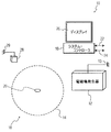
図1は、本開示のある実施形態に基づく金属アーチファクト補償を特徴とする電磁的追跡システム10のブロック図である。電磁場発生器12が、概括的に参照符号16によって示される関心領域中に電磁場14を発生させる。電磁場発生器12は、参照符号13によって示されるように、固定位置を基準とされている(referenced)。電磁場14は、電磁場および関心領域の直近の金属アーチファクト(図示せず)の存在に応答したゆがみを受ける。システム・コントローラ18は、追跡されるべきセンサー20の位置(センサーは関心領域16内に位置されている)を、金属ゆがみ補償された電磁場の関数として決定するよう構成されている。これについては本稿でさらに論じる。
FIG. 1 is a block diagram of an
システム・コントローラ18はいかなる好適なコンピュータおよび/またはセンサー・インターフェースを有していることもでき、該コントローラはさらに、電磁場追跡のための金属ゆがみ補償を実行することに関する、ここで論じられるさまざまな機能を実行するための好適な命令をプログラムされている。システム・コントローラ18は、電磁的追跡システム10の他の要素に電子的に結合するための、たとえば22および24のようなさまざまな入出力信号線を含んでいてもよい。好適な表示装置26が、たとえば所与の電磁的追跡用途の際のシステム・オペレータによる使用のために、システム・コントローラ18に結合されている。さらに、入出力装置、ポインティング・デバイスなど(図示せず)のような追加的な装置が電磁的追跡用途の所与の実装のために必要に応じて設けられていてもよい。
The
電磁的追跡システム10はさらに、第二の追跡機構28を含む。第二の追跡機構28は、参照符号29で示されるように、ある固定位置を基準とされている。ある実施形態では、システム・コントローラ18の入出力22および24は電磁場発生器12および第二の追跡機構28にそれぞれ結合されることができる。第二の機構28は、第二の機構28と電磁場発生器12との間の空間関係を判別するよう構成されている。ある実施形態では、第二の機構28は、本稿で論じるような所与の電磁的追跡用途のために所望される距離および位置情報を与えるのに好適な光学式追跡システムを有する。
The
ある実施形態では、参照センサーのアレイは、一つまたは複数のモジュラー・アレイを有する。各モジュラー・アレイは(i)所定の構成または形ならびに(ii)一つまたは複数の参照センサーを有する。たとえば、モジュラー・アレイは、半円筒形をもつアレイを有することができる。該半円筒形のアレイは、患者の腹部または胸郭の一方または両方のあたりで実施される介入(インターベンション)での使用のために構成される。もう一つの例では、モジュラー・アレイは実質的にフラット・パネルのアレイを有することができる。該フラット・パネル・アレイは一つまたは複数の参照センサーを所定の構成で含み、さらに患者の下への配置のために構成されている。さらにもう一つの例では、モジュラー・アレイはかご形を有するアレイを有することができる。該かごアレイは、患者の抹消肢(peripheral limb)における介入のために構成される。 In certain embodiments, the array of reference sensors has one or more modular arrays. Each modular array has (i) a predetermined configuration or shape and (ii) one or more reference sensors. For example, a modular array can have an array with a semi-cylindrical shape. The semi-cylindrical array is configured for use in interventions performed around one or both of the patient's abdomen or thorax. In another example, the modular array can have a substantially flat panel array. The flat panel array includes one or more reference sensors in a predetermined configuration and is further configured for placement under the patient. In yet another example, the modular array can have an array having a cage shape. The car array is configured for intervention in the patient's peripheral limb.
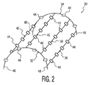
図2は、本開示のある実施形態に基づくある構成における参照センサーのアレイ30を示す概略図である。参照センサーのアレイ30は、所望される形の非金属物質内に埋め込まれることができる。非金属物質はたとえば、所望される形を維持するために適切な特性をもついかなる好適なプラスチックであることもできる。所望される形はたとえば、図2に示される半円筒形を含むことができる。図2の実施形態では、参照センサー30のアレイは一つまたは複数のモジュラー・アレイ32、34、36、38、40、42などを有することができる。各モジュラー・アレイは(i)所定の構成または形ならびに(ii)一つまたは複数の参照センサー44を有する。
FIG. 2 is a schematic diagram illustrating an
このように、参照センサーのアレイ30は、所与の全体的な構成におけるある所与の全体的な数の参照センサーによって特徴付けることができる。したがって、全体的な構成内でのセンサーのうちの少なくとも二つの位置付けを知ることによって、残りのセンサーについての位置および配置情報を、参照センサーのアレイの所定の構成の関数として、決定できる。
In this manner, the
図3は、本開示のもう一つの実施形態に基づくもう一つの構成における参照センサーのアレイ50を示す概略図である。参照センサーのアレイは、所望される形の非金属物質内に埋め込まれることができる。非金属物質はたとえば、所望される形を維持するために適切な特性をもついかなる好適なプラスチックであることもできる。所望される形はたとえば、図3に示される実質的にフラット・パネルの形を含むことができる。図3の実施形態では、参照センサーのアレイ50は一つまたは複数のモジュラー・アレイ52、54などを有することができる。各モジュラー・アレイは(i)所定の構成または形ならびに(ii)一つまたは複数の参照センサー56を有する。
FIG. 3 is a schematic diagram illustrating an
したがって、このように、参照センサーのアレイ50は、所与の全体的な構成におけるある所与の全体的な数の参照センサーによって特徴付けることができる。したがって、全体的な構成内でのセンサーのうちの少なくとも二つまたはそれ以上の位置付けを知ることによって、残りのセンサーについての位置および配置情報を、参照センサーのアレイの所定の構成情報の関数として、決定できる。
Thus, in this way, the
モジュラー・アレイはさらに、あらかじめ製作されたセンサー・アレイの一つまたは複数のモジュラー部分(modular portion)を有する(comprise)こともできる。そのような実施形態では、モジュラー部分はさらに、図2および図3のそれぞれ参照符号48および49によって概括的に示される、少なくとも二つの位置合わせ機構を含むことができる。位置合わせ機構は、諸モジュラー部分を合わせた所定の配置を確立する際に使うためのものである。さらに、前記少なくとも二つの位置合わせ機構は、インターロック機構を有する。前記インターロック機構は、二つ以上のモジュラー・アレイを所定の配置で一緒にロックする際に使うためのものである。該二つ以上のモジュラー・アレイを一緒にロックする結果として、インターロック機構は、電磁場発生器の位置付けに対する参照センサーのアレイの位置の位置合わせを実行する能力を保証する。
The modular array may further comprise one or more modular portions of a prefabricated sensor array. In such embodiments, the modular portion may further include at least two alignment features, generally indicated by
ある実施形態では、フラット・パネルは、平均的な患者の胸郭および腹部にわたる長さ方向の大きさと、CTまたはX線テーブルの幅と釣り合う幅方向の大きさをもつプラスチック片を有することができる。フラット・パネルの厚さは、約1センチメートル(1cm)のオーダーであることができる。フラット・パネルは、当該電磁的追跡システムと一緒に使うためのセンサーを収容するために好適な、前記プラスチック中にドリルで穿たれたソケットを用意される。ある実施形態では、ソケットは、1インチのオーダーの縦横の公称間隔をもつグリッド編成に配置される。同様にして、参照センサーの半円筒アレイ30は埋め込まれた参照センサーをもって製作されることができる。半円筒アレイ30はさらにモールドされたペグを設けられることができ、フラット・パネル50は前記プラスチック中の孔を設けられることができ、それにより、それらの二つのプラスチック片は、たとえば患者のまわりで、互いに対して一時的に固定されることができる。
In some embodiments, the flat panel can have a piece of plastic with a length dimension that spans the average patient's rib cage and abdomen and a width dimension that matches the width of the CT or X-ray table. The thickness of the flat panel can be on the order of about 1 centimeter (1 cm). The flat panel is provided with a socket drilled into the plastic suitable for receiving a sensor for use with the electromagnetic tracking system. In one embodiment, the sockets are arranged in a grid formation with nominal horizontal and vertical spacings on the order of 1 inch. Similarly, a
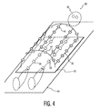
図4は、本開示のある実施形態に基づく、概括的に参照符号60によって示される、一緒に結合された異なる構成の参照センサーの複合アレイを示す概略図である。このように、図4に示される参照センサーのアレイは、第一および第二の参照センサー・アレイ30および50をそれぞれ有する。第一の参照センサー・アレイ30は、一つまたは複数の参照センサー44の第一の構成を含んでおり、第二の参照センサー・アレイ50は、一つまたは複数の参照センサー56の第二の構成を含んでいる。さらに、第一の参照センサー・アレイ30の構成は、第二の参照センサー・アレイ50の構成とは異なっていることができる。
FIG. 4 is a schematic diagram illustrating a composite array of different configurations of reference sensors coupled together, indicated generally by reference numeral 60, in accordance with an embodiment of the present disclosure. Thus, the array of reference sensors shown in FIG. 4 has first and second
図4に示されるように、本開示のある実施形態は、肝生検のために適用可能である。フラット・パネル・アレイ50は、参照符号62によって点線で概括的に示される患者の、背中の下に設置するよう構成されている。半円筒アレイを有する他方のアレイ30は、患者の腹部のまわりへの設置のために構成されている。さらに、フラット・パネル・アレイ50は、金属コンポーネントを含むテーブル64上での使用のために意図されている。ここで、テーブル64はX線テーブルまたはCTテーブルの一つまたは両方を有することができる。
As shown in FIG. 4, certain embodiments of the present disclosure are applicable for liver biopsy. The
図5は、本開示のある実施形態に基づく一緒に結合された異なる構成の参照センサーの複合アレイ(30、50)を含む電磁的追跡システム10のブロック図である。所定の既知の構成をもつ参照センサーの少なくとも一つのアレイ(30、50)が関心領域の直近に配置されている。この実施形態では、システム・コントローラ18は、電磁場14を介した参照センサー(44、56)のうちの一つまたは複数の励起に応答して、電磁場発生器12に対する参照センサーのアレイ(30、50)の位置の第一のセットを決定するよう構成されている。電磁場発生器12以外の第二の機構28が、第二の機構28に対する参照センサーのアレイ(30、50)のうちの少なくとも一つまたは複数のセンサーの位置の第二のセットの第一の部分を決定する。前記一つまたは複数のセンサーは、参照センサーのモジュラー・アレイの三次元的な(3D)配向および位置の記述を与えるよう構成されている。さらに、第二の機構28は、電磁場発生器12と既知の空間的関係にある。システム・コントローラ18は、(i)前記第二の機構(28)を使って決定された位置の前記第二のセットの前記第一の部分および(ii)参照センサーのアレイ(30、50)の所定の既知の構成に応答して、参照センサーのアレイ(30、50)のうちの参照センサー(44、56)の位置の前記第二のセットの残りの部分を決定する。さらに、システム・コントローラ18は、参照センサーのアレイの参照センサー位置の前記第一のセットおよび前記第二のセットの関数として、関心領域における電磁場の金属ゆがみについての補償を実行するよう構成される。
FIG. 5 is a block diagram of an
CTガイド式肝生検については、フラットな長方形アレイ50がCTテーブル64の上に設置される。患者62はその長方形アレイ50の上に位置されることになる。次いで半円筒アレイ30が患者の上に配置され、フラット・パネル・アレイ50にしっかりとロックされることになる。次に、参照アレイ(30、50)の位置は、場発生器12の位置に位置合わせされる。ある実施形態では、位置特定は、参照センサー・アレイ(30、50)および場発生器12の両方を見ることのできる光学式追跡器28を用いて実行される。当該手順の間、システム・コントローラは参照センサー(30、50)からの位置測定値を取得する。センサーの真の位置は:(1)製造工程の間に決定される、各アレイ内でのセンサーの相対位置の知識および(2)この実施形態では前記光学式追跡器を使って決定される、各アレイの場発生器に対する相対位置の知識を使って計算されることになる。これらの測定値が次いで、たとえば米国特許第6,400,139号および第6,377,041号で開示されているアルゴリズムを使って電磁場のゆがみを定量化し、補正するために使われることになる。
For CT guided liver biopsy, a flat
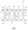
図6は、本開示のもう一つの実施形態に基づく互いに物理的に離間した異なる構成(50、102、104)の参照センサーの複合アレイを示す、電磁的追跡システム実装100の概略図である。この実施形態では、参照センサーのアレイ(50、102、104)はそれぞれ、参照センサー(56、106、108)の複合アレイを有する。たとえば、参照センサーの第一のアレイは、概括的に参照符号50によって示される。参照センサーの第二のアレイは、概括的に参照符号102によって示される。参照センサーの第二のアレイ102は、参照符号103によって示されるようにある固定位置を基準とされている。参照センサーの第三のアレイは、参照符号104によって概括的に示される。参照センサーの第三のアレイ104は、参照符号105によって示されるようにある固定位置を基準とされている。この実施形態では、参照センサーの第二のアレイ102は、参照センサーの第一のアレイ50とは物理的に離れて位置されることができる。参照センサーの第二のアレイ102はまた、参照センサーの第三のアレイ104とは物理的に離れて維持されることができる、などである。図7は、本開示のもう一つの実施形態に基づくさらにもう一つの構成における参照センサーのアレイ110を示す概略図である。参照センサーのアレイ110は、所望される形の非金属物質内に埋め込まれる。非金属物質は、たとえば、所望される形を維持するのに適切な特性をもついかなる好適なプラスチックであることもできる。所望される形はたとえばかご形を含むことができる。図7に示される形は、図8の所望されるかご形に形成される前の参照センサーのアレイのほぼ平面状の形を示している。図7の実施形態では、参照センサーのアレイ110は、一つまたは複数のモジュラー・アレイ112、114、116、118、120、122、124などを有することができる。各モジュラー・アレイは(i)所定の構成または形ならびに(ii)一つまたは複数の参照センサー126を有する。
FIG. 6 is a schematic diagram of an electromagnetic
図7のモジュラー・アレイは、参照符号(128−1、128−2)および(129−1、129−2)によって概括的に示される、少なくとも二つの位置合わせ機構をさらに含むことができる。位置合わせ機構は、諸モジュラー部分を合わせた所定の配置を確立する際に使うためのものである。さらに、前記少なくとも二つの位置合わせ機構は、任意の好適なインターロック機構を有することができる。たとえば、前記インターロック機構は、相補的なインターロック・タブを含んでいてもよい。ここで、タブ128−1はタブ129−1とロックするよう構成され、タブ128−2はタブ129−2とロックするよう構成される。インターロック機構は、諸アレイを所定の配置で一緒にロックする際に使うためのものである。所定の配置とはこの実施形態では、かご形を含む。該二つ以上のモジュラー・アレイを一緒にロックする結果として、インターロック機構は、電磁場発生器12の位置付けに対する参照センサーのアレイ110の位置の位置合わせを実行する能力を保証する。
The modular array of FIG. 7 can further include at least two alignment features, generally indicated by reference numerals (128-1, 128-2) and (129-1, 129-2). The alignment mechanism is for use in establishing a predetermined arrangement that combines the modular portions. Furthermore, the at least two alignment mechanisms can have any suitable interlock mechanism. For example, the interlock mechanism may include complementary interlock tabs. Here, tab 128-1 is configured to lock with tab 129-1 and tab 128-2 is configured to lock with tab 129-2. The interlock mechanism is for use when the arrays are locked together in a predetermined arrangement. In this embodiment, the predetermined arrangement includes a cage shape. As a result of locking the two or more modular arrays together, the interlock mechanism ensures the ability to perform alignment of the position of the array of
図8は、本開示のある実施形態に基づく用途における使用のための、図7の参照センサーのアレイを示す概略図である。換言すれば、モジュラー・アレイ110は、かご形をもつアレイを有する。該かごアレイは、患者の抹消肢(peripheral limb)140における介入のために構成される。このように、参照センサーのアレイ110は、所与の全体的な構成におけるある所与の全体的な数の参照センサーによって特徴付けることができる。したがって、全体的な構成内でのセンサーのうちの少なくとも一つまたは複数の位置付けを知ることによって、残りのセンサーについての位置および配置情報を、参照センサーのアレイの所定の構成情報の関数として、決定できる。すなわち、前記一つまたは複数のセンサーは、参照センサーのモジュラー・アレイの三次元的な(3D)配向および位置の記述を与えるよう構成されている。
FIG. 8 is a schematic diagram illustrating the array of reference sensors of FIG. 7 for use in applications according to certain embodiments of the present disclosure. In other words, the
本開示のもう一つの実施形態によれば、金属アーチファクトの補償を特徴とする電磁的追跡方法が開示される。本方法は、関心領域中に電磁場を発生させる電磁場発生器を提供することを含む。電磁場は、電磁場および関心領域の直近の金属アーチファクトの存在に応答したゆがみを受けることを注意しておく。本方法はさらに、関心領域の直近に配された、所定の既知の構成を有する参照センサーのアレイを提供することを含む。電磁場発生器に対する参照センサーのアレイの位置の第一のセットが、電磁場を介して参照センサーのうちの一つまたは複数の励起に応答して、決定される。電磁場以外の第二の機構を使って、該第二の機構に対する参照センサーのアレイのうちの少なくとも一つまたは複数の参照センサーの位置の第二のセットの第一の部分が決定される。前記第二の機構は、電磁場発生器と既知の空間的関係にある。 According to another embodiment of the present disclosure, an electromagnetic tracking method featuring metal artifact compensation is disclosed. The method includes providing an electromagnetic field generator that generates an electromagnetic field in a region of interest. Note that the electromagnetic field is distorted in response to the presence of the electromagnetic field and the presence of metal artifacts in the immediate area of interest. The method further includes providing an array of reference sensors having a predetermined known configuration disposed proximate to the region of interest. A first set of positions of the array of reference sensors relative to the electromagnetic field generator is determined in response to excitation of one or more of the reference sensors via the electromagnetic field. A second mechanism other than the electromagnetic field is used to determine a first portion of a second set of positions of at least one or more reference sensors in the array of reference sensors for the second mechanism. The second mechanism has a known spatial relationship with the electromagnetic field generator.
次いで、(i)前記第二の機構を使って決定された位置の前記第二のセットの前記第一の部分および(ii)参照センサーのアレイの所定の既知の構成に応答して、参照センサーのアレイのうちの参照センサーの位置の前記第二のセットの残りの部分が決定される。その後、本方法は、参照センサーのアレイの参照センサー位置の前記第一のセットおよび前記第二のセットの関数として、関心領域における電磁場の金属ゆがみについての補償することを含む。本方法はさらに、関心領域内の追跡されるべきセンサーの位置を、金属ゆがみ補償された電磁場の関数として決定することを含むことができる。 A reference sensor in response to (i) a predetermined known configuration of the first portion of the second set of positions determined using the second mechanism and (ii) an array of reference sensors; The remaining portions of the second set of reference sensor positions in the array are determined. Thereafter, the method includes compensating for metal distortion of the electromagnetic field in the region of interest as a function of the first set and the second set of reference sensor positions of the array of reference sensors. The method can further include determining a position of the sensor to be tracked within the region of interest as a function of the electromagnetic distortion compensated electromagnetic field.
ある実施形態では、前記第二の機構はさらに、前記第二の機構と前記電磁場発生器との間の空間的関係を判別するよう構成される。前記第二の機構はたとえば、光学式追跡システムを有することができる。もう一つの実施形態では、前記第二の機構は、特定の電磁的追跡システム適用の要請に応じて、たとえば好適な直接的物理的測定、好適な音波位置特定または好適な電波位置特定の一つまたは複数を有することができる。 In some embodiments, the second mechanism is further configured to determine a spatial relationship between the second mechanism and the electromagnetic field generator. The second mechanism can have, for example, an optical tracking system. In another embodiment, the second mechanism may be one of suitable direct physical measurements, suitable sonic location or suitable radio location, for example, upon request for a particular electromagnetic tracking system application. Or it can have more than one.
参照センサーのアレイは、一つまたは複数のモジュラー・アレイを有することができる。各モジュラー・アレイは(i)所定の構成または形ならびに(ii)一つまたは複数の参照センサーを有する。ある実施形態では、モジュラー・アレイは、半円筒形をもつアレイを有する。該半円筒形のアレイは、患者の腹部または胸郭の一方または両方のあたりで実施される介入での使用のために構成される。もう一つの実施形態では、モジュラー・アレイは実質的にフラット・パネル・アレイを有する。該フラット・パネル・アレイは一つまたは複数の参照センサーを所定の構成で含み、さらに患者の下への設置のために構成されている。該フラット・パネル・アレイは、金属コンポーネントを含むテーブル上での使用のために意図されている。ここで、該テーブルはX線テーブルまたはCTテーブルの一つまたは両方を有することができる。さらにもう一つの実施形態では、モジュラー・アレイはかご形を有するアレイを有することができる。該かごアレイは、患者の頭部および/または抹消肢における介入のために構成される。 The array of reference sensors can have one or more modular arrays. Each modular array has (i) a predetermined configuration or shape and (ii) one or more reference sensors. In some embodiments, the modular array has an array with a semi-cylindrical shape. The semi-cylindrical array is configured for use with interventions performed around one or both of the patient's abdomen or thorax. In another embodiment, the modular array has a substantially flat panel array. The flat panel array includes one or more reference sensors in a predetermined configuration and is further configured for placement under a patient. The flat panel array is intended for use on a table containing metal components. Here, the table can comprise one or both of an X-ray table or a CT table. In yet another embodiment, the modular array can have an array having a cage shape. The cage array is configured for intervention in the patient's head and / or peripheral limb.
モジュラー・アレイはさらに、あらかじめ製作されたセンサー・アレイの、少なくとも二つの位置合わせ機構をもつモジュラー部分を有してもよい。位置合わせ機構は、諸モジュラー部分を合わせた所定の配置を確立する際に使うためのいかなる好適な機構(単数または複数)を有することもできる。前記少なくとも二つの位置合わせ機構はたとえば、任意の好適なインターロック機構を有することができる。前記インターロック機構は、二つ以上のモジュラー・アレイを所定の配置で一緒にロックする際に使うことができる。さらに、前記位置合わせ機構は、電磁場発生器の位置付けに対する参照センサーのアレイの位置の位置合わせを実行する能力を可能にする。 The modular array may further include a modular portion of the prefabricated sensor array having at least two alignment features. The alignment mechanism may have any suitable mechanism or mechanisms for use in establishing a predetermined arrangement that combines the modular portions. The at least two alignment mechanisms can have any suitable interlock mechanism, for example. The interlock mechanism can be used to lock two or more modular arrays together in a predetermined arrangement. Furthermore, the alignment mechanism allows the ability to perform alignment of the position of the array of reference sensors with respect to the positioning of the electromagnetic field generator.
もう一つの実施形態では、参照センサーのアレイは、第一および第二の参照センサー・アレイを有することができる。第一の参照センサー・アレイは、一つまたは複数の参照センサーの第一の構成を含んでいる。第二の参照センサー・アレイは、一つまたは複数の参照センサーの第二の構成を含んでいる。ある実施形態では、前記第一の構成は、前記第二の構成とは異なっている。 In another embodiment, the array of reference sensors can have first and second reference sensor arrays. The first reference sensor array includes a first configuration of one or more reference sensors. The second reference sensor array includes a second configuration of one or more reference sensors. In one embodiment, the first configuration is different from the second configuration.
もう一つの実施形態では、参照センサーのアレイは、参照センサーの第一のアレイおよび参照センサーの第二のアレイを有しており、該参照センサーの第二のアレイは、参照センサーの第一のアレイとは物理的に離れて維持される。もう一つの実施形態では、参照センサーのアレイは、所望される形の非金属物質内に埋め込まれる。所望される形は、(i)半円筒形、(ii)実質的にフラット・パネルの形または(iii)かご形のうちの一つまたは複数を含むことができる。 In another embodiment, the array of reference sensors comprises a first array of reference sensors and a second array of reference sensors, the second array of reference sensors comprising a first array of reference sensors. It is kept physically separate from the array. In another embodiment, the array of reference sensors is embedded in the desired form of non-metallic material. Desired shapes can include one or more of (i) a semi-cylindrical shape, (ii) a substantially flat panel shape, or (iii) a cage shape.
本開示の実施形態は、参照センサーのあらかじめ製作されたアレイの使用を含む。これらのアレイは、EMTSシステムにおけるゆがみのための磁場を監視するための、簡単、高速かつ臨床的に実際的な方法を提供する。次いで、介入の際に、(たとえば米国特許第6,400,139号および第6,377,041号で開示されているようにして)補正変換が計算され、適用されることができる。 Embodiments of the present disclosure include the use of a prefabricated array of reference sensors. These arrays provide a simple, fast and clinically practical way to monitor magnetic fields for distortion in EMTS systems. Then, during the intervention, a correction transformation can be calculated and applied (eg, as disclosed in US Pat. Nos. 6,400,139 and 6,377,041).
上記では少数の例示的な実施形態のみが詳細に記述されてきたが、当業者は、本開示の実施形態の新しい教示および利点から実質的に外れることなく、例示的な実施形態に数多くの修正が可能であることをすぐ理解するであろう。たとえば、本開示の実施形態は、医療機器、インプラント、撮像装置および/または医療ベッド、テーブルまたは患者を支持する他の機構によって導入されるゆがみの補正のために使われることができる。前記の実施形態はまた、さまざまな器官(肝臓、心臓、脳、前立腺など)を目標にした、いくらでもある画像ガイドされた介入的な医療手順(生検、ラジオ波焼灼療法、凍結凝固療法、短距離放射線療法、カテーテル法、化学塞栓形成療法など)のために使われることもできる。さらに、画像ガイダンスは、超音波、MRI、CT、X線、PET、SPECTおよび/または光学的な撮像のいかなる組み合わせによって提供されることもできる。したがって、そのようなあらゆる修正は、付属の請求項において定義される本開示の具現の範囲内に含められることが意図されている。請求項において、ミーンズ・プラス・ファンクションの節は、請求項に記載される機能を実行するものとしてここに記載される諸構造をカバーすることが意図されており、構造的な等価物のみならず等価な諸構造をカバーすることが意図されている。 Although only a few exemplary embodiments have been described in detail above, those skilled in the art will recognize that numerous modifications to the exemplary embodiments without substantially departing from the new teachings and advantages of the embodiments of the present disclosure. You will immediately understand that is possible. For example, embodiments of the present disclosure can be used for correction of distortions introduced by medical devices, implants, imaging devices and / or medical beds, tables or other mechanisms that support a patient. The embodiments described above also include a number of image-guided interventional medical procedures (biopsy, radiofrequency ablation, cryocoagulation, short-term therapy) targeting various organs (liver, heart, brain, prostate, etc.). Distance radiation therapy, catheterization, chemoembolization therapy, etc.). In addition, image guidance can be provided by any combination of ultrasound, MRI, CT, X-ray, PET, SPECT and / or optical imaging. Accordingly, all such modifications are intended to be included within the scope of implementation of the present disclosure as defined in the appended claims. In the claims, the means-plus-function section is intended to cover the structures described herein as performing the functions described in the claims, as well as structural equivalents. It is intended to cover equivalent structures.
さらに、一つまたは複数の請求項に括弧内に入れられた参照符号があったとしても、それは当該請求項を限定するものと解釈してはならない。「有する」および「含む」などの語は、何らかの請求項または明細書全体において挙げられているもの以外の要素またはステップの存在を排除しない。要素の単数形の言及はそのような要素の複数の言及を排除せず、逆に複数形の言及はそのような要素の単数の言及を排除しない。上記の実施形態の一つまたは複数は、いくつかの相異なる要素を有するハードウェアによって実装されてもよいし、および/または好適にプログラムされたコンピュータによって実装されてもよい。いくつかの手段を列挙する装置請求項では、それらの手段のいくつかは同一のハードウェア項目によって具現されてもよい。ある種の施策が互いに異なる従属請求項に記載されているというだけの事実が、それらの施策の組み合わせが有利に使用できないことを示すものではない。 Moreover, any reference signs placed between parentheses in one or more claims shall not be construed as limiting the claims. The words “comprising” and “including” do not exclude the presence of elements or steps other than those listed in any claim or specification. Reference to the singular of an element does not exclude a plurality of references to such elements, and conversely, a reference to the singular does not exclude singular references to such elements. One or more of the above embodiments may be implemented by hardware having several different elements and / or may be implemented by a suitably programmed computer. In the device claim enumerating several means, several of these means may be embodied by one and the same item of hardware. The mere fact that certain measures are recited in mutually different dependent claims does not indicate that a combination of these measures cannot be used to advantage.
Claims (15)
関心領域中に電磁場を発生させる電磁場発生器を提供する段階であって、前記電磁場は、該電磁場および前記関心領域の直近の金属アーチファクトの存在に応答したゆがみを受け;
前記関心領域の直近に配された、所定の既知の構成を有する参照センサーのアレイを提供する段階と;
前記電磁場発生器に対する前記アレイの参照センサーの位置の第一のセットを、前記電磁場を介して前記参照センサーのうちの一つまたは複数の励起に応答して、決定する段階と;
前記電磁場発生器と既知の空間的関係にある、金属アーチファクトによって影響されない第二の機構を使って、該第二の機構に対する参照センサーの前記アレイの参照センサーの位置の第二のセットの第一の部分を決定する段階と;
(i)前記第二の機構を使って決定された位置の前記第二のセットの前記第一の部分および(ii)参照センサーの前記アレイの所定の既知の構成に応答して、参照センサーの前記アレイのうちの参照センサーの位置の前記第二のセットの残りの部分を決定する段階と;
参照センサーの前記アレイの参照センサー位置の前記第一のセットおよび前記第二のセットの関数として、前記関心領域における電磁場の金属ゆがみについて補償する段階とを有する、
方法。 An electromagnetic tracking method characterized by metal artifact compensation comprising:
Providing an electromagnetic field generator for generating an electromagnetic field in a region of interest, wherein the electromagnetic field is distorted in response to the presence of the electromagnetic field and a metal artifact in the immediate vicinity of the region of interest;
Providing an array of reference sensors having a predetermined known configuration disposed proximate to the region of interest;
Determining a first set of reference sensor positions of the array relative to the electromagnetic field generator in response to excitation of one or more of the reference sensors via the electromagnetic field;
Using a second mechanism that is in a known spatial relationship with the electromagnetic field generator and not affected by metal artifacts, a first of a second set of reference sensor positions of the array of reference sensors relative to the second mechanism. Determining the part of;
In response to a predetermined known configuration of the first portion of the second set of positions determined using the second mechanism and (ii) the array of reference sensors. Determining the remaining portion of the second set of reference sensor locations in the array;
Compensating for metallic distortion of the electromagnetic field in the region of interest as a function of the first set and the second set of reference sensor positions of the array of reference sensors;
Method.
関心領域中に電磁場を発生させる電磁場発生器であって、前記電磁場は、該電磁場および前記関心領域の直近の金属アーチファクトの存在に応答したゆがみを受けるような電磁場発生器と;
前記関心領域の直近に配された、所定の既知の構成を有する参照センサーの少なくとも一つのアレイと;
前記電磁場発生器に対する前記アレイの参照センサーの位置の第一のセットを、前記電磁場を介して前記参照センサーのうちの一つまたは複数の励起に応答して、決定する、システム・コントローラと;
前記電磁場発生器と既知の空間的関係にある、金属アーチファクトによって影響されない第二の機構であって、該第二の機構に対する参照センサーの前記アレイの参照センサーの位置の第二のセットの第一の部分を決定する、第二の機構とを有しており、
前記システム・コントローラがさらに、(i)前記第二の機構を使って決定された位置の前記第二のセットの前記第一の部分および(ii)参照センサーの前記アレイの所定の既知の構成に応答して、参照センサーの前記アレイのうちの参照センサーの位置の前記第二のセットの残りの部分を決定するよう構成されており、参照センサーの前記アレイの参照センサー位置の前記第一のセットおよび前記第二のセットの関数として、前記関心領域における電磁場の金属ゆがみについて補償するよう構成されている、
電磁的追跡システム。 An electromagnetic tracking system featuring metal artifact compensation:
An electromagnetic field generator for generating an electromagnetic field in a region of interest, the electromagnetic field being subject to distortion in response to the presence of the electromagnetic field and the presence of a metal artifact in the immediate vicinity of the region of interest;
At least one array of reference sensors having a predetermined known configuration disposed proximate to the region of interest;
A system controller for determining a first set of reference sensor positions of the array relative to the electromagnetic field generator in response to excitation of one or more of the reference sensors via the electromagnetic field;
A second mechanism in a known spatial relationship with the electromagnetic field generator and unaffected by metal artifacts, the first of the second set of reference sensor positions of the array of reference sensors relative to the second mechanism. A second mechanism for determining a portion of
The system controller further includes (i) a predetermined known configuration of the first portion of the second set of positions determined using the second mechanism and (ii) the array of reference sensors. In response, the first set of reference sensor positions in the array of reference sensors configured to determine a remaining portion of the second set of reference sensor positions in the array of reference sensors. And configured to compensate for metal distortion of the electromagnetic field in the region of interest as a function of the second set;
Electromagnetic tracking system.
参照センサーの前記第一のアレイとは物理的に離れて維持される参照センサーの第二のアレイをさらに有する、
請求項2記載のシステム。 The array of reference sensors includes a first array of reference sensors, the system further comprising:
Further comprising a second array of reference sensors maintained physically separate from said first array of reference sensors;
The system according to claim 2.
Applications Claiming Priority (3)
| Application Number | Priority Date | Filing Date | Title |
|---|---|---|---|
| US75075605P | 2005-12-15 | 2005-12-15 | |
| US60/750,756 | 2005-12-15 | ||
| PCT/IB2006/054748 WO2007069186A2 (en) | 2005-12-15 | 2006-12-11 | Electromagnetic tracking method and apparatus for compensation of metal artifacts using modular arrays of reference sensors |
Publications (2)
| Publication Number | Publication Date |
|---|---|
| JP2009519086A JP2009519086A (en) | 2009-05-14 |
| JP5451076B2 true JP5451076B2 (en) | 2014-03-26 |
Family
ID=38069120
Family Applications (1)
| Application Number | Title | Priority Date | Filing Date |
|---|---|---|---|
| JP2008545213A Expired - Fee Related JP5451076B2 (en) | 2005-12-15 | 2006-12-11 | Electromagnetic tracking method and apparatus for metal artifact compensation using a modular array of reference sensors. |
Country Status (6)
| Country | Link |
|---|---|
| US (1) | US7902816B2 (en) |
| EP (1) | EP1962682B1 (en) |
| JP (1) | JP5451076B2 (en) |
| CN (1) | CN101325908B (en) |
| AT (1) | ATE545365T1 (en) |
| WO (1) | WO2007069186A2 (en) |
Families Citing this family (16)
| Publication number | Priority date | Publication date | Assignee | Title |
|---|---|---|---|---|
| FR2904427B1 (en) * | 2006-07-25 | 2010-08-20 | Univ Poitiers | SYSTEM AND METHOD FOR THREE-DIMENSIONAL LOCATION OF AN OBJECT IN A VOLUME |
| US20100099981A1 (en) * | 2008-10-21 | 2010-04-22 | Fishel Robert S | Trans-Septal Catheterization Device And Method |
| EP2384158A1 (en) * | 2009-01-05 | 2011-11-09 | Koninklijke Philips Electronics N.V. | System and method for dynamic metal distortion compensation for electromagnetic tracking systems |
| EP2588194B1 (en) * | 2010-06-30 | 2018-01-10 | Koninklijke Philips N.V. | System for guided adaptive brachytherapy |
| US20140064442A1 (en) * | 2012-08-31 | 2014-03-06 | Ghansham Das AGARWAL | Novel device for marking location of organs on skin as per cat scan |
| US9055915B2 (en) * | 2012-07-10 | 2015-06-16 | Ghansham D. Agarwal | Device for externally marking the location of organs on skin during a cat scan |
| US10264995B2 (en) * | 2013-12-04 | 2019-04-23 | Obalon Therapeutics, Inc. | Systems and methods for locating and/or characterizing intragastric devices |
| US9474466B2 (en) * | 2013-12-23 | 2016-10-25 | Biosense Webster (Israel) Ltd. | Low-profile location pad for magnetic-based intra-body probe tracking system |
| US10285760B2 (en) | 2015-02-04 | 2019-05-14 | Queen's University At Kingston | Methods and apparatus for improved electromagnetic tracking and localization |
| US10772531B2 (en) | 2016-01-26 | 2020-09-15 | St. Jude Medical International Holding S.á r.l. | Magnetic field distortion detection and correction in a magnetic localization system |
| JP6640382B2 (en) * | 2016-05-03 | 2020-02-05 | セント・ジュード・メディカル・インターナショナル・ホールディング・エスエーアールエルSt. Jude Medical International Holding S.a,r.l. | Magnetic field distortion detection and correction in magnetic localization systems |
| CN105919595B (en) * | 2016-05-17 | 2019-05-21 | 浙江大学宁波理工学院 | System and method for the micro device in pursuit movement object body with magnetic signal |
| US20190167148A1 (en) * | 2017-12-04 | 2019-06-06 | Bard Access Systems, Inc. | Systems And Methods For Visualizing Anatomy, Locating Medical Devices, Or Placing Medical Devices |
| FR3089780B1 (en) * | 2018-12-12 | 2022-07-22 | Quantum Surgical | Automatic registration of a robot arm for a medical intervention |
| JP2020146286A (en) * | 2019-03-14 | 2020-09-17 | 株式会社リコー | Information processing device, information processing method, program and biological signal measurement system |
| US11719850B2 (en) * | 2019-06-20 | 2023-08-08 | Sony Interactive Entertainment Inc. | Detecting and compensating for magnetic interference in electromagnetic (EM) positional tracking |
Family Cites Families (13)
| Publication number | Priority date | Publication date | Assignee | Title |
|---|---|---|---|---|
| US5729129A (en) * | 1995-06-07 | 1998-03-17 | Biosense, Inc. | Magnetic location system with feedback adjustment of magnetic field generator |
| US5831260A (en) * | 1996-09-10 | 1998-11-03 | Ascension Technology Corporation | Hybrid motion tracker |
| GB2331807B (en) * | 1997-11-15 | 2002-05-29 | Roke Manor Research | Catheter tracking system |
| ES2253882T3 (en) * | 1998-03-30 | 2006-06-01 | Biosense Webster, Inc. | THREE AXLE COIL SENSOR. |
| US6377041B1 (en) | 1998-12-17 | 2002-04-23 | Polhemus Inc. | Method and apparatus for determining electromagnetic field characteristics within a volume |
| US6233476B1 (en) * | 1999-05-18 | 2001-05-15 | Mediguide Ltd. | Medical positioning system |
| US6288785B1 (en) * | 1999-10-28 | 2001-09-11 | Northern Digital, Inc. | System for determining spatial position and/or orientation of one or more objects |
| US6400139B1 (en) * | 1999-11-01 | 2002-06-04 | Polhemus Inc. | Methods and apparatus for electromagnetic position and orientation tracking with distortion compensation |
| US20050107687A1 (en) * | 2003-11-14 | 2005-05-19 | Anderson Peter T. | System and method for distortion reduction in an electromagnetic tracker |
| JP4639199B2 (en) * | 2004-02-18 | 2011-02-23 | コーニンクレッカ フィリップス エレクトロニクス エヌ ヴィ | Measured value correction of magnetic positioning device |
| US7782046B2 (en) * | 2007-02-05 | 2010-08-24 | General Electric Company | Electromagnetic tracking method and system |
| US7902817B2 (en) * | 2007-03-26 | 2011-03-08 | General Electric Company | Electromagnetic tracking method and system |
| US20090001969A1 (en) * | 2007-06-29 | 2009-01-01 | General Electric Company | System and method for electromagnetic navigation of a magnetic field generating probe |
-
2006
- 2006-12-11 US US12/095,742 patent/US7902816B2/en active Active
- 2006-12-11 WO PCT/IB2006/054748 patent/WO2007069186A2/en active Application Filing
- 2006-12-11 CN CN2006800466734A patent/CN101325908B/en active Active
- 2006-12-11 AT AT06842437T patent/ATE545365T1/en active
- 2006-12-11 EP EP06842437A patent/EP1962682B1/en active Active
- 2006-12-11 JP JP2008545213A patent/JP5451076B2/en not_active Expired - Fee Related
Also Published As
| Publication number | Publication date |
|---|---|
| US7902816B2 (en) | 2011-03-08 |
| US20080309326A1 (en) | 2008-12-18 |
| WO2007069186A2 (en) | 2007-06-21 |
| EP1962682B1 (en) | 2012-02-15 |
| CN101325908A (en) | 2008-12-17 |
| JP2009519086A (en) | 2009-05-14 |
| EP1962682A2 (en) | 2008-09-03 |
| CN101325908B (en) | 2010-05-19 |
| WO2007069186A3 (en) | 2007-10-11 |
| ATE545365T1 (en) | 2012-03-15 |
Similar Documents
| Publication | Publication Date | Title |
|---|---|---|
| JP5451076B2 (en) | Electromagnetic tracking method and apparatus for metal artifact compensation using a modular array of reference sensors. | |
| JP5820405B2 (en) | Local error compensation system in electromagnetic tracking system | |
| EP1126787B1 (en) | Determining the location and orientation of an indwelling medical device | |
| DE69809411T2 (en) | SYSTEM AND METHOD FOR DETERMINING THE LOCALIZATION AND ORIENTATION OF A PERMANENTLY Lingering MEDICAL DEVICE | |
| US8694075B2 (en) | Intra-operative registration for navigated surgical procedures | |
| RU2519300C2 (en) | Electromagnetic tracking method and system in medical procedure | |
| US6546279B1 (en) | Computer controlled guidance of a biopsy needle | |
| US6129668A (en) | System and method to determine the location and orientation of an indwelling medical device | |
| JP6722104B2 (en) | Superimposition of intraoperative images with reference markers | |
| WO2010076676A1 (en) | System and method for dynamic metal distortion compensation for electromagnetic tracking systems | |
| Cleary et al. | Electromagnetic tracking for image-guided abdominal procedures: Overall system and technical issues | |
| Najmaei et al. | Image‐guided techniques in renal and hepatic interventions | |
| JP2017012760A (en) | Flat location pad using non-concentric coils | |
| Bao et al. | Ultrasound-to-computer-tomography registration for image-guided laparoscopic liver surgery | |
| Wagner et al. | Electromagnetic organ tracking allows for real-time compensation of tissue shift in image-guided laparoscopic rectal surgery: results of a phantom study | |
| US20110270083A1 (en) | System and method for dynamic metal distortion compensation for electromagnetic tracking systems | |
| Krücker et al. | An electro-magnetically tracked laparoscopic ultrasound for multi-modality minimally invasive surgery | |
| Nicolau et al. | Clinical evaluation of a respiratory gated guidance system for liver punctures | |
| JP2007501647A (en) | Use of magnetic resonance imaging to locate anatomical targets | |
| Linte et al. | Calibration and evaluation of a magnetically tracked ICE probe for guidance of left atrial ablation therapy | |
| Maier-Hein et al. | Computer-assisted needle insertion for abdominal interventions |
Legal Events
| Date | Code | Title | Description |
|---|---|---|---|
| A621 | Written request for application examination |
Free format text: JAPANESE INTERMEDIATE CODE: A621 Effective date: 20091208 |
|
| A977 | Report on retrieval |
Free format text: JAPANESE INTERMEDIATE CODE: A971007 Effective date: 20120326 |
|
| A131 | Notification of reasons for refusal |
Free format text: JAPANESE INTERMEDIATE CODE: A131 Effective date: 20120424 |
|
| A521 | Request for written amendment filed |
Free format text: JAPANESE INTERMEDIATE CODE: A523 Effective date: 20120720 |
|
| A131 | Notification of reasons for refusal |
Free format text: JAPANESE INTERMEDIATE CODE: A131 Effective date: 20130409 |
|
| A521 | Request for written amendment filed |
Free format text: JAPANESE INTERMEDIATE CODE: A523 Effective date: 20130514 |
|
| TRDD | Decision of grant or rejection written | ||
| A01 | Written decision to grant a patent or to grant a registration (utility model) |
Free format text: JAPANESE INTERMEDIATE CODE: A01 Effective date: 20131203 |
|
| A61 | First payment of annual fees (during grant procedure) |
Free format text: JAPANESE INTERMEDIATE CODE: A61 Effective date: 20131226 |
|
| R150 | Certificate of patent or registration of utility model |
Ref document number: 5451076 Country of ref document: JP Free format text: JAPANESE INTERMEDIATE CODE: R150 Free format text: JAPANESE INTERMEDIATE CODE: R150 |
|
| R250 | Receipt of annual fees |
Free format text: JAPANESE INTERMEDIATE CODE: R250 |
|
| R250 | Receipt of annual fees |
Free format text: JAPANESE INTERMEDIATE CODE: R250 |
|
| R250 | Receipt of annual fees |
Free format text: JAPANESE INTERMEDIATE CODE: R250 |
|
| R250 | Receipt of annual fees |
Free format text: JAPANESE INTERMEDIATE CODE: R250 |
|
| R250 | Receipt of annual fees |
Free format text: JAPANESE INTERMEDIATE CODE: R250 |
|
| R250 | Receipt of annual fees |
Free format text: JAPANESE INTERMEDIATE CODE: R250 |
|
| R250 | Receipt of annual fees |
Free format text: JAPANESE INTERMEDIATE CODE: R250 |
|
| LAPS | Cancellation because of no payment of annual fees |