JP2017012760A - Flat location pad using non-concentric coils - Google Patents
Flat location pad using non-concentric coils Download PDFInfo
- Publication number
- JP2017012760A JP2017012760A JP2016133070A JP2016133070A JP2017012760A JP 2017012760 A JP2017012760 A JP 2017012760A JP 2016133070 A JP2016133070 A JP 2016133070A JP 2016133070 A JP2016133070 A JP 2016133070A JP 2017012760 A JP2017012760 A JP 2017012760A
- Authority
- JP
- Japan
- Prior art keywords
- coils
- magnetic field
- field generator
- pad
- concentric
- Prior art date
- Legal status (The legal status is an assumption and is not a legal conclusion. Google has not performed a legal analysis and makes no representation as to the accuracy of the status listed.)
- Granted
Links
- 238000000034 method Methods 0.000 claims description 30
- OKTJSMMVPCPJKN-UHFFFAOYSA-N Carbon Chemical compound [C] OKTJSMMVPCPJKN-UHFFFAOYSA-N 0.000 claims description 6
- 229910052799 carbon Inorganic materials 0.000 claims description 6
- 239000000523 sample Substances 0.000 abstract description 3
- 238000002324 minimally invasive surgery Methods 0.000 abstract description 2
- 238000003384 imaging method Methods 0.000 description 13
- 230000000747 cardiac effect Effects 0.000 description 3
- 238000002594 fluoroscopy Methods 0.000 description 3
- 239000000463 material Substances 0.000 description 3
- 238000002679 ablation Methods 0.000 description 2
- 230000000694 effects Effects 0.000 description 2
- 238000004519 manufacturing process Methods 0.000 description 2
- 238000013507 mapping Methods 0.000 description 2
- RYGMFSIKBFXOCR-UHFFFAOYSA-N Copper Chemical compound [Cu] RYGMFSIKBFXOCR-UHFFFAOYSA-N 0.000 description 1
- 229910052802 copper Inorganic materials 0.000 description 1
- 239000010949 copper Substances 0.000 description 1
- 229910003460 diamond Inorganic materials 0.000 description 1
- 239000010432 diamond Substances 0.000 description 1
- 239000000835 fiber Substances 0.000 description 1
- 239000011152 fibreglass Substances 0.000 description 1
- 239000007943 implant Substances 0.000 description 1
- 238000003780 insertion Methods 0.000 description 1
- 230000037431 insertion Effects 0.000 description 1
- 230000004807 localization Effects 0.000 description 1
- 238000005259 measurement Methods 0.000 description 1
- 238000012986 modification Methods 0.000 description 1
- 230000004048 modification Effects 0.000 description 1
- 210000000056 organ Anatomy 0.000 description 1
- 230000000399 orthopedic effect Effects 0.000 description 1
- 239000004033 plastic Substances 0.000 description 1
- 239000007787 solid Substances 0.000 description 1
- 230000001225 therapeutic effect Effects 0.000 description 1
Images


Classifications
-
- A—HUMAN NECESSITIES
- A61—MEDICAL OR VETERINARY SCIENCE; HYGIENE
- A61B—DIAGNOSIS; SURGERY; IDENTIFICATION
- A61B5/00—Measuring for diagnostic purposes; Identification of persons
- A61B5/06—Devices, other than using radiation, for detecting or locating foreign bodies ; determining position of probes within or on the body of the patient
- A61B5/061—Determining position of a probe within the body employing means separate from the probe, e.g. sensing internal probe position employing impedance electrodes on the surface of the body
- A61B5/062—Determining position of a probe within the body employing means separate from the probe, e.g. sensing internal probe position employing impedance electrodes on the surface of the body using magnetic field
-
- A—HUMAN NECESSITIES
- A61—MEDICAL OR VETERINARY SCIENCE; HYGIENE
- A61B—DIAGNOSIS; SURGERY; IDENTIFICATION
- A61B1/00—Instruments for performing medical examinations of the interior of cavities or tubes of the body by visual or photographical inspection, e.g. endoscopes; Illuminating arrangements therefor
-
- A—HUMAN NECESSITIES
- A61—MEDICAL OR VETERINARY SCIENCE; HYGIENE
- A61B—DIAGNOSIS; SURGERY; IDENTIFICATION
- A61B34/00—Computer-aided surgery; Manipulators or robots specially adapted for use in surgery
- A61B34/20—Surgical navigation systems; Devices for tracking or guiding surgical instruments, e.g. for frameless stereotaxis
-
- A—HUMAN NECESSITIES
- A61—MEDICAL OR VETERINARY SCIENCE; HYGIENE
- A61B—DIAGNOSIS; SURGERY; IDENTIFICATION
- A61B5/00—Measuring for diagnostic purposes; Identification of persons
- A61B5/06—Devices, other than using radiation, for detecting or locating foreign bodies ; determining position of probes within or on the body of the patient
-
- A—HUMAN NECESSITIES
- A61—MEDICAL OR VETERINARY SCIENCE; HYGIENE
- A61B—DIAGNOSIS; SURGERY; IDENTIFICATION
- A61B6/00—Apparatus or devices for radiation diagnosis; Apparatus or devices for radiation diagnosis combined with radiation therapy equipment
-
- A—HUMAN NECESSITIES
- A61—MEDICAL OR VETERINARY SCIENCE; HYGIENE
- A61B—DIAGNOSIS; SURGERY; IDENTIFICATION
- A61B90/00—Instruments, implements or accessories specially adapted for surgery or diagnosis and not covered by any of the groups A61B1/00 - A61B50/00, e.g. for luxation treatment or for protecting wound edges
-
- H—ELECTRICITY
- H01—ELECTRIC ELEMENTS
- H01F—MAGNETS; INDUCTANCES; TRANSFORMERS; SELECTION OF MATERIALS FOR THEIR MAGNETIC PROPERTIES
- H01F27/00—Details of transformers or inductances, in general
- H01F27/28—Coils; Windings; Conductive connections
-
- H—ELECTRICITY
- H01—ELECTRIC ELEMENTS
- H01F—MAGNETS; INDUCTANCES; TRANSFORMERS; SELECTION OF MATERIALS FOR THEIR MAGNETIC PROPERTIES
- H01F27/00—Details of transformers or inductances, in general
- H01F27/28—Coils; Windings; Conductive connections
- H01F27/2823—Wires
-
- A—HUMAN NECESSITIES
- A61—MEDICAL OR VETERINARY SCIENCE; HYGIENE
- A61B—DIAGNOSIS; SURGERY; IDENTIFICATION
- A61B34/00—Computer-aided surgery; Manipulators or robots specially adapted for use in surgery
- A61B34/20—Surgical navigation systems; Devices for tracking or guiding surgical instruments, e.g. for frameless stereotaxis
- A61B2034/2046—Tracking techniques
- A61B2034/2051—Electromagnetic tracking systems
-
- A—HUMAN NECESSITIES
- A61—MEDICAL OR VETERINARY SCIENCE; HYGIENE
- A61B—DIAGNOSIS; SURGERY; IDENTIFICATION
- A61B34/00—Computer-aided surgery; Manipulators or robots specially adapted for use in surgery
- A61B34/20—Surgical navigation systems; Devices for tracking or guiding surgical instruments, e.g. for frameless stereotaxis
- A61B2034/2072—Reference field transducer attached to an instrument or patient
-
- A—HUMAN NECESSITIES
- A61—MEDICAL OR VETERINARY SCIENCE; HYGIENE
- A61B—DIAGNOSIS; SURGERY; IDENTIFICATION
- A61B34/00—Computer-aided surgery; Manipulators or robots specially adapted for use in surgery
- A61B34/70—Manipulators specially adapted for use in surgery
- A61B34/73—Manipulators for magnetic surgery
- A61B2034/731—Arrangement of the coils or magnets
-
- A—HUMAN NECESSITIES
- A61—MEDICAL OR VETERINARY SCIENCE; HYGIENE
- A61B—DIAGNOSIS; SURGERY; IDENTIFICATION
- A61B90/00—Instruments, implements or accessories specially adapted for surgery or diagnosis and not covered by any of the groups A61B1/00 - A61B50/00, e.g. for luxation treatment or for protecting wound edges
- A61B90/36—Image-producing devices or illumination devices not otherwise provided for
- A61B90/37—Surgical systems with images on a monitor during operation
- A61B2090/376—Surgical systems with images on a monitor during operation using X-rays, e.g. fluoroscopy
-
- A—HUMAN NECESSITIES
- A61—MEDICAL OR VETERINARY SCIENCE; HYGIENE
- A61B—DIAGNOSIS; SURGERY; IDENTIFICATION
- A61B2560/00—Constructional details of operational features of apparatus; Accessories for medical measuring apparatus
- A61B2560/06—Accessories for medical measuring apparatus
- A61B2560/063—Devices specially adapted for delivering implantable medical measuring apparatus
- A61B2560/066—Devices specially adapted for delivering implantable medical measuring apparatus catheters therefor
-
- A—HUMAN NECESSITIES
- A61—MEDICAL OR VETERINARY SCIENCE; HYGIENE
- A61B—DIAGNOSIS; SURGERY; IDENTIFICATION
- A61B2562/00—Details of sensors; Constructional details of sensor housings or probes; Accessories for sensors
- A61B2562/02—Details of sensors specially adapted for in-vivo measurements
-
- A—HUMAN NECESSITIES
- A61—MEDICAL OR VETERINARY SCIENCE; HYGIENE
- A61B—DIAGNOSIS; SURGERY; IDENTIFICATION
- A61B2562/00—Details of sensors; Constructional details of sensor housings or probes; Accessories for sensors
- A61B2562/16—Details of sensor housings or probes; Details of structural supports for sensors
- A61B2562/17—Comprising radiolucent components
-
- A—HUMAN NECESSITIES
- A61—MEDICAL OR VETERINARY SCIENCE; HYGIENE
- A61B—DIAGNOSIS; SURGERY; IDENTIFICATION
- A61B6/00—Apparatus or devices for radiation diagnosis; Apparatus or devices for radiation diagnosis combined with radiation therapy equipment
- A61B6/48—Diagnostic techniques
- A61B6/486—Diagnostic techniques involving generating temporal series of image data
- A61B6/487—Diagnostic techniques involving generating temporal series of image data involving fluoroscopy
Landscapes
- Health & Medical Sciences (AREA)
- Life Sciences & Earth Sciences (AREA)
- Engineering & Computer Science (AREA)
- Surgery (AREA)
- Medical Informatics (AREA)
- General Health & Medical Sciences (AREA)
- Veterinary Medicine (AREA)
- Biomedical Technology (AREA)
- Heart & Thoracic Surgery (AREA)
- Molecular Biology (AREA)
- Animal Behavior & Ethology (AREA)
- Public Health (AREA)
- Pathology (AREA)
- Nuclear Medicine, Radiotherapy & Molecular Imaging (AREA)
- Biophysics (AREA)
- Physics & Mathematics (AREA)
- Power Engineering (AREA)
- Human Computer Interaction (AREA)
- Robotics (AREA)
- Optics & Photonics (AREA)
- Radiology & Medical Imaging (AREA)
- Oral & Maxillofacial Surgery (AREA)
- High Energy & Nuclear Physics (AREA)
- Apparatus For Radiation Diagnosis (AREA)
- Magnetic Resonance Imaging Apparatus (AREA)
- Media Introduction/Drainage Providing Device (AREA)
- Measurement Of Length, Angles, Or The Like Using Electric Or Magnetic Means (AREA)
Abstract
Description
(関連出願の相互参照)
本出願は、2015年7月6日出願の、米国特許出願第14/791,667号の一部継続出願であり、その開示は参照により本明細書に組み込まれる。
(Cross-reference of related applications)
This application is a continuation-in-part of US patent application Ser. No. 14 / 791,667, filed Jul. 6, 2015, the disclosure of which is hereby incorporated by reference.
(発明の分野)
本発明は、概して位置追跡システムに関し、具体的には磁気位置追跡に使用される位置特定パッドに関する。
(Field of Invention)
The present invention relates generally to position tracking systems, and in particular to position location pads used for magnetic position tracking.
磁気位置追跡システムは、最低限の侵襲性の手技などの幅広い医療用用途で使用される。先行技法の例を、以下に提供する。 Magnetic position tracking systems are used in a wide range of medical applications such as minimally invasive procedures. Examples of prior art are provided below.
Govariらの米国特許出願公開第2007/0265526号(その開示は参照により本明細書に組み込まれる)は、患者の下方のテーブルの上面上に位置決めされた位置特定パッドを含むテーブルの上面上に位置決めされた患者に医療処置を実施するための磁気位置追跡システムについて記述している。位置特定パッドは、それぞれの磁場を発生させるように動作可能であり、かつ位置特定パッドの厚さ寸法が3センチメートル以下となるように配置される、1つ又は2つ以上の磁場発生器を含む。ポジションセンサーが、患者の身体内に挿入される侵襲性医療用デバイスに固定され、身体内の医療用デバイスの位置を測定するために、磁場を感知するように配置される。 U.S. Patent Application Publication No. 2007/0265526 to Govari et al., The disclosure of which is incorporated herein by reference, is positioned on the upper surface of a table that includes a positioning pad positioned on the upper surface of the table below the patient A magnetic position tracking system for performing a medical procedure on a treated patient is described. The positioning pad is operable to generate a respective magnetic field and includes one or more magnetic field generators arranged such that the thickness dimension of the positioning pad is 3 centimeters or less. Including. A position sensor is secured to an invasive medical device that is inserted into the patient's body and is arranged to sense a magnetic field to measure the position of the medical device within the body.
Govariらの米国特許第8,180,430号(その開示は参照により本明細書に組み込まれる)は、それぞれ異なる第1の場所及び第2の場所に位置付けられた第1の磁場発生器及び第2の磁場発生器を、第1の対象物及び第2の対象物の近傍でそれぞれ第1の磁場及び第2の磁場を発生させるために使用することを含む、位置追跡のための方法を記述する。 US Pat. No. 8,180,430 to Govari et al. (The disclosure of which is incorporated herein by reference) includes a first magnetic field generator and a first magnetic field generator positioned at different first and second locations, respectively. Describes a method for position tracking that includes using two magnetic field generators to generate a first magnetic field and a second magnetic field in the vicinity of a first object and a second object, respectively. To do.
本特許出願中で参照により組み込まれる文書は、これらの組み込まれた文書内で、いずれかの用語が、本明細書で明示的又は暗示的に示される定義と矛盾する様式で定義がなされている場合を除き、本出願の一体部分と見なされるべきであり、本明細書における定義のみが考慮されるべきである。 Documents incorporated by reference in this patent application are defined in such incorporated documents in a way that any term conflicts with the definition explicitly or implicitly indicated herein. Except as otherwise should be considered as an integral part of the present application and only the definitions herein should be considered.
本明細書に記述される本発明の実施形態は、単一平面内に配置される複数の平面コイルを含む磁場発生器を提供する。コイルのうちの少なくとも2つは非同心であり、そして互いに平行でないそれぞれの軸の周りに巻かれ、これによって互いに平行でないそれぞれの磁場を発生させる。 The embodiments of the present invention described herein provide a magnetic field generator that includes a plurality of planar coils arranged in a single plane. At least two of the coils are non-concentric and are wound about respective axes that are not parallel to each other, thereby generating respective magnetic fields that are not parallel to each other.
いくつかの実施形態では、磁場のうちの少なくとも2つは、相互に直交する方向に配向されている。他の実施形態では、非同心コイルは単一平面内に隣り合って配置される。更に他の実施形態では、少なくとも2つのコイルは、それぞれの軸において配向されるそれぞれのコア、及びコアの周りに巻かれるそれぞれのワイヤを含む。一実施形態では、コアは炭素を含む。別の実施形態では、少なくとも2つのコイルのそれぞれは、6mm〜10mmの厚さを有する。 In some embodiments, at least two of the magnetic fields are oriented in directions orthogonal to each other. In other embodiments, non-concentric coils are placed next to each other in a single plane. In still other embodiments, the at least two coils include a respective core oriented in a respective axis and a respective wire wound around the core. In one embodiment, the core includes carbon. In another embodiment, each of the at least two coils has a thickness of 6 mm to 10 mm.
また、本発明の実施形態によれば、複数の平面コイルを提供することを含む磁場発生器を生産するための方法が追加的に提供される。これらのコイルのうちの少なくとも2つが非同心であり、かつこれらのコイルが互いに平行でないそれぞれの軸の周りに巻かれるように、平面コイルは単一平面内に配置される。 In addition, according to embodiments of the present invention, there is additionally provided a method for producing a magnetic field generator that includes providing a plurality of planar coils. The planar coils are arranged in a single plane so that at least two of these coils are non-concentric and these coils are wound around respective axes that are not parallel to each other.
本発明の実施形態により、単一平面内に配置される複数の平面コイルを含む磁場発生器を提供することを含む、磁場を発生させるための方法が追加的に提供される。コイルのうちの少なくとも2つは、非同心で、かつ互いに平行でないそれぞれの軸の周りに巻かれる。電流は、複数の平面コイルの中へと流され、これによって互いに平行でないそれぞれの磁場を発生させる。 Embodiments of the present invention additionally provide a method for generating a magnetic field, including providing a magnetic field generator that includes a plurality of planar coils arranged in a single plane. At least two of the coils are wound about respective axes that are non-concentric and not parallel to each other. Current is passed into the plurality of planar coils, thereby generating respective magnetic fields that are not parallel to each other.
以下の発明を実施するための形態を、図面と併せて読むことによって、本開示はより完全に理解されるであろう。 The present disclosure will be more fully understood by reading the following detailed description in conjunction with the drawings.
概要
カテーテルなどの体内プローブは、様々な治療的及び診断的医療処置で使用される。プローブは、患者の生体の中へと挿入され、体腔内の標的部位へと進められて医療処置を実施する。いくつかの磁場に基づく位置追跡システムでは、外部磁場が患者の身体に印加される。カテーテルの遠位端付近に設置された位置センサーは、電気信号を生成することによって磁場に応答する。追跡システムは、患者の身体に対するカテーテルの位置及び配向を特定するために、この信号を使用する。磁場は、典型的には、位置特定パッドを形成するように表面上に固定される複数の磁場発生器(例えば、磁場発生コイルなど)によって生成される。
Overview Internal probes such as catheters are used in a variety of therapeutic and diagnostic medical procedures. The probe is inserted into the patient's body and advanced to a target site within the body cavity to perform a medical procedure. In some magnetic field based position tracking systems, an external magnetic field is applied to the patient's body. A position sensor located near the distal end of the catheter responds to the magnetic field by generating an electrical signal. The tracking system uses this signal to identify the position and orientation of the catheter relative to the patient's body. The magnetic field is typically generated by a plurality of magnetic field generators (eg, magnetic field generating coils, etc.) that are fixed on the surface to form a location pad.
いくつかの事例では、対象の臓器の関心領域(ROI)の画像を取得するために、X線透視システムを磁気位置追跡システムと同時に操作するのが望ましい。例えば、心臓内手技では、両方のシステムのROIは患者の胸部の左側を含む。かかる事例では、磁気位置追跡システムの位置特定パッドの一部がX線透視システムの視界(FOV)の中にある場合があり、そしてこれがX線透視画像の一部を妨げる又は遮る場合がある。 In some cases, it may be desirable to operate the fluoroscopy system simultaneously with the magnetic position tracking system to obtain an image of the region of interest (ROI) of the organ of interest. For example, in an intracardiac procedure, the ROI of both systems includes the left side of the patient's chest. In such cases, a portion of the location pad of the magnetic position tracking system may be in the field of view (FOV) of the fluoroscopy system, and this may obstruct or obstruct a portion of the fluoroscopic image.
本明細書に記述される本発明の実施形態は、開放フレーム型で薄型の(例えば、薄い)位置特定パッド構成を提供する。開示される位置特定パッドは、ROIを囲むそれぞれの位置においてフレーム(例えば、三角形又は四角形のフレーム)上に固定された複数の磁場発生器(例えば、平面コイル)を備える。ROIの少なくとも1つの辺でフレームが開放しており、典型的にはこの側面はX線透視システムに面している。結果として、少なくとも心臓手技で一般的に使用されるX線透視投影では、位置特定パッドはX線透視撮像をほとんど又は全く遮らない。 Embodiments of the invention described herein provide an open frame type, thin (eg, thin) location pad configuration. The disclosed localization pads comprise a plurality of magnetic field generators (eg, planar coils) secured on a frame (eg, a triangular or square frame) at each location surrounding the ROI. The frame is open on at least one side of the ROI, and typically this side faces the fluoroscopic system. As a result, at least in fluoroscopic projections commonly used in cardiac procedures, the location pad will block little or no fluoroscopic imaging.
開示される位置特定パッドは薄型であり、例えば、1.2cm程度の厚さである。より厚くそしてテーブルの下に配置する必要がある従来の位置特定パッドとは異なり、かかる位置特定パッドは、移動テーブル(患者がその上に位置決めされる)と患者の身体との間に容易に配置することができる。 The disclosed positioning pad is thin, for example, about 1.2 cm thick. Unlike traditional positioning pads that are thicker and need to be placed under the table, such positioning pads are easily placed between the moving table (on which the patient is positioned) and the patient's body can do.
一実施形態では、磁場発生器のそれぞれは、互いに対して非平行方向(例えば、直交して)に構成される3つの同心平面コイルを備え、これによってそれぞれの非平行(例えば、直交)方向に磁場成分を発生させる。代替的な実施形態では、平面コイル(例えば、全部で3つのコイル)のうちの少なくとも2つは、例えば、単一平面内で隣り合って、非同心構成で配置され、これによって磁場発生器の厚さを低減する。 In one embodiment, each of the magnetic field generators comprises three concentric planar coils that are configured in a non-parallel direction (eg, orthogonal) relative to each other, thereby providing a respective non-parallel (eg, orthogonal) direction. Generate magnetic field components. In an alternative embodiment, at least two of the planar coils (eg, all three coils) are arranged in a non-concentric configuration, eg, next to each other in a single plane, thereby Reduce thickness.
システムの説明
図1は、本発明の一実施形態による、医療処置に適用されるX線透視撮像システム22及び磁気位置追跡システム20の概略描写図である。
System Description FIG. 1 is a schematic depiction of a fluoroscopic imaging system 22 and a magnetic
心臓専門医42(又は任意の他の資格のあるユーザー)は、カテーテルの遠位端付近に取り付けた位置決めセンサー41を使用して、遠位端34が所望の場所に達するまで患者30の心臓28の中(差し込み図32に示される)にカテーテル24を進める。次いで、心臓専門医42はカテーテル24を使用してアブレーション又はマッピングなどの所望の医療処置を実施する。位置決めセンサー41は、磁場発生器36A〜36Dが発生させた磁場を感知し、かつ、遠位端の、例えば、6次元の位置決め及び配向座標(X、Y、Z、ピッチ、ヨー、ロール)を決定するために信号をプロセッサ44に送信するように構成される。
A cardiologist 42 (or any other qualified user) uses a positioning sensor 41 mounted near the distal end of the catheter to determine the
磁気位置追跡は、例えば、Biosense Webster Inc.(米国カリフォルニア州Diamond Bar)が製造するCARTO(商標)システムで実施され、その詳細は米国特許第5,391,199号、同第6,690,963号、同第6,484,118号、同第6,239,724号、同第6,618,612号及び同第6,332,089号、PCT特許公開第WO96/05768号、並びに米国特許出願公開第2002/0065455A1号、同第2003/0120150A1号及び同第2004/0068178A1号に記述され、これらの開示はすべて参照により本明細書に組み込まれる。 Magnetic position tracking is described in, for example, Biosense Webster Inc. Implemented on a CARTO ™ system manufactured by (Diamond Bar, Calif.), The details of which are described in US Pat. Nos. 5,391,199, 6,690,963, 6,484,118, 6,239,724, 6,618,612 and 6,332,089, PCT Patent Publication No. WO96 / 05768, and US Patent Application Publication No. 2002 / 0065455A1, 2003. / 01201050A1 and 2004 / 0068178A1, all of which are incorporated herein by reference.
コンソール26は、プロセッサ44と、駆動回路50と、X線透視撮像システム22へのインターフェース48と、入力装置46と、ディスプレイ40とを備える。システム20は、薄型位置特定パッド38を備え、このパッドは四角形であってもよいが、他の好適な形状も使用することができる。パッド38の寸法は、典型的には約1.2cmの厚さ並びに50cmの長さ及び幅であるが、他の形状及び対応する寸法を使用してもよい。このパッドは、フレーム37と、フレーム37上に固定される磁場発生コイルなどの1つ又は2つ以上の磁場発生器とを備える。図1の差し込み図29に示す例示的な構成では、パッド38は4つの磁場発生器36A〜36Dを備える。
The console 26 includes a
位置特定パッドは、発生器36A〜36Dが患者外部の固定された既知の場所に位置するように、カテーテル法テーブル33の上で、かつ患者の胴体の下に配置される。代替的な実施形態では、パッド38は、3つの発生器、又は任意の他の好適な数の発生器を備えてもよい。駆動回路50は、心臓28の周りの所定の作業体積内に磁場を発生させるように、好適な信号を用いて磁場発生器36A〜36Dを駆動する。
The positioning pad is placed on the catheterization table 33 and below the patient's torso so that the
一実施形態では、マットレス35は患者30の下に配置され、パッド38は、マットレスの下でかつテーブル33の上に位置付けられる。別の実施形態では、磁場発生器は患者の胴体に装着され、患者は、テーブル33の上に直接的に横たわる。代替的な実施形態では、パッド38はテーブル33の下方に位置付けられる。X線透視画像が必要な場合、心臓専門医42は、入力装置46と、ディスプレイ40上の好適なグラフィカルユーザーインターフェィス(GUI)とを使用して、患者の心臓28内のX線透視画像を要求する。プロセッサ44は、システム22が照射することになる関心領域(ROI)39を計算及び表示するように構成される。
In one embodiment, the mattress 35 is placed under the
差し込み図27を参照すると、発生器36A〜36Dは典型的にはROI 39の周りに位置付けられる。一実施形態では、パッド38はROI 39の周りに開放フレーム37を備え、これによってシステム22から照射されたX線がパッド38の開放辺を通過することができる。この図から分かるように、フレーム38の開放辺はX線透視システムに面している。この配置では、少なくともほとんどの一般的に使用されるX線透視投影(例えば、AP、LAO、及びRAO)で、位置特定パッド38はX線透視撮像をほとんど又は全く遮らない又は陰影とならない。
Referring to inset 27,
従来の閉鎖型のフレームパッドは、X線の一部を遮る場合があり、したがって心臓専門医42にとって必要な心臓撮像を妨げ、そしてROI 39の有効なサイズを減少させる。開示される技法は、フレーム37の1つの辺又は任意の他の好適な部分を除去することによってこの制限を克服し、これによってユーザーにROI 39の全区域の撮像を提供する。パッドの追加的な実施形態は、図2A及び図2Bに大変詳細に記載されている。
Conventional closed frame pads may block some of the x-rays, thus hindering the cardiac imaging required for cardiologist 42 and reducing the effective size of
図1は心カテーテル法のためのシステムを示すが、パッド38などの開放フレーム型位置特定パッドを、整形外科の移植片及び様々な医療用ツールの追跡のためなど任意の他の位置追跡用途に使用することができる。図1の例では、位置特定パッドは水平に配置されており、低い高さ、すなわち縦方向の寸法を有している。本明細書に記述する方法及びデバイスは、特定の用途にとって適切になるように、位置特定パッドの任意の所望の寸法を低減するために使用することができる。追加的に、本明細書に記述される方法及びシステムは、マッピングとX線透視撮像とが同時に関与する他の用途にも使用することができる。
Although FIG. 1 shows a system for cardiac catheterization, an open frame location pad, such as
図2Aは、本発明の一実施形態による、開放フレーム型で薄型の位置特定パッド38の概略上面図である。パッド38は、平面的な四角い構成の発生器36A〜36Dがその上に配置される開放フレーム37を備える。磁場発生器の任意の対の間の距離は、典型的には数センチメートル〜数十センチメートル(例えば、8cm〜55cm)の範囲であるが、他の距離を使用することもできる。
FIG. 2A is a schematic top view of an open frame-type
この図はX線透視システム22のROI 39も図示する。カテーテル24の遠位端34は、ROI 39内にある。カテーテルの遠位端の近くに取り付けられた位置決めセンサー41は、磁場発生器36A〜36Dからの磁場を感知するように構成され、これによって遠位端の6次元の位置決め及び配向座標を形成する。典型的には、パッド38の磁場発生器36A〜36Dは、ROI 39の周りに三角形又は四角形などの任意の好適な配置で配置される。図2Aの例では、パッド38は、四角形の形状で配置されかつフレーム37上に固定される4つの磁場発生器36A〜36Dを備える。
This figure also illustrates the
差し込み図58は、磁場発生器36Cの分解図を含み、これは実質的に磁場発生器36A、36B、及び36Dと類似であり、フレーム37上に固定される。いくつかの実施形態では、磁場発生器36Cは、ベースフレーム59と、互いに隣接してベースフレームの中に配置される3つの非同心直交コイル62、64、及び66と、ベースフレーム内にコイルを封入するキャップ60と、を備える。他の実施形態では、コイルのうちの少なくとも2つは非同心であるが、必ずしもコイルすべてが非同心である必要はない。
更に他の実施形態では、コイルは互いに対して、必ずしも直交でなくてもよい任意の非平行構成で配置されてもよい。したがって、対応の発生磁場は平行ではないが、必ずしも互いに直交する必要はない。 In still other embodiments, the coils may be arranged in any non-parallel configuration that may not necessarily be orthogonal to each other. Accordingly, the corresponding generated magnetic fields are not parallel, but are not necessarily orthogonal to each other.
図から分かるように、コイル62、64、及び66は、相互に直交する3軸において巻かれかつ配向される。したがって、それぞれのコイルは、相互に直交する3つの方向のうちの一方向に磁場成分を発生させるように構成される。典型的には、コイル64及び66は、典型的には6〜10mmの範囲(例えば、8mm)の厚さの平面型コイルを構成し、単一平面内で隣り合って位置付けられるが、一方でコイル62はこれらの周りに位置付けられる。この配置は、3つの非同心コイルを平面的な磁場発生器の中にパッケージングできるようにする。
As can be seen, the
一実施形態では、それぞれのコイル(例えば、コイル62、64、66)は、典型的には炭素で作製されるファイバーコア65、及び典型的には銅で作製されるワイヤ63を備える。ワイヤ63はコア65の周りに巻かれる。コイルは、典型的には6〜10mmの範囲(例えば、8mm)の厚さであり、パッド38の全体的な寸法は、50cm又は任意の他の好適なサイズであってもよい。それぞれのコイルは、典型的には、コイルのワイヤに電流が流されたとき、コイルのラッピングの配向に直交する方向の磁場を発生させる。
In one embodiment, each coil (eg, coils 62, 64, 66) comprises a
代替的な実施形態では、それぞれの磁場発生器は、3つの同心コイルを備える場合がある。しかしながらかかる構成では、磁場発生器は通常はより厚くなる。 In an alternative embodiment, each magnetic field generator may comprise three concentric coils. However, in such a configuration, the magnetic field generator is usually thicker.
いくつかの実施形態では、フレーム37は、プラスチック又は繊維ガラスなどの好適な材料で作製された3つの固体のアームを備える。四角形の第4辺(例えば、磁場発生器36Aと磁場発生器36Dとの間)は意図的に開放され、これによって開放フレームを形成する。図1に示すように、開放辺は、患者の心臓28の下方に位置付けられ、したがってROI 39を通過するX線透視撮像を遮らないようにすることができる。
In some embodiments, the
本特許出願及び特許請求の範囲の文脈において、「開放」及び「開放辺」という用語は、フレーム37の、X線照射に対して透明な辺を指し、したがってX線透視システム22には不可視である。代替的な実施形態では、開放辺は、X線照射に対する透明性が維持される限り、ある程度機械的に閉じていてもよい。かかる構成は遮るもののないX線透視撮像を可能にすることができ、それと同時に位置特定パッドに十分な機械的剛性を提供することができる。例えば、磁場発生器36A及び36Dは、X線照射に対して透明な材料で製造されたアームによって、X線照射の十分な割合を通過させる孔の開いたアームによって、又は任意の他の手段によって接続されていてもよい。
In the context of this patent application and the claims, the terms “open” and “open side” refer to the side of the
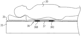
図2Bは、本発明の一実施形態による、パッド38の側面図である。パパッド38は、典型的には厚さが1.2cmのフレーム材料によって形成された薄型フレーム37を備えている。発生器36B及び36Cは(この側面図では見えない発生器36A及び36Dとともに)フレーム37上に固定される。いくつかの実施形態では、パッド38は、テーブル33と、患者30が上に横たわるマットレス35との間に位置付けられる。
FIG. 2B is a side view of
パッド38は薄型であるため、テーブル33の上でかつ患者の下方にパッドを不都合なく直接位置決めすることができる。マットレス35の使用は任意選択であってもよく、代替的な実施形態では、パッド38は、患者30に要求される平坦度及び利便性を提供するように形成されて、患者の胴体とそれぞれの発生器36A〜36Dとの直接的な接触が可能になるようにしてもよい。
Since the
パッド38を患者30(したがってカテーテル24の遠位端上の位置決めセンサー)にごく近接させると、パッドがX線に及ぼす場合がある陰影の影響が低減する。位置特定パッドの平面と直交していない角度でシステム22が患者30を照射する際に、この影響は特に顕著である。更に、位置特定パッドとカテーテルとの間がごく近接していると、遠位端の場所の測定精度が改善される場合がある。
Placing the
図3は、本発明の一実施形態による、カテーテル手技の間の同時撮像及び位置追跡の方法を概略的に図示するフローチャートである。この方法は、患者位置決め工程100において、患者30をテーブル33上で位置特定パッド38に対して位置決めすることによって開始し、パッドはテーブルと患者の胴体との間に位置決めされる。カテーテル挿入工程102において、心臓専門医は、患者の身体の中へとカテーテル24を挿入する。追跡工程104において、カテーテル手技の間、心臓専門医は、磁気位置決めシステム20を使用して、患者の心臓内の遠位端34の位置を追跡する。並行して、照射工程106において、心臓専門医は、システム22を使用して患者のROI 39を照射することを決定することができる。開示される技法は、遮られることのないROI 39の撮像を可能にし、処置実行工程108においてそれぞれの組織のアブレーションを実行するために必要なX線透視画像を心臓専門医に提供する。
FIG. 3 is a flowchart schematically illustrating a method for simultaneous imaging and position tracking during a catheter procedure, according to one embodiment of the present invention. The method begins in
上述の実施形態は、例として引用したものであり、本発明は、上記に具体的に示し、記述した内容に限定されるものではないとことが理解されるであろう。むしろ本発明の範囲は、上記に述べた様々な特徴の組み合わせ及び下位の組み合わせ、並びに上記の記述を読むことによって当業者が想到することがあり、かつ従来技術において開示されていない変形例及び修正例も含む。 It will be understood that the embodiments described above are cited by way of example, and that the present invention is not limited to what has been particularly shown and described hereinabove. Rather, the scope of the present invention is not limited to the various features and subcombinations described above, and variations and modifications that may occur to those skilled in the art upon reading the above description and are not disclosed in the prior art. Includes examples.
〔実施の態様〕
(1) 単一平面内に配置される複数の平面コイルを備える磁場発生器であって、前記コイルのうちの少なくとも2つは非同心であり、かつ互いに平行でないそれぞれの軸の周りに巻かれ、これによって互いに平行でないそれぞれの磁場を発生させる、磁場発生器。
(2) 前記磁場のうちの少なくとも2つが、相互に直交する方向に配向されている、実施態様1に記載の磁場発生器。
(3) 前記非同心コイルが前記単一平面内で隣り合って配置されている、実施態様1に記載の磁場発生器。
(4) 前記少なくとも2つのコイルが、前記それぞれの軸において配向されるそれぞれのコア、及び前記コアの周りに巻かれるそれぞれのワイヤを備える、実施態様1に記載の磁場発生器。
(5) 前記コアが炭素を含む、実施態様4に記載の磁場発生器。
Embodiment
(1) A magnetic field generator comprising a plurality of planar coils arranged in a single plane, wherein at least two of the coils are non-concentric and wound around respective axes that are not parallel to each other A magnetic field generator that generates respective magnetic fields that are not parallel to each other.
(2) The magnetic field generator according to embodiment 1, wherein at least two of the magnetic fields are oriented in directions orthogonal to each other.
(3) The magnetic field generator according to embodiment 1, wherein the non-concentric coils are arranged adjacent to each other in the single plane.
(4) The magnetic field generator according to embodiment 1, wherein the at least two coils comprise respective cores oriented in the respective axes and respective wires wound around the cores.
(5) The magnetic field generator according to embodiment 4, wherein the core includes carbon.
(6) 前記少なくとも2つのコイルのそれぞれが、6mm〜10mmの厚さを有する、実施態様1に記載の磁場発生器。
(7) 磁場発生器を生産する方法であって、
複数の平面コイルを提供することと、
前記コイルのうちの少なくとも2つが非同心であり、かつ前記コイルが互いに平行でないそれぞれの軸の周りに巻かれるように、前記平面コイルを単一平面内に配置することと、を含む方法。
(8) 前記平面コイルを配置することが、前記非同心コイルを、前記単一平面内に隣り合って配置することを含む、実施態様7に記載の方法。
(9) 前記少なくとも2つのコイルが、前記それぞれの軸において配向されたそれぞれのコア、及び前記コアの周りに巻かれるそれぞれのワイヤを備える、実施態様7に記載の方法。
(10) 前記コアが炭素を含む、実施態様9に記載の方法。
(6) The magnetic field generator according to embodiment 1, wherein each of the at least two coils has a thickness of 6 mm to 10 mm.
(7) A method for producing a magnetic field generator,
Providing a plurality of planar coils;
Placing the planar coils in a single plane such that at least two of the coils are non-concentric and the coils are wound about respective axes that are not parallel to each other.
(8) The method of embodiment 7, wherein disposing the planar coil comprises disposing the non-concentric coils adjacent in the single plane.
9. The method of embodiment 7, wherein the at least two coils comprise a respective core oriented in the respective axis and a respective wire wound around the core.
(10) The method of embodiment 9, wherein the core comprises carbon.
(11) 前記少なくとも2つのコイルのそれぞれが6mm〜10mmの厚さを有する、実施態様7に記載の方法。
(12) 磁場を発生させる方法であって、
単一平面内に配置される複数の平面コイルを備える磁場発生器を提供することであって、前記コイルのうちの少なくとも2つは非同心であり、かつ互いに平行でないそれぞれの軸の周りに巻かれる、ことと、
電流を前記複数の平面コイルの中へと流して、これによって互いに平行でないそれぞれの磁場を発生させることと、を含む方法。
(11) The method of embodiment 7, wherein each of the at least two coils has a thickness of 6 mm to 10 mm.
(12) A method of generating a magnetic field,
Providing a magnetic field generator comprising a plurality of planar coils arranged in a single plane, wherein at least two of said coils are non-concentric and wound around respective axes that are not parallel to each other. To be taken,
Passing a current into the plurality of planar coils, thereby generating respective magnetic fields that are not parallel to each other.
Claims (12)
複数の平面コイルを提供することと、
前記コイルのうちの少なくとも2つが非同心であり、かつ前記コイルが互いに平行でないそれぞれの軸の周りに巻かれるように、前記平面コイルを単一平面内に配置することと、を含む方法。 A method of producing a magnetic field generator,
Providing a plurality of planar coils;
Placing the planar coils in a single plane such that at least two of the coils are non-concentric and the coils are wound about respective axes that are not parallel to each other.
単一平面内に配置される複数の平面コイルを備える磁場発生器を提供することであって、前記コイルのうちの少なくとも2つは非同心であり、かつ互いに平行でないそれぞれの軸の周りに巻かれる、ことと、
電流を前記複数の平面コイルの中へと流して、これによって互いに平行でないそれぞれの磁場を発生させることと、を含む方法。 A method for generating a magnetic field,
Providing a magnetic field generator comprising a plurality of planar coils arranged in a single plane, wherein at least two of said coils are non-concentric and wound around respective axes that are not parallel to each other. To be taken,
Passing a current into the plurality of planar coils, thereby generating respective magnetic fields that are not parallel to each other.
Applications Claiming Priority (4)
| Application Number | Priority Date | Filing Date | Title |
|---|---|---|---|
| US14/791,667 | 2015-07-06 | ||
| US14/791,667 US20170007155A1 (en) | 2015-07-06 | 2015-07-06 | Fluoro-invisible location pad structure for cardiac procedures |
| US15/059,628 US11109774B2 (en) | 2015-07-06 | 2016-03-03 | Flat location pad using nonconcentric coils |
| US15/059,628 | 2016-03-03 |
Publications (2)
| Publication Number | Publication Date |
|---|---|
| JP2017012760A true JP2017012760A (en) | 2017-01-19 |
| JP6824649B2 JP6824649B2 (en) | 2021-02-03 |
Family
ID=56413478
Family Applications (3)
| Application Number | Title | Priority Date | Filing Date |
|---|---|---|---|
| JP2016133070A Active JP6824649B2 (en) | 2015-07-06 | 2016-07-05 | Planar positioning pad using non-concentric coils |
| JP2016133060A Expired - Fee Related JP6776027B2 (en) | 2015-07-06 | 2016-07-05 | Structure of X-ray invisible locating pad for heart surgery |
| JP2020137379A Pending JP2021006812A (en) | 2015-07-06 | 2020-08-17 | X-ray invisible position identification pad structure for cardiac surgery |
Family Applications After (2)
| Application Number | Title | Priority Date | Filing Date |
|---|---|---|---|
| JP2016133060A Expired - Fee Related JP6776027B2 (en) | 2015-07-06 | 2016-07-05 | Structure of X-ray invisible locating pad for heart surgery |
| JP2020137379A Pending JP2021006812A (en) | 2015-07-06 | 2020-08-17 | X-ray invisible position identification pad structure for cardiac surgery |
Country Status (8)
| Country | Link |
|---|---|
| US (1) | US11109774B2 (en) |
| EP (2) | EP3114996B1 (en) |
| JP (3) | JP6824649B2 (en) |
| CN (1) | CN106333750B (en) |
| AU (2) | AU2016204106A1 (en) |
| CA (2) | CA2934219A1 (en) |
| ES (2) | ES2764397T3 (en) |
| IL (2) | IL246418B (en) |
Cited By (2)
| Publication number | Priority date | Publication date | Assignee | Title |
|---|---|---|---|---|
| JP2021513417A (en) * | 2018-02-14 | 2021-05-27 | セント・ジュード・メディカル・インターナショナル・ホールディング・エスエーアールエルSt. Jude Medical International Holding S.a,r.l. | Local magnetic field transmitter |
| KR20220005878A (en) * | 2020-07-07 | 2022-01-14 | 재단법인 한국마이크로의료로봇연구원 | Bed-integrated electromagnetic field device for micro robot movement control and microrobot driving method using the same |
Families Citing this family (7)
| Publication number | Priority date | Publication date | Assignee | Title |
|---|---|---|---|---|
| US11109774B2 (en) | 2015-07-06 | 2021-09-07 | Biosense Webster (Israel) Ltd. | Flat location pad using nonconcentric coils |
| US11612437B2 (en) | 2017-05-10 | 2023-03-28 | Biosense Webster (Israel) Ltd. | Location pad with improved immunity to interference |
| US10517612B2 (en) | 2017-09-19 | 2019-12-31 | Biosense Webster (Israel) Ltd. | Nail hole guiding system |
| US20210275255A1 (en) * | 2020-03-09 | 2021-09-09 | Biosense Webster (Israel) Ltd. | Finding roll angle of distal end of deflectable or non-deflectable invasive medical instrument |
| US11832883B2 (en) | 2020-04-23 | 2023-12-05 | Johnson & Johnson Surgical Vision, Inc. | Using real-time images for augmented-reality visualization of an ophthalmology surgical tool |
| US20210330395A1 (en) * | 2020-04-23 | 2021-10-28 | Johnson & Johnson Surgical Vision, Inc. | Location pad surrounding at least part of patient eye for tracking position of a medical instrument |
| CN114557780B (en) * | 2022-03-01 | 2024-01-26 | 长春理工大学 | Three-dimensional positioning system and method for assisting surgery |
Family Cites Families (27)
| Publication number | Priority date | Publication date | Assignee | Title |
|---|---|---|---|---|
| US5307072A (en) * | 1992-07-09 | 1994-04-26 | Polhemus Incorporated | Non-concentricity compensation in position and orientation measurement systems |
| US5391199A (en) | 1993-07-20 | 1995-02-21 | Biosense, Inc. | Apparatus and method for treating cardiac arrhythmias |
| EP0776176B1 (en) | 1994-08-19 | 1999-12-29 | Biosense, Inc. | Medical diagnosis, treatment and imaging systems |
| US6690963B2 (en) | 1995-01-24 | 2004-02-10 | Biosense, Inc. | System for determining the location and orientation of an invasive medical instrument |
| DE69738274T2 (en) | 1996-02-15 | 2008-08-28 | Biosense Webster, Inc., Diamond Bar | Mobile receiving and transmitting coils for a location system |
| ES2212079T3 (en) | 1996-02-15 | 2004-07-16 | Biosense, Inc. | POSITION MARKER PROBE. |
| EP0891152B1 (en) | 1996-02-15 | 2003-11-26 | Biosense, Inc. | Independently positionable transducers for location system |
| US6239724B1 (en) | 1997-12-30 | 2001-05-29 | Remon Medical Technologies, Ltd. | System and method for telemetrically providing intrabody spatial position |
| AU1240801A (en) * | 1999-10-28 | 2001-05-08 | Enterprise Medical Technology, Inc. | Coil structures and methods for generating magnetic fields |
| US7366562B2 (en) * | 2003-10-17 | 2008-04-29 | Medtronic Navigation, Inc. | Method and apparatus for surgical navigation |
| US6484118B1 (en) | 2000-07-20 | 2002-11-19 | Biosense, Inc. | Electromagnetic position single axis system |
| US20030040670A1 (en) | 2001-06-15 | 2003-02-27 | Assaf Govari | Method for measuring temperature and of adjusting for temperature sensitivity with a medical device having a position sensor |
| US7729742B2 (en) | 2001-12-21 | 2010-06-01 | Biosense, Inc. | Wireless position sensor |
| US20040068178A1 (en) | 2002-09-17 | 2004-04-08 | Assaf Govari | High-gradient recursive locating system |
| US20040199072A1 (en) | 2003-04-01 | 2004-10-07 | Stacy Sprouse | Integrated electromagnetic navigation and patient positioning device |
| US7720521B2 (en) | 2004-04-21 | 2010-05-18 | Acclarent, Inc. | Methods and devices for performing procedures within the ear, nose, throat and paranasal sinuses |
| JP4709594B2 (en) * | 2004-08-03 | 2011-06-22 | オリンパス株式会社 | Magnetic guidance medical system |
| US20060241397A1 (en) | 2005-02-22 | 2006-10-26 | Assaf Govari | Reference pad for position sensing |
| US7835785B2 (en) * | 2005-10-04 | 2010-11-16 | Ascension Technology Corporation | DC magnetic-based position and orientation monitoring system for tracking medical instruments |
| US8798711B2 (en) * | 2006-02-09 | 2014-08-05 | Biosense Webster, Inc. | Shielding of catheter handle |
| US20070265526A1 (en) | 2006-05-11 | 2007-11-15 | Assaf Govari | Low-profile location pad |
| US8082020B2 (en) * | 2006-08-07 | 2011-12-20 | Biosense Webster, Inc. | Distortion-immune position tracking using redundant magnetic field measurements |
| US7508195B2 (en) | 2007-01-18 | 2009-03-24 | General Electric Company | Anti-distortion electromagnetic sensor method and system |
| US7782046B2 (en) * | 2007-02-05 | 2010-08-24 | General Electric Company | Electromagnetic tracking method and system |
| US8062229B2 (en) * | 2007-08-10 | 2011-11-22 | Rauscher Elizabeth A | Methods and devices for measurement and treatment of pain and the treatment of inflammation and osteoporosis |
| JP5902878B1 (en) | 2013-03-15 | 2016-04-13 | メディガイド リミテッド | Medical device guidance system |
| US11109774B2 (en) | 2015-07-06 | 2021-09-07 | Biosense Webster (Israel) Ltd. | Flat location pad using nonconcentric coils |
-
2016
- 2016-03-03 US US15/059,628 patent/US11109774B2/en active Active
- 2016-06-17 AU AU2016204106A patent/AU2016204106A1/en not_active Abandoned
- 2016-06-22 AU AU2016204257A patent/AU2016204257A1/en not_active Abandoned
- 2016-06-23 IL IL246418A patent/IL246418B/en active IP Right Grant
- 2016-06-23 IL IL246419A patent/IL246419B/en active IP Right Grant
- 2016-06-27 CA CA2934219A patent/CA2934219A1/en not_active Abandoned
- 2016-07-05 ES ES16178006T patent/ES2764397T3/en active Active
- 2016-07-05 CA CA2935278A patent/CA2935278A1/en not_active Abandoned
- 2016-07-05 JP JP2016133070A patent/JP6824649B2/en active Active
- 2016-07-05 EP EP16178006.9A patent/EP3114996B1/en active Active
- 2016-07-05 JP JP2016133060A patent/JP6776027B2/en not_active Expired - Fee Related
- 2016-07-05 EP EP16178004.4A patent/EP3114995B1/en active Active
- 2016-07-05 ES ES16178004T patent/ES2761838T3/en active Active
- 2016-07-06 CN CN201610529399.1A patent/CN106333750B/en not_active Expired - Fee Related
-
2020
- 2020-08-17 JP JP2020137379A patent/JP2021006812A/en active Pending
Cited By (4)
| Publication number | Priority date | Publication date | Assignee | Title |
|---|---|---|---|---|
| JP2021513417A (en) * | 2018-02-14 | 2021-05-27 | セント・ジュード・メディカル・インターナショナル・ホールディング・エスエーアールエルSt. Jude Medical International Holding S.a,r.l. | Local magnetic field transmitter |
| JP7073512B2 (en) | 2018-02-14 | 2022-05-23 | セント・ジュード・メディカル・インターナショナル・ホールディング・エスエーアールエル | Local magnetic field transmitter |
| KR20220005878A (en) * | 2020-07-07 | 2022-01-14 | 재단법인 한국마이크로의료로봇연구원 | Bed-integrated electromagnetic field device for micro robot movement control and microrobot driving method using the same |
| KR102379538B1 (en) | 2020-07-07 | 2022-03-28 | 재단법인 한국마이크로의료로봇연구원 | Bed-integrated electromagnetic field device for micro robot movement control and microrobot driving method using the same |
Also Published As
| Publication number | Publication date |
|---|---|
| EP3114996B1 (en) | 2019-10-09 |
| IL246418B (en) | 2020-08-31 |
| ES2761838T3 (en) | 2020-05-21 |
| JP6824649B2 (en) | 2021-02-03 |
| IL246419B (en) | 2020-04-30 |
| JP6776027B2 (en) | 2020-10-28 |
| JP2021006812A (en) | 2021-01-21 |
| EP3114996A1 (en) | 2017-01-11 |
| JP2017015708A (en) | 2017-01-19 |
| AU2016204106A1 (en) | 2017-02-02 |
| ES2764397T3 (en) | 2020-06-03 |
| CA2935278A1 (en) | 2017-01-06 |
| CA2934219A1 (en) | 2017-01-06 |
| AU2016204257A1 (en) | 2017-02-02 |
| EP3114995A1 (en) | 2017-01-11 |
| IL246418A0 (en) | 2016-11-30 |
| EP3114995B1 (en) | 2019-10-16 |
| IL246419A0 (en) | 2016-11-30 |
| CN106333750B (en) | 2021-04-02 |
| US20170007156A1 (en) | 2017-01-12 |
| US11109774B2 (en) | 2021-09-07 |
| CN106333750A (en) | 2017-01-18 |
Similar Documents
| Publication | Publication Date | Title |
|---|---|---|
| JP6824649B2 (en) | Planar positioning pad using non-concentric coils | |
| JP5820405B2 (en) | Local error compensation system in electromagnetic tracking system | |
| US8335557B2 (en) | System for carrying out and monitoring minimally-invasive interventions | |
| CN103829949B (en) | Patient motion compensation in internal probe tracking system | |
| US11771337B2 (en) | Magnetic field generator with minimal image occlusion and minimal impact on dimensions in c-arm x-ray environments | |
| US20090306497A1 (en) | Calibration method for catheter tracking system using medical imaging data | |
| EP1761901A1 (en) | A medical imaging system for mapping a structure in a patient's body | |
| US20230355129A1 (en) | MULTl-LAYER FLAT COIL MAGNETIC TRANSMITTERS | |
| EP3703605B1 (en) | Mechanical design considerations for table-mounted device used as a sub-assembly in a magnetic tracking system working in conjunction with an x-ray imaging system | |
| US20170007155A1 (en) | Fluoro-invisible location pad structure for cardiac procedures | |
| JP2023508581A (en) | Locating pads for neurosurgery | |
| US11839461B2 (en) | Localized magnetic field transmitter |
Legal Events
| Date | Code | Title | Description |
|---|---|---|---|
| A621 | Written request for application examination |
Free format text: JAPANESE INTERMEDIATE CODE: A621 Effective date: 20190603 |
|
| A977 | Report on retrieval |
Free format text: JAPANESE INTERMEDIATE CODE: A971007 Effective date: 20200807 |
|
| A131 | Notification of reasons for refusal |
Free format text: JAPANESE INTERMEDIATE CODE: A131 Effective date: 20200818 |
|
| A521 | Request for written amendment filed |
Free format text: JAPANESE INTERMEDIATE CODE: A523 Effective date: 20201028 |
|
| TRDD | Decision of grant or rejection written | ||
| A01 | Written decision to grant a patent or to grant a registration (utility model) |
Free format text: JAPANESE INTERMEDIATE CODE: A01 Effective date: 20210105 |
|
| A61 | First payment of annual fees (during grant procedure) |
Free format text: JAPANESE INTERMEDIATE CODE: A61 Effective date: 20210113 |
|
| R150 | Certificate of patent or registration of utility model |
Ref document number: 6824649 Country of ref document: JP Free format text: JAPANESE INTERMEDIATE CODE: R150 |