JP5450041B2 - Leaf spring device having eyeball part, method for manufacturing leaf spring device, and shot peening device - Google Patents
Leaf spring device having eyeball part, method for manufacturing leaf spring device, and shot peening device Download PDFInfo
- Publication number
- JP5450041B2 JP5450041B2 JP2009293414A JP2009293414A JP5450041B2 JP 5450041 B2 JP5450041 B2 JP 5450041B2 JP 2009293414 A JP2009293414 A JP 2009293414A JP 2009293414 A JP2009293414 A JP 2009293414A JP 5450041 B2 JP5450041 B2 JP 5450041B2
- Authority
- JP
- Japan
- Prior art keywords
- shot
- eyeball
- region
- leaf spring
- residual stress
- Prior art date
- Legal status (The legal status is an assumption and is not a legal conclusion. Google has not performed a legal analysis and makes no representation as to the accuracy of the status listed.)
- Active
Links
- 210000005252 bulbus oculi Anatomy 0.000 title claims description 131
- 238000005480 shot peening Methods 0.000 title claims description 69
- 238000000034 method Methods 0.000 title claims description 10
- 238000004519 manufacturing process Methods 0.000 title claims description 8
- 238000002347 injection Methods 0.000 claims description 25
- 239000007924 injection Substances 0.000 claims description 25
- 238000004804 winding Methods 0.000 claims description 16
- 238000005520 cutting process Methods 0.000 claims description 12
- 238000009826 distribution Methods 0.000 claims description 10
- 239000007921 spray Substances 0.000 claims description 6
- 230000003111 delayed effect Effects 0.000 description 12
- 230000000694 effects Effects 0.000 description 6
- 239000000725 suspension Substances 0.000 description 4
- 229910000831 Steel Inorganic materials 0.000 description 3
- 210000001508 eye Anatomy 0.000 description 3
- 238000010438 heat treatment Methods 0.000 description 3
- 239000010959 steel Substances 0.000 description 3
- 229910000639 Spring steel Inorganic materials 0.000 description 2
- QAOWNCQODCNURD-UHFFFAOYSA-N Sulfuric acid Chemical compound OS(O)(=O)=O QAOWNCQODCNURD-UHFFFAOYSA-N 0.000 description 2
- 230000012447 hatching Effects 0.000 description 2
- 239000002184 metal Substances 0.000 description 2
- 238000010791 quenching Methods 0.000 description 2
- 230000000171 quenching effect Effects 0.000 description 2
- 238000005496 tempering Methods 0.000 description 2
- 230000002378 acidificating effect Effects 0.000 description 1
- 239000012141 concentrate Substances 0.000 description 1
- 239000013013 elastic material Substances 0.000 description 1
- 238000003754 machining Methods 0.000 description 1
- 239000000463 material Substances 0.000 description 1
- 238000000465 moulding Methods 0.000 description 1
- 239000002245 particle Substances 0.000 description 1
- 239000000243 solution Substances 0.000 description 1
- 239000002436 steel type Substances 0.000 description 1
- 239000000126 substance Substances 0.000 description 1
Images


Classifications
-
- B—PERFORMING OPERATIONS; TRANSPORTING
- B24—GRINDING; POLISHING
- B24C—ABRASIVE OR RELATED BLASTING WITH PARTICULATE MATERIAL
- B24C1/00—Methods for use of abrasive blasting for producing particular effects; Use of auxiliary equipment in connection with such methods
- B24C1/10—Methods for use of abrasive blasting for producing particular effects; Use of auxiliary equipment in connection with such methods for compacting surfaces, e.g. shot-peening
-
- F—MECHANICAL ENGINEERING; LIGHTING; HEATING; WEAPONS; BLASTING
- F16—ENGINEERING ELEMENTS AND UNITS; GENERAL MEASURES FOR PRODUCING AND MAINTAINING EFFECTIVE FUNCTIONING OF MACHINES OR INSTALLATIONS; THERMAL INSULATION IN GENERAL
- F16F—SPRINGS; SHOCK-ABSORBERS; MEANS FOR DAMPING VIBRATION
- F16F1/00—Springs
- F16F1/02—Springs made of steel or other material having low internal friction; Wound, torsion, leaf, cup, ring or the like springs, the material of the spring not being relevant
- F16F1/18—Leaf springs
- F16F1/26—Attachments or mountings
-
- C—CHEMISTRY; METALLURGY
- C21—METALLURGY OF IRON
- C21D—MODIFYING THE PHYSICAL STRUCTURE OF FERROUS METALS; GENERAL DEVICES FOR HEAT TREATMENT OF FERROUS OR NON-FERROUS METALS OR ALLOYS; MAKING METAL MALLEABLE, e.g. BY DECARBURISATION OR TEMPERING
- C21D7/00—Modifying the physical properties of iron or steel by deformation
- C21D7/02—Modifying the physical properties of iron or steel by deformation by cold working
- C21D7/04—Modifying the physical properties of iron or steel by deformation by cold working of the surface
- C21D7/06—Modifying the physical properties of iron or steel by deformation by cold working of the surface by shot-peening or the like
-
- C—CHEMISTRY; METALLURGY
- C22—METALLURGY; FERROUS OR NON-FERROUS ALLOYS; TREATMENT OF ALLOYS OR NON-FERROUS METALS
- C22C—ALLOYS
- C22C38/00—Ferrous alloys, e.g. steel alloys
- C22C38/02—Ferrous alloys, e.g. steel alloys containing silicon
-
- C—CHEMISTRY; METALLURGY
- C22—METALLURGY; FERROUS OR NON-FERROUS ALLOYS; TREATMENT OF ALLOYS OR NON-FERROUS METALS
- C22C—ALLOYS
- C22C38/00—Ferrous alloys, e.g. steel alloys
- C22C38/04—Ferrous alloys, e.g. steel alloys containing manganese
-
- C—CHEMISTRY; METALLURGY
- C22—METALLURGY; FERROUS OR NON-FERROUS ALLOYS; TREATMENT OF ALLOYS OR NON-FERROUS METALS
- C22C—ALLOYS
- C22C38/00—Ferrous alloys, e.g. steel alloys
- C22C38/18—Ferrous alloys, e.g. steel alloys containing chromium
- C22C38/32—Ferrous alloys, e.g. steel alloys containing chromium with boron
-
- C—CHEMISTRY; METALLURGY
- C22—METALLURGY; FERROUS OR NON-FERROUS ALLOYS; TREATMENT OF ALLOYS OR NON-FERROUS METALS
- C22F—CHANGING THE PHYSICAL STRUCTURE OF NON-FERROUS METALS AND NON-FERROUS ALLOYS
- C22F1/00—Changing the physical structure of non-ferrous metals or alloys by heat treatment or by hot or cold working
-
- F—MECHANICAL ENGINEERING; LIGHTING; HEATING; WEAPONS; BLASTING
- F16—ENGINEERING ELEMENTS AND UNITS; GENERAL MEASURES FOR PRODUCING AND MAINTAINING EFFECTIVE FUNCTIONING OF MACHINES OR INSTALLATIONS; THERMAL INSULATION IN GENERAL
- F16F—SPRINGS; SHOCK-ABSORBERS; MEANS FOR DAMPING VIBRATION
- F16F1/00—Springs
- F16F1/02—Springs made of steel or other material having low internal friction; Wound, torsion, leaf, cup, ring or the like springs, the material of the spring not being relevant
- F16F1/18—Leaf springs
-
- C—CHEMISTRY; METALLURGY
- C21—METALLURGY OF IRON
- C21D—MODIFYING THE PHYSICAL STRUCTURE OF FERROUS METALS; GENERAL DEVICES FOR HEAT TREATMENT OF FERROUS OR NON-FERROUS METALS OR ALLOYS; MAKING METAL MALLEABLE, e.g. BY DECARBURISATION OR TEMPERING
- C21D2221/00—Treating localised areas of an article
- C21D2221/10—Differential treatment of inner with respect to outer regions, e.g. core and periphery, respectively
-
- F—MECHANICAL ENGINEERING; LIGHTING; HEATING; WEAPONS; BLASTING
- F16—ENGINEERING ELEMENTS AND UNITS; GENERAL MEASURES FOR PRODUCING AND MAINTAINING EFFECTIVE FUNCTIONING OF MACHINES OR INSTALLATIONS; THERMAL INSULATION IN GENERAL
- F16F—SPRINGS; SHOCK-ABSORBERS; MEANS FOR DAMPING VIBRATION
- F16F2226/00—Manufacturing; Treatments
- F16F2226/02—Surface treatments
Description
この発明は、車両の懸架機構等に使用される目玉部を有する板ばね装置と、板ばね装置の製造方法と、目玉部のためのショットピーニング装置に関する。 The present invention relates to a leaf spring device having an eyeball portion used for a vehicle suspension mechanism or the like, a method for manufacturing the leaf spring device, and a shot peening device for the eyeball portion.
車両の懸架機構に使用される板ばね装置は、端部に目玉部(eye)を有する鋼製の板ばねと、この板ばねの目玉部に挿入されたブッシュ等を有し、ブッシュを介して車体側の部材に取付けられている。また、板ばねの耐久性を向上させるために、ショットピーニングが行なわれている。ショットピーニングは、板ばねの表面に例えばカットワイヤ等からなる多数のショットを高速で打付けることによって、板ばねの表面に圧縮残留応力を生じさせる。また目玉部の耐久性を向上させるために、目玉部の内面にショットピーニングが行なわれることもある。 A leaf spring device used for a suspension mechanism of a vehicle has a steel leaf spring having an eyeball at its end, a bush inserted into the eyeball of the leaf spring, and the like. It is attached to the vehicle body side member. Further, shot peening is performed in order to improve the durability of the leaf spring. Shot peening generates compressive residual stress on the surface of the leaf spring by hitting a large number of shots made of, for example, cut wires on the surface of the leaf spring at high speed. In addition, shot peening may be performed on the inner surface of the eyeball portion in order to improve the durability of the eyeball portion.
例えば下記特許文献1に記載されているショットピーニング装置を用いて、目玉部の内面に圧縮残留応力を付与させることが知られている。この公知技術では、目玉部の内側にショット噴射ノズルとショット反射部材とを挿入し、ショット噴射ノズルからショット反射部材に向けてショットを投射している。ショット噴射ノズルから投射されたショットは、ショット反射部材によって反射されて目玉部の内面に当たる。またこの特許文献1には、目玉部の下部に集中的にショットピーニングを行なうことによって、目玉部の疲労破壊と遅れ破壊を抑制する旨記載されている。
For example, it is known to apply compressive residual stress to the inner surface of the eyeball using a shot peening apparatus described in
前記特許文献1の図1等に開示されているように、目玉部の内面全体にショットピーニングを行なえば目玉部の耐久性を向上させることが可能である。しかし目玉部の内面全体に均一にショットを投射すると、耐久性向上の効果が小さい領域にも多量のショットを投射することになるため、ショットピーニング時間が長くかかるだけでなく、省エネルギーの要望に反する。
As disclosed in FIG. 1 and the like of
また前記特許文献1の図9に開示されているように、目玉部の下部に集中的にショットを投射する場合には、疲労破壊を抑制する上で効果が認められても、目玉部によっては遅れ破壊を抑制する効果が小さいことがある。例えばSUP11等のばね鋼からなる高強度板ばねにおいて、目玉部に圧入されるブッシュの外径が目玉部の内径よりも0.5mm以上大きい場合に、目玉部の下部にショットピーニングを集中的に行なうだけでは、ブッシュ圧入後の遅れ破壊を抑制する上で効果が少ないことも判った。
In addition, as disclosed in FIG. 9 of
従って本発明の目的は、ブッシュが圧入された目玉部の疲労破壊と遅れ破壊を抑制することができる板ばね装置と、ショットピーニング装置と、板ばね装置の製造方法を提供することにある。 Accordingly, an object of the present invention is to provide a leaf spring device, a shot peening device, and a method for manufacturing the leaf spring device that can suppress fatigue fracture and delayed fracture of the eyeball portion into which the bush is press-fitted.
本発明の板ばね装置は、端部に丸く巻かれた目玉部を有する板ばねと、前記目玉部に圧入されるブッシュとを備えた板ばね装置であって、前記目玉部の内側に削り加工とショットピーニングとがなされた目玉内面を有し、該目玉内面が、巻き始め部を含む第1の領域と、該第1の領域に対し目玉中心を挟んで反対側に位置しかつ目玉中心を通る鉛直線上の巻き中間点を含む第2の領域と、前記第1の領域と前記第2の領域との間に形成され該目玉内面の周方向に沿う他の領域とを有し、かつ、前記目玉内面の周方向の圧縮残留応力分布に関して前記第1の領域の圧縮残留応力の絶対値と、前記第2の領域の圧縮残留応力の絶対値とが、前記他の領域の圧縮残留応力の絶対値よりも大きい圧縮残留応力分布を有している。 The leaf spring device of the present invention is a leaf spring device comprising a leaf spring having an eyeball portion rounded around an end portion and a bush pressed into the eyeball portion, and is machined inside the eyeball portion. And an inner surface of the eyeball that has been subjected to shot peening, and the inner surface of the eyeball is located on the opposite side of the first area with respect to the first area, and includes the center of the eyeball. A second region including a winding intermediate point on a vertical line passing therethrough, another region formed between the first region and the second region and extending along a circumferential direction of the inner surface of the eyeball, and the absolute value of the compressive residual stress of the first region with respect to compressive residual stress distribution in the circumferential direction of the eyeball inner surface, and the absolute value of the compressive residual stress of the second region, the compressive residual stress of the other region It has a compressive residual stress distribution larger than the absolute value.
本発明の板ばね装置の製造方法は、板ばねの端部を丸く巻くことによって、巻き始め部を含む第1の領域と、該第1の領域に対し目玉中心を挟んで反対側に位置しかつ目玉中心を通る鉛直線上の巻き中間点を含む第2の領域と、前記第1の領域と前記第2の領域との間に形成され内面の周方向に沿う他の領域とを有する目玉部を形成する工程と、前記目玉部の内面を削ることによって該目玉内面を円形に仕上げるとともに該目玉内面に付着していた酸化皮膜を除去する削り工程と、前記削り工程が行なわれた後に実施される内面ショットピーニング工程と、前記内面ショットピーニング工程後に前記目玉部に該目玉部の内径よりも大きな外径のブッシュを圧入する工程とを具備している。前記内面ショットピーニング工程では、前記目玉内面にショットを投射することによって前記目玉内面に圧縮残留応力を付与し、かつ、該目玉内面の周方向の圧縮残留応力分布に関して前記第1の領域の圧縮残留応力の絶対値と、前記第2の領域の圧縮残留応力の絶対値とを、前記他の領域の圧縮残留応力の絶対値よりも大きくしている。 The manufacturing method of the leaf spring device of the present invention is located on the opposite side of the first region including the winding start portion and the center of the center of the eyeball by winding the end of the leaf spring in a round shape . And an eyeball portion having a second region including a winding intermediate point on a vertical line passing through the center of the eyeball, and another region formed between the first region and the second region along the circumferential direction of the inner surface. And a step of cutting the inner surface of the eyeball portion to finish the inner surface of the eyeball into a circular shape and removing an oxide film adhering to the inner surface of the eyeball, and after the shaving step is performed. An inner surface shot peening step, and a step of press-fitting a bush having an outer diameter larger than the inner diameter of the eyeball portion into the eyeball portion after the inner surface shot peening step. Wherein the inner surface shot peening process, the by projecting shot centerpiece inner surface to impart compressive residual stress in the centerpiece inner surface, and compressive residual of the first region with respect to compressive residual stress distribution in the circumferential direction of the said purpose ball inside surface the absolute value of the stress, the absolute value of the compressive residual stress of the second region is made larger than the absolute value of the compressive residual stress of the other region.
前記目玉内面にショットピーニングを行うためのショットピーニング装置は、前記目玉部の内側に挿入されるショット噴射ノズルと、前記ショット噴射ノズルと対向する反射面を有し前記ショット噴射ノズルから投射されたショットを該反射面で反射させ前記目玉内面に向わせるショット反射部材とを具備し、前記反射面は、前記第1の領域と第2の領域に向って反射するショットの量が前記他の領域に向って反射するショットの量よりも多くなるような形状としている。 The shot peening apparatus for performing shot peening on the inner surface of the eyeball includes a shot injection nozzle inserted inside the eyeball portion, and a shot projected from the shot injection nozzle having a reflective surface facing the shot injection nozzle. Is reflected by the reflecting surface and directed toward the inner surface of the eyeball, and the reflecting surface reflects the amount of shot reflected toward the first region and the second region in the other region. The shape is such that it is larger than the amount of shots reflected toward.
このショットピーニング装置において、前記ショット反射部材の軸線に対する前記反射面のなす角度が、該反射面で反射するショットの投射角が0°を越えて45°以下となるような角度に設定されているとよい。 In this shot peening apparatus, the angle formed by the reflecting surface with respect to the axis of the shot reflecting member is set such that the projection angle of the shot reflected by the reflecting surface is more than 0 ° and not more than 45 °. Good.
本発明によれば、目玉部にブッシュが圧入された板ばね装置において、目玉部の疲労破壊と遅れ破壊を抑制する上で有効な箇所に圧縮残留応力を十分付与することができ、目玉部の信頼性を高めることができる。 According to the present invention, in a leaf spring device in which a bush is press-fitted into an eyeball part, it is possible to sufficiently apply compressive residual stress to an effective location for suppressing fatigue fracture and delayed fracture of the eyeball part. Reliability can be increased.
以下に本発明の第1の実施形態に係る板ばね装置と、その製造方法について、図1から図6を参照して説明する。
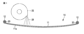
図1に示す板ばね装置10は、例えば自動車等の車両の懸架機構に使用されるものであり、両端に目玉部12を有する鋼製の板ばね11と、目玉部12に圧入されたブッシュ20とを有している。
Hereinafter, a leaf spring device according to a first embodiment of the present invention and a manufacturing method thereof will be described with reference to FIGS.
A
この板ばね11は、図示しない車両の懸架機構部に取付けられ、車両の荷重を弾性的に支持する。このため目玉部12に車両のばね上重量が負荷されるとともに、車両の加速あるいは減速時に引張の応力が目玉部12に繰返し作用する。一般的には板ばね11の厚み方向に子板(図示せず)を重ねることによって、重ね板ばね装置が構成される。
The
板ばね11の材料(ばね鋼)の一例はSUP11である。化学成分(mass%)の一例はC:0.56〜0.64、Si:0.15〜0.35、Mn:0.70〜1.00、P:0.035以下、S:0.035以下、Cr:0.70〜1.00、B:0.0005以上、残部Feである。ただしこれ以外の鋼種のばね鋼が使用されてもよい。
An example of the material (spring steel) of the
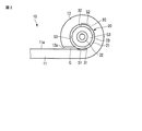
図2と図3に示すように、ブッシュ20の一例は、金属製の外筒21と、内筒22と、弾性部材23によって構成されている。弾性部材23はゴム等の弾性材料からなり、外筒21と内筒22との間に設けられている。この板ばね11には焼入れと焼戻し等の熱処理が行なわれている。
As shown in FIGS. 2 and 3, an example of the
板ばね11の両端部に設けられた一対の目玉部12間の領域が帯状のリーフ部11aとなっている。言い換えるとリーフ部11aの両端に前記目玉部12が形成されている。この実施形態の目玉部12は、リーフ部11aの両端から上側に丸く巻かれている。すなわちこの目玉部12は上巻き目玉(up-turned eye)である。目玉部12の板端12aとリーフ部11aの上面との間に若干の隙間Gが形成されている。
A region between a pair of
板ばね11の表面には、第1のショットピーニング装置25(図1に一部を模式的に示す)によって、ショットピーニングがなされている。第1のショットピーニング装置25は、板ばね11を移動させながら、高速で回転するインペラの接線方向にショット26を投射し、板ばね11の全周にショット26を打付けることによって、板ばね11の外面に圧縮残留応力を生じさせるようになっている。
Shot peening is performed on the surface of the
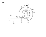
図4に示すように目玉部12の内側には、後述する削り加工とショットピーニングとがなされた目玉内面30が形成されている。目玉内面30は、目玉部12の巻き始め部31を含む第1の領域S1(図2と図4に下側のハッチングで示す部分)と、目玉中心C1を通る鉛直線V上の巻き中間点32を含む第2の領域S2(図2と図4に上側のハッチングで示す部分)とを有している。しかも第2の領域S2は、巻き中間点32から巻き始め部31側に角度θ(約20°)だけ戻った位置P1を含んでいる。第2の領域S2は、第1の領域S1に対して目玉中心C1を挟んで反対側、すなわち目玉内面30の最上部に位置している。
As shown in FIG. 4, an
図5に示すように目玉内面30は、リーマ等の切削工具40を用いた削り加工によって円形に仕上げられている。この削り加工では、切削工具40を回転させながら目玉部12に挿入する。この削り加工によって目玉内面30の真円度が高められ、かつ、目玉内面30の内径D1がブッシュ20の外径D2よりも僅かに小さく(例えばD1とD2の差が0.7mm以下)となるように目玉内面30が仕上げられている。
As shown in FIG. 5, the eyeball
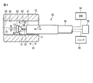
また、前記削り加工後に実施される内面ショットピーニング工程により、目玉内面30に圧縮残留応力が付与されている。内面ショットピーニング工程では、図6に示す第2のショットピーニング装置50が使用される。第2のショットピーニング装置50は、目玉部12に挿入されるショット噴射ノズル51と、ショット反射部材52と、駆動機構53と、圧縮空気の供給源54と、ショット供給源55と、ショット供給ホース56となどを備えている。ショット反射部材52は、軸57によってショット噴射ノズル51に固定されている。ショット反射部材52の反射面58はショット噴射ノズル51の噴射口と対向する位置に配置されている。駆動機構53は、ショット噴射ノズル51とショット反射部材52とを目玉部12の軸線方向(図6に矢印X1で示す方向)に移動させる機能を有している。
Further, a compressive residual stress is applied to the centerpiece
なお、ショット噴射ノズル51とショット反射部材52を固定した状態とし、目玉部12を図6に矢印X2で示す方向に相対的に移動させてもよい。要するに目玉内面30に対して、ショット反射部材52とショット噴射ノズル51とを目玉部12の軸線方向に相対移動させることができるようになっている。
Note that the
ショット反射部材52の一例は、ショット噴射ノズル51と同心に配置された三角錐形のコーン形状をなしている。ショット噴射ノズル51から投射されたショット60は、ショット反射部材52の反射面にて反射し、ショット反射部材52の径方向に向きを変えることにより、ショットが目玉内面30に投射される。例えばショットサイズ(粒径)がφ1.3mmのラウンドカットワイヤあるいはショットサイズがφ1.0mmのカットワイヤを目玉内面30に向けて高速(例えば投射速度76.7m/sec)で投射する。投射圧力の一例は0.5MPa、投射量は例えば200g/秒、投射時間は3〜30秒である。
An example of the
目玉部12を有する板ばね装置10の疲労破壊試験を行なうと、疲労破壊は主として第1の領域S1に生じることが判っている。しかし本発明者達が鋭意研究した結果、比較的大きな力でブッシュ20が圧入された目玉部12の場合、遅れ破壊に関しては第2の領域S2のショットピーニングが特に有効であるとの知見が得られた。そこで第1の領域S1以外に第2の領域S2も重点的にショットピーニングを行なうようにした。
When the fatigue failure test of the
例えば図6に示すように、第1のショットピーニング工程では、ショット噴射ノズル51とショット反射部材52の中心線C3を目玉部12の中心線C2に対してオフセット量Tだけ第1の領域S1側に片寄らせた状態で、ショット噴射ノズル51とショット反射部材52を軸線方向X1に移動させる。また第2のショットピーニング工程では、ショット噴射ノズル51とショット反射部材52を目玉部12の中心線C2に対して第2の領域S2側に片寄らせた状態で、ショット噴射ノズル51とショット反射部材52を軸線方向X1に移動させる。
For example, as shown in FIG. 6, in the first shot peening process, the center line C3 of the
このため前記第1のショットピーニング工程と第2のショットピーニング工程を実施することにより、第1および第2の領域S1,S2の圧縮残留応力を他の領域S3の圧縮残留応力よりも大きくすることができる。なお、第1の領域S1と第2の領域S2にショットが集中的に投射されるように、ショット反射部材52の形状を変えてもよい。
Therefore, by carrying out the first shot peening process and the second shot peening process, the compressive residual stress in the first and second regions S1, S2 is made larger than the compressive residual stress in the other region S3. Can do. Note that the shape of the
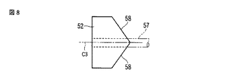
例えば図7と図8に示された第2の実施形態に係るショット反射部材52のように、2つの反射面58を形成し、各反射面58によって前記ショット60を前記第1および第2の領域S1,S2に向けて集中的に投射できるようにしてもよい。
For example, like the
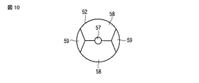
あるいは図9と図10に示された第3の実施形態のショット反射部材52のように、一対の主反射面58と一対の副反射面59とを形成し、主反射面58によって多量のショット60を第1および第2の領域S1,S2に向けて集中的に投射するとともに、副反射面59によって少量のショット60を他の領域S3に向けて投射できるようにしてもよい。
Alternatively, a pair of main reflecting
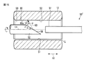
図11から図13は、第4の実施形態に係るショットピーニング装置50´を示している。このショットピーニング装置50´は、ショット噴射ノズル51とショット反射部材52とが別々に構成されている。ショット反射部材52は一対の反射面58を有しており、これら反射面58がショット噴射ノズル51と対向している。目玉部12とショット噴射ノズル51が固定されている場合、ショット反射部材52が軸線X1方向に移動する。ショット噴射ノズル51とショット反射部材52が固定されている場合には、目玉部12が矢印X2で示す方向に相対的に移動するように構成されている。それ以外は図6に示す第1の実施形態のショットピーニング装置50と同様であるため説明を省略する。
11 to 13 show a shot peening apparatus 50 'according to the fourth embodiment. In the
ショット反射部材52の軸線C3に対して反射面58のなす角度αは、ショットの投射角βが0<β≦45°となるように45°未満(α<45°)に設定されている。投射角βは、被投射面(目玉内面30)の法線Zに対してショットの投射方向がなす角度である。投射角βが45°を越えると、被投射面(目玉内面30)に衝突するショットの投射エネルギーが著しく減少するため、ショットピーニング効果が著しく低下する。
The angle α formed by the reflecting
ショットの投射角βが0°の場合には、被投射面(目玉内面30)に向うショット60が、被投射面(目玉内面30)で反射したショット60aと干渉し、ショットの投射エネルギーが相殺されるためショットピーニングの効果が著しく低下する。このため投射角βは0°以上が望ましい。ただし反射面58から目玉内面30までの距離が大きく、目玉内面30で反射するショット60aと目玉内面30に向うショット60との干渉が実質的に問題にならなければ、投射角βを0°にしてもよい。
When the shot projection angle β is 0 °, the
この実施形態の場合、図13に示すようにショット反射部材52を軸まわり(矢印Rで示す方向)に例えば0〜45°の範囲で往復回動させてもよい。こうすることにより、第1の領域S1と第2の領域S2にショットを集中させるとともに、他の領域S3にもショットを投射することができる。
In the case of this embodiment, as shown in FIG. 13, the
あるいは図14に示す第5の実施形態のショット反射部材52のように、一対の主反射面58と一対の副反射面59とを形成し、主反射面58によって多量のショット60を第1および第2の領域S1,S2に向けて集中的に投射するとともに、副反射面59によって少量のショット60を他の領域S3に向けて投射できるようにしてもよい。
Alternatively, as in the
図15は第6の実施形態に係るショットピーニング装置50”を示している。このショットピーニング装置50”のショット反射部材52には、1面傾斜タイプの反射面58が形成されている。この反射面58の角度α(軸線C3に対する反射面58の角度α)は、被投射面(目玉内面30)の法線Zに対するショットの投射角βが0<β≦45°となるように45°未満に設定されている。また反射面58の面積はショット噴射ノズル51のショット投射面積よりも大きい。この場合、ショット反射部材52を軸線C3まわりに回転させることにより、ショット噴射ノズル51に対する軸線C3のずれをある程度吸収することができる。さらに、第1および第2の領域S1,S2のように圧縮残留応力を大きくしたい箇所に対しては回転速度を遅くしてショットピーニングを重点的に行い、他の領域S3では回転速度を早くして短時間のショットピーニングを行うことにより、目玉内面30の周方向に所望の圧縮残留応力分布を付与してもよい。それ以外の構成と作用は図11のショットピーニング装置50と同様であるため説明を省略する。
FIG. 15 shows a
前記板ばね装置10の目玉部12は、その成形時に加熱されるため、表面に黒皮と呼ばれる酸化皮膜が生じている。目玉内面30に前記削り加工を行わずに黒皮が残った状態でショットピーニングを行った場合の圧縮残留応力を測定したところ、第1の領域S1の圧縮残留応力が−408MPaであった。これに対し、目玉内面30に前記削り加工を行って黒皮を除去した状態でショットピーニングを行った場合は−498MPaであり、絶対値で90MPaほど高い値が得られていることが判った。なお、当業界の慣例として圧縮残留応力値はマイナスで表わしている。このように目玉部12に削り加工を行ったのち内面ショットピーニングを実施したことにより、第1および第2の領域S1,S2の圧縮残留応力をより効果的に発現させることが可能となった。
Since the
前記内面ショットピーニング工程によって付与される目玉内面30の周方向の圧縮残留応力分布は、第1の領域S1の圧縮残留応力の絶対値と、第2の領域S2の圧縮残留応力の絶対値とが、周方向の他の領域S3の圧縮残留応力の絶対値よりも例えば5〜10%以上大きくなるようにしている。例えば第1および第2の領域S1,S2の圧縮残留応力は−498MPa以上であり、他の領域S3の圧縮残留応力は−400MPa前後である。なお、圧縮残留応力分布の勾配が急になると、勾配が急な箇所が破損の起点になることがあるため、圧縮残留応力分布の勾配を緩やかにするとよい。
The distribution of compressive residual stress in the circumferential direction of the
このように第2の領域S2の圧縮残留応力値を高めたことにより、ブッシュ20が圧入された状態での目玉部12の遅れ破壊を改善することができた。この目玉部12の遅れ破壊を調べるために、ブッシュ相当金具が圧入された目玉部12を強酸性(pH1.0)の硫酸液中に浸漬するという試験条件で遅れ破壊試験を行なった。その結果、従来の目玉部では短時間(10分〜30分)で遅れ破壊が生じていたのに対し、本実施形態の目玉部12の遅れ破壊は5時間以上で発生し、遅れ破壊が大幅に改善されることが確認された、しかも本実施形態の内面ショットピーニング工程によれば、目玉内面30の全周に均等にショットを投射する場合と比較して、投射に必要なエネルギーを節約することができた。
Thus, by increasing the compressive residual stress value in the second region S2, it was possible to improve the delayed fracture of the
前記内面ショットピーニング工程が終了したのち、目玉部12にブッシュ20が圧入される。ブッシュ20の外径D2(図2に示す)は、ブッシュ20が挿入される前の自由状態における目玉部12の内径D1よりも僅かに大きい。D1とD2の差は例えば0.5〜0.7mm程度である。従ってこの目玉部12は、ブッシュ20が圧入された状態において、前記自由状態よりも僅かに拡径した状態で目玉部12の内側に収容される。
After the inner surface shot peening process is finished, the
目玉内面30は、ブッシュ20が圧入される前に予め前記削り工程が行なわれているため、目玉内面30の真円度と表面精度が高められている。しかも前記削り工程によって、目玉部12の内径D1がブッシュ20の外径D2よりも僅かに大きくなるように仕上げられている。このためブッシュ20の全周を目玉内面30に高精度に密着させることができる。
The eyeball
以上説明したように、本実施形態の板ばね装置10の製造方法は下記の工程を含んでいる。
(1)板ばね11の端部を加熱し、丸く巻くことによって目玉部12を形成する工程。
(2)板ばね11に焼入れ、焼戻し等の熱処理を行う工程。
(3)板ばね11の外面にショットピーニングを行なう工程。
(4)目玉内面30をリーマ等によって機械加工する削り工程。この削り工程によって、目玉内面30を円形に仕上げるとともに、目玉内面30の酸化皮膜が除去される。
(5)前記削り工程が行なわれた後に、目玉内面30にショットを投射する内面ショットピーニング工程。この内面ショットピーニング工程では、第1および第2の領域S1,S2の圧縮残留応力の絶対値が他の領域S3の圧縮残留応力の絶対値よりも大きくなるように圧縮残留応力分布を生じさせる。
(6)前記内面ショットピーニング工程後にブッシュ20を目玉部12に圧入する工程。
As described above, the manufacturing method of the
(1) The process of forming the
(2) A step of performing heat treatment such as quenching and tempering on the
(3) A step of performing shot peening on the outer surface of the
(4) A shaving process of machining the
(5) An inner surface shot peening process in which a shot is projected onto the eyeball
(6) A step of press-fitting the
なお本発明を実施するに当たり、板ばねのリーフ部や目玉部、ブッシュの形状、構造をはじめとして、板ばね装置を構成する各部の態様を種々に変更して実施できることは言うまでもない。また目玉部は前記実施形態で説明したような上巻き目玉(up-turned eye)に限ることなく、下巻き目玉(down-turned eye)であってもよい。 Needless to say, in carrying out the present invention, the shape of the leaf spring, the centerpiece, the bush, and the shape and structure of the leaf spring can be variously changed. Further, the eyeball portion is not limited to the up-turned eye as described in the above embodiment, but may be a down-turned eye.
10…板ばね装置
11…板ばね
12…目玉部
20…ブッシュ
30…目玉内面
31…巻き始め部
32…巻き中間点
50,50´,50”…ショットピーニング装置
51…ショット噴射ノズル
52…ショット反射部材
58…反射面
DESCRIPTION OF
Claims (5)
前記目玉部に圧入されるブッシュとを備えた板ばね装置であって、
前記目玉部の内側に削り加工とショットピーニングとがなされた目玉内面を有し、該目玉内面が、巻き始め部を含む第1の領域と、該第1の領域に対し目玉中心を挟んで反対側に位置しかつ目玉中心を通る鉛直線上の巻き中間点を含む第2の領域と、前記第1の領域と前記第2の領域との間に形成され該目玉内面の周方向に沿う他の領域とを有し、かつ、
前記目玉内面の周方向の圧縮残留応力分布に関して前記第1の領域の圧縮残留応力の絶対値と、前記第2の領域の圧縮残留応力の絶対値とが、前記他の領域の圧縮残留応力の絶対値よりも大きい圧縮残留応力分布を有していることを特徴とする板ばね装置。 A leaf spring having an eyeball rolled round at the end;
A leaf spring device comprising a bush press-fitted into the eyeball part,
The inside of the eyeball portion has an inner surface of the eyeball that has been subjected to cutting and shot peening, and the inner surface of the eyeball is opposite to the first region including the winding start portion and the center of the eyeball with respect to the first region. A second region including a winding middle point on a vertical line passing through the center of the eyeball and the other region along the circumferential direction of the inner surface of the eyeball formed between the first region and the second region An area, and
The absolute value of the compressive residual stress of the first region with respect to compressive residual stress distribution in the circumferential direction of the eyeball inner surface, and the absolute value of the compressive residual stress of the second region, the compressive residual stress of the other region A leaf spring device having a compressive residual stress distribution larger than an absolute value.
前記目玉部の内面を削ることによって該目玉内面を円形に仕上げるとともに該目玉内面に付着していた酸化皮膜を除去する削り工程と、
前記削り工程が行なわれた後に、前記目玉内面にショットを投射することによって前記目玉内面に圧縮残留応力を付与し、かつ、該目玉内面の周方向の圧縮残留応力分布に関して前記第1の領域の圧縮残留応力の絶対値と、前記第2の領域の圧縮残留応力の絶対値とを、前記他の領域の圧縮残留応力の絶対値よりも大きくする内面ショットピーニング工程と、
前記内面ショットピーニング工程後に前記目玉部に該目玉部の内径よりも大きな外径のブッシュを圧入する工程と、
を具備したことを特徴とする板ばね装置の製造方法。 By winding the end of the leaf spring in a round shape , the first region including the winding start portion, and the winding intermediate point on the vertical line that is located on the opposite side of the first region across the center of the eyeball and passes through the center of the eyeball Forming a center part having a second region including: and another region formed between the first region and the second region along the circumferential direction of the inner surface ;
Sharpening the inner surface of the eyeball part by rounding the inner surface of the eyeball part and removing the oxide film adhering to the inner surface of the eyeball,
After the cutting process has been performed, the grant compressive residual stress in the centerpiece inner surface by projecting shot to the centerpiece inner surface, and said purpose ball inside surface circumferential direction of the first region with respect to compressive residual stress distribution in the the absolute value of the compressive residual stress, and the second the absolute value of the compressive residual stress in the region, the inner surface shot peening process to be larger than the absolute value of the compressive residual stress of the other regions,
A step of press-fitting a bush having an outer diameter larger than the inner diameter of the eyeball portion into the eyeball portion after the inner surface shot peening step;
A method for manufacturing a leaf spring device.
前記目玉部の内側に挿入されるショット噴射ノズルと、
前記ショット噴射ノズルと対向する反射面を有し前記ショット噴射ノズルから投射されたショットを該反射面で反射させ前記目玉内面に向わせるショット反射部材とを具備し、
前記反射面は、前記第1の領域と第2の領域に向って反射するショットの量が前記他の領域に向って反射するショットの量よりも多くなるような形状としたことを特徴とするショットピーニング装置。 A shot peening apparatus for performing the shot peening on the inner surface of the center of the leaf spring apparatus according to claim 1,
A shot spray nozzle inserted inside the centerpiece,
A shot reflecting member having a reflecting surface facing the shot spray nozzle and reflecting the shot projected from the shot spray nozzle on the reflecting surface and facing the inner surface of the eyeball;
The reflection surface is shaped so that the amount of shots reflected toward the first region and the second region is larger than the amount of shots reflected toward the other region. Shot peening equipment.
Priority Applications (7)
| Application Number | Priority Date | Filing Date | Title |
|---|---|---|---|
| JP2009293414A JP5450041B2 (en) | 2009-12-24 | 2009-12-24 | Leaf spring device having eyeball part, method for manufacturing leaf spring device, and shot peening device |
| MYPI2012002420A MY156148A (en) | 2009-12-24 | 2010-12-13 | Leaf spring device having eye, leaf spring device manufacturing method, and shot peening apparatus |
| PCT/JP2010/072357 WO2011077985A1 (en) | 2009-12-24 | 2010-12-13 | Leaf spring device having eye, leaf spring device manufacturing method, and shot peening apparatus |
| IN4873DEN2012 IN2012DN04873A (en) | 2009-12-24 | 2010-12-13 | |
| MX2012007278A MX346419B (en) | 2009-12-24 | 2010-12-13 | Leaf spring device having eye, leaf spring device manufacturing method, and shot peening apparatus. |
| KR1020127016138A KR101412288B1 (en) | 2009-12-24 | 2010-12-13 | Leaf spring device having eye, leaf spring device manufacturing method, and shot peening apparatus |
| CN201080058726.0A CN102666016B (en) | 2009-12-24 | 2010-12-13 | Leaf spring device having eye, leaf spring device manufacturing method, and shot peening apparatus |
Applications Claiming Priority (1)
| Application Number | Priority Date | Filing Date | Title |
|---|---|---|---|
| JP2009293414A JP5450041B2 (en) | 2009-12-24 | 2009-12-24 | Leaf spring device having eyeball part, method for manufacturing leaf spring device, and shot peening device |
Publications (2)
| Publication Number | Publication Date |
|---|---|
| JP2011131338A JP2011131338A (en) | 2011-07-07 |
| JP5450041B2 true JP5450041B2 (en) | 2014-03-26 |
Family
ID=44195515
Family Applications (1)
| Application Number | Title | Priority Date | Filing Date |
|---|---|---|---|
| JP2009293414A Active JP5450041B2 (en) | 2009-12-24 | 2009-12-24 | Leaf spring device having eyeball part, method for manufacturing leaf spring device, and shot peening device |
Country Status (7)
| Country | Link |
|---|---|
| JP (1) | JP5450041B2 (en) |
| KR (1) | KR101412288B1 (en) |
| CN (1) | CN102666016B (en) |
| IN (1) | IN2012DN04873A (en) |
| MX (1) | MX346419B (en) |
| MY (1) | MY156148A (en) |
| WO (1) | WO2011077985A1 (en) |
Families Citing this family (6)
| Publication number | Priority date | Publication date | Assignee | Title |
|---|---|---|---|---|
| JP6007097B2 (en) * | 2012-12-20 | 2016-10-12 | 日本発條株式会社 | Suspension spring device and suspension coil spring |
| CN103453059A (en) * | 2013-07-31 | 2013-12-18 | 漯河君叁材料高科有限公司 | Composite plate spring with open integrated eye |
| WO2015181916A1 (en) | 2014-05-28 | 2015-12-03 | 日本発條株式会社 | Suspension spring device and suspension coil spring |
| JP6601436B2 (en) * | 2017-02-15 | 2019-11-06 | トヨタ自動車株式会社 | Leaf spring with bush |
| AT520621B1 (en) * | 2017-10-16 | 2023-04-15 | Hendrickson Comm Vehicle Sys Europe Gmbh | Spring leaf and method of manufacturing a spring leaf |
| US11293738B2 (en) | 2018-12-31 | 2022-04-05 | Apex Brands, Inc. | Method and apparatus for providing a measuring tape with increased cupping |
Family Cites Families (7)
| Publication number | Priority date | Publication date | Assignee | Title |
|---|---|---|---|---|
| JPH0529557Y2 (en) * | 1987-05-29 | 1993-07-28 | ||
| JPS6478763A (en) * | 1987-09-15 | 1989-03-24 | Hino Motors Ltd | Processing method for plate spring eye |
| JPH0736982B2 (en) * | 1991-11-18 | 1995-04-26 | 日本発条株式会社 | Shot peening equipment for leaf spring centerpiece |
| CN2207474Y (en) * | 1994-12-30 | 1995-09-13 | 卢汝洪 | T-shape steel plate spring |
| JP2002120153A (en) * | 2000-10-13 | 2002-04-23 | Hitachi Ltd | Shot peening device |
| JP4059421B2 (en) * | 2000-10-31 | 2008-03-12 | 新東工業株式会社 | Shot pinning device |
| CN2586847Y (en) * | 2002-09-28 | 2003-11-19 | 郑州大新科贸有限公司 | Trailer series variable cross-section variable steel-degree band spring |
-
2009
- 2009-12-24 JP JP2009293414A patent/JP5450041B2/en active Active
-
2010
- 2010-12-13 IN IN4873DEN2012 patent/IN2012DN04873A/en unknown
- 2010-12-13 MX MX2012007278A patent/MX346419B/en active IP Right Grant
- 2010-12-13 WO PCT/JP2010/072357 patent/WO2011077985A1/en active Application Filing
- 2010-12-13 CN CN201080058726.0A patent/CN102666016B/en active Active
- 2010-12-13 MY MYPI2012002420A patent/MY156148A/en unknown
- 2010-12-13 KR KR1020127016138A patent/KR101412288B1/en active IP Right Grant
Also Published As
| Publication number | Publication date |
|---|---|
| MY156148A (en) | 2016-01-15 |
| MX2012007278A (en) | 2012-07-20 |
| MX346419B (en) | 2017-03-21 |
| WO2011077985A1 (en) | 2011-06-30 |
| IN2012DN04873A (en) | 2015-09-25 |
| KR20120085327A (en) | 2012-07-31 |
| JP2011131338A (en) | 2011-07-07 |
| CN102666016A (en) | 2012-09-12 |
| CN102666016B (en) | 2014-12-03 |
| KR101412288B1 (en) | 2014-06-25 |
Similar Documents
| Publication | Publication Date | Title |
|---|---|---|
| JP5450041B2 (en) | Leaf spring device having eyeball part, method for manufacturing leaf spring device, and shot peening device | |
| US10583706B2 (en) | Method of manufacturing a suspension coil spring | |
| US11285776B2 (en) | Hollow spring member and manufacturing method therefor | |
| US11701943B2 (en) | Method of manufacturing a hollow spring member | |
| JP6797922B2 (en) | How to manufacture vehicle springs | |
| JP5339540B2 (en) | Hollow coil spring and manufacturing method thereof | |
| WO2011155283A1 (en) | Method for manufacturing leaf springs | |
| JP5188445B2 (en) | Coil spring manufacturing method and coil spring | |
| WO2021192912A1 (en) | Method for determining propelling condition for shot media, and method for manufacturing coil spring | |
| KR102181670B1 (en) | Manufacturing Method of Coil-Spring for Car Suspension | |
| CN114423963A (en) | Method for manufacturing coil spring and suspension device for saddle-ride type vehicle | |
| CN106536692A (en) | Anti-galling method for treating materials |
Legal Events
| Date | Code | Title | Description |
|---|---|---|---|
| A621 | Written request for application examination |
Free format text: JAPANESE INTERMEDIATE CODE: A621 Effective date: 20120606 |
|
| RD02 | Notification of acceptance of power of attorney |
Free format text: JAPANESE INTERMEDIATE CODE: A7422 Effective date: 20130808 |
|
| A131 | Notification of reasons for refusal |
Free format text: JAPANESE INTERMEDIATE CODE: A131 Effective date: 20130910 |
|
| A521 | Request for written amendment filed |
Free format text: JAPANESE INTERMEDIATE CODE: A523 Effective date: 20131025 |
|
| RD02 | Notification of acceptance of power of attorney |
Free format text: JAPANESE INTERMEDIATE CODE: A7422 Effective date: 20131025 |
|
| A521 | Request for written amendment filed |
Free format text: JAPANESE INTERMEDIATE CODE: A821 Effective date: 20131025 |
|
| TRDD | Decision of grant or rejection written | ||
| A01 | Written decision to grant a patent or to grant a registration (utility model) |
Free format text: JAPANESE INTERMEDIATE CODE: A01 Effective date: 20131203 |
|
| A61 | First payment of annual fees (during grant procedure) |
Free format text: JAPANESE INTERMEDIATE CODE: A61 Effective date: 20131225 |
|
| R150 | Certificate of patent or registration of utility model |
Ref document number: 5450041 Country of ref document: JP Free format text: JAPANESE INTERMEDIATE CODE: R150 Free format text: JAPANESE INTERMEDIATE CODE: R150 |
|
| R250 | Receipt of annual fees |
Free format text: JAPANESE INTERMEDIATE CODE: R250 |
|
| R250 | Receipt of annual fees |
Free format text: JAPANESE INTERMEDIATE CODE: R250 |
|
| R250 | Receipt of annual fees |
Free format text: JAPANESE INTERMEDIATE CODE: R250 |
|
| R250 | Receipt of annual fees |
Free format text: JAPANESE INTERMEDIATE CODE: R250 |
|
| R250 | Receipt of annual fees |
Free format text: JAPANESE INTERMEDIATE CODE: R250 |
|
| R250 | Receipt of annual fees |
Free format text: JAPANESE INTERMEDIATE CODE: R250 |
|
| R250 | Receipt of annual fees |
Free format text: JAPANESE INTERMEDIATE CODE: R250 |
|
| R250 | Receipt of annual fees |
Free format text: JAPANESE INTERMEDIATE CODE: R250 |