JP5448568B2 - Work machine with safety device - Google Patents
Work machine with safety device Download PDFInfo
- Publication number
- JP5448568B2 JP5448568B2 JP2009123599A JP2009123599A JP5448568B2 JP 5448568 B2 JP5448568 B2 JP 5448568B2 JP 2009123599 A JP2009123599 A JP 2009123599A JP 2009123599 A JP2009123599 A JP 2009123599A JP 5448568 B2 JP5448568 B2 JP 5448568B2
- Authority
- JP
- Japan
- Prior art keywords
- acceleration sensor
- safety device
- engine
- work machine
- drive source
- Prior art date
- Legal status (The legal status is an assumption and is not a legal conclusion. Google has not performed a legal analysis and makes no representation as to the accuracy of the status listed.)
- Active
Links
- 230000001133 acceleration Effects 0.000 claims description 180
- 238000001514 detection method Methods 0.000 claims description 78
- 238000002485 combustion reaction Methods 0.000 claims description 31
- 238000005259 measurement Methods 0.000 description 19
- 230000035945 sensitivity Effects 0.000 description 16
- 230000005540 biological transmission Effects 0.000 description 11
- 238000010586 diagram Methods 0.000 description 7
- 230000006870 function Effects 0.000 description 7
- 230000007246 mechanism Effects 0.000 description 6
- 239000007858 starting material Substances 0.000 description 6
- 230000008901 benefit Effects 0.000 description 4
- 230000008859 change Effects 0.000 description 3
- 230000007423 decrease Effects 0.000 description 3
- 239000000446 fuel Substances 0.000 description 3
- 239000002828 fuel tank Substances 0.000 description 3
- 239000004065 semiconductor Substances 0.000 description 3
- 230000035939 shock Effects 0.000 description 3
- 238000013016 damping Methods 0.000 description 2
- 238000006073 displacement reaction Methods 0.000 description 2
- 238000012986 modification Methods 0.000 description 2
- 230000004048 modification Effects 0.000 description 2
- 238000011144 upstream manufacturing Methods 0.000 description 2
- 125000002066 L-histidyl group Chemical group [H]N1C([H])=NC(C([H])([H])[C@](C(=O)[*])([H])N([H])[H])=C1[H] 0.000 description 1
- 238000013459 approach Methods 0.000 description 1
- 239000000919 ceramic Substances 0.000 description 1
- 238000004891 communication Methods 0.000 description 1
- 238000013461 design Methods 0.000 description 1
- 230000007274 generation of a signal involved in cell-cell signaling Effects 0.000 description 1
- 238000009434 installation Methods 0.000 description 1
- 230000007257 malfunction Effects 0.000 description 1
- 239000002184 metal Substances 0.000 description 1
- 238000000034 method Methods 0.000 description 1
- 238000012545 processing Methods 0.000 description 1
- 230000009467 reduction Effects 0.000 description 1
- 239000011435 rock Substances 0.000 description 1
- 239000004575 stone Substances 0.000 description 1
- 238000012360 testing method Methods 0.000 description 1
Images


Classifications
-
- A—HUMAN NECESSITIES
- A01—AGRICULTURE; FORESTRY; ANIMAL HUSBANDRY; HUNTING; TRAPPING; FISHING
- A01D—HARVESTING; MOWING
- A01D34/00—Mowers; Mowing apparatus of harvesters
- A01D34/01—Mowers; Mowing apparatus of harvesters characterised by features relating to the type of cutting apparatus
- A01D34/412—Mowers; Mowing apparatus of harvesters characterised by features relating to the type of cutting apparatus having rotating cutters
- A01D34/63—Mowers; Mowing apparatus of harvesters characterised by features relating to the type of cutting apparatus having rotating cutters having cutters rotating about a vertical axis
- A01D34/82—Other details
- A01D34/828—Safety devices
-
- A—HUMAN NECESSITIES
- A01—AGRICULTURE; FORESTRY; ANIMAL HUSBANDRY; HUNTING; TRAPPING; FISHING
- A01D—HARVESTING; MOWING
- A01D75/00—Accessories for harvesters or mowers
- A01D75/20—Devices for protecting men or animals
-
- A—HUMAN NECESSITIES
- A01—AGRICULTURE; FORESTRY; ANIMAL HUSBANDRY; HUNTING; TRAPPING; FISHING
- A01D—HARVESTING; MOWING
- A01D75/00—Accessories for harvesters or mowers
- A01D75/20—Devices for protecting men or animals
- A01D75/206—Devices for protecting men or animals for mowers carried by operator
-
- F—MECHANICAL ENGINEERING; LIGHTING; HEATING; WEAPONS; BLASTING
- F16—ENGINEERING ELEMENTS AND UNITS; GENERAL MEASURES FOR PRODUCING AND MAINTAINING EFFECTIVE FUNCTIONING OF MACHINES OR INSTALLATIONS; THERMAL INSULATION IN GENERAL
- F16P—SAFETY DEVICES IN GENERAL; SAFETY DEVICES FOR PRESSES
- F16P3/00—Safety devices acting in conjunction with the control or operation of a machine; Control arrangements requiring the simultaneous use of two or more parts of the body
- F16P3/008—Devices for directly stopping or interrupting the drive or gear in case of danger to the machine, e.g. devices with clutches
-
- Y—GENERAL TAGGING OF NEW TECHNOLOGICAL DEVELOPMENTS; GENERAL TAGGING OF CROSS-SECTIONAL TECHNOLOGIES SPANNING OVER SEVERAL SECTIONS OF THE IPC; TECHNICAL SUBJECTS COVERED BY FORMER USPC CROSS-REFERENCE ART COLLECTIONS [XRACs] AND DIGESTS
- Y10—TECHNICAL SUBJECTS COVERED BY FORMER USPC
- Y10T—TECHNICAL SUBJECTS COVERED BY FORMER US CLASSIFICATION
- Y10T83/00—Cutting
- Y10T83/081—With randomly actuated stopping means
- Y10T83/088—Responsive to tool detector or work-feed-means detector
- Y10T83/089—Responsive to tool characteristic
Landscapes
- Life Sciences & Earth Sciences (AREA)
- Environmental Sciences (AREA)
- Engineering & Computer Science (AREA)
- General Engineering & Computer Science (AREA)
- Mechanical Engineering (AREA)
- Harvester Elements (AREA)
Description
本発明は、刈払機、チェーンソー、ヘッジトリマなどの刃物を備えた小型の室外作業機に関し、より詳しくは、内燃エンジンを動力源とする作業機の作業中の安全性を確保するための安全装置を備えた作業機に関する。 The present invention relates to a small outdoor work machine equipped with cutting tools such as a brush cutter, a chain saw, a hedge trimmer, and more specifically, a safety device for ensuring safety during work of a work machine using an internal combustion engine as a power source. The present invention relates to a working machine provided.
小型の内燃エンジン、典型的には単気筒のエンジンを搭載した手持ち作業機として、草刈りを対象にした刈払機、樹木の伐採を対象にしたチェーンソー、垣根を整えるためのヘッジトリマが知られている。刈払機、チェーンソー等は高速で動作する刈刃を備えた作業具であることから、作業中に予期しない状況が発生したときに刃物から作業者の安全を確保する安全装置を備えた作業機が開発されている。 As a hand-held work machine equipped with a small internal combustion engine, typically a single-cylinder engine, a brush cutter intended for mowing, a chainsaw intended for cutting a tree, and a hedge trimmer for adjusting a fence are known. Since brush cutters, chainsaws, etc. are work tools equipped with cutting blades that operate at high speed, work machines equipped with safety devices that ensure the safety of workers from the blades when unexpected situations occur during work. Has been developed.
特許文献1は、肩掛けベルト式の刈払機つまり手持ち刈払機の左右のハンドルに、夫々、作業者が把持することにより動作する停止レバーを設け、この左右の停止レバーの少なくともいずれか一方が解除されたときには、この停止レバーに機械的に連係された燃料バルブを閉じて、エンジンへの燃料供給を強制的に停止する又は点火プラグへの電源供給を強制的に停止することを開示している。 In Patent Document 1, stop levers that operate when the operator grips are provided on the left and right handles of a shoulder belt type brush cutter, that is, a hand-held brush cutter, and at least one of the left and right stop levers is released. In this case, it is disclosed that the fuel valve mechanically linked to the stop lever is closed to forcibly stop the fuel supply to the engine or to forcibly stop the power supply to the spark plug.
特許文献2は、肩掛けベルト式の刈払機において、ハンドルに停止レバー又は圧力センサを設け、この作業者がハンドルから手を離したときには、電磁式のブレーキ又は機械式のストッパが動作して刈刃の動作を強制的に制動することを開示している。
In
特許文献3は、駆動源と刈刃とを機械的に連結する動力伝達軸との間に介装した遠心クラッチを有する肩掛けベルト式の刈払機つまり手持ち刈払機において、この遠心クラッチにクラッチシューを設け、駆動源と動力伝達軸との間に大きな相対変位が有ったときには、この相対変位によって機械的に動作するクラッチシューによって自動的に遠心クラッチを制動することを開示している。 In Patent Document 3, a shoulder belt type brush cutter having a centrifugal clutch interposed between a driving source and a power transmission shaft that mechanically connects a cutting blade, that is, a hand-held brush cutter, a clutch shoe is attached to the centrifugal clutch. It is disclosed that when there is a large relative displacement between the drive source and the power transmission shaft, the centrifugal clutch is automatically braked by a clutch shoe that is mechanically operated by this relative displacement.
特許文献4は、肩掛けベルト式の刈払機において、この刈払機を肩掛けする紐の先端に取り付けられたキャップを、刈払機側のスイッチ本体に係脱自在に設けることを提案している。この肩掛けベルト式の刈払機にあっては、刈刃が大きな石などに当たって刈払機が跳ね返されるキックバック現象が発生してキャップがスイッチ本体から離脱すると、点火プラグへの電源供給が強制的に停止されてエンジンの動作が停止される。
特許文献5は手持ち式の刈払機を開示しており、この刈払機は、駆動源であるモータ又はエンジンと刈刃との間の動力伝達軸を包囲する操作チューブの周方向の一部と当接する圧電素子からなる衝撃センサを有し、この衝撃センサが所定値以上の衝撃を検出したときに電動モータ又はエンジンを強制停止させることを開示している。具体的には、操作チューブの長手方向中央部分に固定されたハンドルの近傍に、操作チューブを包囲するボックスが取り付けられ、このボックスに設置した衝撃センサは操作チューブと当接した状態で位置決めされる。なお、この特許文献3は、衝撃センサ(圧電素子)を含む安全装置に、衝撃センサに流れる電流を調整するための可変抵抗を設けることで、圧電素子の個体差による感度の不均一を解消することを提案している。
従来の安全装置のうち、例えば特許文献1、2のように、安全装置が作動する条件として、ハンドルの停止レバー又は圧力センサから手を離すことを条件とした安全装置では、作業者は常にこの条件を意識し続ける必要がある。しかし、例えば作業中の転倒を想定すると、作業者は転倒の方に気を取られてしまうのが通常であり、ハンドルから手を離すことを忘れてしまう、または、ハンドルから手を離すことができない状況である場合も考えられる。刈払機やチェーンソーなどは刃物を備えた動力付き作業機であることから、作業者がどのような状況下に追い込まれるかも知れず、したがって、この種の作業機の安全装置は作業者の操作に依存しない装置であるのが望ましい。
Among conventional safety devices, as in the case of
特許文献5に開示の圧電素子からなる衝撃センサを用いた安全装置は作業者の操作に依存していない。しかし、この特許文献5の安全装置は、前述したように、駆動源から動力を刈刃に伝える動力伝達軸を包囲する操作チューブ(メインチューブ)のハンドル部分にボックスを設置し、このボックスに取り付けた圧電素子(センサ)によって操作チューブの軸ブレを検知する構成が採用されている。したがって、特許文献5の安全装置は、圧電素子と操作チューブとの間の接触圧を検知する構成であり、操作チューブからの入力を正確に受けるには、圧電素子を支持するボックスの剛性を高める必要がある。また、操作チューブの円周方向のどの部分に圧電素子を設置するかによって、圧電素子の感度が左右される。例えば、操作チューブの上下振動に対して圧電素子を反応させるのであれば、操作チューブの上面又は下面に圧電素子を設置する必要があり、操作チューブの左右振動に対して圧電素子を反応させるのであれば、操作チューブの左面又は右面に圧電素子を設置する必要がある。
The safety device using the impact sensor composed of the piezoelectric element disclosed in
したがって、特許文献5の安全装置にあっては、接触式の衝撃センサを採用したことに伴って、これを設置するためのボックスを強固に設計する必要があり、このことは作業機の重量が増加する要因となる。更に、接触式の衝撃センサは、操作チューブの円周方向のどの部位に設置するかに関する設置場所の選定が難しい。
Therefore, in the safety device of
上記圧電式の衝撃センサに置換可能な機構として、例えば自動車のエアバッグ機構を動作させるための機械式の衝撃検知スイッチが考えられる。JP特開2006−172984号公報は、ポータブルコンピュータのハードディスクが、ポータブルコンピュータの落下による衝撃で損傷するのを防止するために、落下を検出するセンサとして、片持ちコイルバネの自由端に設けられた錘と、この錘を包囲する筒体との組み合わせからなる落下検知スイッチを開示している。 As a mechanism that can be replaced by the piezoelectric impact sensor, for example, a mechanical impact detection switch for operating an air bag mechanism of an automobile can be considered. JP 2006-172984 A discloses a weight provided at a free end of a cantilever coil spring as a sensor for detecting a fall in order to prevent a hard disk of a portable computer from being damaged by an impact caused by the fall of the portable computer. And the fall detection switch which consists of a combination with the cylinder surrounding this weight is disclosed.
JP特開昭48−45873号公報は、エアバック用のセンサとして慣性スイッチを開示している。この慣性スイッチは、ケース内に引張りスプリングで位置決めした錘と、この錘を包囲するリングとを有し、衝撃で揺動した錘がリングと接することでON信号を出力してエアバッグを展開する。 JP-A-48-45873 discloses an inertia switch as a sensor for an air bag. This inertial switch has a weight positioned by a tension spring in the case and a ring surrounding the weight. When the weight swung by an impact comes into contact with the ring, an ON signal is output to deploy the airbag. .
JP特開平11−2642号公報は、密封ケースの中に固定リードと可動リードとが収容され、可動リードの先端に錘を取り付けて、この錘が衝撃によって検出方向に移動して固定リードの先端に接触するとON信号を出力してエアバッグを展開する。 JP-A-11-2642 discloses that a fixed lead and a movable lead are accommodated in a sealed case, and a weight is attached to the tip of the movable lead. When it comes into contact, an ON signal is output and the airbag is deployed.
JP特開平2002−311047号公報は、エアバッグ用のセンサとして加速度検出スイッチを開示している。この加速度検出スイッチは、バネで支持された錘を有し、この錘が検出方向に変位することでスイッチがONする機構が採用されている。 JP-A-2002-311047 discloses an acceleration detection switch as a sensor for an airbag. This acceleration detection switch has a weight supported by a spring, and a mechanism is employed in which the switch is turned on when the weight is displaced in the detection direction.
JP特開平2003−90846号公報は、エアバッグ用のセンサとして加速度検出スイッチを開示している。この加速度検出スイッチは、質量体の貫通穴(トンネル)を通過している摺動軸を有し、衝撃を受けて質量体が一定以上変位するとスイッチがONする機構が採用されている。 JP-A-2003-90846 discloses an acceleration detection switch as a sensor for an airbag. This acceleration detection switch has a sliding shaft that passes through a through-hole (tunnel) of the mass body, and employs a mechanism that turns on the switch when the mass body is displaced by a certain amount or more upon receiving an impact.
JP実用新案登録第3012477号公報は、スプリングで押し下げられた可動接点を有し、衝撃を受けると、この可動接点が揺動して、この揺動した可動接点が固定接点と接触することでスイッチがONする機構が採用されている。 JP Utility Model Registration No. 3012477 has a movable contact pushed down by a spring. When an impact is received, the movable contact swings, and the swinging movable contact comes into contact with a fixed contact. Is used.
衝撃検知スイッチは上記の例に限らず数多く提案されている。これらの機械式の衝撃検知スイッチを作業機に採用することで、刃物を備えた作業機の安全装置を構成することも可能である。しかし、これらの衝撃検知スイッチを安全装置に採用するとしたら、衝撃検知スイッチそれ自体が複数の構成部品を備えていることから機械的な部品点数が増加するだけでなく、特にエンジン付き作業機のエンジン近傍に設置するときにエンジン振動による誤作動や耐久性の問題が新たに発生する可能性を含んでいる。 Many impact detection switches are proposed in addition to the above example. By adopting these mechanical impact detection switches in the work implement, it is possible to configure a safety device for the work implement equipped with a blade. However, if these impact detection switches are adopted as safety devices, the impact detection switch itself has a plurality of components, which not only increases the number of mechanical parts, but also the engine of a working machine with an engine. When installed in the vicinity, there is a possibility that a malfunction or durability problem due to engine vibration may newly occur.
本発明者らは、比較的簡便な衝撃検出手段でありながら、作業者が危険な状況に陥ったときに的確にこれを検出することができる手段を採用することを企図して、予期しない状況が発生したときに刃物から作業者の身を守るための安全装置に関し、その作動の的確性を更に向上させるという視点に立脚して、典型例である刈払機を使って草刈りを行っている最中に、作業者が危険な状況に陥ってしまう可能性が大きいのは、どのような状態が発生したときか、について検討を加えた。 The present inventors intend to adopt a means that can detect this accurately when an operator falls into a dangerous situation while being a relatively simple impact detection means, and an unexpected situation. With regard to a safety device that protects the operator from the cutting tool when an error occurs, it is based on the viewpoint of further improving the accuracy of its operation, and mowing using a typical brush cutter In addition, we examined what kind of situation is likely to cause the worker to fall into a dangerous situation.
第一に、刈刃が岩石や切り株等の障害物に衝突してキックバックが発生して作業者が刈払機を制御できない状態に陥ったとき、作業者にとって予期しない危険な状況に陥り易い。第二に、作業者が作業中に転倒したとき、作業者にとって予期しない危険な状況に陥り易い。第三に、作業者が危険を感じて刈払機を放り投げる又はハンドルから手を離してしまったときに、作業者にとって予期しない危険な状況に陥り易い。チェーンソー、ヘッジトリマについても同様である。したがって、刃物を備えた作業機の安全装置は、この三つの態様の何れかが発生したときに的確に動作することが望まれる。勿論、前述したように、作業者の操作に依存しない安全装置が望ましいのは言うまでもない。 First, when the cutting blade collides with an obstacle such as a rock or a stump and a kickback occurs and the worker cannot control the brush cutter, the worker is likely to be in an unexpected dangerous situation. Secondly, when the worker falls during the work, the worker is likely to fall into a dangerous situation unexpected for the worker. Third, when the worker feels danger and throws the brush cutter away from the handle or releases the handle, the worker is likely to be in an unexpected dangerous situation. The same applies to chainsaws and hedge trimmers. Therefore, it is desired that the safety device for a working machine equipped with a blade operates properly when any of these three modes occurs. Of course, as described above, it goes without saying that a safety device that does not depend on the operation of the operator is desirable.
その一方で、安全装置が的確に動作して作業者の安全を確保できるということは、作業者の身体に何事も起こらないということであるから、作業者は直ぐに作業を再開したくなるのが通常であると考えられる。したがって、この要請に応じることのできる安全装置である必要がある。 On the other hand, the fact that the safety device can operate properly and ensure the safety of the worker means that nothing happens to the worker's body, so the worker wants to resume the work immediately. It is considered normal. Therefore, it is necessary to be a safety device that can meet this demand.
危険な状況に陥ってしまう可能性が大きい上記三つの態様、つまり、(1)キックバックによって作業者が作業機を制御不能な状態になったとき;(2)作業者が転倒したとき;(3)刈払機が地面に落下したときの三つの態様で共通するのは瞬間的な大きな衝撃や作業機に大きな姿勢変化を伴うことであり、この瞬間的な衝撃や作業機の姿勢変化を検知するのに非接触センサである加速度センサを選択肢として挙げることができる。非接触式センサであれば、これを設置する箇所の選定に自由度があり、また、接触センサと異なり頑丈なボックスは必要でない。 The above three modes that are likely to fall into a dangerous situation, that is, (1) When the worker becomes unable to control the work machine due to kickback; (2) When the worker falls down; 3) Common in the three modes when the brush cutter falls to the ground is that it involves a large momentary impact and a large change in posture of the work implement, and this momentary impact and change in posture of the work implement are detected. However, an acceleration sensor that is a non-contact sensor can be used as an option. If it is a non-contact type sensor, there is a degree of freedom in selecting a place where it is installed, and unlike a contact sensor, a sturdy box is not necessary.
しかし、刃物を備えた作業機において、衝撃センサとして加速度センサを採用した安全装置は今まで出現していないし、その提案すら見られない。その大きな理由は、作業機には様々な振動が内在しているからであり、特に、内燃エンジンを搭載した作業機のエンジン近傍に加速度センサを設置したときには、エンジン振動と、作業者が危険な状況に陥ってしまう可能性のある状態での衝撃とを区別する閾値の設定が実際上難しい。 However, a safety device that employs an acceleration sensor as an impact sensor in a working machine equipped with a cutting tool has not appeared so far, and even its proposal has not been seen. The main reason for this is that various vibrations are inherent in the work machine. Especially when an acceleration sensor is installed in the vicinity of the engine of the work machine equipped with the internal combustion engine, the engine vibration and the operator are dangerous. It is practically difficult to set a threshold value that distinguishes an impact in a state that may fall into a situation.
しかしながら、加速度センサをエンジン近傍に設置するメリットは大きく、このメリットの一部を列挙すれば以下の通りである。
(1)刈払機の場合には、衝撃を受ける刃物と駆動源部との間に長尺の動力伝達シャフトが介在しているため、エンジン近傍に設置した加速度センサに作用する衝撃モーメントを最大にすることができる。
(2)エンジンは相対的に重量物であることから、作業機が地面に落下したときに駆動源部での衝撃が相対的に大きい。
(3)エンジン近傍に加速度センサを設けた場合、このエンジンの近傍にマイコンなどの制御手段が配設されていることから、加速度センサと制御手段とを接続する配線が短くて済む。
However, the merit of installing the acceleration sensor in the vicinity of the engine is great, and some of the merit are listed as follows.
(1) In the case of a brush cutter, since a long power transmission shaft is interposed between the blade receiving the impact and the drive source, the impact moment acting on the acceleration sensor installed near the engine is maximized. can do.
(2) Since the engine is relatively heavy, when the work machine falls on the ground, the impact at the drive source is relatively large.
(3) When an acceleration sensor is provided in the vicinity of the engine, since a control means such as a microcomputer is provided in the vicinity of the engine, the wiring for connecting the acceleration sensor and the control means can be short.
しかしながら、前述したように、作業機のエンジン近傍に加速度センサを設置したときにはエンジン振動が直接的に加速度センサに入力してしまい、上述した作業者が危険な状況に陥ってしまう可能性のある事態との見分けが難しいという問題がある。 However, as described above, when an acceleration sensor is installed in the vicinity of the engine of the work machine, the engine vibration is directly input to the acceleration sensor, and the above-described worker may fall into a dangerous situation. There is a problem that it is difficult to distinguish between.
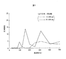
本願発明者らは、内燃エンジン(単気筒2ストロークエンジン)を搭載した手持ち式の刈払機の駆動源部つまりエンジン近傍に加速度センサを設置して、加速度センサの検出値つまり振動を計測した。その結果を図1〜図3に示す。このデータは、エンジンを覆うエンジンカバーに加速度センサ(検出軸が1軸)を設置した刈払機を使って、草刈りの作業と同じ操作、つまりハンドルを握って刈刃を左右に移動させながらエンジン回転数を増加させたときの計測データである。したがって、図1〜図3の計測データは実際に草刈り作業を行ったときの計測データではない。ここに刈払機に搭載された単気筒エンジンは、そのシリンダボアの軸線が上下方向に延びる状態で刈払機に組み付けられている。 The inventors of the present application installed an acceleration sensor in the vicinity of the driving source of a hand-held type brush cutter equipped with an internal combustion engine (single cylinder two-stroke engine), that is, in the vicinity of the engine, and measured the detection value of the acceleration sensor, that is, the vibration. The results are shown in FIGS. This data is the same operation as mowing using a brush cutter with an acceleration sensor (one detection axis) on the engine cover that covers the engine. In other words, the engine rotates while holding the handle and moving the cutting blade left and right. It is measurement data when the number is increased. Therefore, the measurement data in FIGS. 1 to 3 is not measurement data when the mowing operation is actually performed. Here, the single cylinder engine mounted on the brush cutter is assembled to the brush cutter in a state where the axis of the cylinder bore extends in the vertical direction.
図1は、検出軸を上下方向に向けた状態で加速度センサをエンジンカバーに取り付けて計測したデータであり、換言すれば上下振動のデータである。図2は、検出軸を前後方向に向けた状態で加速度センサをエンジンカバーに取り付けて計測したデータであり、換言すれば前後振動のデータである。図3は、検出軸を左右方向に向けた状態で加速度センサをエンジンカバーに取り付けて計測したデータであり、換言すれば左右振動のデータである。図1〜図3において、一点鎖線はエンジン回転数が8,500rpmの計測データであり、実線は10,000rpmの計測データである。 FIG. 1 shows data measured by attaching the acceleration sensor to the engine cover with the detection axis directed in the vertical direction, in other words, vertical vibration data. FIG. 2 shows data measured by attaching the acceleration sensor to the engine cover with the detection axis directed in the front-rear direction, in other words, data on front-rear vibration. FIG. 3 shows data measured by attaching the acceleration sensor to the engine cover with the detection axis directed in the left-right direction, in other words, left-right vibration data. 1 to 3, the alternate long and short dash line is measurement data at an engine speed of 8,500 rpm, and the solid line is measurement data at 10,000 rpm.
上記の「上下方向」、「前後方向」、「左右方向」を説明すると、「上下方向」とは、エンジンのシリンダボアの軸線方向つまり水平の台に刈払機を正規の姿勢で置いたときの垂直方向を意味する。「前後方向」とは、刈払機を操作する作業者から見て前後方向を意味し、概略的には、刈払機の操作チューブ(エンジンの動力を刈刃に伝達する動力伝達シャフト)の長手方向と言い換えることができる。「左右方向」とは、「左右」とは作業中の刈刃の移動方向を意味し、作業者から見て横方向と言い換えることができる。 The above "vertical direction", "front / rear direction", and "left / right direction" will be explained. The "vertical direction" means the vertical direction when the brush cutter is placed in a normal posture on the horizontal axis of the engine cylinder bore. Means direction. The “front-rear direction” means the front-rear direction as viewed from the operator who operates the brush cutter, and is roughly the longitudinal direction of the operation tube of the brush cutter (the power transmission shaft that transmits engine power to the cutting blade). In other words. “Left and right direction” means “moving direction of the cutting blade during work” and can be rephrased as the horizontal direction as viewed from the operator.
草刈り作業中のエンジン回転数は8,000〜10,000rpmであるが、この常用回転数領域において、上下振動の計測データを示す図1を参照すると、比較的大きな加速度が見られる。この上下振動は、実質的にエンジン振動であると考えることができる。したがって、内燃エンジンを搭載した作業機において、駆動源部に加速度センサを配設したときには、エンジン振動に由来する固有の加速度と、意図しない危険な状況に陥る可能性のある事態が発生したことで加速度センサが検出した加速度との区別が難しく、このことから、安全装置を作動させるための閾値を設定するのが事実上不可能であることが分かる。 Although the engine speed during mowing is 8,000 to 10,000 rpm, a relatively large acceleration can be seen in FIG. 1 showing measurement data of vertical vibration in this normal speed range. This vertical vibration can be considered to be engine vibration substantially. Therefore, in an operating machine equipped with an internal combustion engine, when an acceleration sensor is installed in the drive source, an inherent acceleration derived from engine vibrations and an unintended dangerous situation have occurred. It is difficult to distinguish from the acceleration detected by the acceleration sensor, and thus it is practically impossible to set a threshold value for operating the safety device.
すなわち、安全性の確保を重視して比較的小さな値の閾値を設定したときには、内燃エンジンを搭載した作業機の固有の振動に伴う加速度に対して安全装置が過敏に反応して強制的な作業停止を実行してしまうことになる。このことは、勿論、作業性を低下させてしまうことになるため、このような過敏な安全装置を備えた作業機は、例え安全性に優れていたとしてもユーザが購入を避けてしまう傾向になる。 In other words, when a relatively small threshold value is set with an emphasis on ensuring safety, the safety device reacts sensitively to the acceleration associated with the inherent vibration of the working machine equipped with the internal combustion engine, and the forced work The stop will be executed. Of course, this reduces workability. Therefore, a work machine equipped with such a sensitive safety device tends to avoid the purchase even if it is excellent in safety. Become.
図4〜図6は、駆動源として内燃エンジンを備えたチェーンソーに関するエンジン近傍の振動の計測データである。チェーンソーのエンジン近傍に上述した1軸式の加速度センサを設置して加速度センサの検出値つまり振動を計測した。 4 to 6 are measurement data of vibrations in the vicinity of the engine regarding a chainsaw provided with an internal combustion engine as a drive source. The above-described uniaxial acceleration sensor was installed in the vicinity of the chain saw engine, and the detection value of the acceleration sensor, that is, the vibration was measured.
図4〜図6に見られる「上下方向」、「前後方向」、「左右方向」は、基本的には刈払機と同じである。すなわち、「上下方向」とは、エンジンのシリンダボアの軸線方向つまり水平の台にチェーンソーを正規の姿勢で置いたときの垂直方向を意味する。「前後方向」とは、チェーンソーを操作する作業者から見て前後方向を意味する。また、「左右方向」は、チェーンソーを操作する作業者から見て横方向と言い換えることができる。 The “vertical direction”, “front / rear direction”, and “left / right direction” seen in FIGS. 4 to 6 are basically the same as those of the brush cutter. That is, the “vertical direction” means the axial direction of the cylinder bore of the engine, that is, the vertical direction when the chainsaw is placed in a normal posture on a horizontal base. The “front-rear direction” means the front-rear direction as viewed from the operator operating the chainsaw. Further, the “left-right direction” can be rephrased as the horizontal direction as viewed from the operator operating the chainsaw.
チェーンソーの作業中のエンジン回転数は8,000〜13,000rpmであるが、この常用回転数領域において、上下振動の計測データを示す図4を参照すると、比較的大きな加速度が見られる。この上下振動は実質的にエンジン振動であると考えることができる。 The engine speed during the operation of the chainsaw is 8,000 to 13,000 rpm. In this normal speed range, referring to FIG. 4 showing the measurement data of the vertical vibration, a relatively large acceleration can be seen. This vertical vibration can be considered to be engine vibration substantially.
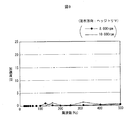
図7〜図9は、駆動源として内燃エンジンを備えたヘッジトリマに関するエンジン近傍の振動の計測データである。チェーンソーのエンジン近傍に上述した1軸式の加速度センサを設置して加速度センサの検出値つまり振動を計測した。 7 to 9 are measurement data of vibrations in the vicinity of the engine relating to a hedge trimmer having an internal combustion engine as a drive source. The above-described uniaxial acceleration sensor was installed in the vicinity of the chain saw engine, and the detection value of the acceleration sensor, that is, the vibration was measured.
図7〜図9に見られる「上下方向」、「前後方向」、「左右方向」は、基本的には刈払機やチェーンソーと同じである。すなわち、「上下方向」とは、エンジンのシリンダボアの軸線方向つまり水平の台にヘッジトリマを正規の姿勢で置いたときの垂直方向を意味する。「前後方向」とは、ヘッジトリマを操作する作業者から見て前後方向を意味する。また、「左右方向」は、ヘッジトリマを操作する作業者から見て横方向と言い換えることができる。なお、ヘッジトリマには、2ストローク内燃エンジンが横置きに搭載され、シリンダボアの軸線が前後方向に沿って延びているため、このヘッジトリマに関しては前後方向の振動にエンジン振動が含まれる。 The “vertical direction”, “front / rear direction”, and “left / right direction” seen in FIGS. 7 to 9 are basically the same as those of a brush cutter or a chainsaw. That is, the “vertical direction” means an axial direction of the cylinder bore of the engine, that is, a vertical direction when the hedge trimmer is placed in a normal posture on a horizontal base. The “front-rear direction” means the front-rear direction as viewed from the operator who operates the hedge trimmer. Further, the “left-right direction” can be rephrased as the horizontal direction as viewed from the operator operating the hedge trimmer. The hedge trimmer is mounted with a two-stroke internal combustion engine horizontally, and the axis of the cylinder bore extends in the front-rear direction. Therefore, the vibration in the front-rear direction includes engine vibration.
ヘッジトリマの作業中のエンジン回転数は8,000〜10,000rpmであるが、この常用回転数領域において、エンジン振動を含む前後振動の計測データを示す図8を参照すると、比較的大きな加速度が見られる。この上下振動は実質的にエンジン振動であると考えることができる。 The engine speed during the work of the hedge trimmer is 8,000 to 10,000 rpm. In this normal speed range, referring to FIG. 8 showing measurement data of longitudinal vibration including engine vibration, a relatively large acceleration is observed. This vertical vibration can be considered to be engine vibration substantially.
本発明の目的は、駆動源として内燃エンジンを搭載した作業機の駆動源部に加速度センサを設置したときに、エンジン振動による影響を抑えつつ、意図しない危険な状況に陥る可能性がある事態を的確に検出することのできる安全装置付き作業機を提供することにある。 An object of the present invention is to prevent a situation in which an unintended dangerous situation may occur while suppressing the influence of engine vibration when an acceleration sensor is installed in a drive source portion of a work machine equipped with an internal combustion engine as a drive source. An object of the present invention is to provide a work machine with a safety device that can be accurately detected.
上記の技術的課題は、本発明によれば、
駆動源部に内燃エンジンが搭載され、該内燃エンジンからの動力を刃物に伝達して該刃物を高速で動作させることにより作業を行っている最中に予期しない状況が発生したときに前記刃物から作業者を守る安全装置を備えた作業機を前提として、
前記駆動源部に取り付けられた加速度センサと、
該加速度センサからの出力を受けて、該加速度センサが検出した加速度が閾値よりも大きいときに、前記安全装置を作動させる安全信号を出力するコントローラとを有し、
前記加速度センサが、前記内燃エンジンのシリンダボアの軸線方向に対して該加速度センサの検出軸が傾斜した姿勢で前記駆動源部に取り付けられていることを特徴とする安全装置付き作業機を提供することにより達成される。
According to the present invention, the above technical problem is
An internal combustion engine is mounted on the drive source, and when an unexpected situation occurs during the operation by transmitting power from the internal combustion engine to the blade and operating the blade at a high speed, the blade Assuming a working machine with a safety device to protect workers,
An acceleration sensor attached to the drive source unit;
A controller that receives an output from the acceleration sensor and outputs a safety signal for operating the safety device when the acceleration detected by the acceleration sensor is greater than a threshold value;
To provide a work machine with a safety device, wherein the acceleration sensor is attached to the drive source unit in a posture in which a detection axis of the acceleration sensor is inclined with respect to an axial direction of a cylinder bore of the internal combustion engine. Is achieved.
すなわち、エンジンを備えた作業機には、典型的には、シリンダボアの軸線が上下方向に延びる姿勢でエンジンが組み付けられていることから、この典型的な作業機(刈払機やチェーンソー)で説明すれば、駆動源部に組み付けられた加速度センサは、その検出軸が上下方向に対して傾斜した状態で駆動源部に取り付けられる。この傾斜した加速度センサは、その本来有している感度が、駆動源部のエンジン振動である上下振動に対して鈍感になる。この感度低下の度合いは、検出軸の傾斜角度の大小によって規定することができる。なお、ヘッジトリマはエンジンが横置きにされ、シリンダボアの軸線が前後方向に延びている。このような横置きエンジンを備えた作業機であれば、シリンダボアの軸線に関して傾斜した状態で加速度センサを取り付ければよい。このことは、加速度センサが一軸式のセンサであっても、二軸式のセンサであっても、三軸式のセンサであっても同様であり、例えば二軸の検出軸を備えた加速度センサを採用したときには、そのいずれか一方の検出軸を上下方向に対して傾斜させればよく、その傾斜角度を調整することにより駆動源部の振動つまりエンジン振動に対して加速度センサの感度の低下度合いを調整することができる。これにより、エンジン振動の影響を低減することができることから、安全装置を作動させる閾値として比較的小さな値を設定することができる。 In other words, since a work machine equipped with an engine is typically assembled with an attitude in which the axis of the cylinder bore extends in the vertical direction, the typical work machine (a brush cutter or a chain saw) will be described. For example, the acceleration sensor assembled in the drive source unit is attached to the drive source unit with its detection axis inclined with respect to the vertical direction. The tilted acceleration sensor has an insensitive sensitivity to vertical vibration that is engine vibration of the drive source unit. The degree of sensitivity reduction can be defined by the inclination angle of the detection axis. In the hedge trimmer, the engine is placed horizontally, and the axis of the cylinder bore extends in the front-rear direction. If it is a working machine provided with such a horizontal engine, an acceleration sensor should just be attached in the state inclined with respect to the axis line of a cylinder bore. This is the same whether the acceleration sensor is a uniaxial sensor, a biaxial sensor, or a triaxial sensor. For example, an acceleration sensor having a biaxial detection axis. When either is used, it is only necessary to tilt one of the detection axes with respect to the vertical direction. By adjusting the tilt angle, the degree of decrease in the sensitivity of the acceleration sensor with respect to the vibration of the drive source, that is, the engine vibration Can be adjusted. Thereby, since the influence of engine vibration can be reduced, a relatively small value can be set as a threshold for operating the safety device.
加速度センサの検出軸が上下方向に対して傾斜していたとしても、キックバックや作業者の転倒などにより作業機が地面に落下したときの衝撃は大きいため、加速度センサが検出する加速度は大きい。また、キックバックに対して作業者が耐えられずに作業機を制御できない状態に陥ったときには、作業機の姿勢が大きく且つ急激に変化することになり、これに伴って駆動源部に設置した加速度センサの検出軸の方向も変化する。作業機が地面に落下したときも同様であり、この落下に伴って作業機の姿勢も変化するため、加速度センサはその本来有している感度に基づいて衝撃を検知する可能性が大きい。 Even if the detection axis of the acceleration sensor is inclined with respect to the vertical direction, the impact detected by the acceleration sensor is large because the impact is great when the work implement falls on the ground due to kickback or the operator's falling. Also, when the operator could not control the kickback due to the kickback, the attitude of the work implement would change greatly and suddenly, and it was installed in the drive source unit accordingly. The direction of the detection axis of the acceleration sensor also changes. The same is true when the work implement falls on the ground, and the posture of the work implement changes with the fall, and therefore the acceleration sensor has a high possibility of detecting an impact based on its inherent sensitivity.
上述したように、本発明によれば、比較的小さな値の閾値を設定しても、加速度センサをシリンダボアの軸線方向に対して傾斜させることに起因したエンジン振動に対する検知能力の低下によって、エンジン振動に関して閾値を高い値に設定したのと実質的に同じになる。したがって、比較的小さな値の閾値を設定したとしてもエンジン振動に対して安全装置が過敏に作動してしまうのを回避することができる。勿論、比較的低い閾値を設定することで、作業者の転倒などに伴って作業機が地面に落ちたときや、作業者が耐えきれないキックバックに対して的確に安全装置を作動させることができる。本発明によれば、また、安全装置の作動は加速度センサに依存しており、作業者の操作に依存していないことから、作業者は安全装置の作動に関して何らの意識を払う必要無しに作業することができる。 As described above, according to the present invention, even if a relatively small threshold value is set, the engine vibration is reduced due to a decrease in the detection capability for engine vibration caused by inclining the acceleration sensor with respect to the axial direction of the cylinder bore. This is substantially the same as setting the threshold value to a high value for. Therefore, even if a relatively small threshold value is set, it is possible to avoid the safety device from operating too sensitively to engine vibration. Of course, by setting a relatively low threshold value, the safety device can be actuated accurately when the work implement falls to the ground due to the operator's falling, or when the worker cannot withstand kickback. it can. According to the present invention, since the operation of the safety device depends on the acceleration sensor and does not depend on the operation of the worker, the worker can work without having to pay any attention to the operation of the safety device. can do.
駆動源部に傾斜して取り付けた加速度センサをどの程度までエンジン振動に対する感度を低下させるかは、作業機の特性を予め実験により求めて、加速度センサの取付傾斜角度つまりシリンダボアの軸線方向に対する検出軸の傾斜角度を調整することで対応することができる。勿論、ユーザが求める安全性は、作業環境によっても異なることから、ユーザが自らの手で加速度センサの傾斜角度を調整できるようにするのが好ましい。 The degree to which the sensitivity to the engine vibration is reduced by the inclination of the acceleration sensor mounted on the drive source is determined in advance by experimentally determining the characteristics of the work implement, and the detection axis for the acceleration sensor mounting tilt angle, that is, the cylinder bore axis direction. This can be dealt with by adjusting the inclination angle. Of course, since the safety required by the user varies depending on the work environment, it is preferable that the user can adjust the inclination angle of the acceleration sensor with his / her hand.
本発明の好ましい実施の形態では、前記加速度センサと、前記コントローラの一部を構成し且つ前記加速度センサが検出した加速度が閾値よりも大きいときに衝撃検知信号を生成する衝撃信号生成手段と、前記加速度センサが検出した瞬間的な衝撃の最大加速度を一定時間(例えば5秒間)保持し、この最大加速度が所定の閾値を越えているときには衝撃検知信号の出力を所定時間継続するタイマ手段とを備えた加速度センサユニットを有する。この加速度センサユニットを採用するときには、ユニットを作業機の駆動源部に取り付ける際に、加速度センサユニットをシリンダボアの軸線に対して傾斜して取り付けることで、当該ユニット内の加速度センサの検出軸を、シリンダボアの軸線方向である上下方向に対して傾斜させることができる。この種のセンサユニットは汎用品として入手可能であり、従って汎用品を使って作業機の安全装置を構築することでコストダウンを図ることができる。また、衝撃検知信号の出力を所定時間保持することで、安全装置の動作を確実に開始させることができる。 In a preferred embodiment of the present invention, the acceleration sensor, an impact signal generation unit that forms part of the controller and generates an impact detection signal when the acceleration detected by the acceleration sensor is greater than a threshold value, Timer means for holding a maximum acceleration of an instantaneous shock detected by the acceleration sensor for a predetermined time (for example, 5 seconds) and continuing the output of the impact detection signal for a predetermined time when the maximum acceleration exceeds a predetermined threshold. An acceleration sensor unit. When adopting this acceleration sensor unit, when the unit is attached to the drive source part of the work implement, the acceleration sensor unit is inclined with respect to the axis of the cylinder bore, so that the detection axis of the acceleration sensor in the unit is The cylinder bore can be inclined with respect to the vertical direction, which is the axial direction of the cylinder bore. This type of sensor unit is available as a general-purpose product. Therefore, it is possible to reduce the cost by constructing a safety device for a work machine using the general-purpose product. In addition, by holding the output of the impact detection signal for a predetermined time, the operation of the safety device can be started reliably.
この種の加速度センサユニットとして感度の異なる複数種類のユニットが販売されていることから、感度の異なる複数の加速度センサユニットをユーザに提示して、ユーザの作業環境に合致する感度の加速度センサユニットを選択することで、ユーザの作業環境に合致した安全装置を備えた作業機をユーザに提供することができる。本願発明は、内燃エンジンを駆動源とする刈払機に限らず、チェーンソー、ヘッジトリマなどの刃物を備えた作業機に好適に適用することができる。 Since multiple types of units with different sensitivities are sold as this type of acceleration sensor unit, a plurality of acceleration sensor units with different sensitivities are presented to the user, and an acceleration sensor unit with a sensitivity that matches the user's work environment is provided. By selecting, it is possible to provide the user with a work machine having a safety device that matches the user's work environment. The present invention can be suitably applied not only to a brush cutter using an internal combustion engine as a drive source, but also to a working machine equipped with a blade such as a chain saw or a hedge trimmer.
以下に、添付の図面に基づいて本発明の好ましい実施例を説明する。 Hereinafter, preferred embodiments of the present invention will be described with reference to the accompanying drawings.
図10、図11は実施例の肩掛けベルト式の刈払機つまり手持ち刈払機を示す図である。刈払機の斜視図である図10を参照して、刈払機100は、操作チューブ2の一端に配設された駆動源部4と、操作チューブ2の他端に配設された刈刃部6とを有し、操作チューブ2にはその長手方向中間部分にハンドル8が組み付けられている。この構成は、従来から周知の構成である。ハンドル6にはスロットルレバー10等が設けられ、作業者は、このスロットルレバー10を操作することで刈刃部6の動作速度を調整することができる。
10 and 11 are diagrams showing a shoulder belt type brush cutter, that is, a hand-held brush cutter according to an embodiment. Referring to FIG. 10, which is a perspective view of the brush cutter, the
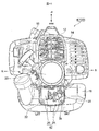
駆動源部4は、エンジンカバー12に包囲された単気筒の空冷2ストローク内燃エンジン14(図11)を有し、この単気筒エンジン14は、シリンダボアの軸線が上下方向に延びている。すなわち、単気筒2ストロークエンジン14は縦置きエンジンである。駆動源部4には、また、エンジン14の下方且つ隣接して配設された燃料タンク16を有し、この燃料タンク16から供給される燃料を受け取ってエンジン14の運転が実行される。図中、参照符号18は点火プラグを示し、点火プラグ18はエンジン14の頂部に取り付けられている。また、参照符号20はリコイルスタータを示す。リコイルスタータ20は、駆動源部4の後部において、後方に向けて突出する状態で取り付けられている。このリコイルスタータ20を操作することでエンジン14を始動することができる。リコイルスタータ20の下方且つ燃料タンク16の後方のデッドスペースには衝撃検出ボックス22が配設されている。
The
図11は、刈払機100を後端面つまり刈刃部6とは反対側から刈払機100を見た図であり、この図11では、衝撃検出ボックス22の蓋22aを取り外した状態で図示してある。衝撃検出ボックス22には、加速度センサユニット24と、マイコンからなるコントローラ26とが収容されている。
FIG. 11 is a view of the
加速度センサユニット24は圧電センサを含んでおり、この圧電センサのピックアップは、圧電セラミックを薄い円盤状の金属板に貼り付けた構成を有しており、その検出軸は単一である。この種のセンサユニットは、既に市販されており、ここでは、センサテック株式会社(本社:日本国京都府亀岡市大井町並河)が型式番号GLD又はSDSで製造販売するセンサユニットが採用されている。この加速度センサユニット24は、1kHz以下の周波数域で安定した出力特性を備えており、そして、このユニット24は、感度の相違によって複数種類のユニットが販売されている。勿論、市販の加速度センサユニット24を採用しないで、例えば半導体式センサのような加速度センサを刈払機100に組み付けるようにしてもよい。半導体式センサの典型例はピエゾ素子型、圧電素子型のセンサである。半導体式センサは、検出軸が単一の一軸式、2つの検出軸を備えた二軸式、3つの検出軸を備えた三軸式が知られている。本発明は一軸、二軸、三軸のいずれの加速度センサを採用することもできるが、一軸式の加速度センサを採用することで、コントローラ26での処理を簡素化することができるという利点がある。
The
この市販の加速度センサユニット24は、衝撃を検知するとその最大加速度を一定時間(例えば5秒間)保持し、この最大加速度が所定の閾値を越えているときには衝撃検知信号の出力を所定時間継続するマルチバイブレータ回路を備えている。すなわち、この加速度センサユニット24は単に加速度を検出するだけでなく、上述したコントローラ26の機能を一部有し、瞬間的な衝撃の最大加速度を一定時間保持して、この最大加速度が閾値を越えているときには衝撃検知信号を所定時間(例えば5秒間)継続して出力するタイマ機能を備えている。なお、加速度センサユニット24ではなくて、単なる加速度センサとコントローラ26との組み合わせで安全装置を構成したときには、このコントローラ26に上記のタイマ機能を組み込むのがよい。
The commercially available
加速度センサユニット24に含まれる加速度センサの単一の検出軸を図11に矢印DAで示してある。図12は、刈払機100を水平面に着座させた状態で、駆動源部4の背面に取り付けられた加速度センサユニット24の検出軸DAの傾斜状態を説明するための図である。
A single detection axis of the acceleration sensor included in the
図11を参照すると直ちに理解できるように、刈払機100を水平面に着座させたときに、加速度センサユニット24が上下方向Vに対して斜めの姿勢で取り付けられており、これにより検出軸DAが、図12にも示すように、シリンダボアの軸線方向である上下方向Vに対して傾斜している。図12の参照符号θ1は、上下方向Vに対する検出軸DAの傾斜角度である。なお、この図12の参照符号ASは、図11の加速度センサユニット24に含まれる加速度センサ(圧電センサ)を示す。
As can be readily understood with reference to FIG. 11, when the
加速度センサユニット24を上下方向に対して傾斜した状態で駆動源部4に搭載することにより、センサユニット24に含まれる加速度センサASの衝撃受け面は上下方向に対して傾斜して位置決めされることになる。図12において、加速度センサASの衝撃受け面の上下方向に対する傾斜角度をθ2で示してある。
By mounting the
図13は、加速度センサユニット24の検出軸DAの傾斜角度θ1とセンサユニット24の感度との関係を示す。この図13のデータは、刈払機100を地面に垂直落下させたときに、加速度センサユニット24が所定の出力値を出力するときの落下高さを計測したデータである。すなわち、刈払機100をどの高さ位置から落下させたときに、加速度センサユニット24が衝撃検知信号を出力するかを試験したときのデータが図13である。
FIG. 13 shows the relationship between the inclination angle θ1 of the detection axis DA of the
図13を参照して、加速度センサユニット24の取り付け角度を変えて刈払機100の落下方向つまり上下方向に対する検出軸DAの傾斜角度θ1を変更したときに、例えば、検出軸DAの傾斜角度θ1が45°のときは、約10cmの高さ位置から刈払機100を自由落下させたときに衝撃検知信号を出力している。これに対して、傾斜角度θ1が70°のときは、約30cmの高さ位置から刈払機100を自由落下させたときに衝撃検知信号を出力している。また、傾斜角度θ1が80°のときは、約90cmの高さ位置から刈払機100を自由落下させたときに衝撃検知信号を出力している。図13から、検出軸DAの傾斜角度θ1が大きくなるほど、加速度センサユニット24の感度が低下することが分かる。
Referring to FIG. 13, when the inclination angle θ1 of the detection axis DA with respect to the falling direction of the
図11に戻って、加速度センサユニット24の取付姿勢は、ビス28を弛めることより、実線で示す第1の傾斜位置から仮想線で示す第2の傾斜位置まで任意の傾斜角度に調整することができ、これにより検出軸DAの上下方向に対する傾斜角度θ1を変更することができる。勿論、ビス28を締める付けることで、加速度センサユニット24の傾斜した取付姿勢を固定することができる。なお、図示の例では、ビス28を中心にして、図11に実線で示す第1傾斜位置と、仮想線で示す第2傾斜位置の二つの異なる傾斜角度から一つの傾斜位置をユーザが選択する設計となっているが、3以上の傾斜位置から選択させるようにしてもよく、また、第1、第2の傾斜位置の間で無段階に加速度センサASの衝撃受け面の傾斜角度θ2を設定できるようにしてもよい。
Returning to FIG. 11, the mounting posture of the
加速度センサユニット24は所定値(閾値)以上の加速度を検出すると、上述したように、この加速度を検知したタイミングから所定時間(例えば5秒間)、衝撃検知信号をコントローラ26に供給し続ける。コントローラ26は、加速度センサユニット24から衝撃検知信号を受け取ると、図14に示すように、点火プラグ18に高電圧を供給する高電圧発生回路30に対して安全信号を供給し、所定時間供給し続けることになる。これにより高電圧発生回路30は高電圧を生成する機能が所定時間(例えば5秒間)停止される。点火プラグ18への高電圧の供給停止によりエンジン14は停止することになるが、その後直ちに点火プラグ18への高電圧供給が復活すると、エンジン14の慣性によってエンジン14が再起動してしまう可能性がある。したがって、この可能性が消失する時間が上記一定時間として例えば5秒が設定される。勿論、これよりも長い時間をタイマ設定してもよい。以上の安全制御により、加速度センサユニット24から衝撃検知信号を受け取ると直ちに高電圧発生回路30の一次コイルに対する電源供給が停止される。この電源供給停止が一定時間継続されることにより、エンジン14を完全に停止させることができる。そして、その結果、刈刃部6はその機能を停止し刈刃の回転が止まる。
When the
図15は、上述した刈払機100の基本構成図である。駆動源部4に配設されたエンジン14は、その出力が、操作チューブ2に挿入された動力伝達シャフト32を介して刈刃部6に供給される。駆動源部4には、エンジン14と動力伝達シャフト32との間に介装された遠心クラッチ34及び減衰ダンパ36が配設されている。また、刈刃部6にはベベルギア38が配設され、このベベルギア38を介して動力伝達シャフト32と円盤形の刈刃40とが連結されている。
FIG. 15 is a basic configuration diagram of the
上述したように、実施例の刈払機100によれば、加速度センサユニット24及びコントローラ26で構成される安全装置42によって、加速度センサユニット24が所定値以上の加速度を検知すると点火プラグ18に対する高電圧の供給が直ちに停止され、エンジン14が停止する。加速度センサユニット24の出力は所定時間(例えば5秒間)保持されるため、確実にエンジン14を停止させることができる。換言すれば、コントローラ26から出力される安全信号が比較的短い時間で終わってしまうと、安全信号がOFFした瞬間に、エンジン14に残留する慣性によってエンジン14が再起動してしまう虞がある。
As described above, according to the
また、加速度センサユニット24は、上下方向に対して、その検出軸DAが斜めに傾斜した状態で刈払機100に搭載されているため、図1を参照して前述したように刈払機100のエンジン14が動作することに伴う駆動源部4の上下振動つまりエンジン振動に対して、加速度センサユニット24が本来有している感度を低下させることができる。
Further, since the
加速度センサユニット24は、上述したように感度の相違によって複数種類のセンサユニットを入手することができることから、刈払機100のユーザに対して、その作業環境や刈払機100のエンジン振動特性に適した感度の加速度センサユニット24を例えば販売店で刈払機100に搭載することで、各ユーザに適した安全装置42を備えた刈り払い機100をユーザに提供することができる。持ち帰ったユーザは、実際に刈払機100を使用して、もう少し安全装置がエンジン振動に対して鈍感の方が良いのであれば、加速度センサユニット24が上下方向Vに対して起立した状態に近づく傾斜姿勢になる図3の仮想線で示す第2傾斜位置にセットし直すことで、このユーザの要望を満足させることができる。
Since the
加速度センサユニット24は、瞬間的な衝撃を受けたときに、その最大加速度が例えば5秒間保持され且つこの最大加速度が閾値よりも大きいときに衝撃検知信号が一定時間(例えば5秒間)継続して出力されるが、それ以降は加速度センサユニット24からの衝撃検知信号がOFF状態に復帰(コントローラ26からの安全信号の出力がOFF)するため、例えば安全装置42の作動(コントローラ26からの安全信号の出力)によってエンジン14が強制停止されたとしても、作業者が作業を再開したいときには、作業者は特別な操作無しに、リコイルスタータ20を操作してエンジン14を始動させることで作業を再開することができる。
When the
上記実施例では、加速度センサ(圧電センサ)ASを組み込んだ加速度センサユニット24を例に刈払機100の安全装置42を説明したが、このセンサユニット24を採用することなく安全装置42を構築することができる。すなわち、図12に図示のように検出軸DAが上下方向Vに対して傾斜した状態で加速度センサASを駆動源部4に取り付け、この加速度センサASの出力をコントローラ26に入力して(図16)、コントローラ26で予め設定した閾値と比較し、検出した加速度が閾値よりも大きいときに安全信号をコントローラ26から上述した高電圧発生回路30に供給して高電圧の生成を停止するようにしてもよい。また、このコントローラ26に前述したタイマ機能を付与して、所定時間、安全信号を出力し続けるようにしてもよい。なお、安全装置42のメモリに複数の値の異なる閾値を記憶しておき、ユーザ又は販売店が、この複数の閾値からユーザの作業環境などに適した閾値を選択することで、この選択した閾値をユーザ又は販売店で設定するようにしてもよい。
In the above embodiment, the
上述した実施例の刈払機100によれば、駆動源部4に取り付けた加速度センサユニット24が所定以上の衝撃を検知することでエンジン停止が実行されるため、意図しない危険な状況から作業者を保護することができるが、刈刃40の回転を停止させる機能停止手段つまり安全機構として何を制御対象にするかに関して、上記のエンジン停止に代えて又はエンジン停止と共に刈刃40の回転を強制停止するようにブレーキ機構を設けてもよい。
According to the
図17は、点火プラグを失火させることに加えて、遠心クラッチ34と減衰ダンパ36との間にブレーキ52が設けられ、このブレーキ52のアクチュエータ54に安全信号を供給して遠心クラッチ34の出力側を強制停止するようにした例を示す。なお、この図17の例では、高電圧発生回路30での高電圧生成を停止することで点火プラグ18への高電圧供給を停止させてエンジン停止させると共に上記のように遠心クラッチ34の出力側にブレーキ力を付与する構成が採用されているが、エンジン停止制御を省いてもよい。また、この図17の例では、コントローラ26が生成した安全信号を外部機器に供給する例を示す。外部機器とは例えば通信手段であり、コントローラ26から安全信号を受け取ると外部機器によって例えば作業者を雇用又は管理する作業又は業務管理会社や家族の携帯電話に通報が発信される。
In FIG. 17, in addition to misfire of the spark plug, a
図18は、制御対象に関する他の例を示す。この図18の例では、刈刃部6においてベベルギア38の直ぐ上流側にブレーキ60を設け、コントローラ26からの安全信号をブレーキ60のアクチュエータ62に入力してベベルギア38の直ぐ上流部に制動を加えるようにしてもよい。このベベルギア38の直ぐ下流に刈刃40が位置しているため、刈刃40の回転を直接的に強制停止することができる。この図16の例の変形例として、操作チューブ2の先端部にブレーキを設け、このブレーキで動力伝達シャフト32の先端部に制動力を加えるようにしてもよい。
FIG. 18 shows another example related to the controlled object. In the example of FIG. 18, the
加速度センサユニット24又は加速度センサASは駆動源部4の任意の箇所、例えばエンジンカバー12の内面や駆動源部4のデッドスペースに設置してもよいのは勿論である。
Needless to say, the
以上、添付の図面に基づいて本発明の実施例及びその変形例を説明したが、加速度センサユニット24又は加速度センサASを含む安全装置42は、駆動源として内燃エンジンを備えた他の作業機に対しても適用可能であるのは言うまでもない。具体的には、チェーンソー、ヘッジトリマであり、このような刃物を備えた作業機に本発明を適用することにより、エンジン振動による影響を低減することで比較的小さな閾値を設定することができる。これにより、作業者が意図しない危険な状況が発生する可能性のある事態を的確に判断することができ、これによりエンジン14や刃物の動作を停止する安全制御を実行することができる。
As mentioned above, although the Example of this invention and its modification were demonstrated based on attached drawing, the
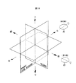
加速度センサASは、その衝撃受け面(ピックアップ面)と直交する軸が、加速度センサASの検出軸DAである。したがって、検出軸DAを上下方向に傾斜して配置するときに、加速度センサASの衝撃受け面の向きに関して自由度がある。図19は、加速度センサASの検出軸DAの上下方向に対して斜めに配置する場合に、加速度センサASの衝撃受け面の向きに関する自由度を説明するための図である。図19に書いてある「左右」「前後」「上下」について説明すると、「左右」は草刈り作業中に作業者によって操作される刈刃40の移動方向を意味している。「前後」は概略的には操作チューブ2の延び方向を意味している。「上下」とは、単一気筒の内燃エンジン14を搭載した刈払機100を例に説明すれば、内燃エンジン14のシリンダボアの軸線方向を意味している。
In the acceleration sensor AS, the axis orthogonal to the impact receiving surface (pickup surface) is the detection axis DA of the acceleration sensor AS. Therefore, when the detection axis DA is inclined in the vertical direction, there is a degree of freedom regarding the direction of the impact receiving surface of the acceleration sensor AS. FIG. 19 is a diagram for explaining the degree of freedom regarding the direction of the impact receiving surface of the acceleration sensor AS when it is arranged obliquely with respect to the vertical direction of the detection axis DA of the acceleration sensor AS. 19 will be described. “Left and right” means the moving direction of the
加速度センサASの衝撃受け面を水平面に置き、この加速度センサASの前後方向の軸線を中心に加速度センサASを回転させれば、加速度センサASの検出軸DAを上下方向に対して傾斜させることができる。この第1例では、加速度センサASは上下方向の加速度及び左右方向の加速度を検出することができる。他の例として、水平面に衝撃受け面を置いた加速度センサASの左右方向の軸線を中心に加速度センサASを回転させれば、加速度センサASの検出軸DAを上下方向に対して傾斜させることができる。この第2の例では、加速度センサASは上下方向の加速度及び前後方向の加速度を検出することができる。勿論、第1、第2の例を合体させれば、加速度センサASは左右方向、前後方向、上下方向の3方向の加速度を検出することができる。勿論、上記の第1、第2の例は、本発明に言う「検出軸DAを上下方向に対して傾斜させる」場合の典型例を説明しているに過ぎないのは言うまでもない。 If the impact receiving surface of the acceleration sensor AS is placed on a horizontal plane and the acceleration sensor AS is rotated about the longitudinal axis of the acceleration sensor AS, the detection axis DA of the acceleration sensor AS can be inclined with respect to the vertical direction. it can. In the first example, the acceleration sensor AS can detect vertical acceleration and horizontal acceleration. As another example, if the acceleration sensor AS is rotated about the horizontal axis of the acceleration sensor AS with the impact receiving surface placed on the horizontal plane, the detection axis DA of the acceleration sensor AS may be inclined with respect to the vertical direction. it can. In this second example, the acceleration sensor AS can detect vertical acceleration and longitudinal acceleration. Of course, if the first and second examples are combined, the acceleration sensor AS can detect accelerations in three directions, ie, the left-right direction, the front-rear direction, and the up-down direction. Of course, the first and second examples described above merely describe typical examples in the case of “inclining the detection axis DA with respect to the vertical direction” according to the present invention.
例えば、図6(チェーンソー:前後方向振動)を見ると、前後方向の振動でも比較的大きな加速度が見られる。この前後方向振動の影響及びエンジン振動の影響を抑えるのであれば、チェーンソーに関しては図19に図示の第2の例よりも第1の例つまり前後方向の軸線を中心に加速度センサASを回転させることで上下方向に対して検出軸DAを傾斜させる構成を採用すればよい。 For example, when looking at FIG. 6 (chain saw: longitudinal vibration), a relatively large acceleration can be seen even in the longitudinal vibration. If the influence of the longitudinal vibration and the influence of the engine vibration are to be suppressed, the acceleration sensor AS is rotated around the axis of the first example, that is, the longitudinal axis, with respect to the chain saw as compared with the second example shown in FIG. Thus, a configuration in which the detection axis DA is inclined with respect to the vertical direction may be employed.
仮に、上記第1、第2の例の何れであっても、刈払機100を使って作業するときには、作業者から見て刈刃40を斜め下に位置させる作業姿勢を取る。したがって、実施例のように駆動源部4の背面(第1鉛直面)に関して、例えば上記第1例の方法で加速度センサASを設置したとしても、実際の作業環境では、加速度センサASの衝撃受け面を三次元の3つの面の全てに対して傾斜して配置したのと同じ状態になり、前後方向、左右方向、上下方向の加速度を検出することができる。このことは、チェーンソーやヘッジトリマでも同じである。
Temporarily, even if it is any of the said 1st and 2nd example, when working using the
駆動源部4は相対的に重量が重いため、落下したときに真っ先に地面と衝突する確率が高く、また、キックバックが入力する刈刃40から最も遠くに位置しているため、駆動源部4に加速度センサユニット24又は加速度センサASを取り付けることにより、刈刃40が受ける衝撃を刈払機100の全長によって増幅して加速度センサASに入力できるという利点がある。この利点に加えて、駆動源部4に加速度センサユニット24又は加速度センサASを取り付けることにより、コントローラ26、高電圧発生部などを結線する配線が短くてもよいという利点がある。
Since the
100 刈払機
2 操作チューブ
4 駆動源部
6 刈刃部
8 ハンドル
12 エンジンカバー
14 エンジン
18 点火プラグ
20 リコイルスタータ
22 衝撃検出ボックス
24 加速度センサユニット
26 コントローラ
28 ビス(センサユニットの角度調整)
30 高電圧発生回路
32 動力伝達シャフト
34 遠心クラッチ
38 ベベルギア
40 刈刃
42 安全装置
DA 加速度センサの検出軸
AS 加速度センサ
DESCRIPTION OF
DESCRIPTION OF
Claims (6)
前記駆動源部に取り付けられた加速度センサと、
該加速度センサからの出力を受けて、該加速度センサが検出した加速度が閾値よりも大きいときに、前記安全装置を作動させる安全信号を出力するコントローラとを有し、
前記加速度センサが、前記内燃エンジンのシリンダボアの軸線方向に対して該加速度センサの検出軸が傾斜した姿勢で前記駆動源部に取り付けられていることを特徴とする安全装置付き作業機。 An internal combustion engine is mounted on the drive source, and when an unexpected situation occurs during the operation by transmitting power from the internal combustion engine to the blade and operating the blade at a high speed, the blade A work machine equipped with a safety device to protect the worker,
An acceleration sensor attached to the drive source unit;
A controller that receives an output from the acceleration sensor and outputs a safety signal for operating the safety device when the acceleration detected by the acceleration sensor is greater than a threshold value;
The work machine with a safety device, wherein the acceleration sensor is attached to the drive source unit in a posture in which a detection axis of the acceleration sensor is inclined with respect to an axial direction of a cylinder bore of the internal combustion engine.
前記コントローラは、前記加速度センサユニットからの衝撃検知信号を受けて前記安全信号を出力する、請求項1又は2に記載の安全装置付き作業機。 The acceleration sensor, an impact signal generating unit that forms part of the controller and generates an impact detection signal when the acceleration detected by the acceleration sensor is greater than a threshold value, and an output that holds the impact detection signal for a predetermined time An acceleration sensor unit having holding means,
The work machine with a safety device according to claim 1, wherein the controller receives the impact detection signal from the acceleration sensor unit and outputs the safety signal.
Priority Applications (3)
| Application Number | Priority Date | Filing Date | Title |
|---|---|---|---|
| JP2009123599A JP5448568B2 (en) | 2009-05-21 | 2009-05-21 | Work machine with safety device |
| US12/783,886 US9769984B2 (en) | 2009-05-21 | 2010-05-20 | Work apparatus with safety equipment |
| EP10163544A EP2253190A1 (en) | 2009-05-21 | 2010-05-21 | Work apparatus with safety equipment |
Applications Claiming Priority (1)
| Application Number | Priority Date | Filing Date | Title |
|---|---|---|---|
| JP2009123599A JP5448568B2 (en) | 2009-05-21 | 2009-05-21 | Work machine with safety device |
Publications (3)
| Publication Number | Publication Date |
|---|---|
| JP2010268731A JP2010268731A (en) | 2010-12-02 |
| JP2010268731A5 JP2010268731A5 (en) | 2012-05-17 |
| JP5448568B2 true JP5448568B2 (en) | 2014-03-19 |
Family
ID=42470781
Family Applications (1)
| Application Number | Title | Priority Date | Filing Date |
|---|---|---|---|
| JP2009123599A Active JP5448568B2 (en) | 2009-05-21 | 2009-05-21 | Work machine with safety device |
Country Status (3)
| Country | Link |
|---|---|
| US (1) | US9769984B2 (en) |
| EP (1) | EP2253190A1 (en) |
| JP (1) | JP5448568B2 (en) |
Families Citing this family (6)
| Publication number | Priority date | Publication date | Assignee | Title |
|---|---|---|---|---|
| JP6464357B2 (en) * | 2014-10-11 | 2019-02-06 | 株式会社ドリーム・ワークス | Chain saw, chain saw work evaluation system, and chain saw work evaluation method |
| EP3031315B1 (en) * | 2014-12-09 | 2021-09-01 | Robert Bosch GmbH | Garden device handle device |
| JP6683056B2 (en) * | 2016-07-29 | 2020-04-15 | 工機ホールディングス株式会社 | Self-propelled work machine |
| JP2018082682A (en) * | 2016-11-25 | 2018-05-31 | 本田技研工業株式会社 | Working machine |
| JP6982167B2 (en) * | 2018-03-09 | 2021-12-17 | 本田技研工業株式会社 | Working machine |
| CN115509177B (en) * | 2022-09-22 | 2024-01-12 | 成都飞机工业(集团)有限责任公司 | Method, device, equipment and medium for monitoring abnormality in part machining process |
Family Cites Families (28)
| Publication number | Priority date | Publication date | Assignee | Title |
|---|---|---|---|---|
| US2748810A (en) * | 1955-02-21 | 1956-06-05 | Leonard M Strunk | Chain saw guide bar with lubricating means |
| US3353525A (en) * | 1965-09-07 | 1967-11-21 | Tillotson Mfg Co | Fuel feed system and throttle control for internal combustion engines |
| US3606745A (en) * | 1969-09-08 | 1971-09-21 | Massey Ferguson Ind Ltd | Grain flow rate monitor |
| JPS4845873A (en) | 1971-10-12 | 1973-06-30 | ||
| US3923126A (en) * | 1974-06-25 | 1975-12-02 | Textron Inc | Band type brake for a chain saw |
| US4178741A (en) * | 1978-08-17 | 1979-12-18 | The Toro Company | Safety system for riding mower |
| US4553326A (en) * | 1983-01-14 | 1985-11-19 | Mcculloch Corporation | Chain saw braking system |
| JPS62198320A (en) | 1986-02-25 | 1987-09-02 | 松下電工株式会社 | Reaper |
| JPH031221Y2 (en) * | 1986-05-02 | 1991-01-16 | ||
| JPH02131822A (en) | 1988-11-11 | 1990-05-21 | Matsushita Electric Ind Co Ltd | Minute hole press machining device |
| JPH02131822U (en) | 1989-04-03 | 1990-11-01 | ||
| JPH0312477U (en) | 1989-06-23 | 1991-02-07 | ||
| JP3038492B2 (en) | 1990-10-24 | 2000-05-08 | 惣一 明井 | Method and device for stopping mower |
| JPH08118960A (en) | 1994-10-24 | 1996-05-14 | Nishikawa Rubber Co Ltd | Center pillar weather strip |
| JP3576620B2 (en) | 1995-01-12 | 2004-10-13 | 株式会社共立 | Emergency braking device |
| SE508267C2 (en) * | 1996-04-04 | 1998-09-21 | Electrolux Ab | Drive unit for a handheld work tool |
| DE19857061C2 (en) * | 1998-12-10 | 2000-11-02 | Hilti Ag | Method and device for avoiding accidents in hand-held machine tools due to tool blocking |
| JP2002311047A (en) | 2001-04-10 | 2002-10-23 | Aisin Seiki Co Ltd | Acceleration detecting device |
| JP2003090846A (en) | 2001-09-19 | 2003-03-28 | Mitsubishi Electric Corp | Acceleration detection device |
| US20040181951A1 (en) * | 2003-03-17 | 2004-09-23 | Wittke Edward R. | Chain saw safety system |
| JP2006172984A (en) | 2004-12-17 | 2006-06-29 | Ubukata Industries Co Ltd | Fall sensor |
| JP4491320B2 (en) * | 2004-10-15 | 2010-06-30 | 富士重工業株式会社 | Brush cutter |
| JP4754859B2 (en) | 2005-04-12 | 2011-08-24 | 株式会社ニッカリ | Mower and electric mower |
| JP2008118960A (en) | 2006-11-15 | 2008-05-29 | Husqvarna Zenoah Co Ltd | Bush cutter |
| US20100064532A1 (en) * | 2007-07-31 | 2010-03-18 | Edward Raymond Wittke | Chain saw 3D relative positional monitoring and anti-kickback actuation system |
| US8752301B2 (en) * | 2009-04-08 | 2014-06-17 | Rex George | Chainsaw incorporating a safety device system |
| JP5448567B2 (en) * | 2009-05-21 | 2014-03-19 | 株式会社やまびこ | Work machine with safety device |
| JP5448569B2 (en) * | 2009-05-21 | 2014-03-19 | 株式会社やまびこ | Brush cutter with safety device |
-
2009
- 2009-05-21 JP JP2009123599A patent/JP5448568B2/en active Active
-
2010
- 2010-05-20 US US12/783,886 patent/US9769984B2/en active Active
- 2010-05-21 EP EP10163544A patent/EP2253190A1/en not_active Withdrawn
Also Published As
| Publication number | Publication date |
|---|---|
| US9769984B2 (en) | 2017-09-26 |
| JP2010268731A (en) | 2010-12-02 |
| US20100294616A1 (en) | 2010-11-25 |
| EP2253190A1 (en) | 2010-11-24 |
Similar Documents
| Publication | Publication Date | Title |
|---|---|---|
| JP5448569B2 (en) | Brush cutter with safety device | |
| JP5448567B2 (en) | Work machine with safety device | |
| JP5448568B2 (en) | Work machine with safety device | |
| AU2009286589B2 (en) | Safety device for portable tools with a heat engine, capable of stopping the operation thereof after sudden, violent movements | |
| AU2011289336B2 (en) | Kickback detection method and apparatus | |
| FI72444B (en) | SAEKERHETSSYSTEM I ETT HANDSTYRT, MOTORDRIVET HANDVERKTYG. | |
| JP6778575B2 (en) | Work machine | |
| US20100064532A1 (en) | Chain saw 3D relative positional monitoring and anti-kickback actuation system | |
| JP6981803B2 (en) | Strike tool | |
| JP2015008693A (en) | Engine work machine | |
| JP5739676B2 (en) | Brake device for portable work machine with centrifugal clutch | |
| EP3237739B1 (en) | Internal combustion engine and method for safe starting the same | |
| CN110520614B (en) | Internal combustion engine | |
| US9357702B2 (en) | Engine-powered work tool provided with stand | |
| JP2022115292A (en) | Cutting blade protection device, bush cutter and bush cutting method | |
| WO2021038859A1 (en) | Rotary machining tool and rotary machining system | |
| JP2022544139A (en) | Tool detection in handheld power tools | |
| JP2021016329A (en) | Work machine | |
| JPH10229721A (en) | Cutter for mower |
Legal Events
| Date | Code | Title | Description |
|---|---|---|---|
| A521 | Request for written amendment filed |
Free format text: JAPANESE INTERMEDIATE CODE: A523 Effective date: 20120326 |
|
| A621 | Written request for application examination |
Free format text: JAPANESE INTERMEDIATE CODE: A621 Effective date: 20120326 |
|
| A977 | Report on retrieval |
Free format text: JAPANESE INTERMEDIATE CODE: A971007 Effective date: 20121228 |
|
| TRDD | Decision of grant or rejection written | ||
| A01 | Written decision to grant a patent or to grant a registration (utility model) |
Free format text: JAPANESE INTERMEDIATE CODE: A01 Effective date: 20131205 |
|
| A61 | First payment of annual fees (during grant procedure) |
Free format text: JAPANESE INTERMEDIATE CODE: A61 Effective date: 20131224 |
|
| R150 | Certificate of patent or registration of utility model |
Ref document number: 5448568 Country of ref document: JP Free format text: JAPANESE INTERMEDIATE CODE: R150 Free format text: JAPANESE INTERMEDIATE CODE: R150 |
|
| R250 | Receipt of annual fees |
Free format text: JAPANESE INTERMEDIATE CODE: R250 |
|
| R250 | Receipt of annual fees |
Free format text: JAPANESE INTERMEDIATE CODE: R250 |
|
| R250 | Receipt of annual fees |
Free format text: JAPANESE INTERMEDIATE CODE: R250 |
|
| R250 | Receipt of annual fees |
Free format text: JAPANESE INTERMEDIATE CODE: R250 |
|
| R250 | Receipt of annual fees |
Free format text: JAPANESE INTERMEDIATE CODE: R250 |
|
| R250 | Receipt of annual fees |
Free format text: JAPANESE INTERMEDIATE CODE: R250 |
|
| R250 | Receipt of annual fees |
Free format text: JAPANESE INTERMEDIATE CODE: R250 |