JP5448300B2 - Cemented carbide tool for mining and construction, and manufacturing method thereof - Google Patents
Cemented carbide tool for mining and construction, and manufacturing method thereof Download PDFInfo
- Publication number
- JP5448300B2 JP5448300B2 JP2006545279A JP2006545279A JP5448300B2 JP 5448300 B2 JP5448300 B2 JP 5448300B2 JP 2006545279 A JP2006545279 A JP 2006545279A JP 2006545279 A JP2006545279 A JP 2006545279A JP 5448300 B2 JP5448300 B2 JP 5448300B2
- Authority
- JP
- Japan
- Prior art keywords
- cemented carbide
- content
- surface portion
- tool body
- carbide tool
- Prior art date
- Legal status (The legal status is an assumption and is not a legal conclusion. Google has not performed a legal analysis and makes no representation as to the accuracy of the status listed.)
- Active
Links
- 238000004519 manufacturing process Methods 0.000 title claims description 6
- 238000005065 mining Methods 0.000 title claims description 5
- 238000010276 construction Methods 0.000 title 1
- 239000011651 chromium Substances 0.000 claims description 29
- 239000002245 particle Substances 0.000 claims description 20
- 238000005245 sintering Methods 0.000 claims description 16
- 239000011230 binding agent Substances 0.000 claims description 15
- 239000000843 powder Substances 0.000 claims description 15
- 229910052804 chromium Inorganic materials 0.000 claims description 11
- 238000000034 method Methods 0.000 claims description 6
- 239000010419 fine particle Substances 0.000 claims description 5
- 102000003712 Complement factor B Human genes 0.000 claims description 3
- 108090000056 Complement factor B Proteins 0.000 claims description 3
- UFGZSIPAQKLCGR-UHFFFAOYSA-N chromium carbide Chemical compound [Cr]#C[Cr]C#[Cr] UFGZSIPAQKLCGR-UHFFFAOYSA-N 0.000 claims description 3
- 239000011362 coarse particle Substances 0.000 claims description 3
- 229910003470 tongbaite Inorganic materials 0.000 claims description 3
- 239000000470 constituent Substances 0.000 claims 2
- 230000003796 beauty Effects 0.000 claims 1
- 238000000465 moulding Methods 0.000 claims 1
- 239000010941 cobalt Substances 0.000 description 13
- 229910017052 cobalt Inorganic materials 0.000 description 13
- GUTLYIVDDKVIGB-UHFFFAOYSA-N cobalt atom Chemical compound [Co] GUTLYIVDDKVIGB-UHFFFAOYSA-N 0.000 description 13
- 239000000203 mixture Substances 0.000 description 7
- 238000000445 field-emission scanning electron microscopy Methods 0.000 description 6
- OKTJSMMVPCPJKN-UHFFFAOYSA-N Carbon Chemical compound [C] OKTJSMMVPCPJKN-UHFFFAOYSA-N 0.000 description 5
- VYZAMTAEIAYCRO-UHFFFAOYSA-N Chromium Chemical compound [Cr] VYZAMTAEIAYCRO-UHFFFAOYSA-N 0.000 description 5
- 229910052799 carbon Inorganic materials 0.000 description 4
- 150000001247 metal acetylides Chemical class 0.000 description 4
- UONOETXJSWQNOL-UHFFFAOYSA-N tungsten carbide Chemical compound [W+]#[C-] UONOETXJSWQNOL-UHFFFAOYSA-N 0.000 description 4
- 238000005520 cutting process Methods 0.000 description 3
- 230000007423 decrease Effects 0.000 description 3
- 238000000227 grinding Methods 0.000 description 3
- IJGRMHOSHXDMSA-UHFFFAOYSA-N Atomic nitrogen Chemical compound N#N IJGRMHOSHXDMSA-UHFFFAOYSA-N 0.000 description 2
- 238000004458 analytical method Methods 0.000 description 2
- 238000005553 drilling Methods 0.000 description 2
- 239000007789 gas Substances 0.000 description 2
- 229910052500 inorganic mineral Inorganic materials 0.000 description 2
- 239000011707 mineral Substances 0.000 description 2
- 239000011435 rock Substances 0.000 description 2
- 229910009043 WC-Co Inorganic materials 0.000 description 1
- CKUAXEQHGKSLHN-UHFFFAOYSA-N [C].[N] Chemical compound [C].[N] CKUAXEQHGKSLHN-UHFFFAOYSA-N 0.000 description 1
- 239000000956 alloy Substances 0.000 description 1
- 229910045601 alloy Inorganic materials 0.000 description 1
- 239000010426 asphalt Substances 0.000 description 1
- 150000001844 chromium Chemical class 0.000 description 1
- 230000000295 complement effect Effects 0.000 description 1
- 239000002131 composite material Substances 0.000 description 1
- 150000001875 compounds Chemical class 0.000 description 1
- 239000004567 concrete Substances 0.000 description 1
- 238000010586 diagram Methods 0.000 description 1
- 238000007598 dipping method Methods 0.000 description 1
- 238000009472 formulation Methods 0.000 description 1
- 239000010439 graphite Substances 0.000 description 1
- 229910002804 graphite Inorganic materials 0.000 description 1
- 238000010438 heat treatment Methods 0.000 description 1
- 239000000463 material Substances 0.000 description 1
- 238000010297 mechanical methods and process Methods 0.000 description 1
- 238000005555 metalworking Methods 0.000 description 1
- 229910052757 nitrogen Inorganic materials 0.000 description 1
- 238000010422 painting Methods 0.000 description 1
- 230000002093 peripheral effect Effects 0.000 description 1
- 230000008092 positive effect Effects 0.000 description 1
- 239000002994 raw material Substances 0.000 description 1
- 239000007787 solid Substances 0.000 description 1
- 238000005507 spraying Methods 0.000 description 1
Images


Classifications
-
- C—CHEMISTRY; METALLURGY
- C22—METALLURGY; FERROUS OR NON-FERROUS ALLOYS; TREATMENT OF ALLOYS OR NON-FERROUS METALS
- C22C—ALLOYS
- C22C1/00—Making non-ferrous alloys
- C22C1/04—Making non-ferrous alloys by powder metallurgy
- C22C1/05—Mixtures of metal powder with non-metallic powder
- C22C1/051—Making hard metals based on borides, carbides, nitrides, oxides or silicides; Preparation of the powder mixture used as the starting material therefor
-
- B—PERFORMING OPERATIONS; TRANSPORTING
- B32—LAYERED PRODUCTS
- B32B—LAYERED PRODUCTS, i.e. PRODUCTS BUILT-UP OF STRATA OF FLAT OR NON-FLAT, e.g. CELLULAR OR HONEYCOMB, FORM
- B32B29/00—Layered products comprising a layer of paper or cardboard
-
- B—PERFORMING OPERATIONS; TRANSPORTING
- B22—CASTING; POWDER METALLURGY
- B22F—WORKING METALLIC POWDER; MANUFACTURE OF ARTICLES FROM METALLIC POWDER; MAKING METALLIC POWDER; APPARATUS OR DEVICES SPECIALLY ADAPTED FOR METALLIC POWDER
- B22F7/00—Manufacture of composite layers, workpieces, or articles, comprising metallic powder, by sintering the powder, with or without compacting wherein at least one part is obtained by sintering or compression
- B22F7/06—Manufacture of composite layers, workpieces, or articles, comprising metallic powder, by sintering the powder, with or without compacting wherein at least one part is obtained by sintering or compression of composite workpieces or articles from parts, e.g. to form tipped tools
-
- C—CHEMISTRY; METALLURGY
- C22—METALLURGY; FERROUS OR NON-FERROUS ALLOYS; TREATMENT OF ALLOYS OR NON-FERROUS METALS
- C22C—ALLOYS
- C22C29/00—Alloys based on carbides, oxides, nitrides, borides, or silicides, e.g. cermets, or other metal compounds, e.g. oxynitrides, sulfides
- C22C29/02—Alloys based on carbides, oxides, nitrides, borides, or silicides, e.g. cermets, or other metal compounds, e.g. oxynitrides, sulfides based on carbides or carbonitrides
- C22C29/06—Alloys based on carbides, oxides, nitrides, borides, or silicides, e.g. cermets, or other metal compounds, e.g. oxynitrides, sulfides based on carbides or carbonitrides based on carbides, but not containing other metal compounds
- C22C29/08—Alloys based on carbides, oxides, nitrides, borides, or silicides, e.g. cermets, or other metal compounds, e.g. oxynitrides, sulfides based on carbides or carbonitrides based on carbides, but not containing other metal compounds based on tungsten carbide
-
- B—PERFORMING OPERATIONS; TRANSPORTING
- B22—CASTING; POWDER METALLURGY
- B22F—WORKING METALLIC POWDER; MANUFACTURE OF ARTICLES FROM METALLIC POWDER; MAKING METALLIC POWDER; APPARATUS OR DEVICES SPECIALLY ADAPTED FOR METALLIC POWDER
- B22F2999/00—Aspects linked to processes or compositions used in powder metallurgy
-
- Y—GENERAL TAGGING OF NEW TECHNOLOGICAL DEVELOPMENTS; GENERAL TAGGING OF CROSS-SECTIONAL TECHNOLOGIES SPANNING OVER SEVERAL SECTIONS OF THE IPC; TECHNICAL SUBJECTS COVERED BY FORMER USPC CROSS-REFERENCE ART COLLECTIONS [XRACs] AND DIGESTS
- Y10—TECHNICAL SUBJECTS COVERED BY FORMER USPC
- Y10T—TECHNICAL SUBJECTS COVERED BY FORMER US CLASSIFICATION
- Y10T428/00—Stock material or miscellaneous articles
- Y10T428/12—All metal or with adjacent metals
- Y10T428/12014—All metal or with adjacent metals having metal particles
- Y10T428/12021—All metal or with adjacent metals having metal particles having composition or density gradient or differential porosity
Description
本発明は、岩石と鉱物の穿孔及び切削用の工具に望ましく使用される超硬合金ボディに関連する。また、アスファルト及びコンクリート用に使用される超硬合金工具も、含まれる。さらに、具体的には本発明は、補足的な性質を有する二つの異なる微細組織区域が存在する焼結技術を介して作られた超硬合金に関する。 The present invention relates to a cemented carbide body desirably used in tools for drilling and cutting rocks and minerals. Also included are cemented carbide tools used for asphalt and concrete. More specifically, the present invention relates to a cemented carbide made via a sintering technique in which there are two different microstructured areas with complementary properties.
超硬合金、その粒径、並びにバインダー相(例えば、コバルト)は、各々が複合材料の性能に影響を及ぼす。例えば、炭化タングステンの小さくて/微細な粒径が、多くの耐摩耗性材料をもたらす。コバルト含有量の増加が、一般的に靭性の増加を導く。 The cemented carbide, its particle size, and the binder phase (eg, cobalt) each affect the performance of the composite material. For example, the small / fine particle size of tungsten carbide results in many wear resistant materials. Increasing cobalt content generally leads to increased toughness.
微細粒径を備える超硬合金は、初期粉末混合物中に粒精製剤の取込によって製造される。このような超硬合金は、この顕微鏡組織全体が微細な粒径を備える。WC−Co超硬合金のような超硬合金の傾向は、焼結の際に粗くなるWC粒に対してであるので、粗い粒径を有する超硬合金は、いずれの粒精製剤を取り込むこと無しで製造される。このような超硬合金は、この顕微鏡組織全体が粗い粒径を有する。評価することができるように、これらの硬質ボディは、超硬合金ボディ全体が均一顕微鏡組織を有する。 A cemented carbide with a fine grain size is produced by incorporating a grain refiner into the initial powder mixture. In such a cemented carbide, the entire microstructure has a fine particle size. Since the tendency of cemented carbides such as WC-Co cemented carbides is to WC grains that become coarse during sintering, cemented carbides with coarse grain sizes will incorporate any grain refiner. Manufactured without. In such a cemented carbide, the entire microstructure has a coarse particle size. As can be appreciated, these hard bodies have a uniform microstructure throughout the cemented carbide body.
少なくとも二つの異なる顕微鏡組織を有する超硬合金ボディが公知である。例えば、頑丈な超硬合金品質等級のコアを有し、且つ多くの耐摩耗性品質等級のカバーを有するドリルが、ヨーロッパ特許A951576号に開示される。 Cemented carbide bodies having at least two different microstructures are known. For example, a drill having a solid cemented carbide quality grade core and a number of wear quality grade covers is disclosed in European Patent A951576.
ヨーロッパ特許A194018号は、粗い粒状のタングステン炭化物粒子を有する中央の層と、微細な粒状のタングステン炭化物粒子を有する周辺の層と、から形成された線引きダイスに関する。最初に、これらの層は、同一含有量のコバルトを有する。焼結後に中央の粗い粒状の層は、コバルト含有量が減少する。 European Patent A194018 relates to a drawing die formed from a central layer having coarse granular tungsten carbide particles and a peripheral layer having fine granular tungsten carbide particles. Initially, these layers have the same content of cobalt. The coarse granular layer in the center after sintering has a reduced cobalt content.
ヨーロッパ特許A257869号は、耐摩耗性の頂部と強靭なコアとを有するロックビットボタンを開示する。この頂部は、低コバルト含有量で微細なWC粒径を有する粉末から作られ、且つこのコア部分は、高Co含有量で粗いWC粒を有する粉末から作られる。焼結後、二つの部分においてCo含有量について何も開示しない。しかしながら、この場合においても、粗い粒状の部分におけるCo含有量は、微細な粒状の層において費用の点で減少されるであろう。同様の開示が米国特許4,359,335号に見られる。 European Patent A257869 discloses a lock bit button having a wear-resistant top and a tough core. The top is made from a powder with a low cobalt content and fine WC particle size, and the core is made from a powder with high Co content and coarse WC grains. After sintering, nothing is disclosed about the Co content in the two parts. However, even in this case, the Co content in the coarse granular part will be reduced in cost in the fine granular layer. Similar disclosure is found in US Pat. No. 4,359,335.
代わりの到達方法が米国特許4,743,515号に開示され、好ましくは岩石穿孔加工及び鉱物切削加工用の超硬合金ボディを開示する。このボディは、η相の無い超硬合金の表面領域によって取り囲まれたη相を含み、且つ表面に低含有量のコバルトとη相領域近くに高含有量のコバルトと、を有する超硬合金コアからなる。米国特許4,843,039号は同様であるが、金属加工用の切削工具インサートに関する。 An alternative approach is disclosed in US Pat. No. 4,743,515, which preferably discloses a cemented carbide body for rock drilling and mineral cutting. The body includes a η phase surrounded by a surface region of a cemented carbide having no η phase , and having a low content of cobalt on the surface and a high content of cobalt near the η phase region. Consists of. US Pat. No. 4,843,039 is similar but relates to a cutting tool insert for metalworking.
米国特許5,623,723号は、耐摩耗性領域を有する超硬合金ボディを製造する方法に関する。この方法は、次の工程を、超硬合金の成形体を備える工程、前記成形体の露出表面の少なくとも一部分に粒精製剤の粉末を配置する工程、及びグリーン成形体の中心に向かって粒精製剤を拡散するように前記成形体及び粒精製剤粉末を熱処理することによって、露出面から内側に向かって粒精製剤が配置された表面領域を形成して、且つ内側領域を形成する工程、を含む。結果として、超硬合金ボディは、小さいが粒径であるがボディの内側部分のCo含有量が多いCo含有量を有する粒径を有する表面領域が得られる。このことは、結果として小さなWC粒径として得られた増加した耐摩耗性がCo含有量の増加によって失われる所定の広さになること意味する。 U.S. Pat. No. 5,623,723 relates to a method of manufacturing a cemented carbide body having a wear resistant region. This method includes the following steps: a step of providing a cemented carbide molded body, a step of disposing a powder of a grain refiner on at least a part of the exposed surface of the molded body, and a grain refinement toward the center of the green molded body. Forming a surface region in which the grain refiner is disposed from the exposed surface to the inside by forming a heat treatment of the molded body and the grain refiner powder so as to diffuse the formulation, and forming an inner region; Including. As a result, the cemented carbide body has a surface region with a particle size that is small but has a particle size but a high Co content in the inner portion of the body. This means that the increased wear resistance obtained as a result of the small WC particle size results in a predetermined area that is lost with increasing Co content.
したがって、低バインダー相の含有量と微細なWC粒径を有する表面領域とすなわち大きな耐摩耗性を備える超硬合金、及びそれを製造する方法を提供することを、本発明の目的とする。 Accordingly, it is an object of the present invention to provide a cemented carbide having a low binder phase content and a surface region having a fine WC grain size, that is, a high wear resistance, and a method for producing the same.
さらに、表面部分に圧縮応力を備える、このインサート/ボタンの強度と靭性にプラスの効果を有する超硬合金インサート/ボタンを提供することを、本発明の目的とする。 Furthermore, it is an object of the present invention to provide a cemented carbide insert / button having a positive effect on the strength and toughness of the insert / button having a compressive stress in the surface portion.
内側部分の粒径とコバルト含有量より小さな粒径と低いコバルト含有量を有する表面領域を供える超硬合金ボディを得るために、単一のタングステン炭化物とバインダーから形成することが可能であることが、驚くべきことが判明した。 It can be formed from a single tungsten carbide and binder to obtain a cemented carbide body that has a surface area with a particle size smaller than the inner portion particle size and cobalt content and a lower cobalt content. , Turned out to be amazing.
本発明に従い、少なくとも一つの表面部分を含む採鉱及び建築に適用の超硬合金工具インサート/ボタンが提供され、バインダーの乏しい表面区域は、超硬合金ボディの直径/幅の0.05〜0.9好ましくは0.1〜0.5最も好ましくは0.15〜0.4の幅を有し、且つ粒径は内側部分より小さくて、且つCo含有量は焼結後の表面で圧縮応力を生じる前記内側部分の含有量より少ない。さらに具体的には、表面部分でのCo含有量は、内側部分のCo含有量の<1好ましくは<0.9最も好ましくは<0.75であり、且つこの表面区域のWC粒径は、内側部分のWCの粒径の<1好ましくは<0.9最も好ましくは<0.8である。好ましくは、表面領域は、表面部分の因子A((wt%Cr/wt%バインダー相)+0.01)及びボディ部分で採取した因子B((wt%Cr/wt%バインダー相)+0.01)との間の比率が、最も少ないCr含有量によって特徴つけられ、且つA/B>1.5好ましくはA/B>3.0であるようなCrを、含有する。 In accordance with the present invention, a cemented carbide tool insert / button for mining and building applications comprising at least one surface portion is provided, wherein the binder-poor surface area is between 0.05 and 0.00 mm of the diameter / width of the cemented carbide body. 9 preferably has a width of 0.1 to 0.5, most preferably 0.15 to 0.4, the particle size is smaller than the inner part, and the Co content exerts a compressive stress on the surface after sintering. Less than the resulting content of the inner part. More specifically, the Co content in the surface portion is <1 preferably <0.9, most preferably <0.75 of the Co content in the inner portion, and the WC particle size of this surface area is The particle size of the inner portion WC is <1 preferably <0.9, most preferably <0.8. Preferably, the surface region has a factor A ((wt% Cr / wt% binder phase) +0.01) in the surface portion and a factor B ((wt% Cr / wt% binder phase) +0.01) collected in the body portion. The ratio between and is characterized by the lowest Cr content and contains Cr such that A / B> 1.5, preferably A / B> 3.0.
超硬合金の組成は、4〜25wt%好ましくは5〜10wt%の公称Co含有量を有するWC+Coであり、且つ公称WC粒径は、インターセプトの相加平均であり、1〜15μm好ましくは1.5〜5μmである。 The composition of the cemented carbide is WC + Co with a nominal Co content of 4-25 wt%, preferably 5-10 wt%, and the nominal WC particle size is the arithmetic average of the intercept, 1-15 μm, preferably 1. 5 to 5 μm.
一つの実施態様において、超硬合金は、η層を含む。
別の実施態様において、微細な粒状の部分と粗い粒状の部分の間にCo含有量の最大がある。
In one embodiment, the cemented carbide includes a η layer.
In another embodiment, there is a maximum Co content between the fine and coarse granular portions.
本発明は、耐摩耗性の表面区域を備える超硬合金ボディを製造する方法に関し、次の工程、
−硬質構成物と、Co及び/またはNiのバインダー相と、を形成する粉末を含む単一粉末から超硬合金の成形体を備える工程、
−前記成形体を所望の形と大きさに可能な限り研削する工程、
−浸漬、吹き付け、塗装、薄いテープの適用、或いはいずれか別の方法によって、好ましくは、いずれかの炭化クロム(Cr3C2、Cr23C6及びCr7C3、またはこれらの混合物)、或いはクロムと炭素の混合物、或いはクロム及び炭素及び/または窒素を含有する他の化合物である、炭素窒素を含む粒精製剤の粉末を、前記成形体の露出面の少なくとも一部分に配置する工程、
−前記粒精製剤の適用の表面から離れて前記粒精製剤が拡散するように、前記成形体及び粒精製剤の粉末を焼結することによって、前記内側部分より少ないバインダー相含有量、高クロム含有量、及び小さなWC粒径を特徴とする勾配域を形成する工程、
最終工程の際に等圧のガス圧力を可能な限り付加して、緻密ボディを得る工程、
焼結温度より低い温度と1〜100MPaの圧力とで、可能な限り後−HIPを行う工程、
最終形状に可能な限り研削する工程、及び
研削または他の機械的方法を用いて、望ましくない炭化物及び/またはグラファイトを表面から可能な限り取除く工程、
を含む。
The present invention relates to a method of manufacturing a cemented carbide body with a wear-resistant surface area, comprising the following steps:
Providing a molded body of cemented carbide from a single powder comprising a powder that forms a hard structure and a binder phase of Co and / or Ni;
-Grinding the shaped body to the desired shape and size as much as possible;
Preferably any chromium carbide (Cr 3 C 2 , Cr 23 C 6 and Cr 7 C 3 , or mixtures thereof) by dipping, spraying, painting, applying a thin tape, or any other method, Or a powder of a grain refiner containing carbon nitrogen, which is a mixture of chromium and carbon, or another compound containing chromium and carbon and / or nitrogen, disposed on at least a part of the exposed surface of the molded body,
Less binder phase content, higher chromium than the inner part, by sintering the compact and the powder of the grain refiner so that the grain refiner diffuses away from the surface of application of the grain refiner Forming a gradient region characterized by a content and a small WC particle size,
Adding a gas pressure of equal pressure as much as possible during the final process to obtain a dense body;
Performing post-HIP as much as possible at a temperature lower than the sintering temperature and a pressure of 1 to 100 MPa ,
Grinding as much as possible to the final shape, and removing as much as possible unwanted carbides and / or graphite from the surface using grinding or other mechanical methods;
including.
焼結工程は可能な限り短時間実施して、小さな粒径と低いコバルト含有量を備えた表面部分を有する緻密なボディを得る。 The sintering process is carried out for as short a time as possible to obtain a dense body having a surface portion with a small particle size and a low cobalt content.
超硬合金成形体の公称炭素含有量は、添加した粒精製剤の炭素の寄与を考慮した決定すべきである。また、微細組織を含むη相をもたらす成形体を使用することができる。所望の組織と、密閉気孔率を備えるボディ好ましくは緻密なボディと、を得るために、この焼結は可能な限り短時間実施する。この時間は、WCの粒径と超硬合金の組成とに依存し、したがって狭く定義することはできない。必須の組織が得られるかどうかを決定すること及び本明細書に従って焼結状態を改良することは、当業者の関与範囲である。必要であるならば、このボディは、焼結温度に比較して低いHIP温度と、1〜100MPaの圧力でとで、後HIPを行うことができる。 The nominal carbon content of the cemented carbide alloy body should be determined taking into account the carbon contribution of the added grain refiner. Moreover, the molded object which brings about the ( eta) phase containing a fine structure can be used. In order to obtain the desired structure and a body, preferably a dense body with a closed porosity, this sintering is carried out for as short a time as possible. This time depends on the grain size of the WC and the composition of the cemented carbide and therefore cannot be defined narrowly. It is within the scope of the person skilled in the art to determine whether the requisite structure is obtained and to improve the sintering state according to the present description. If necessary, this body has a lower HIP temperature compared to the sintering temperature, in city at a pressure of 1 to 100 MPa, it is possible to perform a post-HIP.
代わりとして、予備焼結の温度より高い温度で所望の組織を得るために、その後加熱処理されるところの予備焼結したボディに、粒精製剤及び/またはクロム炭化物粉末が、置かれる。 Alternatively, the grain refiner and / or chromium carbide powder is placed in a pre-sintered body that is subsequently heat treated to obtain the desired structure at a temperature above that of the pre-sintering.
実施例1
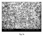
超硬合金成形体が次にしたがって製造された。円柱状のグリーン成形体が、94wt%のWCと6wt%のCoの組成を有する粉末から加圧成形された(直径12mm)。このWC原材料は、3.0μmの平均粒径を有する比較的粗い粒状である(FSSS)。全ての表面は薄い層(0.02gのCr3C2/cm2)を含んでいるCr3C2で覆われた。その後、この成形体は1350℃で30分の間焼結された。焼結の最後の15分間は、10MPaの等圧のガス圧力が、緻密ボディを得るため付加された。焼結されたボタンの断面が検査された。Cr3C2は表面に見ることはできなかった。図1は、上述のCr3C2で覆われた表面からの距離に対する硬さとコバルト含有量を示す。コバルト含有量は、表面近くが最も少なく、且つ最大値まで距離の増加とともに増加し、その後再び減少する。硬さは、表面近くで最も高くて、且つ最小値まで距離とともに減少し、その後中心に向かって再び増加する。図2は、上述のCr3C2で覆った表面までの距離に対するクロム含有量の図を示す。このクロム含有量は、表面近くで最も多くて且つ距離とともに減少する。図3aは、上述のCr3C2で覆われた表面から20μmの距離での微細組織を示す顕微鏡写真である(FEG−SEM、2000X、BSE様式)。図3bは、上述のCr3C2で覆われた表面から2.5mmの距離での微細組織を示す顕微鏡写真である(FEG−SEM、2000X、BSE様式)。図3cは、ボタンの内側部分(上述のCr3C2で覆われた表面から6mm)の微細組織を示す顕微鏡写真である(FEG−SEM、2000X、BSE様式)。インターセプト値の相加平均として測定されたWC粒径を表1に示す。
Example 1
A cemented carbide molded body was produced according to the following. A cylindrical green molded body was pressure molded from a powder having a composition of 94 wt% WC and 6 wt% Co (diameter 12 mm). This WC raw material is relatively coarse granular (FSSS) with an average particle size of 3.0 μm. All surfaces were covered with Cr 3 C 2 containing a thin layer (0.02 g Cr 3 C 2 / cm 2 ). Thereafter, this compact was sintered at 1350 ° C. for 30 minutes. During the last 15 minutes of sintering, an equal gas pressure of 10 MPa was applied to obtain a dense body. The cross section of the sintered button was inspected. Cr 3 C 2 could not be seen on the surface. FIG. 1 shows hardness and cobalt content with respect to the distance from the surface covered with Cr 3 C 2 described above. The cobalt content is least near the surface and increases with increasing distance to the maximum value and then decreases again. The hardness is highest near the surface and decreases with distance to the minimum value and then increases again towards the center. FIG. 2 shows a diagram of chromium content versus distance to the surface covered with Cr 3 C 2 described above. This chromium content is highest near the surface and decreases with distance. FIG. 3a is a photomicrograph showing the microstructure at a distance of 20 μm from the surface covered with Cr 3 C 2 described above (FEG-SEM, 2000X, BSE format). FIG. 3b is a photomicrograph showing the microstructure at a distance of 2.5 mm from the Cr 3 C 2 covered surface (FEG-SEM, 2000X, BSE format). FIG. 3c is a photomicrograph (FEG-SEM, 2000X, BSE format) showing the microstructure of the inner part of the button (6 mm from the surface covered with Cr 3 C 2 described above). Table 1 shows the WC particle size measured as an arithmetic average of intercept values.
表1
表面からの距離(深さ) 平均粒径(μm)
20μm 1.5
2.5mm 1.8
6.0mm 1.8
Table 1
Distance from surface (depth) Average particle diameter (μm)
20 μm 1.5
2.5 mm 1.8
6.0 mm 1.8
Claims (5)
微細な粒径を有する上記表面部分が、上記内側部分より少ないバインダー相含有量を有し、
上記表面部分の因子A=((wt%Cr/wt%バインダー相)+0.01)と、超硬合金工具ボディの最も少ないCr含有量によって特徴つけられる部分で採取した因子B=((wt%Cr/wt%バインダー相)+0.01)との比率A/Bが1.5以上であるようにCrを含有し、
上記微細な粒径の前記表面部分と粗い粒径の前記内側部分の間でCo含有量が最大となることを特徴とする超硬合金工具ボディ。 Include C o or Rana Luba Indah hard constituents in the phase WC, at least one surface portion minutes及 beauty inner portion, the hard constituents WC is the grain size of the particle diameter of the inner part above the surface portion A smaller, mining and structural cemented carbide tool body,
The surface portion having a fine particle size has less binder phase content than the inner portion;
Factor A = ((wt% Cr / wt% binder phase) +0.01) of the surface portion and factor B = ((wt%) characterized by the smallest Cr content of the cemented carbide tool body Cr / wt% binder phase) +0.01) and Cr is contained so that the ratio A / B is 1.5 or more,
Cemented carbide tools body Co content between the surface portion and the inner portion of the coarse particle size of the fine particle size is characterized to be a maximum.
−単一種類のWC粉末とバインダー相を形成するためのCo粉末から超硬合金の成形体を加圧成形する工程、
−前記成形体の露出面の少なくとも一部分に、炭化クロムを含む粒精製剤の粉末を配置する工程、
−超硬合金工具ボディの中心に向かって前記粒精製剤が拡散するように、前記成形体及び粒精製剤の粉末を焼結することによって、前記粒精製剤を配置する露出面から内側に向かって表面部分と内側部分を形成すると共に、焼結工程の最後に等圧のガス圧力を可能な限り付加して、緻密な前記ボディを得る工程、
を含む耐摩耗性表面部分を備える超硬合金工具ボディを製造する方法であって、
前記内側部分のWC粒径とCo含有量より小さな粒径と少ない含有量を有する緻密領域が表面部分に得られる可能な限り短い時間、前記焼結工程が実施され、
表面部分の因子A=((wt%Cr/wt%バインダー相)+0.01)と、超硬合金工具ボディの最も少ないCr含有量によって特徴つけられる部分で採取した因子B=((wt%Cr/wt%バインダー相)+0.01)との比率A/Bが1.5以上であるようにCrを含有し、
上記微細な粒径の上記表面部分と粗い粒径の上記内側部分の間でCo含有量が最大となる超硬合金工具ボディを製造することを特徴とする超硬合金工具ボディを製造する方法。 Next step,
- a single type of process that the molded body pressure molding of the cemented carbide of Co powder to form a WC powder and a binder phase,
-Disposing a powder of a grain refiner containing chromium carbide on at least a part of the exposed surface of the molded body;
-Sintering the compact and the powder of the grain refiner so that the grain refiner diffuses toward the center of the cemented carbide tool body, from the exposed surface on which the grain refiner is placed inward. Forming a surface portion and an inner portion, and applying a gas pressure of equal pressure as much as possible at the end of the sintering step to obtain a dense body ,
A method of manufacturing a cemented carbide tool body comprising a wear resistant surface portion comprising:
Shorter time as possible dense region having a WC grain size and smaller particle size than the Co content less I含 chromatic amount of the inner portion can be obtained in a surface portion, wherein the sintering step is performed,
Surface factor A = ((wt% Cr / wt% binder phase) +0.01) and factor B = ((wt% Cr) characterized by the lowest Cr content of the cemented carbide tool body / Wt% binder phase) +0.01) and Cr is contained so that the ratio A / B is 1.5 or more,
Method of making a cemented carbide tool body, characterized in that the Co content between the surface portion and the inner portion of the coarse particle size of the fine particle size to produce a cemented carbide tool body becomes maximum.
Applications Claiming Priority (5)
| Application Number | Priority Date | Filing Date | Title |
|---|---|---|---|
| SE0303360A SE526601C2 (en) | 2003-12-15 | 2003-12-15 | Cemented carbide tool for metal cutting or metal forming, has main body with surface portion having smaller Wc grain size than interior portion and lower binder phase content than interior portion |
| SE0303360-2 | 2003-12-15 | ||
| SE0303486-5 | 2003-12-22 | ||
| SE0303486A SE526633C2 (en) | 2003-12-22 | 2003-12-22 | Cemented carbide tool insert/button for mining and construction for drilling/cutting of rock, mineral, asphalt, and concrete, comprises hard constituents in binder phase of cobalt and/or nickel and surface portion(s) and interior portion |
| PCT/SE2004/001817 WO2005056854A1 (en) | 2003-12-15 | 2004-12-07 | Cemented carbide tools for mining and construction applications and method of making the same |
Related Child Applications (1)
| Application Number | Title | Priority Date | Filing Date |
|---|---|---|---|
| JP2012214131A Division JP2013014846A (en) | 2003-12-15 | 2012-09-27 | Cemented carbide tool for mining and construction application and method of making same |
Publications (3)
| Publication Number | Publication Date |
|---|---|
| JP2007522339A JP2007522339A (en) | 2007-08-09 |
| JP2007522339A5 JP2007522339A5 (en) | 2008-01-31 |
| JP5448300B2 true JP5448300B2 (en) | 2014-03-19 |
Family
ID=34680755
Family Applications (2)
| Application Number | Title | Priority Date | Filing Date |
|---|---|---|---|
| JP2006545279A Active JP5448300B2 (en) | 2003-12-15 | 2004-12-07 | Cemented carbide tool for mining and construction, and manufacturing method thereof |
| JP2012214131A Pending JP2013014846A (en) | 2003-12-15 | 2012-09-27 | Cemented carbide tool for mining and construction application and method of making same |
Family Applications After (1)
| Application Number | Title | Priority Date | Filing Date |
|---|---|---|---|
| JP2012214131A Pending JP2013014846A (en) | 2003-12-15 | 2012-09-27 | Cemented carbide tool for mining and construction application and method of making same |
Country Status (10)
| Country | Link |
|---|---|
| US (2) | US7427310B2 (en) |
| EP (1) | EP1697551B1 (en) |
| JP (2) | JP5448300B2 (en) |
| KR (1) | KR101387183B1 (en) |
| AU (1) | AU2004297495B2 (en) |
| CA (1) | CA2547926C (en) |
| IL (1) | IL176003A (en) |
| RU (1) | RU2364700C2 (en) |
| WO (1) | WO2005056854A1 (en) |
| ZA (1) | ZA200604825B (en) |
Families Citing this family (21)
| Publication number | Priority date | Publication date | Assignee | Title |
|---|---|---|---|---|
| ATE389737T1 (en) * | 2003-12-15 | 2008-04-15 | Sandvik Intellectual Property | SINTERED CARBIDE INSERT AND METHOD FOR PRODUCING IT. |
| GB0816837D0 (en) * | 2008-09-15 | 2008-10-22 | Element Six Holding Gmbh | A Hard-Metal |
| GB0816836D0 (en) | 2008-09-15 | 2008-10-22 | Element Six Holding Gmbh | Steel wear part with hard facing |
| AU2013273604B2 (en) * | 2008-11-11 | 2015-12-03 | Sandvik Intellectual Property Ab | Cemented carbide body and method |
| EP2184122A1 (en) * | 2008-11-11 | 2010-05-12 | Sandvik Intellectual Property AB | Cemented carbide body and method |
| US8328654B2 (en) * | 2009-01-21 | 2012-12-11 | Taylor Made Golf Company, Inc. | Golf club head |
| GB0903343D0 (en) † | 2009-02-27 | 2009-04-22 | Element Six Holding Gmbh | Hard-metal body with graded microstructure |
| US20120177453A1 (en) | 2009-02-27 | 2012-07-12 | Igor Yuri Konyashin | Hard-metal body |
| US8216677B2 (en) | 2009-03-30 | 2012-07-10 | Us Synthetic Corporation | Polycrystalline diamond compacts, methods of making same, and applications therefor |
| US9555506B2 (en) * | 2012-02-28 | 2017-01-31 | Kyocera Corporation | Drill blank, method for manufacturing drill blank, drill, and method for manufacturing drill |
| JP5825677B2 (en) * | 2012-03-07 | 2015-12-02 | 株式会社日立製作所 | Course control program generation method and computer system |
| RU2539722C1 (en) * | 2013-06-20 | 2015-01-27 | Анатолий Борисович Коршунов | Hard alloy cobalt-containing removable cover plate for centrifuge screw reinforcement |
| RU2620218C2 (en) * | 2014-12-18 | 2017-05-23 | Федеральное государственное бюджетное образовательное учреждение высшего профессионального образования "Московский государственный университет имени М.В. Ломоносова" (МГУ) | Method of forming wear-resistant surface layer in cobalt-containing material |
| WO2016174028A1 (en) * | 2015-04-30 | 2016-11-03 | Sandvik Intellectual Property Ab | Cutting tool |
| CN104874797B (en) * | 2015-06-05 | 2017-08-25 | 西迪技术股份有限公司 | A kind of forming method of hard alloy FGM |
| CN109790076B (en) * | 2016-09-28 | 2022-07-08 | 山特维克知识产权股份有限公司 | Rock drill blade |
| KR102491413B1 (en) * | 2016-11-08 | 2023-01-20 | 산드빅 인터렉츄얼 프로퍼티 에이비 | Methods for processing Ti, Ti alloys and Ni-based alloys |
| ES2947357T3 (en) * | 2018-03-27 | 2023-08-07 | Sandvik Mining And Construction Tools Ab | rock drilling insert |
| CN109085661B (en) * | 2018-08-06 | 2020-01-10 | 金川集团股份有限公司 | Method for analyzing mining potential of hydrous silicate type laterite-nickel ore |
| EP3653743A1 (en) * | 2018-11-14 | 2020-05-20 | Sandvik Mining and Construction Tools AB | Binder redistribution within a cemented carbide mining insert |
| JP7111262B2 (en) * | 2020-05-26 | 2022-08-02 | 住友電気工業株式会社 | Cutting tools |
Family Cites Families (29)
| Publication number | Priority date | Publication date | Assignee | Title |
|---|---|---|---|---|
| US4359335A (en) | 1980-06-05 | 1982-11-16 | Smith International, Inc. | Method of fabrication of rock bit inserts of tungsten carbide (WC) and cobalt (Co) with cutting surface wear pad of relative hardness and body portion of relative toughness sintered as an integral composite |
| DE3574738D1 (en) | 1984-11-13 | 1990-01-18 | Santrade Ltd | SINDERED HARD METAL ALLOY FOR STONE DRILLING AND CUTTING MINERALS. |
| EP0194018A1 (en) * | 1985-01-31 | 1986-09-10 | Boart International Limited | Forming components made of hard metal |
| SE453202B (en) * | 1986-05-12 | 1988-01-18 | Sandvik Ab | SINTER BODY FOR CUTTING PROCESSING |
| JPS6338501A (en) * | 1986-08-05 | 1988-02-19 | Sumitomo Metal Mining Co Ltd | Composite sintered hard alloy and its production |
| JPS6338502A (en) * | 1986-08-05 | 1988-02-19 | Sumitomo Metal Mining Co Ltd | Composite sintered hard alloy and its manufacture |
| US4705124A (en) * | 1986-08-22 | 1987-11-10 | Minnesota Mining And Manufacturing Company | Cutting element with wear resistant crown |
| US4990410A (en) | 1988-05-13 | 1991-02-05 | Toshiba Tungaloy Co., Ltd. | Coated surface refined sintered alloy |
| US5181953A (en) | 1989-12-27 | 1993-01-26 | Sumitomo Electric Industries, Ltd. | Coated cemented carbides and processes for the production of same |
| JP2762745B2 (en) * | 1989-12-27 | 1998-06-04 | 住友電気工業株式会社 | Coated cemented carbide and its manufacturing method |
| JP3046336B2 (en) * | 1990-09-17 | 2000-05-29 | 東芝タンガロイ株式会社 | Sintered alloy with graded composition and method for producing the same |
| JP3080983B2 (en) * | 1990-11-21 | 2000-08-28 | 東芝タンガロイ株式会社 | Hard sintered alloy having gradient composition structure and method for producing the same |
| SE9004124D0 (en) | 1990-12-21 | 1990-12-21 | Sandvik Ab | HARD METAL TOOLS FOR CUTTING AND CUTTING |
| JPH0726173B2 (en) | 1991-02-13 | 1995-03-22 | 東芝タンガロイ株式会社 | High toughness cermet and method for producing the same |
| SE500050C2 (en) * | 1991-02-18 | 1994-03-28 | Sandvik Ab | Carbide body for abrasive mineral felling and ways of making it |
| EP0822265B1 (en) | 1994-05-19 | 2001-10-17 | Sumitomo Electric Industries, Ltd. | Nitrogen-containing sintered hard alloy |
| US5541006A (en) * | 1994-12-23 | 1996-07-30 | Kennametal Inc. | Method of making composite cermet articles and the articles |
| US5623723A (en) * | 1995-08-11 | 1997-04-22 | Greenfield; Mark S. | Hard composite and method of making the same |
| SE513740C2 (en) * | 1995-12-22 | 2000-10-30 | Sandvik Ab | Durable hair metal body mainly for use in rock drilling and mineral mining |
| JPH09203285A (en) * | 1996-01-30 | 1997-08-05 | Tone Corp | Multi-layer cemented carbide chip and production |
| US5743515A (en) * | 1996-03-29 | 1998-04-28 | Wodell; William Roy | Material handling apparatus |
| SE509566C2 (en) * | 1996-07-11 | 1999-02-08 | Sandvik Ab | sintering Method |
| SE506949C2 (en) | 1996-07-19 | 1998-03-09 | Sandvik Ab | Carbide tools with borated surface zone and its use for cold working operations |
| SE509560C2 (en) * | 1996-09-06 | 1999-02-08 | Sandvik Ab | Coated cemented carbide inserts for machining cast iron |
| SE510763C2 (en) | 1996-12-20 | 1999-06-21 | Sandvik Ab | Topic for a drill or a metal cutter for machining |
| DE69818097T2 (en) | 1997-12-17 | 2004-07-08 | A.W. Chesterton Co., Stoneham | FEEDBACK PRESSURE CONTROL SYSTEM FOR MECHANICAL SEAL |
| JP2000160266A (en) * | 1998-11-25 | 2000-06-13 | Fuji Dies Kk | Tungsten carbide based cemented carbide of incremental composition, its manufacture and its application tool |
| AT5837U1 (en) * | 2002-04-17 | 2002-12-27 | Plansee Tizit Ag | HARD METAL COMPONENT WITH GRADED STRUCTURE |
| ATE389737T1 (en) | 2003-12-15 | 2008-04-15 | Sandvik Intellectual Property | SINTERED CARBIDE INSERT AND METHOD FOR PRODUCING IT. |
-
2004
- 2004-12-07 RU RU2006125430/02A patent/RU2364700C2/en active
- 2004-12-07 KR KR1020067012399A patent/KR101387183B1/en active IP Right Grant
- 2004-12-07 AU AU2004297495A patent/AU2004297495B2/en active Active
- 2004-12-07 EP EP04801724.8A patent/EP1697551B1/en active Active
- 2004-12-07 JP JP2006545279A patent/JP5448300B2/en active Active
- 2004-12-07 CA CA2547926A patent/CA2547926C/en active Active
- 2004-12-07 WO PCT/SE2004/001817 patent/WO2005056854A1/en active Application Filing
- 2004-12-15 US US11/011,137 patent/US7427310B2/en active Active
-
2006
- 2006-05-30 IL IL176003A patent/IL176003A/en not_active IP Right Cessation
- 2006-06-12 ZA ZA2006/04825A patent/ZA200604825B/en unknown
-
2008
- 2008-08-11 US US12/189,480 patent/US7678327B2/en active Active
-
2012
- 2012-09-27 JP JP2012214131A patent/JP2013014846A/en active Pending
Also Published As
| Publication number | Publication date |
|---|---|
| EP1697551A1 (en) | 2006-09-06 |
| AU2004297495B2 (en) | 2010-10-28 |
| KR20060123371A (en) | 2006-12-01 |
| WO2005056854A1 (en) | 2005-06-23 |
| EP1697551B1 (en) | 2015-07-22 |
| ZA200604825B (en) | 2011-11-30 |
| US20090014927A1 (en) | 2009-01-15 |
| RU2364700C2 (en) | 2009-08-20 |
| JP2007522339A (en) | 2007-08-09 |
| US7427310B2 (en) | 2008-09-23 |
| KR101387183B1 (en) | 2014-04-21 |
| AU2004297495A1 (en) | 2005-06-23 |
| JP2013014846A (en) | 2013-01-24 |
| CA2547926A1 (en) | 2005-06-23 |
| IL176003A0 (en) | 2006-10-05 |
| US20050147850A1 (en) | 2005-07-07 |
| US7678327B2 (en) | 2010-03-16 |
| CA2547926C (en) | 2013-08-06 |
| RU2006125430A (en) | 2008-01-27 |
| IL176003A (en) | 2011-07-31 |
Similar Documents
| Publication | Publication Date | Title |
|---|---|---|
| JP5448300B2 (en) | Cemented carbide tool for mining and construction, and manufacturing method thereof | |
| US7493973B2 (en) | Polycrystalline diamond materials having improved abrasion resistance, thermal stability and impact resistance | |
| JP3332928B2 (en) | Composite cermet product and method for producing the same | |
| CN103752833B (en) | Cemented carbide body and method | |
| KR20120070550A (en) | Cemented carbide tool and method of making the same | |
| JP2003328067A (en) | Cemented carbide structure member having structure showing gradual transition | |
| JP2012506493A (en) | Polycrystalline diamond composite shaped element, tool incorporating the same, and method of making the same | |
| JP6806792B2 (en) | Sintered carbide with a structure that increases toughness | |
| US8206474B2 (en) | Abrasive compacts | |
| JP2007522339A5 (en) | ||
| CN114080285A (en) | Gradient cemented carbide body and method for manufacturing same | |
| JP2012519232A (en) | Carbide element, tool including the same, and method of manufacturing such a carbide element | |
| IL163761A (en) | Cutting tool | |
| WO2023274818A1 (en) | Method of making a powder for additive manufacturing | |
| SE526601C2 (en) | Cemented carbide tool for metal cutting or metal forming, has main body with surface portion having smaller Wc grain size than interior portion and lower binder phase content than interior portion | |
| JP5087776B2 (en) | Method for producing a composite diamond body | |
| JPH04147939A (en) | Sintered hard alloy and its manufacture | |
| JPH09203285A (en) | Multi-layer cemented carbide chip and production | |
| SE526633C2 (en) | Cemented carbide tool insert/button for mining and construction for drilling/cutting of rock, mineral, asphalt, and concrete, comprises hard constituents in binder phase of cobalt and/or nickel and surface portion(s) and interior portion | |
| SE526633C3 (en) |
Legal Events
| Date | Code | Title | Description |
|---|---|---|---|
| A521 | Request for written amendment filed |
Free format text: JAPANESE INTERMEDIATE CODE: A523 Effective date: 20071207 |
|
| A621 | Written request for application examination |
Free format text: JAPANESE INTERMEDIATE CODE: A621 Effective date: 20071207 |
|
| A131 | Notification of reasons for refusal |
Free format text: JAPANESE INTERMEDIATE CODE: A131 Effective date: 20110222 |
|
| A601 | Written request for extension of time |
Free format text: JAPANESE INTERMEDIATE CODE: A601 Effective date: 20110520 |
|
| A602 | Written permission of extension of time |
Free format text: JAPANESE INTERMEDIATE CODE: A602 Effective date: 20110527 |
|
| A521 | Request for written amendment filed |
Free format text: JAPANESE INTERMEDIATE CODE: A523 Effective date: 20110811 |
|
| A02 | Decision of refusal |
Free format text: JAPANESE INTERMEDIATE CODE: A02 Effective date: 20120529 |
|
| A521 | Request for written amendment filed |
Free format text: JAPANESE INTERMEDIATE CODE: A523 Effective date: 20120927 |
|
| A911 | Transfer to examiner for re-examination before appeal (zenchi) |
Free format text: JAPANESE INTERMEDIATE CODE: A911 Effective date: 20121009 |
|
| A912 | Re-examination (zenchi) completed and case transferred to appeal board |
Free format text: JAPANESE INTERMEDIATE CODE: A912 Effective date: 20121122 |
|
| A521 | Request for written amendment filed |
Free format text: JAPANESE INTERMEDIATE CODE: A523 Effective date: 20131105 |
|
| A61 | First payment of annual fees (during grant procedure) |
Free format text: JAPANESE INTERMEDIATE CODE: A61 Effective date: 20131224 |
|
| R150 | Certificate of patent or registration of utility model |
Ref document number: 5448300 Country of ref document: JP Free format text: JAPANESE INTERMEDIATE CODE: R150 Free format text: JAPANESE INTERMEDIATE CODE: R150 |
|
| R250 | Receipt of annual fees |
Free format text: JAPANESE INTERMEDIATE CODE: R250 |
|
| R250 | Receipt of annual fees |
Free format text: JAPANESE INTERMEDIATE CODE: R250 |
|
| R250 | Receipt of annual fees |
Free format text: JAPANESE INTERMEDIATE CODE: R250 |
|
| R250 | Receipt of annual fees |
Free format text: JAPANESE INTERMEDIATE CODE: R250 |
|
| R250 | Receipt of annual fees |
Free format text: JAPANESE INTERMEDIATE CODE: R250 |
|
| R250 | Receipt of annual fees |
Free format text: JAPANESE INTERMEDIATE CODE: R250 |
|
| R250 | Receipt of annual fees |
Free format text: JAPANESE INTERMEDIATE CODE: R250 |
|
| R250 | Receipt of annual fees |
Free format text: JAPANESE INTERMEDIATE CODE: R250 |