JP5448253B2 - LED lamp - Google Patents
LED lamp Download PDFInfo
- Publication number
- JP5448253B2 JP5448253B2 JP2011014841A JP2011014841A JP5448253B2 JP 5448253 B2 JP5448253 B2 JP 5448253B2 JP 2011014841 A JP2011014841 A JP 2011014841A JP 2011014841 A JP2011014841 A JP 2011014841A JP 5448253 B2 JP5448253 B2 JP 5448253B2
- Authority
- JP
- Japan
- Prior art keywords
- led lamp
- light source
- source support
- led
- gas
- Prior art date
- Legal status (The legal status is an assumption and is not a legal conclusion. Google has not performed a legal analysis and makes no representation as to the accuracy of the status listed.)
- Active
Links
- 239000007789 gas Substances 0.000 claims description 64
- 239000000758 substrate Substances 0.000 claims description 56
- 239000011521 glass Substances 0.000 claims description 27
- 229910052751 metal Inorganic materials 0.000 claims description 27
- 239000002184 metal Substances 0.000 claims description 27
- 229920005989 resin Polymers 0.000 claims description 19
- 239000011347 resin Substances 0.000 claims description 19
- 239000001307 helium Substances 0.000 claims description 16
- 229910052734 helium Inorganic materials 0.000 claims description 16
- SWQJXJOGLNCZEY-UHFFFAOYSA-N helium atom Chemical compound [He] SWQJXJOGLNCZEY-UHFFFAOYSA-N 0.000 claims description 16
- 229910052782 aluminium Inorganic materials 0.000 claims description 11
- XAGFODPZIPBFFR-UHFFFAOYSA-N aluminium Chemical compound [Al] XAGFODPZIPBFFR-UHFFFAOYSA-N 0.000 claims description 11
- RYGMFSIKBFXOCR-UHFFFAOYSA-N Copper Chemical compound [Cu] RYGMFSIKBFXOCR-UHFFFAOYSA-N 0.000 claims description 10
- 229910052802 copper Inorganic materials 0.000 claims description 10
- 239000010949 copper Substances 0.000 claims description 10
- 230000001133 acceleration Effects 0.000 claims description 6
- UFHFLCQGNIYNRP-UHFFFAOYSA-N Hydrogen Chemical compound [H][H] UFHFLCQGNIYNRP-UHFFFAOYSA-N 0.000 claims description 5
- 229910052754 neon Inorganic materials 0.000 claims description 3
- GKAOGPIIYCISHV-UHFFFAOYSA-N neon atom Chemical compound [Ne] GKAOGPIIYCISHV-UHFFFAOYSA-N 0.000 claims description 3
- 238000001816 cooling Methods 0.000 description 16
- 230000017525 heat dissipation Effects 0.000 description 12
- 238000012546 transfer Methods 0.000 description 12
- 238000004519 manufacturing process Methods 0.000 description 9
- 238000010586 diagram Methods 0.000 description 8
- 230000000694 effects Effects 0.000 description 8
- 230000002093 peripheral effect Effects 0.000 description 7
- 238000000034 method Methods 0.000 description 6
- 238000007789 sealing Methods 0.000 description 5
- 238000005259 measurement Methods 0.000 description 4
- 239000004020 conductor Substances 0.000 description 3
- 239000004065 semiconductor Substances 0.000 description 3
- 239000000853 adhesive Substances 0.000 description 2
- 230000001070 adhesive effect Effects 0.000 description 2
- 230000008901 benefit Effects 0.000 description 2
- 230000000052 comparative effect Effects 0.000 description 2
- 238000005286 illumination Methods 0.000 description 2
- 230000007774 longterm Effects 0.000 description 2
- 239000000463 material Substances 0.000 description 2
- 229910001507 metal halide Inorganic materials 0.000 description 2
- 150000005309 metal halides Chemical class 0.000 description 2
- 238000007747 plating Methods 0.000 description 2
- 239000000843 powder Substances 0.000 description 2
- 150000003839 salts Chemical class 0.000 description 2
- 239000000126 substance Substances 0.000 description 2
- IJGRMHOSHXDMSA-UHFFFAOYSA-N Atomic nitrogen Chemical compound N#N IJGRMHOSHXDMSA-UHFFFAOYSA-N 0.000 description 1
- 229920000049 Carbon (fiber) Polymers 0.000 description 1
- 238000007792 addition Methods 0.000 description 1
- QVGXLLKOCUKJST-UHFFFAOYSA-N atomic oxygen Chemical compound [O] QVGXLLKOCUKJST-UHFFFAOYSA-N 0.000 description 1
- 238000005452 bending Methods 0.000 description 1
- 230000005540 biological transmission Effects 0.000 description 1
- 239000005388 borosilicate glass Substances 0.000 description 1
- 239000004917 carbon fiber Substances 0.000 description 1
- 239000000919 ceramic Substances 0.000 description 1
- 230000007423 decrease Effects 0.000 description 1
- 238000012217 deletion Methods 0.000 description 1
- 230000037430 deletion Effects 0.000 description 1
- 230000006866 deterioration Effects 0.000 description 1
- 238000011161 development Methods 0.000 description 1
- 238000004512 die casting Methods 0.000 description 1
- 238000009792 diffusion process Methods 0.000 description 1
- 229910001873 dinitrogen Inorganic materials 0.000 description 1
- 238000010292 electrical insulation Methods 0.000 description 1
- 238000005516 engineering process Methods 0.000 description 1
- 239000003822 epoxy resin Substances 0.000 description 1
- 239000005338 frosted glass Substances 0.000 description 1
- 230000020169 heat generation Effects 0.000 description 1
- 230000006872 improvement Effects 0.000 description 1
- 238000007689 inspection Methods 0.000 description 1
- VNWKTOKETHGBQD-UHFFFAOYSA-N methane Chemical compound C VNWKTOKETHGBQD-UHFFFAOYSA-N 0.000 description 1
- 239000010445 mica Substances 0.000 description 1
- 229910052618 mica group Inorganic materials 0.000 description 1
- 238000012986 modification Methods 0.000 description 1
- 230000004048 modification Effects 0.000 description 1
- 230000001151 other effect Effects 0.000 description 1
- 239000001301 oxygen Substances 0.000 description 1
- 229910052760 oxygen Inorganic materials 0.000 description 1
- 238000010422 painting Methods 0.000 description 1
- 238000000059 patterning Methods 0.000 description 1
- 229920005668 polycarbonate resin Polymers 0.000 description 1
- 239000004431 polycarbonate resin Substances 0.000 description 1
- 229920000647 polyepoxide Polymers 0.000 description 1
- 230000005855 radiation Effects 0.000 description 1
- 230000009257 reactivity Effects 0.000 description 1
- 229910052710 silicon Inorganic materials 0.000 description 1
- 239000010703 silicon Substances 0.000 description 1
- 238000005476 soldering Methods 0.000 description 1
- 238000004381 surface treatment Methods 0.000 description 1
- 238000012360 testing method Methods 0.000 description 1
Images


Description
本発明は、LEDランプに関する。 The present invention relates to an LED lamp.
照明用ランプは、概して、白熱電球、蛍光灯、HIDランプ、LEDランプと開発され、実用化されてきた。LEDランプは、発光ダイオード素子を光源として利用したランプであり、青色LED素子の開発により白色の発光が可能となり、最近、照明用ランプとして利用が拡がりつつある。 In general, lighting lamps have been developed and put into practical use as incandescent bulbs, fluorescent lamps, HID lamps, and LED lamps. An LED lamp is a lamp that uses a light emitting diode element as a light source, and the development of a blue LED element enables white light emission, and recently, the use thereof is expanding as an illumination lamp.
図1は、このような現在広く販売されているLEDランプの一例を示す図である。これらのLEDランプ100は、一般に、出力が10W以下(典型的には7W程度)のランプである。図1(A)〜(C)に示すように、ランプ形状は種々あるが、基本的に、口金102、放熱部104及びグローブ106から成っている。放熱部104は、アルミニウムのダイキャストから形成され、多くの場合、外周面に放熱フィンの形状に形成されている。グローブ106は、透光性の樹脂から成る。一部に、ガラス製のグローブも見られる。アルミダイキャスト部分104とグローブ106との間は、適当な接着剤で固定されている。従って、アルミダイキャスト部分104とグローブ106とで形成される内部空間は、ランプ外部との間で気密封止になってない。
FIG. 1 is a diagram showing an example of such LED lamps that are currently widely sold. These
本発明者等は、次の先行特許文献が存在することを承知している。 The present inventors are aware that the following prior patent documents exist.
特許文献1は、ケース部材として樹脂及びガラスを例示し、ガラスを使用した場合は内部の発光ダイオードが外部環境から保護され、更にガラス容器内を水分を有しないガス(実施例では窒素ガス)を封入した場合には水分が残留せずガラスが曇らない効果を開示する。しかし、ここには、冷却・放熱手段としての低分子量ガスに関する記載・示唆は無い。 Patent Document 1 exemplifies resin and glass as a case member. When glass is used, an internal light-emitting diode is protected from the external environment, and further, a gas that does not contain moisture (nitrogen gas in the embodiment) is contained in the glass container. Disclosed is the effect that when encapsulated, no moisture remains and the glass is not fogged. However, there is no description or suggestion regarding a low molecular weight gas as a cooling / dissipating means.
特許文献2は、LEDランプを収納するバルブは樹脂材料から形成され、図1に関連して説明した気密封止に関する記載・示唆は無い。
In
特許文献3は、メタルハライドランプに関する発明であり、LED素子に関する記載・示唆は無い。 Patent Document 3 is an invention related to a metal halide lamp, and there is no description or suggestion regarding an LED element.
特許文献4は、透光性カバーはポリカーボネート樹脂製であり、放熱部はアルミ等の金属製である。図1に例示したLEDランプに該当し、気密封止に関する記載・示唆は無い。 In Patent Document 4, the translucent cover is made of polycarbonate resin, and the heat dissipation part is made of metal such as aluminum. This corresponds to the LED lamp illustrated in FIG. 1 and there is no description or suggestion regarding hermetic sealing.
LED素子は、半導体から成り、半導体の接合部の温度と素子寿命が密接な関係にある。即ち、使用時の接合部の温度が比較的低い場合には素子寿命は長期間となるが、温度が高くなるにつれ素子寿命は急激に短くなる。従って、LEDランプでは、LED素子の温度が高いとランプ寿命が短縮化し、ランプ照度も劣化する。 An LED element is made of a semiconductor, and the temperature of the junction of the semiconductor and the element lifetime are closely related. That is, when the temperature of the joint at the time of use is relatively low, the device lifetime becomes long, but as the temperature increases, the device lifetime decreases rapidly. Therefore, in the LED lamp, when the temperature of the LED element is high, the lamp life is shortened and the lamp illuminance is also deteriorated.
半導体素子を使用した電子機器においては冷却・放熱手段が重要事項であるのと同様に、LEDランプにおいても冷却・放熱手段が重要事項となる。 In an electronic device using a semiconductor element, the cooling / heat dissipating means is an important matter in the LED lamp as well as the cooling / heat dissipating means.
上記課題に鑑みて、本発明は、新規な冷却・放熱手段を備えたLEDランプを提供することを目的とする。 In view of the above problems, an object of the present invention is to provide an LED lamp provided with a novel cooling / dissipating means.
本発明に係るLEDランプは、複数個のLED素子と、前記LED素子を包囲するガラス製密封容器とを備え、該ガラス製密封容器の内部には低分子量ガスが封入されている。 The LED lamp according to the present invention includes a plurality of LED elements and a glass sealed container surrounding the LED elements, and a low molecular weight gas is sealed inside the glass sealed container.
更に、上記LEDランプでは、前記低分子量ガスは、ヘリウムガス、水素ガス、ネオンガス又はこれらの任意の組み合わせの混合ガスのいずれかを含んでいてもよい。 Furthermore, in the LED lamp, the low molecular weight gas may include any one of helium gas, hydrogen gas, neon gas, or a mixed gas of any combination thereof.
更に、上記LEDランプでは、前記ガラス製密封容器の端部には口金が形成され、容器の内部と外部との間は気密状態が保持されていてもよい。 Further, in the LED lamp, a base may be formed at an end of the glass sealed container, and an airtight state may be maintained between the inside and the outside of the container.
更に、上記LEDランプでは、更に、軸線方向に沿って貫通孔を有する棒状体の光源支持体を備え、前記複数個のLED素子は、前記光源支持体の側面に固定され、前記光源支持体の開孔は、前記低分子量ガスが流れるガス流路を形成していてもよい。 Furthermore, the LED lamp further includes a rod-shaped light source support having a through hole along the axial direction, and the plurality of LED elements are fixed to a side surface of the light source support, The opening may form a gas flow path through which the low molecular weight gas flows.
更に、上記LEDランプでは、前記光源支持体は、断面形状が多角形であってよい。 Furthermore, in the LED lamp, the light source support may have a polygonal cross-sectional shape.
更に、上記LEDランプでは、更に、前記光源支持体の貫通孔の上端、下端又はその両方の近傍にガス流加速ファンを備えていてもよい。 Further, the LED lamp may further include a gas flow acceleration fan in the vicinity of the upper end, the lower end, or both of the through hole of the light source support.
更に、上記LEDランプでは、前記光源支持体は、少なくとも、アルミニウム、銅、又は熱伝導樹脂を含む良好な熱伝導性を有する部材から成っていてもよい。 Furthermore, in the LED lamp, the light source support may be made of a member having good thermal conductivity including at least aluminum, copper, or a heat conductive resin.
更に、上記LEDランプでは、前記光源支持体には、前記複数個のLEDが搭載された実装基板が固定されていてもよい。 Furthermore, in the LED lamp, a mounting substrate on which the plurality of LEDs are mounted may be fixed to the light source support.
更に、上記LEDランプでは、前記実装基板は、金属ベース基板又は金属コア基板であってもよい。 Furthermore, in the LED lamp, the mounting substrate may be a metal base substrate or a metal core substrate.
更に、上記LEDランプでは、更に、複数枚の矩形の基板を備え、前記基板は、全体としてガス流路を形成するように側端部を相互接続し、前記複数個のLED素子は、前記複数枚の矩形の基板の表面に夫々搭載されていてもよい。 Further, the LED lamp further includes a plurality of rectangular substrates, the substrates are interconnected at side ends so as to form a gas flow path as a whole, and the plurality of LED elements are the plurality of the LED elements. Each may be mounted on the surface of a rectangular substrate.
更に、上記LEDランプでは、更に、前記口金とは反対側である前記ガラス製密封容器のトップ部内側に、前記光源支持体に対して固定された熱伝導樹脂から成る伝熱器を備え、該光源支持体には、前記開口を流れるガス流の出入り可能な孔が形成されていてもよい。 Furthermore, the LED lamp further includes a heat exchanger made of a heat conductive resin fixed to the light source support on the inside of the top portion of the glass sealed container that is opposite to the base. The light source support may have a hole through which the gas flow flowing through the opening can enter and exit.
更に、上記LEDランプでは、更に、前記ガラス製密封容器のトップ部外側に、前記伝熱器に前記ガラス製密封容器を挟んで熱的伝導関係にある追加熱放熱器を備えていてもよい。 Further, the LED lamp may further include an additional heat radiator that is in a heat conduction relationship with the glass sealed container sandwiched between the heat transfer devices on the outer side of the top portion of the glass sealed container.
本発明によれば、新規な冷却・放熱手段を備えたLEDランプを提供することが出来る。 ADVANTAGE OF THE INVENTION According to this invention, the LED lamp provided with the novel cooling and heat dissipation means can be provided.
以下、本発明に係るLEDランプの実施形態に付いて、添付の図面を参照しながら詳細に説明する。なお、図中、同じ要素に対しては同じ参照符号を付して、重複した説明を省略する。また、以下に説明する実施形態は、例示であって、本発明の範囲を限定するものではないことを承知されたい。 Hereinafter, embodiments of an LED lamp according to the present invention will be described in detail with reference to the accompanying drawings. In the drawings, the same elements are denoted by the same reference numerals, and redundant description is omitted. In addition, it should be understood that the embodiments described below are examples and do not limit the scope of the present invention.
[第1実施形態]
(LEDランプの構成)
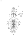
図2は、本実施形態に係るLEDランプ10を説明する図である。このLEDランプ10は、図1で説明した現在広く宣伝・販売されている7W程度の低出力LEDランプではなく、主として高出力の20W程度のLEDランプを対象としている。このため、冷却・放熱手段が更に重要な検討事項となる。
[First Embodiment]
(Configuration of LED lamp)
FIG. 2 is a diagram illustrating the
図2(A)に示すLEDランプ10は、一端が口金2で気密封止された外球6の内部に、複数個のLED素子18が配置されている。複数個のLED素子18は、実装基板16に適当な間隔で搭載され、この実装基板は光源支持体14に固定されている。
In the
更に、この光源支持体14は、外球6の一端に固着されたステム8から延在する支柱20によって、外球6の内部の適当な箇所に位置決め支持されている。光源支持体14に隣接する支柱20の部分には、絶縁性チューブ12が被せられ、光源支持体14と支柱20との間の電気絶縁性を確保している。光源支持体14及び実装基板16に関しては、後で、図3を参照しながら説明する。
Further, the
更に、口金2に近い外球6の内部には、熱遮蔽部材24が設けられている。図2(B)に示すように、熱遮蔽部材24は、外球6の内部形状に適合する概して円板状の部材であり、電気リード線及び支柱20を通す開口24a,24b,24cが形成されている。熱遮蔽部材24は、例えば、セラミック、金属板、マイカ板等で形成されている。熱遮蔽部材24の機能に関しては、後で、図4の製造方法に関連して説明する。
Further, a
外球6の内部空間22には、低分子量ガスが封入されている。本出願書類で「低分子量ガス」とは、比熱が大きく、熱伝導性が良好なガスであり、典型的にはヘリウムガスである。更に、ネオンガス、水素ガス、又はこれらの混合ガスであってもよい。特に、水素ガスは反応性が高いため、これを抑制した水素ガスとヘリウムガスとの混合ガスとしてもよい。
A low molecular weight gas is sealed in the
光源支持体14の下方には、所望により、ガス流加速用ファン32を設けてもよい。このガス流加速用ファン32は、光源支持体14の上方に設けてもよく、下方と上方の両方に設けてもよい。低分子量ガス及びガス流加速用ファン32に関しては、後で、図6に関連して説明する。
A gas
(各構成要素の説明)
図2(A)に示すLEDランプ10の各要素に関して説明する。
(Description of each component)
Each element of the
口金2は、白熱電球やHIDランプで使用されているねじ込みタイプや差し込みタイプであってよい。外球6は、例えば、ホウケイ酸ガラス等の透光性の硬質ガラスから成るBT管である。しかし、外球6の形状はこれに限定されず、任意の形状であってよい。外球6は、透明タイプ又は拡散タイプ(外球内表面を梨地状に処理した曇りガラスのタイプ)のいずれであってもよい。公知の白熱電球やHIDランプと同様に、口金2と外球6との間は気密封止され、外球内部と外部との間は気密封止状態となっている。
The
図3の(A)と(B)に、光源支持体14及び実装基板16の二つの例を示して、説明する。光源支持体14は、熱伝導性の良好な材質から成り、例えば、銅、アルミニウム、熱伝導樹脂等から成る。熱伝導樹脂は、樹脂に金属粉・金属片を混入して熱伝導係数を高くしたものである。
3A and 3B, two examples of the
図3(A)及び(B)に示すように、光源支持体14の外形は、棒状体であり、軸線方向に沿って貫通孔15a,15bが形成されている。図示する光源支持体14の軸線に直交する断面形状は、四角形であるが、これに限定されない。しかし、光源支持体14に対して実装基板16を面接触状態で固定するため、断面形状は多角形であることが好ましい。即ち、三角形、五角形、…等の任意の多角形であってよい。断面形状を円形、楕円形等にする場合には、光源支持体14と実装基板16との間に適当な熱伝導性の良好な介在物を設けることが好ましい。
As shown in FIGS. 3A and 3B, the outer shape of the
良好な熱伝導性の角材14aに、軸線に沿って円形の貫通孔15aを形成して光源支持体としてもよく(図3(A)参照)、角材14bに四角形の貫通孔15bを形成してもよい(図3(B)参照)。或いは、角材に貫通孔を形成するのではなく、板状体を90度ずつ三回折り曲げ両端部を接続して形成してもよく、4片の矩形の板状体を用意し、端部を適当な方法で相互に接続して、図3(B)に図示するような形状にしてもよい。
A circular through
光源支持体14の外周側面には、実装基板16が固定されている。所望により、光源支持体14の外周側面と実装基板16の間に、熱伝導シート21を介在配置してもよい。光源支持体14の断面形状がn角形であれば、n個の外周側面の全てに実装基板16が夫々固定される。
A mounting
各実装基板16には、複数個のLED素子(例えば、18−1〜18−4)が搭載されている。実装基板16は、プリント配線板から成り、LED素子に給電するための必要な回路パターが形成されている。LED素子18の放熱・冷却効果を高めるため、実装基板16は、板厚を比較的薄くするか、或いは金属ベース基板又は金属コア基板として形成することが好ましい。プリント配線板の技術分野に於いて、金属ベース基板又は金属コア基板自体は公知の技術である。通常のプリント配線板が、ガラスエポキシ樹脂製のコア基板に銅の回路パターンが形成されているのに対して、金属ベース基板は一方の面が金属板(銅、アルミニウム等)で、他方の面は絶縁性樹脂で被覆されている。金属コア基板は、金属板に所望により開孔を形成し、表裏及び開孔内を絶縁性樹脂で被覆されている。いずれかの基板の絶縁性樹脂層の上に回路パターンを形成する。金属の良好な熱伝導性により、著しい放熱・冷却効果が期待できる。
A plurality of LED elements (for example, 18-1 to 18-4) are mounted on each mounting
実装基板16に対するLED素子18の搭載は、半田付け等の公知の方法によって行われる。複数個のLED素子は、全て直列接続され、その両端がリード線を介して口金2につながっている。口金2は、ソケット(図示せず。)にねじ込み又は差し込まれ、各LED素子に所定の電圧が印加されるように所定の電圧源(図示せず。)に接続される。ガス流加速用ファン32を用いる場合も、同じ電圧源により駆動される。
The
(LEDランプの製造方法)
図4は、図2(A)に示すLEDランプ10の製造方法のフローであり、各ステップの右側にその段階の簡単なランプの図を示している。
(LED lamp manufacturing method)
FIG. 4 is a flow of a manufacturing method of the
ステップS1のマウント組立て工程で、LED素子18を実装基板16に搭載し、これを光源支持体14に固定し、光源支持体を支柱20に取り付けてマウントを形成、下端にステム8を取り付ける。
In the mount assembling step of step S1, the
ステップS2の封止工程で、マウントを外球6の内部に挿入し、マウントの下部のステム8と外球6とをバーナーで熱して、封着する。
In the sealing step of step S2, the mount is inserted into the
ステップS3の排気行程で、封止済みの外球内部を排気管を通じて一度真空状態に排気する。その後、低分子量ガスを封入し、チップオフ(排気管をバーナーで溶かして封着すること)する。 In the exhaust stroke of step S3, the sealed outer sphere is once exhausted to a vacuum state through the exhaust pipe. Thereafter, low molecular weight gas is sealed and the chip is turned off (the exhaust pipe is melted and sealed with a burner).
ステップS4の口金付け工程で、口金2のトップ部及びサイド部を半田付けする。
The top part and the side part of the
ステップS5の点灯試験、検査を経て、LEDランプ10が完成する。
The
ここで、ステップS2〜S4では、口金、外球の取り付け部、ステム等がバーナーによって1000℃近くの高温に熱せられる。この熱が、外球内部のLED素子に伝わって損傷しないようにするため、熱遮蔽部材24(図2(B)参照)が、外球の口金取り付け部分とLED素子との間に設けられている。 Here, in steps S2 to S4, the base, the outer sphere mounting portion, the stem and the like are heated to a high temperature close to 1000 ° C. by the burner. In order to prevent this heat from being transferred to the LED element inside the outer sphere and being damaged, a heat shielding member 24 (see FIG. 2B) is provided between the base mounting portion of the outer sphere and the LED element. Yes.
[第2実施形態]
第2実施形態は、光源支持体兼実装基板(14,16)を採用する点で、第1実施形態と異なる。即ち、第1実施形態では、光源支持体14と実装基板16とを別物としている。ここで、実装基板16は、好ましくは金属ベース基板又は金属コア基板である。従って、光源支持体14を実装基板16の金属部材と兼用して、光源支持体14を実装基板16の一部にすることができる。
[Second Embodiment]
The second embodiment differs from the first embodiment in that a light source support / mounting substrate (14, 16) is employed. That is, in the first embodiment, the
図に示していないが、具体的には、予め、回路パターンを形成した矩形の金属ベース基板又は金属コア基板を4枚用意する。4枚の基板を、全体としてガス流路を形成するように金属部材の端部を相互に適当な方法で接続して、光源支持体兼実装基板(14,16)を形成する。断面形状がn角形であれば、n枚の実装基板を相互接続して、光源支持体兼実装基板(14,16)を形成する。光源支持体兼実装基板へのLED素子18の搭載は、この相互接続の前後のいずれであってもよい。
Although not shown, specifically, four rectangular metal base substrates or metal core substrates on which circuit patterns are formed are prepared in advance. The ends of the metal members are connected to each other by an appropriate method so as to form a gas flow path as a whole, and the light source support / mounting substrates (14, 16) are formed. If the cross-sectional shape is an n-gon, n mounting substrates are interconnected to form a light source support / mounting substrate (14, 16). The
或いは、断面形状が多角形で軸線方向に貫通孔が形成された熱伝導性の良好な棒状体(例えば、銅、アルミニウム、熱伝導樹脂)を用意する。所望により、側面に開孔を設けてもよい。この棒状体の外周面(更に、必要に応じて開口内周面)に、適当な方法で絶縁層を形成し、その上に化学銅メッキ、電解銅メッキ等を施して導体層を形成し、導体層をパターニングして回路パターンを形成して、光源支持体兼実装基板(14,16)を形成してもよい。その後、所定箇所にLED素子を半田付けする。 Alternatively, a rod-shaped body (for example, copper, aluminum, or heat conductive resin) having a good thermal conductivity having a polygonal cross-sectional shape and a through hole formed in the axial direction is prepared. If desired, an opening may be provided on the side surface. An insulating layer is formed by an appropriate method on the outer peripheral surface of this rod-shaped body (and the inner peripheral surface of the opening if necessary), and a conductor layer is formed thereon by applying chemical copper plating, electrolytic copper plating, etc. The light source support and mounting substrate (14, 16) may be formed by patterning the conductor layer to form a circuit pattern. Thereafter, the LED element is soldered to a predetermined location.
以上により、光源支持体兼実装基板(14,16)を実現することが出来る。 As described above, the light source support / mounting substrate (14, 16) can be realized.
[第3実施形態]
第3実施形態は、伝熱器を採用する点で、第1及び第2実施形態と異なる。即ち、第3実施形態では、図5(A)に示すように、外球内部に伝熱器28を形成することにより、更に冷却・放熱性能の向上を図っている。
[Third Embodiment]
The third embodiment is different from the first and second embodiments in that a heat transfer device is employed. That is, in the third embodiment, as shown in FIG. 5 (A), the cooling and heat dissipation performance is further improved by forming the
具体的には、外球内に、熱伝導樹脂を流し込み、硬化させて伝熱器28を形成する。ランプの製造方法で説明したように、外球6の口金2の近傍は加熱され高温に曝されるが、外球トップ部はこのような熱に曝されることはない。従って、予め形成された伝熱器28が、その後の製造工程で熱の影響を受けることはない。
Specifically, a heat conductive resin is poured into the outer sphere and cured to form the
試作段階では、伝熱器28は、シリコンにカーボンファイバーを混入した熱伝導樹脂を用いて作成した。しかし、他の熱伝導樹脂(樹脂に金属粉・金属片を混入したもの)を使用してもよい。この伝熱器28に対して、光源支持体14の端部を直接固定する。この場合、光源支持体14の貫通孔15a,15bを流れるガス流の出入りを確保するため、例えば、光源支持体の端部に切り欠き、穴等を設けたり、端部を複数本の脚部状にしたりして、貫通孔を流れるガス流の出入り可能な開口(図示せず。)を形成する。伝熱器28に対して、光源支持体14の端部を直接固定することで、LED素子の発熱が光源支持体14から伝熱器28に高い効率で熱伝導され、冷却・放熱効果が向上する。
In the trial production stage, the
[第4実施形態]
第4実施形態は、追加放熱器30の採用を採用する点で、第3実施形態と異なる。図4(B)に示すように、第3実施形態の伝熱器28対して、第4実施形態では外球外部に追加放熱器30を形成している。外球トップ部の外形形状に合致するように追加放熱器30を形成し、外球トップ部に圧入し又は適当な接着剤で固着する。
[Fourth Embodiment]
The fourth embodiment differs from the third embodiment in that the adoption of the
外球内の伝熱器28と外球外部の追加放熱器30とは、外球のガラスを介して熱的伝導関係にあるため、伝熱器28の熱は追加放熱器30を介して効率良く外気に放出されることになる。
Since the
[本実施形態の利点・効果]
(冷却・放熱効果)
(1)図2(A)に示すLEDランプ10を、冷却・放熱の観点から説明する。発熱源であるLED素子18は、板厚の薄いプリント配線板或いは所望により良好な熱伝導性の金属ベース基板又は金属コア基板16に搭載されている。実装基板16は、熱伝導性の良好な光源支持体14に面接触状態で固定されている。このため、LED素子の発熱は、実装基板16を介して光源支持体14まで高い効率で熱伝導される。
[Advantages and effects of this embodiment]
(Cooling and heat dissipation effect)
(1) The
光源支持体14には、軸線方向に貫通孔15が形成されているため、貫通孔15の内部の熱くなったガスは貫通孔を上方へ移動し光源支持体14から放出され、代わりに貫通孔15の下方から新たな冷たいガスが流入する。このため、図2(A)の矢印23に示すようなガス流の循環が発生する。(なお、ランプ10を上下反転して口金2を下側にした場合は、ガス流の循環は矢印23と逆方向となる。)ガス流の循環23により、光源支持体14の外周面及び貫通孔15の内周面、並びに実装基板16及びLED素子18は、循環ガス流23により冷却・放熱される。即ち、光源支持体14は、LED素子18の支持体、LED素子の発熱の伝導体、及び循環ガスの流路形成体として機能している。
Since the through
外球6の内部には、ヘリウム等の低分子量ガスが充填されているので熱伝導率が高く、LED素子18,光源支持体14等の熱は高い効率で外球内部の循環ガス流23によって冷却・放熱される。外球6の周囲は外気に曝されているので、循環ガス流23の熱は最終的に外気に向かって放熱される。
Since the
図6は、図2(A)に示す第1実施形態に係るLEDランプに封入ガスとしてヘリウムガスを用い、銅製の光源支持体14にLED素子18を取り付けた試作品における「LED素子の電力−LED素子温度」の測定結果のグラフである(図中●(黒丸))。比較例として、ヘリウムガスの代わりに空気を用いた測定結果を示す(図中▲(黒三角))。グラフから、典型的な電力20Wで両者を比較すると、空気を使用した場合のLED素子温度は約128℃を示しているのに対して、ヘリウムガスを使用した場合のLED素子温度は約108℃にとどまる。従って、空気に比べて、ヘリウムガスによる冷却・放熱効果は、約20℃の温度低下となって現れている。
FIG. 6 shows the “LED element power—in a prototype in which helium gas is used as the sealing gas in the LED lamp according to the first embodiment shown in FIG. 2A and the
ここで、外気常温を20℃とすると、空気を使用した場合のLED素子の発熱分は、外気常温との差分(128−20=)108℃であり、ヘリウムガスを使用した場合のLED素子の発熱分は(108−20=)88℃である。両者の比は88/108=81%となり、空気に換えてヘリウムガスを使用することにより、冷却・放熱効果としてLED素子の温度を19%抑制することができる。 Here, assuming that the ambient temperature is 20 ° C., the heat generation of the LED element when air is used is a difference (128−20 =) 108 ° C. from the ambient temperature and the LED element when helium gas is used. The exothermic component is (108-20 =) 88 ° C. The ratio of both becomes 88/108 = 81%, and by using helium gas instead of air, the temperature of the LED element can be suppressed by 19% as a cooling / heat dissipation effect.
約20℃の温度低下により、LED素子の寿命の長期化が図れる。或いは、LED素子の寿命を同程度に設定した場合には、20℃の温度上昇が許容され、更なる出力のアップが可能となる。図6を参照すると、LED素子温度を100℃とすると、空気を用いた場合は14Wまで、ヘリウムガスを用いた場合は18Wまで、ランプ内にLED素子を配置することが許容される。各LED素子が1Wの場合、空気を用いた場合にはLED素子は最大14個までしか封入できないが、ヘリウムガスを用いることによりLED素子を最大18個まで封入することができる。これにより、一層明るいLEDランプを実現できる。 Due to the temperature drop of about 20 ° C., the lifetime of the LED element can be extended. Alternatively, when the lifetime of the LED element is set to the same level, a temperature increase of 20 ° C. is allowed, and the output can be further increased. Referring to FIG. 6, when the LED element temperature is 100 ° C., it is allowed to arrange the LED elements in the lamp up to 14 W when air is used and up to 18 W when helium gas is used. When each LED element is 1 W, when air is used, only up to 14 LED elements can be sealed, but by using helium gas, up to 18 LED elements can be sealed. Thereby, a brighter LED lamp can be realized.
(2)外球内部に伝熱器28を形成し、光源支持体14を固定・接続することにより、LED素子18からの熱伝導の効率を向上できる。
(2) The efficiency of heat conduction from the
(3)外球外に追加放熱器30を形成し、外球内の伝熱器28と熱的伝導関係にすることにより、伝熱器28からの熱伝導の効率を向上できる。
(3) The efficiency of heat conduction from the
(その他の効果)
(a)口金2と外球6との間は気密封止され、外球内部と外部の間は気密状態となっている。そのため、外球外部からの湿気、水分、化学工場等における腐食性ガス等が外球内部へ侵入することはない。そのため、LED素子18、関連する回路パターン、その他の構成部材が腐食等することがない。
(Other effects)
(A) The space between the
(b)外球内部は、低分子量ガスで満たされているため、酸素は存在しなく、LED素子18、関連する回路パターン、その他の構成部材が酸化、腐食することもない。
(B) Since the inside of the outer sphere is filled with a low molecular weight gas, oxygen does not exist, and the
(c)口金2と外球6との間を気密封止構造に形成することは、本出願人が長年の白熱電球、HIDランプ等で培った製造技術を利用できる。
(C) Forming the space between the
(d)ランプ10を屋外で使用した場合、図1に示すような樹脂製グローブ106は、紫外線により劣化し、変色、ひび割れしたりする。しかし、本実施形態に係るLEDランプは、外球に硬質ガラスを使用しているため、紫外線による劣化は無く、屋外での長期間の使用に耐える。
(D) When the
(e)ランプを海岸付近で使用した場合、図1に示すようなアルミダイキャスト104は、塩害により、表面の変色、腐食が発生する。そのため、塗装等の表面処理で対応する必要がある。しかし、本実施形態にかかるLEDランプ外球の硬質ガラスは、塩害の影響は受けず、海岸付近での長期間の使用に耐える。 (E) When the lamp is used near the coast, the aluminum die cast 104 as shown in FIG. 1 is discolored and corroded due to salt damage. Therefore, it is necessary to cope with surface treatment such as painting. However, the hard glass of the outer bulb of the LED lamp according to the present embodiment is not affected by salt damage and can withstand long-term use near the coast.
[まとめ]
以上により、本発明に係るLEDランプの実施形態に付いて説明したが、これらは例示であって、本発明を限定するものではない。当業者が容易に成し得る実施形態に対する追加・削除・変更・改良等は、本発明の範囲内である。本発明の技術的範囲は、添付の特許請求の範囲の記載によって定められる。
[Summary]
As mentioned above, although it demonstrated about embodiment of the LED lamp which concerns on this invention, these are illustrations and do not limit this invention. Additions, deletions, modifications, improvements, and the like to the embodiments that can be easily made by those skilled in the art are within the scope of the present invention. The technical scope of the present invention is defined by the description of the appended claims.
2:口金、 6:外球、 8:ステム、 10:LEDランプ、 12:絶縁性チューブ、 14:光源支持体、 (14,16):光源支持体兼実装基板、 15a,15b:貫通孔、 16:実装基板、 18,18−1,18−2,18−3,18−4:LED素子、 20:支柱、 21:熱伝導シート、 22:内部空間、 24:熱遮蔽部材、 28:伝熱器、 30:追加放熱器、 32:ガス流加速用ファン、 100:LEDランプ、 102:口金、 104:放熱部,アルミダイキャスト部分、 106:グローブ、 2: base, 6: outer bulb, 8: stem, 10: LED lamp, 12: insulating tube, 14: light source support, (14, 16): light source support / mounting board, 15a, 15b: through-hole, 16: mounting board, 18, 18-1, 18-2, 18-3, 18-4: LED element, 20: support, 21: heat conduction sheet, 22: internal space, 24: heat shielding member, 28: transmission 30: additional radiator, 32: fan for gas flow acceleration, 100: LED lamp, 102: base, 104: heat radiation part, aluminum die cast part, 106: globe,
Claims (10)
前記LED素子を包囲するガラス製密封容器とを備え、
前記ガラス製密封容器の内部には低分子量ガスが封入され、
更に、軸線方向に沿って貫通孔を有する棒状体の光源支持体を備え、
前記複数個のLED素子は、前記光源支持体の側面に固定され、
前記光源支持体は、前記ガラス製密封容器の端部から延在する支柱によって、該ガラス製密封容器の内部空間内にランプ軸線に沿って位置決め支持され、
前記光源支持体は、少なくとも、アルミニウム、銅、又は熱伝導樹脂を含む良好な熱伝導性を有する部材から成り、
前記光源支持体の貫通孔は、前記低分子量ガスが流れるガス流路を形成している、LEDランプ。 A plurality of LED elements;
A glass sealed container surrounding the LED element;
A low molecular weight gas is sealed inside the glass sealed container,
Furthermore, it comprises a rod-shaped light source support having a through hole along the axial direction,
The plurality of LED elements are fixed to a side surface of the light source support,
The light source support is positioned and supported along the lamp axis in the internal space of the glass sealed container by a column extending from an end of the glass sealed container.
The light source support is composed of a member having good thermal conductivity including at least aluminum, copper, or a heat conductive resin,
The through hole of the light source support is an LED lamp that forms a gas flow path through which the low molecular weight gas flows.
前記低分子量ガスは、ヘリウムガス、水素ガス、ネオンガス又はこれらの任意の組み合わせの混合ガスのいずれかを含む、LEDランプ。 The LED lamp according to claim 1, wherein
The low molecular weight gas may be any one of helium gas, hydrogen gas, neon gas, or a mixed gas of any combination thereof.
前記ガラス製密封容器の端部には口金が形成され、容器の内部と外部との間は気密状態が保持されている、LEDランプ。 The LED lamp according to claim 1 or 2,
An LED lamp, wherein a base is formed at an end of the glass sealed container, and an airtight state is maintained between the inside and the outside of the container.
前記光源支持体は、断面形状が多角形であり、前記複数個のLED素子は、該光源支持体の各側面に固定されている、LEDランプ。 In the LED lamp as described in any one of Claims 1-3,
The light source support has a polygonal cross-sectional shape, and the plurality of LED elements are fixed to each side surface of the light source support.
前記光源支持体の貫通孔の上端、下端又はその両方の近傍にガス流加速ファンを備えている、LEDランプ。 In the LED lamp as described in any one of Claims 1-4, Furthermore,
The LED lamp provided with the gas flow acceleration fan in the vicinity of the upper end of the through-hole of the said light source support body, a lower end, or both.
前記光源支持体には、前記複数個のLEDが搭載された実装基板が固定されている、LEDランプ。 In the LED lamp as described in any one of Claims 1-5,
An LED lamp in which a mounting substrate on which the plurality of LEDs are mounted is fixed to the light source support.
前記実装基板は、金属ベース基板又は金属コア基板である、LEDランプ。 The LED lamp according to claim 6,
The mounting substrate is an LED lamp, which is a metal base substrate or a metal core substrate.
前記光源支持体は、複数枚の矩形の基板から生成され、該基板は、全体としてガス流路を形成するように側端部が相互接続され、
前記複数個のLED素子は、前記複数枚の矩形の基板の外表面に夫々搭載されている、LEDランプ。 In the LED lamp as described in any one of Claims 1-7,
The light source support is generated from a plurality of rectangular substrates, and the substrates are interconnected at side ends so as to form a gas flow path as a whole,
The plurality of LED elements are LED lamps mounted on outer surfaces of the plurality of rectangular substrates, respectively.
前記ガラス製密封容器の端部に形成された口金とは反対側である前記ガラス製密封容器のトップ部内側に、前記光源支持体に対して固定された熱伝導樹脂から成る伝熱器を備え、
前記光源支持体には、前記貫通孔を流れるガス流の出入り可能な開口が形成されている、LEDランプ。 The LED lamp according to any one of claims 1 to 8, further comprising:
A heat exchanger made of a heat conductive resin fixed to the light source support is provided on the inner side of the top portion of the glass sealed container, which is opposite to the base formed at the end of the glass sealed container. ,
The LED lamp, wherein the light source support is formed with an opening through which the gas flowing through the through hole can enter and exit.
前記ガラス製密封容器のトップ部外側に、前記伝熱器に前記ガラス製密封容器を挟んで熱的伝導関係にある追加熱放熱器を備えている、LEDランプ。 The LED lamp according to claim 9, further comprising:
The LED lamp which is provided with the additional thermal radiator which has a heat conduction relation on the outside of the top part of the glass sealed container with the glass sealed container sandwiched between the heat exchangers.
Priority Applications (1)
| Application Number | Priority Date | Filing Date | Title |
|---|---|---|---|
| JP2011014841A JP5448253B2 (en) | 2011-01-27 | 2011-01-27 | LED lamp |
Applications Claiming Priority (1)
| Application Number | Priority Date | Filing Date | Title |
|---|---|---|---|
| JP2011014841A JP5448253B2 (en) | 2011-01-27 | 2011-01-27 | LED lamp |
Related Child Applications (1)
| Application Number | Title | Priority Date | Filing Date |
|---|---|---|---|
| JP2013264420A Division JP5679526B2 (en) | 2013-12-20 | 2013-12-20 | LED lamp |
Publications (3)
| Publication Number | Publication Date |
|---|---|
| JP2012156036A JP2012156036A (en) | 2012-08-16 |
| JP2012156036A5 JP2012156036A5 (en) | 2012-12-27 |
| JP5448253B2 true JP5448253B2 (en) | 2014-03-19 |
Family
ID=46837550
Family Applications (1)
| Application Number | Title | Priority Date | Filing Date |
|---|---|---|---|
| JP2011014841A Active JP5448253B2 (en) | 2011-01-27 | 2011-01-27 | LED lamp |
Country Status (1)
| Country | Link |
|---|---|
| JP (1) | JP5448253B2 (en) |
Families Citing this family (11)
| Publication number | Priority date | Publication date | Assignee | Title |
|---|---|---|---|---|
| WO2014041721A1 (en) * | 2012-09-11 | 2014-03-20 | パナソニック株式会社 | Light source for illumination and illumination device |
| JP5818167B2 (en) * | 2012-11-01 | 2015-11-18 | 岩崎電気株式会社 | LED lamp |
| KR101533314B1 (en) * | 2013-05-21 | 2015-07-03 | 에스케이씨라이팅 주식회사 | Explosion-proof LED Lamp |
| DE202013009434U1 (en) * | 2013-07-12 | 2013-11-05 | Vosla Gmbh | lamp |
| CN103470991B (en) * | 2013-09-28 | 2015-02-11 | 荆州市大明灯业有限公司 | LED (light emitting diode) bulb lamp adopting welding-free lamp beads |
| WO2015053076A1 (en) * | 2013-10-11 | 2015-04-16 | 岩崎電気株式会社 | Hermetically sealed led lamp |
| JP6261119B2 (en) * | 2013-12-26 | 2018-01-17 | 岩崎電気株式会社 | Light source support for LED lamp and assembly thereof |
| JP6292535B2 (en) * | 2014-02-28 | 2018-03-14 | 岩崎電気株式会社 | Outer sphere sealed LED lamp and manufacturing method thereof |
| JP6718598B2 (en) * | 2015-11-19 | 2020-07-08 | 東芝ライテック株式会社 | Vehicle lighting device and vehicle lamp |
| JP6212196B2 (en) * | 2016-12-15 | 2017-10-11 | 株式会社東芝 | Lighting device |
| EP4332429A1 (en) * | 2022-09-02 | 2024-03-06 | Many Wain Enterprise Co., Ltd. | Vehicle lamp comprising a airflow circulating structure |
Family Cites Families (3)
| Publication number | Priority date | Publication date | Assignee | Title |
|---|---|---|---|---|
| RU2475675C2 (en) * | 2007-09-27 | 2013-02-20 | Конинклейке Филипс Электроникс Н.В | Lighting device and method of cooling lighting device |
| JP2009135026A (en) * | 2007-11-30 | 2009-06-18 | Toshiba Lighting & Technology Corp | Led luminaire |
| JP2010135181A (en) * | 2008-12-04 | 2010-06-17 | Sharp Corp | Illuminating device |
-
2011
- 2011-01-27 JP JP2011014841A patent/JP5448253B2/en active Active
Also Published As
| Publication number | Publication date |
|---|---|
| JP2012156036A (en) | 2012-08-16 |
Similar Documents
| Publication | Publication Date | Title |
|---|---|---|
| JP5448253B2 (en) | LED lamp | |
| JP5818167B2 (en) | LED lamp | |
| US8525396B2 (en) | Illumination source with direct die placement | |
| US8324835B2 (en) | Modular LED lamp and manufacturing methods | |
| US8643257B2 (en) | Illumination source with reduced inner core size | |
| EP2309168B1 (en) | Bulb-type lighting source | |
| US8803452B2 (en) | High intensity light source | |
| US8618742B2 (en) | Illumination source and manufacturing methods | |
| JP5101578B2 (en) | Light emitting diode lighting device | |
| JP2008034140A (en) | Led lighting device | |
| TW201102577A (en) | Bulb-shaped lamp and illumination device | |
| JP6261119B2 (en) | Light source support for LED lamp and assembly thereof | |
| JP6179647B2 (en) | LED lamp light source | |
| WO2012048281A1 (en) | High intensity light source | |
| WO2018086109A1 (en) | Led bulb with glass envelope | |
| JP2009245643A (en) | Lighting system | |
| JP2012113943A (en) | Led light-emitting unit and its manufacturing method | |
| JP5618331B2 (en) | Lighting device | |
| JP2012146552A (en) | Lighting device | |
| JP5679526B2 (en) | LED lamp | |
| CN110582667A (en) | glass LED assembly | |
| JP6495307B2 (en) | LED lighting device | |
| JP2011129469A (en) | Lighting fixture | |
| JP3132809U (en) | Light-emitting diode sealing structure | |
| JP2016129172A (en) | Semiconductor light emitting element bulb and lighting system including the same |
Legal Events
| Date | Code | Title | Description |
|---|---|---|---|
| A521 | Request for written amendment filed |
Free format text: JAPANESE INTERMEDIATE CODE: A523 Effective date: 20121108 |
|
| A621 | Written request for application examination |
Free format text: JAPANESE INTERMEDIATE CODE: A621 Effective date: 20121108 |
|
| A521 | Request for written amendment filed |
Free format text: JAPANESE INTERMEDIATE CODE: A821 Effective date: 20121108 |
|
| A977 | Report on retrieval |
Free format text: JAPANESE INTERMEDIATE CODE: A971007 Effective date: 20130924 |
|
| A131 | Notification of reasons for refusal |
Free format text: JAPANESE INTERMEDIATE CODE: A131 Effective date: 20130926 |
|
| A521 | Request for written amendment filed |
Free format text: JAPANESE INTERMEDIATE CODE: A523 Effective date: 20131122 |
|
| TRDD | Decision of grant or rejection written | ||
| A01 | Written decision to grant a patent or to grant a registration (utility model) |
Free format text: JAPANESE INTERMEDIATE CODE: A01 Effective date: 20131209 |
|
| A61 | First payment of annual fees (during grant procedure) |
Free format text: JAPANESE INTERMEDIATE CODE: A61 Effective date: 20131222 |
|
| R150 | Certificate of patent or registration of utility model |
Ref document number: 5448253 Country of ref document: JP Free format text: JAPANESE INTERMEDIATE CODE: R150 Free format text: JAPANESE INTERMEDIATE CODE: R150 |
|
| S531 | Written request for registration of change of domicile |
Free format text: JAPANESE INTERMEDIATE CODE: R313531 |
|
| R350 | Written notification of registration of transfer |
Free format text: JAPANESE INTERMEDIATE CODE: R350 |
|
| S111 | Request for change of ownership or part of ownership |
Free format text: JAPANESE INTERMEDIATE CODE: R313111 |
|
| R350 | Written notification of registration of transfer |
Free format text: JAPANESE INTERMEDIATE CODE: R350 |