JP5446753B2 - Projection device - Google Patents
Projection device Download PDFInfo
- Publication number
- JP5446753B2 JP5446753B2 JP2009258490A JP2009258490A JP5446753B2 JP 5446753 B2 JP5446753 B2 JP 5446753B2 JP 2009258490 A JP2009258490 A JP 2009258490A JP 2009258490 A JP2009258490 A JP 2009258490A JP 5446753 B2 JP5446753 B2 JP 5446753B2
- Authority
- JP
- Japan
- Prior art keywords
- projection
- image
- unit
- housing
- plane
- Prior art date
- Legal status (The legal status is an assumption and is not a legal conclusion. Google has not performed a legal analysis and makes no representation as to the accuracy of the status listed.)
- Expired - Fee Related
Links
Images


Description
本発明は、画像を投影する投影装置に関するものである。 The present invention relates to a projection apparatus that projects an image.
装置の設置面に画像を投影することができる画像投影装置が知られている(例えば、特許文献1参照)。 An image projection apparatus that can project an image on an installation surface of the apparatus is known (see, for example, Patent Document 1).
ところで、特許文献1に記載の画像投影装置は、投影画像を反射させるミラーや、当該ミラーを支持するヒンジを備えていることにより、画像の投影サイズを変更するにはミラー角度やヒンジ高さの調整を行う必要があると共に、装置内に収容された光学系のフォーカス調整を行う必要があるため操作が煩雑であった。 By the way, the image projection apparatus described in Patent Document 1 includes a mirror that reflects a projection image and a hinge that supports the mirror, so that the projection angle of the image can be changed by changing the mirror angle or the hinge height. The operation is complicated because it is necessary to adjust the focus and to adjust the focus of the optical system housed in the apparatus.
本発明の課題は、種々の調整を必要とせず、容易な操作で画像を投影することのできる投影装置を提供することである。 An object of the present invention is to provide a projection apparatus that can project an image by an easy operation without requiring various adjustments.
本発明の投影装置は、画像を投影する光学系を備える投影ユニットと、前記投影ユニットを収容する筐体と、前記画像を投影する投影面を撮像する撮像ユニットと、前記撮像ユニットにより撮像された前記投影面の撮像画像を用いて、前記投影ユニットにより前記画像を投影することのできる投影領域を決定する投影領域決定部とを備え、前記筐体を設置するとき設置面として使用される前記筐体の面と、前記投影面とは平行であり、前記投影ユニットは、前記投影面に投影された画像に対して、前記投影ユニットによって前記投影面に前記画像を投影可能な範囲のうちの最も前記筐体に近い前記投影可能な範囲の一辺を固定して、画像信号を処理することにより拡大縮小処理を行い、前記投影領域内に前記画像を投影することを特徴とする。 The projection device of the present invention is imaged by the projection unit including an optical system that projects an image, a housing that houses the projection unit, an imaging unit that captures a projection plane that projects the image, and the imaging unit. A projection area determining unit that determines a projection area in which the projection unit can project the image using a captured image of the projection plane, and the casing is used as an installation plane when the casing is installed. and the surface of the body, are parallel to the projection plane, the projection unit, the projection image on the projection plane, most of the range of possible projecting the image on the projection surface by the projection unit the housing wherein by fixing the one side of the projectable range close to, have row scaling processing by processing an image signal, characterized by projecting the image on the projection area
本発明の投影装置によれば、種々の調整を必要とせず、容易な操作で画像を投影することができる According to the projection device of the present invention, it is possible to project an image with an easy operation without requiring various adjustments.
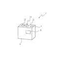
以下、図面を参照して本発明の実施の形態に係る投影装置について説明する。図1は、この実施の形態に係る投影装置としてのプロジェクタ2の外観を示す斜視図である。図1に示すように、プロジェクタ2は、金属やプラスチックからなる筐体4を備え、筐体4の前面6には、筐体4に内蔵された投影ユニット80(図4参照)の投影窓8が設けられている。また、プロジェクタ2の上面10には、電源スイッチ12や各種機能の設定を行うための操作部14が設けられている。なお、筐体4の側面には各種入力端子や冷却風の通気口等(不図示)が設けられている。
Hereinafter, a projection apparatus according to an embodiment of the present invention will be described with reference to the drawings. FIG. 1 is a perspective view showing an appearance of a
図2は、プロジェクタ2により画像の投影を行っているときの第1の状態を示す斜視図である。図2に示すように、プロジェクタ2は、筐体4の上面10に対向する面である下面が水平面Gに接するように直立して設置されている。また、筐体4の前面に設けられた投影窓から、投射光が斜め下方に投射され、水平面G上に投影画像Pが投影されている。なお、水平面Gは机の表面等の水平あるいは略水平な面である。
FIG. 2 is a perspective view showing a first state when the
ここで、筐体4の下面は、筐体4を設置するときに使用する設置面として機能すると共に、筐体4の前面6に設けられた投影窓8から、投影画像Pの投影面である水平面Gまでの距離を規定する距離基準面としても機能する。即ち、筐体4が下面を下にして水平面G上に設置されることにより、筐体4の正面6に設けられた投影窓8から載置面Gまでの距離が一義的に決定される。また、このとき、距離基準面としての筐体4の下面と、投影画像Pが投影される投影面としての水平面Gとは互いに平行になっている。このようにして、プロジェクタ2による画像の投影距離が一義的に決定されることにより、後述する投影ユニット80内の光学部材は、当該投影距離だけ離れた位置において鮮明な投影画像を結像できるように、投影ユニット80内において所定の位置にあらかじめ固定されている。
Here, the lower surface of the
図3は、この実施の形態に係る投影装置としてのプロジェクタ2により画像の投影を行っているときの第2の状態を示す斜視図である。図3に示すように、プロジェクタ2は、筐体4の前面6に対向する面である後面が水平面Gに接すると共に、下面が水平面Gに垂直な面である壁面Hに接するようにして設置されている。また、筐体4の前面に設けられた投影窓から、投射光が斜め上方に投射され、壁面H上に投影画像Pが投影されている。
FIG. 3 is a perspective view showing a second state when an image is projected by the
ここで、筐体4の後面は、筐体4を設置するときに使用する設置面として機能しており、下面は、筐体4の前面6に設けられた投影窓8から、投影画像Pの投影面である壁面Hまでの距離を規定する距離基準面として機能する。即ち、筐体4が後面を下にして水平面G上に設置されると共に、下面が壁面Hに接するようにして設置されることにより、筐体4の正面6に設けられた投影窓8から壁面Hまでの距離が一義的に決定される。また、このとき、距離基準面としての筐体4の下面と、投影画像Pが投影される投影面としての壁面Hとは互いに平行になっている。このように、筐体4を水平面G上に設置して画像を壁面H上に投影する場合にも、画像の投影距離が一義的に決定される。
Here, the rear surface of the
図4は、この実施の形態に係るプロジェクタ2が備える投影ユニット80の内部の構成を示す断面図である。ここで、投影ユニット80は、投影レンズ群90及びミラー92を含む斜め投射系のユニットである。なお、図4は、投影ユニット80の前方、即ちプロジェクタ2の筐体4の前面側から見た断面図である。投影光を発光する光源としてのLED82から射出された投影光は、集光レンズ群84によって平行光に変換された後にPBS(偏光ビームスプリッタ)86に入射し、入射光の進行方向に対して45°の角度で設けられた偏光分離膜86aに照射される。照射された投影光のうち、S偏光のみが偏光分離膜86aによって反射され、PBS86の下面から下方に向かって射出された後に、PBS86の下方に設置された画像表示部としてのノーマリブラックタイプのLCOS(反射型液晶素子)88に入射する。一方、偏光分離膜86aを透過したP偏光は、黒色処理等の無反射処理が施されたPBS86の側面に入射して吸収される。
FIG. 4 is a cross-sectional view showing the internal configuration of the
LCOS88に入射した光は、LCOS88により反射され、PBS86に再度入射する。ここで、LCOS88を構成する図示しない液晶層は、電圧が印加されると入射光に対して位相板として機能する。従って、LCOS88から射出する光のうち、液晶層により電圧が印加された画素領域を透過した光はS偏光からP偏光に変換される。一方、LCOS88から射出する光のうち、液晶層により電圧が印加されていない画素領域を透過した光はS偏光のまま進行する。
The light incident on the LCOS 88 is reflected by the LCOS 88 and enters the PBS 86 again. Here, a liquid crystal layer (not shown) constituting the
LCOS88から射出してPBS86に再度入射した光のうち、LCOS88の電圧が印加された画素領域を透過したP偏光のみが偏光分離膜86aを透過し、S偏光と分離される。当該P偏光は、PBS86から上方へ向かって射出された後に、投影用光学像を投影するための投影レンズ群90、及び投影レンズ群90から射出された光学像の投影方向を偏向させるためのミラー92を介して投影ユニット80から射出されて、プロジェクタ2の筐体4の前面6に設けられた投影窓8を介して投影される。
Of the light emitted from the
ここで、ミラー92は、投影面に投影される投影画像Pに対して台形補正を施すことができるように、所定の曲率を有する曲面ミラーから構成されている。また、投影ユニット80内の投影光学系を構成するすべての光学部材は、投影ユニット80に対して固定されている。上述のように、この実施の形態に係るプロジェクタ2においては、プロジェクタ2を水平面G上に設置したときに画像の投影距離が一義的に定まるため、当該投影距離だけ離れた位置において鮮明な投影画像を結像できるように、投影ユニット80内の光学部材を所定の位置にあらかじめ固定しておくことができる。
Here, the
次に、図5を用いてこの実施の形態に係る投影装置による投影画像サイズの拡大縮小処理について説明する。図5は、プロジェクタ2よって投影されている画像に拡大縮小処理が実行されているときの状態を示す図である。図5に示すように、投影面G上に投影されている投影画像Pが拡大または縮小される場合には、投影画像Pの筐体4にもっとも近い一辺が固定されて行われる。このようにして画像の拡大縮小が行われることにより、必要とされる画像の投影領域を最小にすることができる。即ち、このプロジェクタ2によれば、机の表面等の画像の投影領域が比較的狭い面に画像を投影する場合が多いため、このようにして投影画像Pの拡大縮小を行うことにより、むやみに画像の投影領域が拡大することを防止できる。また、拡大縮小の基準となる位置を使用者が容易に認識することができるため使用者にとっても扱いやすくなる。
Next, a projection image size enlargement / reduction process performed by the projection apparatus according to this embodiment will be described with reference to FIG. FIG. 5 is a diagram showing a state when the enlargement / reduction process is being performed on the image projected by the
ここで、投影画像Pの拡大縮小は、投影ユニット80のLCOS88上に表示される画像が、投影画像Pの上述の一辺に対応する一辺が固定された状態で、縦横比を保ちながら拡大縮小されることによって行われる。投影ユニット80内に収容されている光学部材はすべて投影ユニット80に対して固定されているため、このような電気的制御によって投影画像Pの拡大縮小が行われる。
Here, the projection image P is enlarged or reduced while maintaining the aspect ratio of the image displayed on the
なお、この発明の実施の形態に係るプロジェクタ2は、投影ユニット80に替えて、図6に示す他の投影ユニット180を備えていてもよい。この投影ユニット180は、ユニット内に画像表示部として透過型の液晶ディスプレイを備えているが、この点以外は投影ユニット80と同様の構成を備えている。従って、投影ユニット180の説明においては、投影ユニット80と同一の構成については説明を省略する。また、投影ユニット180の説明においては、投影ユニット80と同一の構成には同一の符号を付して行なう。
Note that the
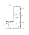
図6は、投影ユニット180の内部の構成を示す断面図である。なお、図6は、投影ユニット180を横方向、即ちプロジェクタ2の筐体4の側面側から見たときの断面図である。図6に示すように、矩形状の断面を有するユニット180には、下方からLED82、集光レンズ群84、投影光のP偏光成分のみを透過する第1偏光板182、画像表示素子としてのLCD(透過型の液晶ディスプレイ)184、投影光のS偏光成分のみを透過する第2偏光板186、投影レンズ群90、及びミラー92が配置されている。
FIG. 6 is a cross-sectional view showing an internal configuration of the
LED82から上方へ発光され、集光レンズ群84により平行光に変換された無偏光である投影光は、第1偏光板182によってP偏光の直線偏光に変換された後に、LCD184に入射する。ここで、LCD184を構成する画素領域の中で、電圧が印加されていない画素領域を透過した光はP偏光からS偏光に変換される。一方、電圧が印加された画素領域を透過した光は偏光特性に変化が生じず、P偏光のまま射出される。P偏光とS偏光の混合光となってLCD184から射出された投影光は、S偏光のみが第2偏光板186を透過して投影レンズ群90に入射する。投影レンズ群90から射出された投影光は、曲面ミラーから構成されたミラー92に反射して投影方向が偏向されると共に、投影画像の台形補正が施されて投影ユニット180の投影窓188から投射される。
Non-polarized projection light emitted upward from the
なお、上述の投影ユニット80と同様に、投影ユニット180内の投影光学系を構成するすべての光学部材も、投影ユニット180に対して固定されている。上述のように、この実施の形態に係るプロジェクタ2においては、プロジェクタ2を水平面G上に設置したときに画像の投影距離が一義的に定まるため、当該投影距離だけ離れた位置において鮮明な投影画像を結像できるように、投影ユニット180内の光学部材を所定の位置にあらかじめ固定しておくことができる。
Note that, similarly to the
この実施の形態に係る投影装置によれば、筐体が備える設置面を使用して水平面上に設置することにより、筐体が備える投影窓から画像を投影する投影面までの距離が一義的に決定されるため、投影ユニットが備える光学系の光学部材を、投影ユニットに対してすべて固定して配置することができる。従って、フォーカス調整用の機構等を設ける必要がなく、投影ユニット、ひいては投影装置の機構を単純化して、軽量化、小型化、コスト削減等を実現することができる。また、可動部が存在しないため、投影光学系の精度低下を防止して信頼性を向上させることができると共に、装置の使用時にフォーカス調整等の操作をすることなく鮮明な画像を投影することができるため、操作性が格段に向上する。 According to the projection apparatus according to this embodiment, the distance from the projection window provided in the housing to the projection surface for projecting the image is uniquely determined by using the installation surface provided in the housing on the horizontal plane. Therefore, all the optical members of the optical system included in the projection unit can be fixedly arranged with respect to the projection unit. Therefore, it is not necessary to provide a focus adjustment mechanism or the like, and it is possible to simplify the projection unit, and thus the mechanism of the projection apparatus, to achieve weight reduction, size reduction, cost reduction, and the like. In addition, since there are no moving parts, the accuracy of the projection optical system can be prevented and reliability can be improved, and a clear image can be projected without performing operations such as focus adjustment when the apparatus is used. Therefore, the operability is greatly improved.
また、この実施の形態に係る投影装置によれば、投影ユニットが、投影された画像に対して、投影装置の筐体に近い1辺を固定して拡大縮小処理を行うため、投影画像のサイズを容易に変更することができると共に、必要とされる画像の投影領域を最小にすることができる。 In addition, according to the projection apparatus according to this embodiment, the projection unit performs enlargement / reduction processing on the projected image by fixing one side close to the casing of the projection apparatus. Can be easily changed, and the required projection area of the image can be minimized.
以上より、この実施の形態に係る投影装置によれば、種々の調整を必要とせず、容易な操作で画像を投影することができる。 As described above, according to the projection device according to this embodiment, it is possible to project an image with an easy operation without requiring various adjustments.
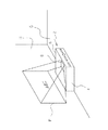
次に、図面を参照して本発明の実施の形態に係る第2の投影装置について説明する。図7は、この実施の形態に係る第2の投影装置としてのプロジェクタ102の概略構成を示すブロック図であり、図8は、プロジェクタ102により画像の投影を行っているときの状態を示す斜視図である。図7に示すように、プロジェクタ102は、各部の機能を統括的に制御する制御部104と、上述のプロジェクタ2が備える投影ユニット80と同一の構成を有する投影ユニット106とを備えると共に、プロジェクタ102の筐体120の正面に設けられた撮像窓122(図8参照)を介して入射する光を撮像する撮像ユニット108を備えている。また、プロジェクタ102は、撮像ユニット108において撮像された画像に基づいて画像を投影する投影領域を決定する投影領域決定部110を備えている。
Next, a second projection apparatus according to an embodiment of the present invention will be described with reference to the drawings. FIG. 7 is a block diagram showing a schematic configuration of the
図8に示すように、撮像ユニット108は、筐体120の正面に設けられた撮像窓122から、投影ユニット106によって投影される投影画像の投影領域を含めた前方領域Fを撮像する。投影領域決定部110は、撮像された画像に基づいて画像を投影する投影領域を決定する。例えば、図8に示すように、プロジェクタ102が机の表面上に設置されており、投影領域が机の形状(端部)によって制限される場合には、投影領域決定部110は、筐体120の前方領域Fを撮像した撮像画像に基づいて、投影画像Pの投影領域が机の表面から逸脱しないように投影領域を決定する。
As illustrated in FIG. 8, the
投影領域が決定されると、制御部104は、投影ユニット106に対して制御信号を送信し、当該投影領域内に収まるように投影画像Pを投影するように指示する。即ち、投影ユニット106は、LCOS88に表示される画像を適切なサイズで表示し、当該投影領域に収まるよう電気的に画像サイズを制御する。なお、以上のような画像サイズの決定処理は、投影画像Pの投影の前に行ってもよいし、投影画像Pの投影と同時、即ち、図8に示すように、図中の点線で示す始めに投影された投影画像Pのサイズを実線で示す補正後のサイズに変更するような処理を行ってもよい。
When the projection area is determined, the
この実施の形態に係る投影装置によれば、投影面を撮像する撮像ユニットと、撮像ユニットにより撮像された投影面の撮像画像を用いて、投影ユニットにより画像を投影することのできる投影領域を決定する投影領域決定部とを備え、投影ユニットが、決定された投影領域内に画像の投影を行うため、机の表面等の投影領域が制限された投影面に対して最適化された画像サイズで投影画像の投影を行うことができる。 According to the projection apparatus according to this embodiment, a projection area in which an image can be projected by the projection unit is determined using an imaging unit that images the projection plane and a captured image of the projection plane captured by the imaging unit. A projection area determining unit for projecting an image within the determined projection area, so that the projection size is optimized for a projection surface with a limited projection area such as a desk surface. Projection images can be projected.
次に、図面を参照して本発明の実施の形態に係る第3の投影装置について説明する。図9は、この実施の形態に係る第3の投影装置としてのプロジェクタ202により画像の投影を行っているときの第1の状態を示す斜視図である。図9に示すように、プロジェクタ202は、金属やプラスチックからなる筐体204を備え、筐体204の上部には、電源スイッチや各種機能の設定を行うための操作部等が設けられた上面206と、上方に向かって開閉自在に設けられたカバー208とが設けられている。プロジェクタ202の使用時に、自動または手動によってカバー208を回転軸210回りに所定の角度だけ回転させることによって開放させ、カバー208の下方側に設置されたミラー212を露出させる。なお、当該角度は予め決定された角度であって変更されるものではない。カバー208が開放されると、筐体204の第2の上面214の中央に設けられた投影窓216が露出する。プロジェクタ202は、筐体204の内部に図示しない投影ユニットを有しており、当該投影ユニットから投影される投影画像Pは、投影窓216を透過後にミラー212において反射し、筐体204が設置されている水平面G上に投影される。
Next, a third projection apparatus according to an embodiment of the present invention will be described with reference to the drawings. FIG. 9 is a perspective view showing a first state when an image is projected by the
プロジェクタ202は、筐体204の上面206に対向する面である下面が、水平面Gに接するようにして水平面G上に設置されている。ここで、当該下面は、筐体204を設置するときに使用する設置面として機能すると共に、筐体204の投影窓216から、投影画像Pの投影面である水平面Gまでの距離を規定する距離基準面としても機能する。即ち、筐体204が下面を下にして水平面G上に設置されることにより、筐体204の投影窓216から水平面Gまでの距離が一義的に決定される。また、このとき、距離基準面としての筐体204の下面と、投影画像Pが投影される投影面としての水平面Gとは互いに平行になっている。このようにして、プロジェクタ202による画像の投影距離が一義的に決定されることにより、筐体204内に収容された上述の投影ユニットの光学部材は、当該投影距離だけ離れた位置において鮮明な投影画像を結像できるように、当該投影ユニット内において所定の位置にあらかじめ固定される。
The
図10は、この実施の形態に係る投影装置としてのプロジェクタ202により画像の投影を行っているときの第2の状態を示す斜視図である。図10に示すように、プロジェクタ202は、筐体204の後面が水平面Gに、下面が水平面Gに垂直な面である壁面Hに接するようにして設置されている。また、筐体204に設けられた投影窓216から投射された投影画像Pは、筐体204のカバー208に設けられたミラー212(図10において不図示)において反射した後に壁面H上に投影されている。
FIG. 10 is a perspective view showing a second state when an image is projected by the
ここで、筐体204の後面は、筐体204を設置するときに使用する設置面として機能しており、下面は、筐体204の投影窓216から、画像の投影面である壁面Hまでの距離を規定する距離基準面として機能している。即ち、筐体204が後面を下にして水平面G上に設置されると共に、下面が壁面Hに接するようにして設置されることにより、筐体204に設けられた投影窓216から壁面Hまでの距離が一義的に決定される。また、このとき、距離基準面としての筐体204の下面と、画像が投影される投影面としての壁面Hとは互いに平行になっている。このように、筐体204を水平面G上に設置して画像を壁面H上に投影する場合にも、画像の投影距離が一義的に決定される。
Here, the rear surface of the
この実施の形態に係る投影装置によれば、種々の調整を必要とせず、容易な操作で画像を投影することができる。 According to the projection apparatus according to this embodiment, it is possible to project an image with an easy operation without requiring various adjustments.
なお、上述の各実施の形態に係る投影ユニットにおいては、所定の曲率を有する曲面ミラーから構成されており、かつ図6に示すような凹面形状の反射面を有するミラー92を備えているが、ミラー92に代えて、自由曲面ミラーから構成され、かつ凹面形状の反射面を有するミラーを備えるようにしてもよい。
The projection unit according to each of the above-described embodiments includes a
また、ミラー92に代えて、自由曲面ミラーから構成され、かつ図11に示すような凸面形状の反射面を有するミラー100を備えるようにしてもよい。この凸面ミラー100を備えた場合には、中間像を形成する必要のある凹面ミラー92を備える場合と比較して、中間像形成のための機構等を設ける必要がなく、投影ユニット、ひいては投影装置の軽量化、小型化、コスト削減等を実現することができる。
Moreover, it may replace with the
また、投影ユニット内の投影光学系を構成する光学部材の少なくとも一面が自由曲面により構成されていてもよい。この場合には、投影ユニット内の投影光学系を構成するすべての光学部材が投影ユニットに対して固定されているため、自由曲面を有する光学部材の精度低下を防止することができ、容易に歪曲のない投影画像を形成することができる。 Further, at least one surface of the optical member constituting the projection optical system in the projection unit may be configured by a free curved surface. In this case, since all the optical members constituting the projection optical system in the projection unit are fixed with respect to the projection unit, it is possible to prevent a decrease in accuracy of the optical member having a free-form surface and to easily distort the optical member. It is possible to form a projection image without any image.
2,102,202…プロジェクタ、4,120,204…筐体、8,216…投影窓、
80,180…投影ユニット、122…撮像窓、212…ミラー、F…前方領域、G…水
平面、H…壁面、P…投影画像
2, 102, 202 ... projector, 4, 120, 204 ... housing, 8, 216 ... projection window,
80, 180 ... projection unit, 122 ... imaging window, 212 ... mirror, F ... front region, G ... horizontal plane, H ... wall surface, P ... projected image
Claims (4)
前記投影ユニットを収容する筐体と、
前記画像を投影する投影面を撮像する撮像ユニットと、
前記撮像ユニットにより撮像された前記投影面の撮像画像を用いて、前記投影ユニットにより前記画像を投影することのできる投影領域を決定する投影領域決定部とを備え、
前記筐体を設置するとき設置面として使用される前記筐体の面と、前記投影面とは平行であり、
前記投影ユニットは、
前記投影面に投影された画像に対して、前記投影ユニットによって前記投影面に前記画像を投影可能な範囲のうちの最も前記筐体に近い前記投影可能な範囲の一辺を固定して、画像信号を処理することにより拡大縮小処理を行い、前記投影領域内に前記画像を投影することを特徴とする投影装置。 A projection unit comprising an optical system for projecting an image;
A housing that houses the projection unit ;
An imaging unit for imaging a projection plane for projecting the image;
A projection region determining unit that determines a projection region in which the projection unit can project the image using the captured image of the projection surface captured by the imaging unit;
The plane of the casing used as an installation surface when installing the casing and the projection plane are parallel,
The projection unit is
For the image projected on the projection plane, one side of the projectable range closest to the housing among the range capable of projecting the image onto the projection plane by the projection unit is fixed, and an image signal There row scaling processing by processing the projection apparatus characterized by projecting the image on the projection area.
前記筐体が備える投影窓から前記画像を投影する投影面までの距離を規定する距離基準面及び前記筐体を設置するときに使用する第1の設置面として機能する前記筐体に設けられた第1の面と、
前記第1の面と直交し、前記筐体を設置するときに使用する第2の設置面として機能する前記筐体に設けられた第2の面とを備えることを特徴とする請求項1または2記載の投影装置。 The housing is
Provided in the casing that functions as a distance reference plane that defines a distance from a projection window provided in the casing to a projection plane that projects the image, and a first installation plane that is used when the casing is installed. The first aspect;
Perpendicular to the first surface, the claims, characterized in that it comprises a second surface provided in the housing which serves as a second mounting surface to be used when installing the housing 1 or The projection apparatus according to 2 .
前記画像を投影している状態において、前記投影ユニットに対してすべて固定されていることを特徴とする請求項1〜3の何れか一項に記載の投影装置。 The optical member constituting the optical system is
In the state that projecting the image projection apparatus according to any one of claim 1 to 3, characterized in that it is all fixed relative to the projection unit.
Priority Applications (5)
| Application Number | Priority Date | Filing Date | Title |
|---|---|---|---|
| JP2009258490A JP5446753B2 (en) | 2008-12-10 | 2009-11-12 | Projection device |
| CN2012102907940A CN102866566A (en) | 2008-12-10 | 2009-11-13 | Projection apparatus |
| US13/133,497 US8911096B2 (en) | 2008-12-10 | 2009-11-13 | Projection apparatus for projecting and processing an image |
| CN200980146560.5A CN102224455B (en) | 2008-12-10 | 2009-11-13 | Projection device |
| PCT/JP2009/069312 WO2010067688A1 (en) | 2008-12-10 | 2009-11-13 | Projection device |
Applications Claiming Priority (3)
| Application Number | Priority Date | Filing Date | Title |
|---|---|---|---|
| JP2008314198 | 2008-12-10 | ||
| JP2008314198 | 2008-12-10 | ||
| JP2009258490A JP5446753B2 (en) | 2008-12-10 | 2009-11-12 | Projection device |
Publications (3)
| Publication Number | Publication Date |
|---|---|
| JP2010160476A JP2010160476A (en) | 2010-07-22 |
| JP2010160476A5 JP2010160476A5 (en) | 2012-11-29 |
| JP5446753B2 true JP5446753B2 (en) | 2014-03-19 |
Family
ID=42577645
Family Applications (1)
| Application Number | Title | Priority Date | Filing Date |
|---|---|---|---|
| JP2009258490A Expired - Fee Related JP5446753B2 (en) | 2008-12-10 | 2009-11-12 | Projection device |
Country Status (1)
| Country | Link |
|---|---|
| JP (1) | JP5446753B2 (en) |
Families Citing this family (7)
| Publication number | Priority date | Publication date | Assignee | Title |
|---|---|---|---|---|
| JP5381377B2 (en) | 2009-06-18 | 2014-01-08 | セイコーエプソン株式会社 | projector |
| JP5754124B2 (en) * | 2010-12-14 | 2015-07-29 | セイコーエプソン株式会社 | Projector and control method |
| JP5686256B2 (en) * | 2011-08-30 | 2015-03-18 | 株式会社リコー | Projector device |
| JP5637459B2 (en) * | 2012-06-11 | 2014-12-10 | 株式会社リコー | Projection optical device and image projection device |
| JP2014153478A (en) | 2013-02-06 | 2014-08-25 | Sony Corp | Image projection apparatus and image projection method |
| JP6191905B2 (en) * | 2013-03-08 | 2017-09-06 | 株式会社リコー | Projection optical device and image projection device |
| JP5626436B2 (en) * | 2013-10-02 | 2014-11-19 | セイコーエプソン株式会社 | projector |
Family Cites Families (4)
| Publication number | Priority date | Publication date | Assignee | Title |
|---|---|---|---|---|
| JP3960390B2 (en) * | 2004-05-31 | 2007-08-15 | Necディスプレイソリューションズ株式会社 | Projector with trapezoidal distortion correction device |
| JP4720595B2 (en) * | 2006-04-21 | 2011-07-13 | カシオ計算機株式会社 | Projector, video projection method and program |
| JP2007322811A (en) * | 2006-06-01 | 2007-12-13 | Hitachi Ltd | Projection optical unit and projection type video display apparatus |
| JP4901595B2 (en) * | 2007-03-06 | 2012-03-21 | 三洋電機株式会社 | Projection display |
-
2009
- 2009-11-12 JP JP2009258490A patent/JP5446753B2/en not_active Expired - Fee Related
Also Published As
| Publication number | Publication date |
|---|---|
| JP2010160476A (en) | 2010-07-22 |
Similar Documents
| Publication | Publication Date | Title |
|---|---|---|
| JP5446753B2 (en) | Projection device | |
| US8911096B2 (en) | Projection apparatus for projecting and processing an image | |
| US8226248B2 (en) | Projection display device with shift mechanism for displacing an imager | |
| JP2003029339A (en) | Rear projection optical system | |
| CN101261358A (en) | Projection display device | |
| JP5002319B2 (en) | Projection display | |
| JP5407170B2 (en) | Projector and projection system | |
| JP4500889B2 (en) | Electronic viewfinder device, imaging device | |
| JP2015059968A (en) | Image display device | |
| US20110210945A1 (en) | Projector | |
| JP2005017336A (en) | Projector having projection surface distance measuring device | |
| JP2003207740A (en) | Video light generation optical unit and back projection type video display | |
| JP2010122585A (en) | Projector | |
| JP2013171152A (en) | Image projection device | |
| JP5526838B2 (en) | projector | |
| JP5444947B2 (en) | projector | |
| WO2010067688A1 (en) | Projection device | |
| JP4957085B2 (en) | Projection optical system and projector | |
| JP4827872B2 (en) | Projection display device | |
| JP5434060B2 (en) | projector | |
| JP2009206726A (en) | Projection video display device | |
| JP2011048039A (en) | Projector | |
| JP5262475B2 (en) | Imaging device | |
| JP2007328086A (en) | Projection optical system and projector | |
| JP2011186097A (en) | Projector |
Legal Events
| Date | Code | Title | Description |
|---|---|---|---|
| A621 | Written request for application examination |
Free format text: JAPANESE INTERMEDIATE CODE: A621 Effective date: 20121005 |
|
| A521 | Request for written amendment filed |
Free format text: JAPANESE INTERMEDIATE CODE: A523 Effective date: 20121012 |
|
| A131 | Notification of reasons for refusal |
Free format text: JAPANESE INTERMEDIATE CODE: A131 Effective date: 20130625 |
|
| A521 | Request for written amendment filed |
Free format text: JAPANESE INTERMEDIATE CODE: A523 Effective date: 20130826 |
|
| TRDD | Decision of grant or rejection written | ||
| A01 | Written decision to grant a patent or to grant a registration (utility model) |
Free format text: JAPANESE INTERMEDIATE CODE: A01 Effective date: 20131203 |
|
| A61 | First payment of annual fees (during grant procedure) |
Free format text: JAPANESE INTERMEDIATE CODE: A61 Effective date: 20131216 |
|
| R150 | Certificate of patent or registration of utility model |
Ref document number: 5446753 Country of ref document: JP Free format text: JAPANESE INTERMEDIATE CODE: R150 Free format text: JAPANESE INTERMEDIATE CODE: R150 |
|
| R250 | Receipt of annual fees |
Free format text: JAPANESE INTERMEDIATE CODE: R250 |
|
| R250 | Receipt of annual fees |
Free format text: JAPANESE INTERMEDIATE CODE: R250 |
|
| R250 | Receipt of annual fees |
Free format text: JAPANESE INTERMEDIATE CODE: R250 |
|
| R250 | Receipt of annual fees |
Free format text: JAPANESE INTERMEDIATE CODE: R250 |
|
| R250 | Receipt of annual fees |
Free format text: JAPANESE INTERMEDIATE CODE: R250 |
|
| LAPS | Cancellation because of no payment of annual fees |