JP5444564B2 - Coin size display device for coin hopper - Google Patents
Coin size display device for coin hopper Download PDFInfo
- Publication number
- JP5444564B2 JP5444564B2 JP2009257746A JP2009257746A JP5444564B2 JP 5444564 B2 JP5444564 B2 JP 5444564B2 JP 2009257746 A JP2009257746 A JP 2009257746A JP 2009257746 A JP2009257746 A JP 2009257746A JP 5444564 B2 JP5444564 B2 JP 5444564B2
- Authority
- JP
- Japan
- Prior art keywords
- guide
- coin
- hole
- display
- outlet
- Prior art date
- Legal status (The legal status is an assumption and is not a legal conclusion. Google has not performed a legal analysis and makes no representation as to the accuracy of the status listed.)
- Active
Links
- 238000001514 detection method Methods 0.000 description 20
- 230000002093 peripheral effect Effects 0.000 description 16
- 239000002184 metal Substances 0.000 description 13
- 239000008186 active pharmaceutical agent Substances 0.000 description 9
- 238000007796 conventional method Methods 0.000 description 4
- 238000000605 extraction Methods 0.000 description 4
- 230000002159 abnormal effect Effects 0.000 description 3
- 238000000034 method Methods 0.000 description 3
- 239000011347 resin Substances 0.000 description 3
- 229920005989 resin Polymers 0.000 description 3
- 239000003638 chemical reducing agent Substances 0.000 description 2
- 230000005611 electricity Effects 0.000 description 2
- 230000003068 static effect Effects 0.000 description 2
- 230000005856 abnormality Effects 0.000 description 1
- 230000002411 adverse Effects 0.000 description 1
- 238000010586 diagram Methods 0.000 description 1
- 230000005484 gravity Effects 0.000 description 1
- 238000003780 insertion Methods 0.000 description 1
- 230000037431 insertion Effects 0.000 description 1
- 230000000149 penetrating effect Effects 0.000 description 1
- 229910001220 stainless steel Inorganic materials 0.000 description 1
- 239000010935 stainless steel Substances 0.000 description 1
- 238000003756 stirring Methods 0.000 description 1
Images


Description
本発明は、固定ガイドと、弾性的に付勢力を与えられた可動ガイドとによってコインを挟んで一つずつ出口通路に弾き出した後、出口通路の端部の出口から払い出すコインホッパに関する。
詳細には、前記弾き出されるコインのサイズが間違いなく表示されるようにしたコインホッパのコインサイズ表示装置に関する。
さらに詳細には、前記弾き出されるコインのサイズを決定するコインガイドの設定状態によって自動的にコインサイズが表示されるようにしたコインホッパのコインサイズ表示装置に関する。
本明細書において、コインとは、通貨としてのコインの他、ゲーム用のトークン等をも含んでいる。
The present invention relates to a coin hopper that is ejected from an exit at an end of an exit passage after the coins are flipped out one by one by a fixed guide and a movable guide that is elastically biased.
Specifically, the present invention relates to a coin size display device for a coin hopper in which the size of the coin to be flipped out is definitely displayed.
More specifically, the present invention relates to a coin size display device for a coin hopper that automatically displays a coin size according to a setting state of a coin guide that determines the size of the coin to be ejected.
In this specification, the coin includes not only a coin as a currency but also a token for a game.
第1の従来技術として、コインホッパから払い出されるコインの金種を目視可能にするため、コインホッパの筐体に金種を表示したシールを貼付することが行われている(例えば、特許文献1参照)。
第2の従来技術として、パチスロに用いられるコインホッパにおいては、2種類のメダルサイズに選択的に容易に適応できるようにするものが知られている(例えば、特許文献2参照)。
As a first conventional technique, in order to make it possible to visually check the denomination of a coin paid out from a coin hopper, a sticker displaying the denomination is attached to a casing of the coin hopper (see, for example, Patent Document 1). .
As a second conventional technique, a coin hopper used for a pachi-slot is known that can be easily and selectively adapted to two types of medal sizes (see, for example, Patent Document 2).
第1の従来技術において、コインホッパから払い出すコインの金種を変更した場合、金種シールを張り替える必要があり煩雑であるという問題がある。
第2の従来技術において異なるメダルサイズに変更する場合、メダル出口を構成するメダルガイドを反転させることにより行う。
メダルサイズを変更した場合、どのサイズに適合しているかを表示する必要があるが、第2の従来技術には何ら開示が無いため、第1の従来技術のようにシールを貼付する方法で行うと解され、第1の従来技術同様に煩雑である問題がある。
In the first conventional technique, when the denomination of the coin paid out from the coin hopper is changed, there is a problem that it is necessary to replace the denomination seal, which is complicated.
When changing to a different medal size in the second conventional technique, the medal guide constituting the medal exit is reversed.
When the medal size is changed, it is necessary to display which size is suitable, but since there is no disclosure in the second prior art, it is performed by a method of sticking a seal as in the first prior art. There is a problem that is complicated as in the first prior art.
本発明の第1の目的は、使用するコインサイズを変更した場合、容易かつ間違いなく使用可能なコインサイズを表示可能にするコインホッパのコインサイズ表示装置を提供することである。
本発明の第2の目的は、コインホッパの出口通路を画定するコインのガイド位置を変更した場合、当該コインガイドの位置変更に関連して使用可能なコインサイズが表示されるようにしたコインホッパのコインサイズ表示装置を提供することである。
本発明の第3の目的は、使用可能なコインサイズが間違いなく表示されるようにしたコインホッパのコインサイズ表示装置を提供することである。
本発明の第4の目的は、コインガイドとコインサイズ表示体とが一体的に固定されるようにすることにより、容易に固定及び取り外し出来るコインホッパのコインサイズ表示装置を提供することである。
A first object of the present invention is to provide a coin size display device for a coin hopper that can easily and definitely display usable coin sizes when the coin size to be used is changed.
The second object of the present invention is to display a coin size that can be used in association with the coin guide position change when the coin guide position defining the coin exit path is changed. A size display device is provided.
A third object of the present invention is to provide a coin size display device for a coin hopper in which usable coin sizes are definitely displayed.
A fourth object of the present invention is to provide a coin size display device of a coin hopper that can be easily fixed and removed by integrally fixing a coin guide and a coin size display body.
この目的を達成するため、本発明にかかるコインホッパのコインサイズ表示装置は以下のように構成される。
上部開口を有するコイン保留ボウルの底孔に配置された通孔付き回転ディスクによってコインを一枚ずつ区分けして、前記回転ディスクの側方に固定状態に配置した第1ガイド及び前記第1ガイドに対し弾性的に接離可能に設けられた第2ガイドによって構成された弾出装置によって出口通路に投出し、前記出口通路の端面の出口から投出するコインホッパにおいて、複数のガイド部を有するプレート状のガイド体の1のガイド部を選択的に前記第1ガイドとして構成することにより、前記第1ガイドの位置が使用対象のコイン直径に対応して設定され、前記複数のガイド部に対応した関連表示をする複数の表示部を有する表示手段と、前記ガイド体及び前記表示手段を一体的に固定する固定手段と、を含むコインサイズ表示装置を備え、前記固定手段は、前記ガイド体の選択された1のガイド部が前記第1ガイドに設定された場合、前記複数の表示部の内、当該選択されたガイド部に対応する表示部が前記出口に並置された場合にのみ前記ガイド体及び表示手段を一体的に固定可能であることを特徴とするコインホッパのコインサイズ表示装置である。
In order to achieve this object, a coin size display device for a coin hopper according to the present invention is configured as follows.
The coins are separated one by one by a rotating disk with a through hole disposed in the bottom hole of the coin holding bowl having an upper opening, and the first guide and the first guide are arranged in a fixed state on the side of the rotating disk. In a coin hopper that is thrown out to the exit passage by the ejecting device constituted by the second guide that is elastically attachable to and detachable from the end passage of the exit passage, a plate-like shape having a plurality of guide portions By selectively configuring one guide portion of the guide body as the first guide, the position of the first guide is set corresponding to the diameter of the coin to be used , and the relationship corresponding to the plurality of guide portions comprising a display means having a plurality of display unit for the display, the coin size display device including a fixing means for integrally fixing the guide body and the display unit, the fixed Stage, if the first guide unit selected of the guide body is set in the first guide, the plurality of display unit, a display unit corresponding to the selected guide portion is juxtaposed to said outlet a coin size display device of coin hopper, characterized in that be integrally fixing the guide body and the display unit only if.
本発明の第1の好ましい態様は、上部開口を有するコイン保留ボウルの底孔に配置された通孔付き回転ディスクによってコインを一枚ずつ区分けして、前記回転ディスクの下方に配置した底面上を滑らせて前記回転ディスクと共につれ回りさせて前記回転ディスクの側方に固定状態に配置した第1ガイド及び前記第1ガイドに対し弾性的に接離可能に設けられた第2ガイドによって構成された弾出装置に送り込み、前記弾出装置によって出口通路に投出し、前記出口通路の端面の出口から投出するコインホッパにおいて、前記第1ガイドは複数の角部を有するプレート状のガイド体の選択された角部によって構成され、前記ガイド体には仮位置決め用の1つのダボ孔が穿孔され、前記底面には前記ダボ孔に嵌り合うベースダボが突出形成され、さらに前記ガイド体には固定手段としてスクリュウのガイド貫通孔が形成され、横棒部と縦棒部とにより全体として大凡T形を呈する表示体を設け、当該表示体の横棒部の一端の第1端面及び他端の第2端面には前記ガイド体の複数の角部に対応する関連表示をする第1表示部及び第2表示部をそれぞれ設けると共に前記縦棒部に表示体貫通孔を設け、前記底面には前記固定用スクリュウのネジ孔が形成され、前記ガイド体の選択された第1角部により前記第1ガイドを構成し、かつ前記ベースダボが前記ダボ孔に嵌り合い、かつ前記表示体の第1表示部が前記出口に並置された場合、前記ネジ孔、ガイド貫通孔及び表示体貫通孔が同一軸線上に直列し、前記スクリュウによって前記プレート及び表示体を共締めにより固定可能とし、前記第2角部により前記第1ガイドを構成し、かつ前記ベースダボが前記ダボ孔に嵌り合い、かつ前記表示体の第2表示部が前記出口に並置された場合、前記ネジ孔、ガイド貫通孔及び表示体貫通孔が同一軸線上に直列し、前記スクリュウによって前記プレート及び表示体を共締めにより固定可能であることを特徴とするコインホッパのコインサイズ表示装置である。 According to a first preferred embodiment of the present invention, coins are separated one by one by a rotating disk with a through hole disposed in a bottom hole of a coin holding bowl having an upper opening, and a bottom surface disposed below the rotating disk is placed on the bottom surface. A first guide that is slid and swung together with the rotating disk and arranged in a fixed state on the side of the rotating disk, and a second guide that is elastically attached to and separated from the first guide. In the coin hopper that is fed into the ejecting device, thrown out into the exit passage by the ejecting device, and ejected from the exit of the end face of the exit passage, the first guide is selected as a plate-shaped guide body having a plurality of corners A dowel hole for temporary positioning is formed in the guide body, and a base dowel that fits into the dowel hole is formed on the bottom surface so as to protrude. The guide body is formed with a screw guide through hole as a fixing means, and is provided with a display body having a generally T shape as a whole by the horizontal bar portion and the vertical bar portion, and a first end of the horizontal bar portion of the display body is provided. On the end face and the second end face of the other end are provided a first display part and a second display part that perform a related display corresponding to a plurality of corners of the guide body, and a display body through hole is provided in the vertical bar part, A screw hole of the fixing screw is formed on the bottom surface, the first guide is constituted by the selected first corner portion of the guide body, the base dowel fits into the dowel hole, and the display body When the first display portion is juxtaposed at the outlet, the screw hole, the guide through hole, and the display body through hole are arranged in series on the same axis, and the plate and the display body can be fixed together by fastening with the screw. Front by the second corner Constitute a first guide, and the Besudabo is mutually fit into the dowel hole, and when the second display portion of the display body is juxtaposed to said outlet, said screw holes, guide holes, and the display body through holes same A coin size display device for a coin hopper, characterized in that the plate and the display body can be fixed together by being screwed in series on an axis.
本発明の第2の好ましい態様は、第2の好ましい例において、さらに前記出口通路の上側を画定する出口通路画定ガイドを設け、前記出口通路画定ガイドは下面に前記ダボ孔に嵌り合う出口通路画定ガイドダボ及びガイド貫通孔を有し、前記出口通路画定ガイドが正規の位置にセットされた場合前記ダボに嵌り合うと共に前記ガイド貫通孔が前記共通の軸線上に位置するよう設定されていることである。 According to a second preferred embodiment of the present invention, in the second preferred example, an outlet passage defining guide that further defines an upper side of the outlet passage is further provided, and the outlet passage defining guide is fitted to the dowel hole on a lower surface. A guide dowel and a guide through hole, and when the outlet passage defining guide is set at a normal position, the guide dowel fits the dowel and is set so that the guide through hole is located on the common axis. .
本発明において、保留ボウル内にバラ積みされたコインは、回転ディスクの回転によって通孔内に落下し、回転ディスクの裏面に形成された押動部によってベース上をスライドされ、第1ガイド及び第2ガイドによって構成される出口開口へ移動される。
出口開口に達したコインは、回転ディスクの押動部によって押進されることにより第2ガイドを弾き出し位置へ移動させる。
これにより、当該コインは、当該コインの中心を通る直線が第1ガイドと第2ガイドとの間を通過した直後に弾出装置によって出口通路に弾き出される。
弾き出されたコインは、出口通路に案内された後、出口から払い出される。
第1ガイドは、ガイド体の複数の角部によって構成され、当該複数の角部の1を選択して所定の位置に固定することにより、コイン直径に対応した位置に設定される。
この位置は、コイン直径に差があっても、第2ガイドの移動位置が一定になるよう設定されている。
ガイド体は表示体と共通の位置決め手段によって所定の位置に位置決めされ、その後固定手段によって固定される。
さらに、当該第1ガイドが弾出手段を構成した場合、表示体のうち第1ガイドに対応する表示部が出口の側方に位置し、また、第2ガイドが弾出手段を構成した場合、第2ガイドに対応する表示部が出口の側方に位置する。
これにより、コインの出口を正面に見た場合、その近傍の表示体の表示部を確認することにより適用可能なコインサイズを知ることができる。
In the present invention, the coins stacked in the storage bowl fall into the through hole by the rotation of the rotating disk, and are slid on the base by the pushing portion formed on the back surface of the rotating disk, and the first guide and the first guide It is moved to the outlet opening constituted by two guides.
The coin that has reached the outlet opening is pushed by the pushing portion of the rotating disk, thereby moving the second guide to the flip-out position.
Accordingly, the coin is ejected to the exit passage by the ejecting device immediately after the straight line passing through the center of the coin passes between the first guide and the second guide.
The coins ejected are guided to the exit passage and then paid out from the exit.
The first guide is constituted by a plurality of corner portions of the guide body, and is set at a position corresponding to the coin diameter by selecting one of the plurality of corner portions and fixing it to a predetermined position.
This position is set so that the movement position of the second guide is constant even if there is a difference in coin diameter.
The guide body is positioned at a predetermined position by positioning means common to the display body, and then fixed by fixing means.
Further, when the first guide constitutes the ejecting means, the display portion corresponding to the first guide of the display body is located on the side of the outlet, and when the second guide constitutes the ejecting means, A display unit corresponding to the second guide is located on the side of the exit.
Thereby, when the exit of the coin is viewed in front, the applicable coin size can be known by checking the display portion of the display body in the vicinity thereof.
第1の好ましい実施態様において、第1ガイドは複数の角部を有するプレート状のガイド体の選択された角部によって構成され、前記ガイド体には位置決め用の1つのダボ孔が穿孔され、前記底面には前記ダボ孔に嵌り合うベースダボが突出形成され、さらに前記ガイド体には位置決め手段及び固定手段としてスクリュウのガイド貫通孔が形成され、さらに横棒部と縦棒部とにより全体として大凡T形を呈する表示体を設け、当該表示体の横棒部の一端の第1端面及び他端の第2端面には前記ガイド体の複数の角部に対応する関連表示をする第1表示部及び第2表示部をそれぞれ設けると共に前記縦棒部に表示体貫通孔を設け、前記底面には前記固定用スクリュウのネジ孔が形成され、前記ガイド体の選択された第1角部により前記第1ガイドを構成し、かつ前記ベースダボが前記ダボ孔に嵌り合い、かつ前記表示体の第1表示部が前記出口に並置された場合、前記ネジ孔、ガイド貫通孔及び表示体貫通孔が同一軸線上に直列し、前記スクリュウによって前記ガイド体及び表示体を共締めにより位置決め及び固定可能とし、前記第2角部により前記第1ガイドを構成し、かつ前記ベースダボが前記ダボ孔に嵌り合い、かつ前記表示体の第2表示部が前記出口に並置された場合、前記ネジ孔、ガイド貫通孔及び表示体貫通孔が同一軸線上に重なり合うように直列し、前記スクリュウによって前記ガイド体及び表示体を共締めにより固定可能である。
要約すれば、スクリュウをガイド貫通孔及び表示体貫通孔を貫通させてネジ孔にねじ込むことにより、ガイド体及び表示体の位置決め及び固定ができる。
したがって、小型、かつ、安価に製造できると共に、対応するコインサイズへの変更作業が容易にできる利点がある。
In a first preferred embodiment, the first guide is constituted by a selected corner portion of a plate-shaped guide body having a plurality of corner portions, and the guide body is provided with one dowel hole for positioning, A base dowel that fits in the dowel hole is formed on the bottom, and a guide through hole for a screw is formed on the guide body as a positioning means and a fixing means. A display body having a shape, and a first display section for performing a related display corresponding to a plurality of corners of the guide body on a first end surface of one end and a second end surface of the other end of the horizontal bar portion of the display body; A second display portion is provided, a display body through hole is provided in the vertical bar portion, a screw hole of the fixing screw is formed on the bottom surface, and the first corner portion of the guide body is used to select the first display portion. Composing a guide When the base dowel fits into the dowel hole and the first display portion of the display body is juxtaposed to the outlet, the screw hole, the guide through hole, and the display body through hole are in series on the same axis, The guide body and the display body can be positioned and fixed together by the screw, the first corner is configured by the second corner portion, the base dowel fits into the dowel hole, and the
In summary, the guide body and the display body can be positioned and fixed by passing the screw through the guide through hole and the display body through hole and screwing the screw into the screw hole.
Therefore, there is an advantage that it can be manufactured in a small size and at a low cost, and the change operation to the corresponding coin size can be easily performed.
第2の好ましい態様は、第2の好ましい例において、さらに、前記出口通路の上側を画定する出口通路画定ガイドを設け、前記出口通路画定ガイドは下面に前記ダボ孔に嵌り合う出口通路画定ガイドダボ及びガイド貫通孔を有し、前記出口通路画定ガイドが正規の位置にセットされた場合、前記ダボに嵌り合うと共に前記ガイド貫通孔が前記共通の軸線上に位置するよう設定されている。
これにより、出口通路画定ガイドダボをダボ孔に嵌め込むことにより、出口通路画定ガイドは位置決めされ、さらに、ガイド貫通孔が前記共通の軸線上に重なるように位置するようになるので、スクリュウをネジ孔にねじ込むことができる。
したがって、コインサイズへの変更作業が容易にできる利点がある。
According to a second preferred embodiment, in the second preferred example, an outlet passage defining guide that further defines an upper side of the outlet passage is further provided, and the outlet passage defining guide is fitted to the dowel hole on a lower surface, and an outlet passage defining guide dowel and When the outlet passage defining guide is set at a normal position, the guide through hole is set so as to fit the dowel and be positioned on the common axis.
Thus, by fitting the outlet passage defining guide dowel into the dowel hole, the outlet passage defining guide is positioned, and the guide through hole is positioned so as to overlap the common axis. Can be screwed into.
Therefore, there is an advantage that it is possible to easily change the coin size.
本発明の最良の形態は、上部開口を有するコイン保留ボウルの底孔に配置された通孔付き回転ディスクによってコインを一枚ずつ区分けして、前記回転ディスクの下方に配置した底面上を滑らせて前記回転ディスクと共につれ回りさせて前記回転ディスクの側方に固定状態に配置した第1ガイド及び前記第1ガイドに対し弾性的に接離可能に設けられた第2ガイドによって構成された弾出装置に送り込み、前記弾出装置によって出口通路に投出し、前記出口通路の端面の出口から投出するコインホッパにおいて、前記第1ガイドは複数の角部を有するプレート状のガイド体の選択された角部によって構成され、前記ガイド体には位置決め用の1つのダボ孔が穿孔され、前記底面には前記ダボ孔に嵌り合うベースダボが突出形成され、さらに前記ガイド体には位置決め手段及び固定手段としてスクリュウのガイド貫通孔が形成され、さらに横棒部と縦棒部とにより全体として大凡T形を呈する表示体を設け、当該表示体の横棒部の一端の第1端面及び他端の第2端面には前記ガイド体の複数の角部に対応する関連表示をする第1表示部及び第2表示部をそれぞれ設けると共に前記縦棒部に表示体貫通孔を設け、前記底面には前記固定用スクリュウのネジ孔が形成され、前記ガイド体の選択された第1角部により前記第1ガイドを構成し、かつ前記ベースダボが前記ダボ孔に嵌り合い、かつ前記表示体の第1表示部が前記出口に並置された場合、前記ネジ孔、ガイド貫通孔及び表示体貫通孔が同一軸線上に直列し、前記スクリュウによって前記ガイド体及び表示体を共締めにより位置決め及び固定可能とし、前記第2角部により前記第1ガイドを構成し、かつ前記ベースダボが前記ダボ孔に嵌り合い、かつ前記表示体の第2表示部が前記出口に並置された場合、前記ネジ孔、ガイド貫通孔及び表示体貫通孔が同一軸線上に直列し、前記スクリュウによって前記ガイド体及び表示体を共締めにより固定可能であり、さらに前記出口通路の上側を画定する出口通路画定ガイドを設け、前記出口通路画定ガイドは下面に前記ダボ孔に嵌り合う出口通路画定ガイドダボ及びガイド貫通孔を有し、前記出口通路画定ガイドが正規の位置にセットされた場合前記ダボに嵌り合うと共に前記ガイド貫通孔が前記共通の軸線上に位置するよう設定されていることを特徴とするコインホッパのコインサイズ表示装置である。 The best mode of the present invention is to divide coins one by one by a rotating disk with a through hole disposed in the bottom hole of a coin holding bowl having an upper opening, and slide on the bottom surface disposed below the rotating disk. A first guide that is rotated together with the rotary disk and fixed in a side of the rotary disk, and a second guide that is elastically attached to and separated from the first guide. In a coin hopper that is fed into an apparatus, thrown into an outlet passage by the ejecting device, and thrown out from an outlet at an end surface of the outlet passage, the first guide is a selected corner of a plate-shaped guide body having a plurality of corners A dowel hole for positioning is formed in the guide body, a base dowel that fits into the dowel hole is formed on the bottom surface, and the guide body further protrudes. The guide body is formed with a screw guide through hole as a positioning means and a fixing means, and further provided with a display body having a general T shape by a horizontal bar portion and a vertical bar portion, and one end of the horizontal bar portion of the display body. The first end surface and the second end surface of the other end are provided with a first display portion and a second display portion, respectively, for displaying related information corresponding to a plurality of corner portions of the guide body, and the vertical bar portion has a display body through hole. A screw hole of the fixing screw is formed on the bottom surface, the first guide is constituted by a selected first corner portion of the guide body, and the base dowel fits into the dowel hole, and When the first display portion of the display body is juxtaposed at the outlet, the screw hole, the guide through hole, and the display body through hole are arranged in series on the same axis, and the guide body and the display body are fastened together by the screw. Can be positioned and fixed When the second corner portion constitutes the first guide, the base dowel fits into the dowel hole, and the second display portion of the display body is juxtaposed to the outlet, the screw hole, guide A through hole and a display body through hole are arranged in series on the same axis, the guide body and the display body can be fixed together by the screw, and an outlet passage defining guide for defining an upper side of the outlet passage is provided, The outlet passage defining guide has an outlet passage defining guide dowel and a guide through hole that fit into the dowel hole on the lower surface, and when the outlet passage defining guide is set at a normal position, the outlet passage defining guide fits into the dowel and the guide through hole is A coin size display device for a coin hopper, wherein the coin size display device is set to be positioned on the common axis.
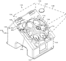
まず、コインホッパ100の概要が図1を参照して説明される。
本実施例において単にコイン102というときは大径コイン102L及び小径コイン102Sの両方を含んでいる。
コインホッパ100は、バラ積み状態で保留された円板形のコイン102を一つずつ払い出す機能を有する。
コインホッパ100は、少なくともフレーム104、ホッパベース106、保留ボウル108、回転ディスク110、コイン102の周方向案内装置112、弾出装置114(図4参照)、出口通路116、コイン検知装置118(図6参照)、出口通路画定装置122を含んでいる。
First, an outline of the
In the present embodiment, the
The
The
まずフレーム104が図1を参照して説明される。
フレーム104はホッパベース106及び保留ボウル108を支持する機能を有し、樹脂にて射出成型された矩形の筒状をしている。
フレーム104は、下端のベース124、及び、ベース124に一体化され上向きに延びる矩形筒形のサポート部126を含んでいる。
サポート部126の中空部には、制御基板や回転ディスク110の駆動のための電気モータ等が配置され、頭部は斜めに形成されている。
First, the
The
The
In the hollow portion of the
次にホッパベース106が図2〜図4を参照して説明される。
ホッパベース106は、保留ボウル108、回転ディスク110、周方向案内装置112、弾出装置114、及びコイン検知装置118を所定の位置に保持する機能、及び、回転ディスク110によって移動されるコイン102を案内する機能を有する。
ホッパベース106は、矩形の厚板状を呈し、サポート部126の頂部に固定されている。
換言すれば、ホッパベース106は、所定の角度で傾斜している。
Next, the
The
The
In other words, the
ホッパベース106は上面128の中央に位置する有底かつ円形鍋形のガイド穴132、上下端部に形成した保留ボウル108の第1取付部134A、134B及び第2取付部136A、136B、ガイド穴132の周面の一部を開口した出口開口138、裏面側にコイン検知装置118の第1取付部140及び周方向案内装置112の第2取付部142(図6参照)を含んでいる。
ガイド穴132の底面144は、大凡平面であり、中央に、回転ディスク110を取り付ける回転軸146が貫通する軸孔147が形成されている。
ガイド穴132の周壁150は、C形の金属製ガイドリング148の内周面及び後述のガイド体196の第1側面208又は第2側面212によって構成される。
底面144は後述のように本実施例では金属板258の上面によって構成されるが、ホッパベース106と一体に樹脂成形することができる。
回転ディスク110によって押動されるコイン102は、その下面がガイド穴132の底面144上を滑りつつ、かつ、その周面がガイド穴132の内周面である周壁150に案内されつつ移動する。
出口開口138に臨んで後述の弾出装置114が配置されている。
厳密に言えば、後述の第1ガイド188及び第2ガイド192によって出口開口138が構成される。
The
A
The
As will be described later, the
The
A later-described
Strictly speaking, an
次に、保留ボウル108が図1を参照して説明される。
保留ボウル108は、コイン102をバラ積み状態に貯留する機能を有する。
保留ボウル108の下端部152は、ガイド穴132とほぼ同一径の円筒状であって、ホッパベース106に対し直交方向に延びている。
換言すれば、下端部152は斜め上方に向かって伸びており、その上端部154は四角形状に拡大形成され、上端はコイン102を投入するための上部開口156になっている。
下端部152の円筒内の底孔158に回転ディスク110の上部が配置されている。
保留ボウル108の上端部154と下端部152は傾斜壁によって接続され、その上に乗ったコイン102は、重力によって自然滑落し、下方の回転ディスク110上に落下する。
第1取付部134A、134B及び第2取付部136A、136Bに保留ボウル108の下部に形成した係止部(図示せず)を係止することにより、保留ボウル108を簡単操作でホッパベース106に取付け、取外しできるようにしてある。
Next, the
The holding
The
In other words, the
An upper portion of the
The
The retaining
次に回転ディスク110が図2及び図5を参照して説明される。
回転ディスク110は、保留ボウル108にバラ積み状態に保留されるコイン102を一つずつ区分けし、弾出装置114に搬送する機能を有する。
回転ディスク110は、電気モータ162(図6参照)によって減速機164を介して回転駆動される。
回転ディスク110には、回転軸線Cを中心とする所定半径の円上であって等間隔に円形の通孔166が形成され、通孔166の上面側は、下向き錐形の導入部168が形成されている。
通孔166は、大径コイン102L又は小径コイン102Sが使用された場合であっても、回転ディスク110を交換せずとも良いよう、大径コイン102Lよりも僅かに大きく形成されている。
また、中央部には円錐形であって、かつ、回転軸146を取付けると共にコイン102の攪拌のための中央凸部172(図3参照)が形成されている。
回転ディスク110は、その下部がガイド穴132内にその周面が周壁150に対しコイン102の厚みよりも狭い間隔で、また、その上部は保留ボウル108の下端部152の底孔158内に僅かな隙間を空けて配置されている。
Next, the
The
The
On the
The through-
Further, a conical shape is formed at the central portion, and a central convex portion 172 (see FIG. 3) for attaching the
The
回転ディスク110の裏面160である通孔166を区画するリブ170の下面には、コイン102を押し出すための第1押動部174及び第2押動部176が通孔166のそれぞれに相対して下向きに突出形成されている。
第1押動部174及び第2押動部176の第1押動面174A、及び第2押動面176A(図5参照)は、回転ディスク110の中心部から伸びるインボリュート曲線上に位置している。
第1押動部174と第2押動部176との間には、後述の周方向案内装置112を構成する第1規制体112A通過のための第1溝178A及び、第2規制体112B通過のための第2溝178Bが形成されている。
A first pushing
The first pushing
Between the first pushing
回転ディスク110が回転した場合、その上に載っているコイン102は通孔166、中央凸部172等によって攪拌され、姿勢が変化させられて通孔166に落下する。
落下したコイン102の下面はガイド穴132の底面144(金属板258の上面)に、外周は周壁150によって案内される。
そして、回転ディスク110の回転によって第1押動面174A及び第2押動面176Aによって押動されて回転ディスク110と共に連れ回りされる。
このとき、コイン102の周面は周壁150に案内されるが、周壁150に対する接触圧は殆どが遠心力に基づくものであるので大きな接触圧ではない。
連れ回り過程において、周方向案内装置112の第1規制体112A、及び第2規制体112Bによって連れ回りを阻止されたコイン102は、回転ディスク110の周方向へ案内され、最終的に第2押動面176Aによって、出口開口138へ押し込まれる。
When the
The lower surface of the dropped
Then, the
At this time, the peripheral surface of the
In the follow-up process, the
次に周方向案内装置112が図4を参照して説明される。
周方向案内装置112は、第1押動部174、第2押動部176によって押動されるコイン102を、回転ディスク110の周方向に案内し、出口開口138に誘導する機能を有する。
具体的には、ホッパベース106を下側から上側に貫通し、回転ディスク110の裏面160に向かって伸びる円柱ピン状の第1規制体112A及び第2規制体112Bが配置されている。
換言すれば、第1規制体112A及び第2規制体112Bはコイン102の移動経路182に突出している。
Next, the circumferential guide device 112 will be described with reference to FIG.
The circumferential direction guiding device 112 has a function of guiding the
Specifically, cylindrical pin-shaped first restricting
In other words, the first restricting
第1規制体112A及び第2規制体112Bは、ホッパベース106の裏面の第2取付部142に一端を固定された板バネ184A、184B(図6参照)にそれぞれ固定されている。
これにより、第1押動部174、第2押動部176によって押動されるコイン102は第1規制体112A及び第2規制体112Bによって回転ディスク110による連れ回りを阻止され、出口開口138側へ案内される。
なお、第1規制体112A又は第2規制体112Bの一方のみ、若しくは第1規制体112A及び第2規制体112Bを用いずともコイン102が出口開口138に自ずと移動する場合、それらを配置する必要はない。
The first restricting
As a result, the
In addition, when the
換言すれば、回転ディスク110の直径が大きく、第1押動部174及び第2押動部176によってコイン102を回転ディスク110の周方向へ誘導できる場合、第1規制体112A及び第2規制体112Bを配置する必要は無い。
第1規制体112A及び第2規制体112Bがコイン102から所定の横方向の力を受けた場合、板バネ184A、184Bが弾性変形して第1規制体112A及び第2規制体112Bは底面144の下方に向かって移動可能であり、コイン102がそれを乗り越えて移動可能になり、回転ディスク110と共に移動できる。
In other words, when the diameter of the
When the first restricting
次に出口開口138が図4を参照して説明される。
出口開口138は、周方向案内装置112の側方のガイド穴132の周壁150が所定長にわたって切除された矩形の開口である。
実施例においては、第1ガイド188及び第2ガイド192によってコイン102の出口が画定されるので、これらの間が出口開口138である。
出口開口138の長さ(ガイド穴132の周方向の長さ)は、コイン102が通過するに十分な長さである。
換言すれば、周壁150はコイン102の直径よりも横方向の長さが僅かに大きく形成され、その開口に実質的に出口開口138を構成する第1ガイド188及び第2ガイド192が配置される。
Next, the
The
In the embodiment, since the exit of the
The length of the outlet opening 138 (the circumferential length of the guide hole 132) is sufficient for the
In other words, the
次に弾出装置114を図4及び図6を参照して説明する。
弾出装置114は、回転ディスク110によって一枚ずつ区分けされて送り出されるコイン102をひとつずつ弾き出す機能を有する。
弾出装置114は、第1ガイド188、第2ガイド192及び付勢手段194を含んでいる。
Next, the ejecting
The ejecting
The ejecting
まず第1ガイド188が図4を参照して説明される。
第1ガイド188は、コイン102が弾き出される際、出口開口138の一側を固定的に画定する機能を有する。
さらに、本実施例においては、コイン102として小径コイン102S又は大径コイン102Lの何れが使用される場合であっても、第2ガイド192の移動量が同一になるようにする機能を有する。
本実施例における第1ガイド188は、へら状の板金製ガイド体196の弧状端部198によって構成されている。
詳述すれば、ガイド体196の一端の角部の1つが第1ガイド188を構成し、当該ガイド体196の表裏を反転させた際の前記角部に相対する他の角部が第1ガイド188を構成する。
First, the
The
Further, in the present embodiment, the
The
More specifically, one corner of one end of the
ガイド体196は他端部202及び側部凸部204が形成され、ホッパベース106に形成された凹部207に側部凸部204が位置し、かつ、他端部202がガイドリング148の一端の弧状凹部206に接した状態において、小径コイン102Sに適した第1位置P1に位置するよう設定されている。
この状態において、ガイド体196の直線状の第1側面208はガイド穴132の一部を構成する。
図4において鎖線で示すように、ガイド体196を表裏反転した場合、第1側面208の反対側の第2側面212がガイド穴132の一部を構成する。
このとき、第1側面208はホッパベース106の端部に立設する垂立壁210に、及び他端部202がガイドリング148の凹部214に係合することにより位置決めされる。
第2側面212は、第1側面208よりも湾曲しており、ガイド穴132の実質的半径を大きくしている。
換言すれば、大径コイン102Lが第1規制体112A、第2規制体112Bによって出口開口138へ案内され、かつ、第2ガイド192が小径コイン102Sが弾き出される場合と同一の移動量になるよう設定されている。
The
In this state, the linear
As indicated by a chain line in FIG. 4, when the
At this time, the
The
In other words, the large coin 102L is guided to the
次に第2ガイド192が図4を参照して説明される。
第2ガイド192は移動可能に設けられ、第1ガイド188との間でコイン102を挟んで弾き出す機能を有する。
第2ガイド192は、本実施例では支軸216に回転自在に支持されたローラ218である。
第2ガイド192は、回転ディスク110及び第1ガイド188の側方に配置され、出口開口138の一側壁を構成している。
Next, the
The
The
The
支軸216は、ホッパベース106の裏面に下向きに固定された固定軸222にピボット運動可能に取り付けられた揺動レバー224の一端部に固定され、ホッパベース106の弧状長孔226を通って、第1ガイド188に対し所定距離離れ、かつ出口通路116に隣接して位置している。
図6に示すように、ホッパベース106の下面に突出するピン228と揺動レバー224から下方に突出する支軸216との間に掛止めした付勢手段194、具体的にはスプリング232が掛止され、ローラ218が第1ガイド188に近づくよう図4において反時計方向(図6において時計方向)に付勢されている。
The
As shown in FIG. 6, a biasing means 194, specifically a
付勢手段194は、第2ガイド192を第1ガイド188に弾性的に近づける機能を有している。
通常、揺動レバー224は一体に形成された被係止部234が、ホッパベース106の裏面に形成された表面が弾性的に形成された係止部236によって係止されることにより、第1ガイド188に対しコイン102の直径よりも小さい間隔で停止された待機位置SPにおいて静止している。
係止部236は、例えばホッパベース106の裏面に突出するピンに外装したゴムリング238である。
係止部236を弾性体により構成することにより、揺動レバー224のバウンドを抑制し、コイン検知装置118が誤検知することを防止できる。
The urging means 194 has a function of elastically bringing the
Usually, the rocking
The locking
By configuring the locking
コイン102の中心を通る直線が第1ガイド188と第2ガイド192との間に進行した場合、図4に鎖線示するように第2ガイド192は弾き出し位置DPに移動された後、スプリング232の弾発力でコイン102を出口通路116へ弾き出す。
なお、第2ガイド192は揺動レバー224によってピボット運動を行うが、直線運動により第1ガイド188に対し接近、離隔するよう変更することができる。
また、付勢手段194は、スプリングの他、電磁アクチュエータ、空気アクチュエータ等同様の機能を有する装置に変更することができる。
When a straight line passing through the center of the
The
Further, the urging means 194 can be changed to a device having a similar function such as an electromagnetic actuator and an air actuator in addition to the spring.
次にコイン検知装置118が図4及び図6を参照して説明される。
コイン検知装置118は、コイン102による第2ガイド192の移動を直接的又は間接的に検知して検知信号DSを出力する機能を有する。
実施例のコイン検知装置118は、第2ガイド192、第2ガイド192を支持する揺動レバー224、揺動レバー224と一体的に移動する作用片242及び作用片242の検知装置244を含んでいる。
Next, the
The
The
作用片242は、揺動レバー224と一体に、第2ガイド192よりも支軸216から遠い位置に形成され、固定軸222を中心とする円弧状に所定の長さで延在する被検知部246である。
検知装置244は、被検知部246を検知した場合、「H」又は「L」の電気的な検知信号DSを出力する機能を有する。
実施例の検知装置244は、透過形の光電センサ248であり、透孔248H(図4参照)から投光される投射光が遮断された場合、検知信号DSを出力する。
光電センサ248は、ホッパベース106の裏面の第1取付部140に取付ブラケット250を介して固定されている。
The
The
The
The
実施例において光電センサ248はサポート部126で囲われたホッパベース106の下方に位置するので、外部から不正にアクセスすることが極めて困難である。
コイン102によって第2ガイド192が弾き出し位置DPへ移動された場合、図4において鎖線で示すように被検知部246が透孔248Hに相対する場合、透孔248Hから受光部への投射光を遮断する。
この遮断によって、光電センサ248の出力は「H」から「L」になる。
第2ガイド192が弾き出し位置DPから待機位置SPへ移動する場合、移動途上において被検知部246が透孔248Hから外れるので、光電センサ248の出力は「L」から「H」になる。
光電センサ248の出力が「L」から「H」に変化したときに検知信号DSを出力する。
この検知信号DSをカウントすることにより、払い出したコイン102の数を知ることができる。
したがって、検知装置244は、同様の機能を有する他の方式、例えば反射式光電センサ、金属センサ等他のセンサに変更することができる。
さらに、揺動レバー224または第2ガイド192の移動を直接検知することによりコイン検知装置118を構成することができる。
In the embodiment, since the
When the
By this interruption, the output of the
When the
When the output of the
By counting this detection signal DS, the number of
Therefore, the
Furthermore, the
次に出口通路116が図4を参照して説明される。
出口通路116は、弾出装置114によって弾き出されたコイン102を案内する機能を有する。
出口通路116は、出口開口138に連続して回転ディスク110の周方向に伸びる薄板状の通路である。
出口通路116は、ホッパベース106に形成された凹溝252、第1ガイド188、第2ガイド192及び凹溝252の上側解放面を覆う出口通路画定ガイド254によって画定され、回転ディスク110の周方向に伸びている。
凹溝252の底面256は、底面144と同一平面内に配置され、弾出装置114によって弾き出されたコイン102の下面が案内される。
底面144は、ガイド穴132の形状に形成した金属(ステンレス)板258の上面である。
底面144を導電性の金属板にすることにより」、樹脂製の回転ディスク110とコイン102との摩擦によって発生した静電気を、この底面144を介してアースすることができるので、静電気による電子部品等の破損等の問題を解消できる利点がある。
出口通路画定装置122は、本実施例においてはホッパベース106及び出口通路画定ガイド254により構成される。
Next, the
The
The
The
The
The
By making the bottom surface 144 a conductive metal plate ", static electricity generated by friction between the resin
The outlet
次に第1ガイド188の仮位置決め装置259が図4を参照して説明される。
仮位置決め装置259はガイド体196を第1位置P1又は第2位置P2に仮決めする機能を有し、第1ダボ孔260、第2ダボ孔262及びベースダボ264を含んでいる。
第1ガイド188には、第1位置P1への位置決め用の第1ダボ孔260及び第2位置P2への位置決め用の第2ダボ孔262が形成されている。第1ダボ孔260及び第2ダボ孔262は所定直径の円形をしている。
第1ダボ孔260、第2ダボ孔262に嵌合可能に金属板258の表面に円柱状のベースダボ264が突出形成されている。
ベースダボ264に第1ダボ孔260が嵌合し、他端部202が弧状凹部206に係合し、かつ側部凸部204が凹部207に係合した場合、ガイド体196の1つの角部である弧状端部198は第1位置P1に配置される。
また、ガイド体196の表裏をひっくり返し、第2ダボ孔262をベースダボ264に嵌合し、他端部202を凹部214に係合させた場合、他方の角部である弧状端部198は第2位置P2になるよう設定されている。
Next, the
The
The
A cylindrical base dowel 264 is formed on the surface of the
When the
When the
次に出口通路画定装置122が図1〜4及び図7〜11を参照して説明される。
出口通路画定装置122は、出口通路116を画定する機能を有する。
出口通路116は、ホッパベース106の凹溝252に出口通路画定ガイド254を嵌め込んだ後、スクリュウ等の固定手段280によってホッパベース106、換言すればフレーム104に固定することにより画定形成される。
凹溝252は、図4において、ガイド穴132の上端部から横方向に延びる通路であり、その底面256はガイド穴132の底面144と同一の仮想平面内に配置されている。
具体的には、金属板258がホッパベース106の左端部まで延長されている。
そして、当該金属板258の上に第1ガイド188を構成するガイド体196が固定され、第2ガイド192と共に出口開口138を構成する。
図10に示すように凹溝252の上側の側壁268は、垂立面270と下向き斜面272とが交互に形成されている。
凹溝252の下側の側壁274は、図2に示すようにガイド穴132側へ向かって傾斜する斜面であって、底面256に対し直角上方へ延びて形成されている。
The outlet
The outlet
The
In FIG. 4, the
Specifically, the
Then, a
As shown in FIG. 10, on the
The
次に出口通路画定ガイド254が主に図8を参照して説明される。
出口通路画定ガイド254は、平板状であって、平面視倒立L形に透明樹脂で成形される。
ガイド体196が小径コイン102Sに対応する第1位置P1に設定されているか、大径コイン102Lに対応する第2位置P2に設定されているかの確認及び出口通路116におけるコイン102の移動状況を目視可能にするためである。
しかし、出口通路画定ガイド254は不透明であっても良い。
出口通路画定ガイド254のガイド穴側側面276は、回転ディスク110の周縁にコイン102の厚み未満の距離で隣接するよう回転軸146の軸心を中心とする円弧に形成され、対面する直状側面278がホッパベース106に固定された場合、ホッパベース106の左側面282と面一に配置される。
直状側面278にはホッパベース106と共にコインの出口284を構成する下向き凹部286が形成されている。
Next, the outlet
The outlet
Check whether the
However, the outlet
The guide hole
The
出口通路画定ガイド254の下面288は、平面であって、上端部(図8において左側部)下面に棒状であって、断面矩形の上側側面ガイド290が突出形成されている。
上側側面ガイド290からコイン102の直径よりも僅かに離れた位置の左端部に出口画定突起292が下向きに形成されている。
上側側面ガイド290と出口画定突起292との突出量は同一であって、コイン102の厚みよりも僅かに大きい高さh(厚く)において形成されている。
換言すれば、直状側面278には上側側面ガイド290と出口画定突起292とによって下向き凹部286が形成されている。
下向き凹部286の中間には、直状側面278からガイド穴側側面276に向かって球状であって、大人の人指し指の先端が挿入できる程度の取り出し凹部296が形成されている。出口通路116に残留するコイン102を指先で取り出し易くするためである。
下向き凹部286は、下面288の一部である上縁286A、上側側面ガイド290の側面である左側縁286L、及び出口画定突起292の側面である右側縁286Rによって構成され、取り出し凹部296は上縁286Aの中間に形成されている。
したがって、下向き凹部286に対応する下面288は直状側面278から出口開口138、換言すればガイド穴132に向かって所定長さで球面状に窪み、また、取り出し凹部296の上側側面ガイド290側の左上縁286AL(図9参照)は左側縁286L側までの間の所定の長さW1において直線状に形成され、出口画定突起292側の右側縁286Rまでの間の右上縁286ARは所定長さW2において直線状に形成されている。
取り出し凹部296の窪み形状は球面状でなくとも、ピンセット状器具又は指先によってコイン102を取り出すことができるよう窪んでいればよい。
The
An
The amount of protrusion of the
In other words, a downward
In the middle of the
Accordingly, the
The recess shape of the take-out
出口通路画定ガイド254の上側側面(上端部)から所定の幅で係止突起294が、突出している。
係止突起294には前記垂立面270及び斜面272に相対して垂立面298及び斜面300が階段状に形成されている。
係止突起294の上端部の上面302は下面288と平行に形成され、ホッパベース106に形成された係止突起294の幅よりも僅かに大きい幅を有する係止凹部308(図4、10参照)に係合可能である。
上面302と上側側面ガイド290の下端との距離H1(図8(B)参照)は、上側側面ガイド290の下端304が当接する底面256と係止凹部308の下面との間の距離H2(図10参照)よりも僅かに大きく形成されている。
これにより、係止突起294がホッパベース106に密に保持されるので出口通路画定ガイド254が振動することがなく、コイン102の払い出しに悪影響を及ぼさないからである。
出口通路画定ガイド254には上下方向に貫通する第1貫通孔314A、第2貫通孔314B並びに第3貫通孔314C及び第2貫通孔314B近傍の下面288から下向きに円柱ピン状の出口通路画定ガイドダボ326が突出形成されている。
出口通路画定ガイド254の中間の中央には第1貫通孔314Aが形成され、第1貫通孔314Aに近接して第3貫通孔314Cが形成されている。
第1貫通孔314Aは、ガイド体196が第1位置P1に配置され、かつ第1ダボ孔260がベースダボ264に嵌合した場合、貫通孔214A及び底面256に形成されたネジ孔316Aと同一軸線上に位置し、上下方向に重なり合う。
また、第2貫通孔314Bはガイド体196が第1位置P1に配置され、かつ第1ダボ孔260がベースダボ264に嵌合した場合、貫通孔214B及び底面256に形成されたネジ孔316Bと同一軸線上に位置し、上下方向に重なり合う。
換言すれば、固定手段280としてのスクリュウ312Aを第1貫通孔314A、貫通孔212Aを貫通して底面144のネジ孔316Aに、スクリュウ312Bを第2貫通孔314B、貫通孔212Bを貫通して底面144のネジ孔316Bにねじ込んでガイド体196及び出口通路画定ガイド254をホッパベース106に、換言すればフレーム104に一体に固定でき、それらが重なり合わなければ固定することができない。
ガイド体196が第2位置にある場合、換言すれば第2ダボ孔262がベースダボ264に嵌合した場合、貫通孔212Aが底面144のネジ孔316Cに重なり、かつ出口通路画定ガイド254の第3貫通孔314Cが貫通孔214C及びネジ孔316Bに重なり合い、それぞれスクリュウ312A、312Bをネジ孔316C及び316Bにねじ込んでホッパベース106に固定することができる。
出口通路画定ガイドダボ326は第2貫通孔314Bの近傍の下面288から下向きに突出する円筒形のピンである。
ガイド体196の第1位置P1において第1ダボ孔260に、第2位置P2において第2ダボ孔262に嵌合して出口通路画定ガイド254を位置決めする。
A locking projection 294 protrudes from the upper side surface (upper end portion) of the outlet
A vertical surface 298 and an inclined surface 300 are formed in a stepped manner on the locking projection 294 so as to be opposed to the
The upper surface 302 of the upper end portion of the locking projection 294 is formed in parallel with the
A distance H1 between the upper surface 302 and the lower end of the upper side guide 290 (see FIG. 8B) is a distance H2 between the
This is because the locking projection 294 is tightly held on the
The outlet
A first through hole 314A is formed at the middle center of the outlet
When the
The second through hole 314B is the same as the
In other words, the
When the
The outlet passage defining guide dowel 326 is a cylindrical pin that protrudes downward from the
The outlet
次に出口通路画定ガイド254をホッパベース106に固定する作業を説明する。
係止突起294を係止凹部308に挿入し、上側側面ガイド290の下端304を底面256に押し付けた状態で出口通路画定ガイド254の下端部(図8において右端部)を下方へ押し下げる。
この後、下面288をガイド体196の上面に押し付けた状態で固定手段280としての固定用スクリュウ312A、312Bを第1貫通孔314A又は第3貫通孔314C、及び第2貫通孔314Bを貫通させて底面256を構成する金属板258に形成したネジ孔316A又は316C、及びネジ孔316Bにねじ込んで固定する。
ガイド体196はコイン102の厚みよりも僅かに厚い所定の厚さに形成されているので、下面288は底面256と大凡平行になる。
また、上側側面ガイド290の下端304と出口画定突起292の下端が底面256の表面に密接し、厚みがコイン102の厚みよりも僅かに大きく、かつ横幅がコイン102の直径よりも僅かに大きい細長矩形の出口284がホッパベース106の左側面282に形成される。
これにより、底面256、出口通路画定ガイド254の下面288、上側側面ガイド290及び出口画定突起292によって扁平な平板状に画定され、かつ出口開口138から出口284に向かって直線的に延びる出口通路116が画定形成される。
Next, an operation for fixing the outlet
The locking projection 294 is inserted into the
Thereafter, with the
Since the
In addition, the lower end 304 of the
Accordingly, the
図9に示すように、出口284において取り出し凹部296の左側には幅W1において底面256と平行な左上縁286AL、右側には幅W2において底面256と平行な右上縁286ARが位置する。
また取り出し凹部296よりも出口開口138側は左上縁286AL及び右上縁286ARが連続した上縁286Aによって構成される。
出口通路116の下縁286Uは底面256によって構成される。
換言すれば、出口通路116の左右(図4においては上下)にはその全長にわたってコイン102の厚みよりも僅かに厚い通路が連続的に構成されている。
したがって、出口通路116を出口開口138から出口284に向かって移動するコイン102はその両端部を底面256及び少なくとも左上縁286AL又は右上縁286ARによって案内され続けるので、コイン102の移動姿勢は安定する。
結果として、コイン102の出口284からの払い出し方向が安定するという利点がある。
また、出口284の上側中間には取り出し凹部296によって出口284から出口開口138側へ所定の長さで出口通路116の上側に位置する窪みが形成される。
As shown in FIG. 9, an upper left edge 286AL parallel to the
Further, the
The
In other words, a passage that is slightly thicker than the thickness of the
Therefore, since the
As a result, there is an advantage that the payout direction of the
In addition, a recess located on the upper side of the
図8(C)において、下面288の取り出し凹部296に相対するガイド穴側側面276から内方へ延びる長溝318は第2ガイド192の頭部が移動するための溝である。
出口通路画定ガイド254が正常にホッパベース106に固定され、かつコイン102が出口通路116に滞留した場合、コイン102の先端が出口284と大凡面一に位置する(図4鎖線示)。
コイン102が出口通路116に滞留している場合、指先を凹部196に挿入すると、先端がコイン102の上面に接触するのでコイン102を指先で押し下げて適度の摩擦力をもって引き出すように移動させることにより、コイン102を出口通路116から引き出すことができる。
In FIG. 8C, a long groove 318 extending inward from the guide
When the outlet
When the
次に、ガイド体196の位置決め装置322を主に図4及び図8を参照して説明する。
位置決め装置322は、第1位置P1若しくは第2位置P2に仮位置決めされたガイド体196を本位置決めする機能を有し、出口通路画定ガイドダボ326及びガイド体196に穿孔された第1ダボ孔260及び第2ダボ孔262を含んでいる。
換言すれば、ガイド体196の他端部202が弧状凹部206に、側部凸部204が凹部207に係合し、かつベースダボ264が第1ダボ孔260に嵌合した状態において、ガイド体196は第1ガイド188の第1位置P1に仮位置決めされる。
他方、ガイド体196の他端部202が凹部214に、かつベースダボ264が円形の第2ダボ孔262に嵌合した状態において、ガイド体196は第1ガイド188の第2位置P2に位置決めされる。
Next, the positioning device 322 for the
The positioning device 322 has a function of fully positioning the
In other words, in the state where the
On the other hand, the
出口通路画定ガイドダボ326は下面288に突出形成された円柱状の突起であって、ベースダボ264が第1ダボ孔260に嵌合した場合、第1ダボ孔260に嵌合し、ベースダボ264が第2ダボ孔262に嵌合した場合、第2ダボ孔262に嵌合するように位置が設定されている。
この構成により、前記ベースダボ264がガイド体196の第1ダボ孔260又は第2ダボ孔262に僅かに嵌合して仮位置決めされた状態において、円柱状の出口通路画定ガイドダボ326が第1ダボ孔260又は第2ダボ孔262に嵌合することにより、自動的にその位置だしが行われ本位置決めがなされる。
これにより、出口通路画定ガイド254の第1貫通孔314A又は第3貫通孔314C、及び第2貫通孔314Bがガイド体196の貫通孔212A又は214Bに相対するので、これらに固定用スクリュウ312A、312Bを貫通させて金属板258のネジ孔316A及び316Bにねじ込むことにより固定される。
ガイド体196が第2位置P2にある場合、貫通孔314Cがガイド体196の貫通孔212Aに相対するのでスクリュウ312Aはこれを貫通してネジ孔316Cにねじ込まれることができる。
The exit passage defining guide dowel 326 is a cylindrical protrusion protruding on the
With this configuration, in the state where the base dowel 264 is slightly fitted and temporarily positioned in the
Accordingly, the first through-hole 314A or the third through-hole 314C and the second through-hole 314B of the outlet
When the
出口通路画定ガイド254が正規の位置に固定された場合、出口通路116はその高さがコイン102の厚みよりも僅かに大きい厚みhを有し、かつ幅Wがコイン102の直径よりも僅かに大きい断面が扁平横長矩形の通路に形成され、出口284も同じ大きさに形成される。
出口284の中間には前述のように、出口284からガイド穴132側に向かって所定長さで取り出し凹部296が形成されるので、取り出し凹部296が形成された部分は出口通路画定ガイド254の下面288が存在しない。
換言すれば、上側側面ガイド290の左側縁286Lから取り出し凹部296の端部までの距離W1は、厚みhの距離離れて上縁と下縁が位置する。
相対する他端部の出口画定突起292の右側縁286Rから距離W2の間は右上縁286AR及び下縁286Uが距離h離れて平行に配置される。
さらに換言すれば、出口通路116の出口284近傍において、その左右端は高さhを有するスリットであり、コイン102はその両端部を底面256並びに左上縁286AL及び右上縁286ARによって案内される。
When the exit
As described above, the
In other words, the upper edge and the lower edge of the distance W1 from the
An upper right edge 286AR and a
In other words, in the vicinity of the
次に本発明に係るコインサイズ表示装置332が主に図9及び図12を参照して説明される。
コインサイズ表示装置332は、ガイド体196の第1ガイド188が第1位置P1に位置しているのか、第2位置P2に位置しているのかを直接的又は間接的に表示する機能を有する。
具体的には、ガイド体196の固定手段280による固定位置によって、出口284の近傍に配置した表示部335に設定コインを表示する機能を有する。
表示部335の表示内容としては、設定されたコインサイズ、換言すればコインの直径を表示することが好ましい。
これらの表示により、作業者は直感的に使用可能なコインサイズを理解できる。
しかし、第1位置P1又は第2位置P2のように間接的に表示することもできる。さらに、コインの直径に対応して色分けすること、特定の文字又は記号を付すこと、特定の形状とすること等間接的な表示法を採用することができる。
また、表示位置が出口284の近傍であればよいので、本実施例のように出口284と同じ仮想面内に表示部335を並列配置する他、出口284に対し直角位置である出口通路画定ガイド254の上面に配置することもできる。
Next, a coin
The coin
Specifically, it has a function of displaying the set coin on the
As the display contents of the
With these displays, the operator can intuitively understand the usable coin size.
However, it can also be indirectly displayed like the first position P1 or the second position P2. Furthermore, an indirect display method such as color-coding according to the diameter of the coin, attaching a specific character or symbol, or a specific shape can be employed.
Further, since the display position only needs to be in the vicinity of the
実施例のコインサイズ表示装置332は、表示体336及び表示窓364を含んでいる。
表示体336は、横向き部338、縦向き部358によって大凡T形に形成される。
横向き部338は、断面矩形の棒状であるが、正確には中間に段差342が形成されている。
横向き部338の一端面である第1端面344にはガイド体196が第1位置P1に位置した場合、最適のコインサイズ(直径)の第1表示部346を設ける。例えば、直径25ミリに相当する「25」を浮き文字又は窪み文字に成形し、第1表示部346を構成する。浮き文字等に代えて数字を印刷したシールを貼付することができる。
また、第1端面344が後述の表示窓364に位置する場合、表示体336の上面にも第1端面344と同一のコインサイズを表示する上面第1表示部348を設けることが好ましい。
コインホッパ100を上方から見下ろした場合、コインサイズを容易に確認できるからである。
The coin
The
The laterally facing
When the
In addition, when the
This is because the coin size can be easily confirmed when the
横向き部338の他端面である第2端面352にはガイド体196が第2位置P2に位置した場合、最適のコインサイズ、例えば直径30ミリに相当する「30」を浮き文字等に成形し、第2表示部354を構成する。
第2表示部354が表示窓364に位置する場合、表示体336の上面にも第2端面352と同一のコインサイズを表示する上面第2表示部356を設けることが好ましい。
表示体336の断面矩形の縦向き部358の端部に円形の貫通孔362が形成されている。
第1端面344が表示窓364に位置する場合、貫通孔362は第1貫通孔314Aに相対可能に形成され、第2端面352が表示窓364に位置する場合、貫通孔362は第3貫通孔314Cに相対可能に形成されている。
換言すれば、第1表示部346が表示窓364に位置する場合、貫通孔362は第1貫通孔314Aの軸線と同軸に配置されることができ、第2表示部354が表示窓364に配置された場合、貫通孔362は第1貫通孔314A又は第3貫通孔314Cの軸線と同軸に配置されることができない。
また、第2表示部354が表示窓364に位置する場合、貫通孔362は第3貫通孔314Cの軸線と同軸に配置されることができ、第1表示部346が表示窓364に配置された場合、貫通孔362は第1貫通孔314A又は第3貫通孔314Cの軸線と同軸に配置されることができない。
When the
When the
A circular through
When the
In other words, when the
Further, when the
第1表示部346及び第2表示部354は、出口通路画定ガイド254の側面278に形成した矩形の表示窓364に嵌合された場合、前記固定位置に位置決めされるように設定されている。
出口284を正面から見た場合、設定されているコインサイズが容易に確認できるからである。
実施例において、表示体336は出口通路画定ガイド254の上側にあてがわれ、スクリュウ312Aによって出口通路画定ガイド254及びガイド体196と共締めされることにより固定される。
詳述すれば、ガイド体196が第1位置P1に位置する場合、第1位置P1に対応する直径25ミリのコインサイズを表示する第1表示部346が形成された第1端面344を有する横向き部338の端部(図12において左端部)が表示窓364に相対した位置、正確には嵌り合った位置において、貫通孔362が第1貫通孔314A及び貫通孔212Aに重なり、スクリュウ312Aがこれら貫通孔212A、314A及び362を貫通してネジ孔316Aにねじ込み可能になる。
誤って第2端面352を表示窓364に相対させた場合、正確には第2端面352を有する横向き部338の端部が表示窓364に嵌め込んだ場合、貫通孔362は第1貫通孔314Aに重ね合わせることができない。
一方、貫通孔362を第1貫通孔314Aに重ね合わせた場合、第2端面352側の横向き部338の端部は表示窓364に嵌め合わされることができず、表示窓364に相対できない。
The
This is because when the
In the embodiment, the
More specifically, when the
If the
On the other hand, when the through
横向き部338は段差342によって僅かにクランク形に折り曲げられ、第2端面352は第1端面344よりも貫通孔362に対し遠い位置に形成されているからである。
さらに、貫通孔362の中心を通り、かつ縦向き部358の中心を通る直線Lに対し、第2端面352は第1端面344よりも距離が短いためである。
換言すれば、第2端面352側の横向き部338の端部が表示窓364に嵌め合わされた場合、貫通孔362は第1貫通孔314Aに重なり合わないのでスクリュウ312Aをねじ込むことができない。
以上の説明より明らかなとおり、ガイド体196が第1位置P1に位置している場合、第2端面352側の端部を表示窓364に位置させようとした作業者は、表示が間違いであることに容易に気づき、第1端面352側を表示窓364に嵌め合わせた正しい位置においてスクリュウ312Aをネジ孔316Aにねじ込んで表示体336、出口通路画定ガイド254及びガイド体196を共締めして固定することができる。
一方、ガイド体196が第2位置P2に位置する場合、第2端面352側の横向き部338の端部を表示窓364に挿入した位置において貫通孔362は貫通孔212A、第3貫通孔314Cに重なり合い、スクリュウ312Aをネジ孔316Cにねじ込んで表示体336、出口通路画定ガイド254及びガイド体196を共締めして固定することができる。
この状態で第1端面344側の横向き部338を表示窓364に挿入した場合、貫通孔362は第3貫通孔314Cからずれた位置にあり、スクリュウ312Aをネジ孔316Cにねじ込むことができないので表示窓364に間違ったサイズ表示がなされることはない。
This is because the
Furthermore, this is because the
In other words, when the end portion of the
As is clear from the above description, when the
On the other hand, if the
When the
次に実施例の作用を説明する。
本実施例において、小径コイン102Sは直径25ミリ、大径コイン102Lは直径30ミリに設定されている。
まず、小径コイン102Sに適した仕様に設定する作業を説明する。
ガイド体196は、他端部202が弧状凹部206に、側部凸部204が凹部207に係合し、かつ第1ダボ孔260がベースダボ264に嵌合されて第1位置P1に仮位置決めされる。
換言すれば、第1ガイド188が直径25ミリの小径コイン102Sに適した位置に仮決めされると共に、貫通孔212Aは第1ネジ孔316Aに、貫通孔214Bはネジ孔316Bに重なり合う。
次に出口通路画定ガイド254の係止突起294をホッパベース106の係止凹部308に挿入して下面288がガイド体196の上面に密着するまで押し下げる。
この押し下げ時、出口通路画定ガイドダボ326が第1ダボ孔260に嵌合する。
これにより、出口通路画定ガイド254の本位置決めが自動的に行われ、貫通孔212Aに第1貫通孔314Aが、貫通孔214Bに第2貫通孔314Bが重なり合う。
この状態において、ガイド体196の貫通孔212Aと出口通路画定ガイド254の第1貫通孔314A、貫通孔212Bと第2貫通孔314Bとが重なりあう。
換言すれば、スクリュウ312Aを第1貫通孔314A及び貫通孔212Aを貫通させてネジ孔316Aにねじ込み、かつ貫通孔212Bと第2貫通孔314Bを貫通させてネジ孔316Bにスクリュウ312Bをねじ込むことにより出口通路画定ガイド254及びガイド体196を共締めにより固定可能である。
続いて表示体336の第1表示部346側の横向き部338の先端を表示窓364に挿入し、貫通孔362を第1貫通孔314Aに重ね合わせる。
この状態で、スクリュウ312Aを貫通孔362、第1貫通孔314A及び貫通孔212Aに貫通し、スクリュウ312Bを第2貫通孔314B及び貫通孔212Bを貫通させてネジ孔316A又は316Bにそれぞれねじ込み、ガイド体196、出口通路画定ガイド254及び表示体336を共締めによりホッパベース106に固定する。
これにより、ガイド体196は第1位置P1に固定され、第2ガイド192と共に小径コイン102Sの直径に適した出口開口138を構成すると共に、上側側面ガイド290、出口画定突起292、底面258及び下面288によって横長矩形の出口通路116が画定形成され、出口通路116のホッパベース106の側面に位置する端面が出口284として形成される。
Next, the operation of the embodiment will be described.
In this embodiment, the
First, an operation for setting a specification suitable for the small-
The
In other words, the
Next, the locking projection 294 of the outlet
At the time of this depression, the outlet passage defining guide dowel 326 is fitted into the
Accordingly, the main positioning of the outlet
In this state, the through
In other words, by screwing the
Subsequently, the tip of the
In this state, the
As a result, the
コイン102の払出指示信号を受けた場合、電気モータ162が回転し、減速機164及び回転軸146を介して回転ディスク110が図2において時計方向に回転される。
回転ディスク110の回転により、小径コイン102Sは通孔166に落下し、その下面はガイド穴132の底面144に支えられる。
さらに、小径コイン102Sは第1押動部174(第1押動面174A)及び第2押動部176(第2押動面176A)により押されてその下面は底面144上を滑り、かつ、周面は周壁150に案内されつつ回転ディスク110と共に連れ回りされる。
このとき、小径コイン102Sは第2押動部176によりその外向き円弧面を押されるので小径コイン102Sを回転中心側に押す力を受け、回転による遠心力が小径コイン102Sに作用するものの周壁150、及び第1側面208の接触圧力はほぼゼロの状態で移動する。
When the
Due to the rotation of the
Further, the small-
At this time, since the small-
小径コイン102Sは、自ら又は周方向案内装置112によって回転ディスク110の周方向に案内される。
このとき、第1規制体112A又は第2規制体112Bには横方向から力が加わるが、底面144に対しほぼ垂直状態を保つ。
小径コイン102Sの周方向への移動により、小径コイン102Sは第1ガイド188と第2ガイド192との間に達する(図4鎖線示)。
第2ガイド192は、小径コイン102Sによって移動されるまで待機位置SPに位置する。
光電センサ248は、第2ガイド192が待機位置SP近傍に位置する場合、検知信号DSを出力しない。
The small-
At this time, force is applied to the first restricting
Due to the movement of the small-
The
The
小径コイン102Sは、第1押動部174に引き続いて第2押動部176によってさらに周方向へ押され、かつ、第1ガイド188は固定であるので、第2ガイド192が小径コイン102Sによって待機位置SPから弾き出し位置DPへ移動される(図4鎖線示)。
これにより、揺動レバー224が固定軸222を中心に時計方向へ回動される。
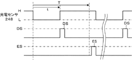
この弾き出し位置DPへ移動する途上において、作用片242は透孔248Hに相対し、投光部からの投射光を遮断するため、光電センサ248の出力は「H」から「L」に変化する。
図13に示すように、図示しない制御装置は出力が「H」から「L」に変化した時点から計時tを開始する。
The small-
As a result, the
In the middle of moving to the ejection position DP, the
As shown in FIG. 13, a control device (not shown) starts measuring time t from when the output changes from “H” to “L”.
小径コイン102Sは、その中心が当該小径コイン102Sと第1ガイド188及び第2ガイド192との接点を結ぶ直線上を通過した直後に付勢手段194の弾発力によって第2ガイド192を介してほぼ横方向に弾き出され、出口通路116を通って出口284から払い出される。
これにより、第2ガイド192は待機位置SPに戻る。
The small-
As a result, the
第2ガイド192の待機位置SPへの復帰動に連動して作用片242が光電センサ248に対する遮光を中断するので、投光部からの投射光が受光部に受光されるようになる。
これにより、光電センサ248の出力は「L」から「H」に変化する。
この「L」から「H」への出力変化に基づいて検知装置244は検知信号DSを出力する。
したがって、この検知信号DSをカウントすることにより出口284から払い出されたコイン102の数を計数することができる。
また、「H」から「L」に変化した後、「L」の継続時間tが所定時間Tよりも短い場合、異常信号は出力されない。
光電センサ248の出力「L」の継続時間tが所定時間T、例えば通常の二倍以上継続した場合、異常状態であるとして異常信号ESを出力することができる。
例えば、「L」の継続時間がコインの2枚払出に要する時間を経過した場合、異常信号ESを出力し、これに基づいて電気モータ162の回転を停止することができる。
In conjunction with the return movement of the
As a result, the output of the
Based on the output change from “L” to “H”, the
Therefore, by counting this detection signal DS, the number of
Further, after the change from “H” to “L”, if the duration “t” of “L” is shorter than the predetermined time T, no abnormal signal is output.
When the duration “t” of the output “L” of the
For example, when the time required for paying out two coins has elapsed for “L”, the abnormality signal ES is output, and based on this, the rotation of the
小径コイン102Sが出口通路116に滞留した場合、小径コイン102Sの先端が大凡出口284において停止している。
この場合、指先を取り出し凹部296に挿入し、小径コイン102Sの上面を押して摩擦力を付与した後、指先を引き出す。
これにより、小径コイン102Sは指先との摩擦力によって引き出され、出口通路116から排除できる。
指先に代えてピンセットにてつまみ出すこともできる。
この場合、底面256側にも凹部を形成することにより掴みやすくなるので残留コインの除去を容易に行うことが出来る。
When the
In this case, the fingertip is taken out and inserted into the
As a result, the small-
It can be picked up with tweezers instead of the fingertips.
In this case, since the concave portion is also formed on the
また、表示体336は第1端面344が表示窓364に嵌め合わされているので、出口284を正面から見た場合、その直近に小径コイン102Sの直径25ミリに相当する第1端面344の「25」が見えるので、適合コインの直径を一目で確認できる利点がある。
In addition, since the
次に大径コイン102Lに適した仕様に変更する作業を説明する。
スクリュウ312A、312Bを緩め、出口通路画定ガイド254を取り外す。
次いでガイド体196を裏返して他端部202を凹部214に係合した状態で第2ダボ孔262をベースダボ264に嵌合し、第2位置P2に仮位置決めする。このとき、第1側面208はホッパベース106の側壁に接する。
換言すれば、第1側面208を前記側壁に接触させて他端部202が凹部214に接触するまで底面144上をスライドさせることにより、第2ダボ孔262にベースダボ264が嵌合するので極めて位置決めが容易にできる。
Next, an operation for changing to a specification suitable for the large-diameter coin 102L will be described.
The
Next, the
In other words, very positioning since
次に係止突起294をホッパベース106の係止凹部308に係合した後、下面288をガイド体196の上面に密着させる。
このとき出口通路画定ガイドダボ326が第2ダボ孔262に嵌合し、出口通路画定ガイド254の位置決めが行われる。
この状態において、第3貫通孔314Cは貫通孔212A及び金属板258のネジ孔316Cに重なり、第2貫通孔314Bはガイド体196の貫通孔214C及びネジ孔316Bに重なる。
次に表示体336の第2表示部354側の横向き部338の先端を表示窓364に挿入し、貫通孔362を貫通孔314Cに重ね合わせる。
この状態で、スクリュウ312Aを貫通孔362、第3貫通孔314C及び貫通孔212Aに、スクリュウ312Bを第2貫通孔314B及び貫通孔214Cに貫通させてネジ孔316C、316Bにそれぞれねじ込み、ガイド体196、出口通路画定ガイド254及び表示体336を共締めして固定する。
これにより、出口384を正面から見た場合、表示窓364にガイド体196の第2位置P2に対応する大径コイン102Lの直径を示す第2端面352の「30」が見えるので、対応するコインサイズを容易に黙視確認できる。
Next, after engaging the locking projection 294 with the
At this time, the outlet passage defining guide dowel 326 is fitted into the
In this state, the third through hole 314C overlaps the through
Next, the tip of the
In this state, the
As a result, when the exit 384 is viewed from the front, the
大径コイン102Lが使用される場合も前述の小径コイン102Sの場合と同様に、払い出される。
唯一変更され点は、第2位置P2に固定された第1ガイド188と第2ガイド192とによって、弾き出される点が異なる。
しかし、第2ガイド192の弾き出し位置DPは小径コイン102Sが使用される場合と変わらない。
したがって、大径コイン102Lが使用される場合も前述の小径コイン102Sが使用される場合と同様にコイン102と検知信号DSとは一対一の関係で払い出される。
また出口通路116に滞留した大径コイン102Lを引き出す場合も小径コイン102Sと同様に引き出すことができる。
When the large-diameter coin 102L is used, it is paid out as in the case of the small-
The only change is that the
However, the ejection position DP of the
Therefore, even when the large-diameter coin 102L is used, the
Further, when the large-diameter coin 102L staying in the
108 コイン保留ボウル
110 回転ディスク
102 コイン
188 第1ガイド
192 第2ガイド
114 弾出装置
116 出口通路
156 上部開口
158 底孔
166 通孔
196 ガイド体
198 ガイド部
212A、212B ガイド貫通孔
254 出口通路画定ガイド
260、262 ダボ孔
284 出口
316A、316B、136C ネジ孔
332 表示装置
322 位置決め装置
264 ベースダボ
336 表示体
346、354 表示部
344 第1端面
346 第1表示部
354 第2表示部
338 横向き部
358 縦向き部
352 第2端面
362 表示体貫通孔
108 Coin hold bowl
110 Rotating disc
102 coin
188 First guide
192 Second guide
114 Projectile device
116 Exit passage
156 Top opening
158 Bottom hole
166 Through hole
196 Guide body
198 Guide section
212A, 212B Guide through hole
254 Exit passage definition guide
260, 262 Dowel hole
284 Exit
316A, 316B, 136C Screw hole
332 Display device
322 Positioning devices
264 base dowels
336 Indicator
346, 354 Display section
344 First end face
346 1st display
354 Second display
338 Horizontal part
358 Vertical section
352 Second end face
362 Display body through hole
Claims (1)
複数のガイド部を有するプレート状のガイド体(196)の1のガイド部を選択的に前記第1ガイド(188)として構成することにより、前記第1ガイド(188)の位置が使用対象のコイン直径に対応して設定され、
前記複数のガイド部に対応した関連表示をする複数の表示部(346、354)を有する表示手段(336)と、前記ガイド体(198)及び前記表示手段(336)を一体的に固定する固定手段(280)と、を含むコインサイズ表示装置(332)を備え、
前記固定手段(280)は、前記ガイド体(196)の選択された1のガイド部が前記第1ガイド(188)に設定された場合、前記複数の表示部(346、354)の内、当該選択されたガイド部に対応する表示部が前記出口(306)に並置された場合にのみ前記ガイド体(196)及び表示手段(336)を一体的に固定可能であることを特徴とするコインホッパのコインサイズ表示装置。 A coin (102) is divided one by one by a rotating disk (110) with a through hole (166) disposed in a bottom hole (158) of a coin holding bowl (108) having an upper opening (156), and the rotating disk A first guide (188) arranged in a fixed state on the side of (110) and a second guide (192) provided so as to be elastically attachable to and detachable from the first guide (188). In a coin hopper that is thrown into the outlet passage (116) by the device (114) and thrown out from the outlet (306) at the end face of the outlet passage (116) ,
By selectively configuring one guide portion of a plate-shaped guide body (196) having a plurality of guide portions as the first guide (188), the position of the first guide (188) is a coin to be used. Set according to the diameter,
Wherein a plurality of display means (336) having a plurality of display portions (346,354) of the associated display corresponding to the guide portion, integrally fixing before Symbol guide body (198) and said display means (336) A coin size display device (332) including a fixing means (280),
When the selected one guide part of the guide body (196 ) is set as the first guide (188) , the fixing means (280) includes the display unit (346, 354). the coin hopper, characterized in that the display unit corresponding to the selected guide portion be integrally fixing the guide body (196) and display means (336) only when it is juxtaposed to the outlet (306) Coin size display device.
Priority Applications (1)
| Application Number | Priority Date | Filing Date | Title |
|---|---|---|---|
| JP2009257746A JP5444564B2 (en) | 2009-11-11 | 2009-11-11 | Coin size display device for coin hopper |
Applications Claiming Priority (1)
| Application Number | Priority Date | Filing Date | Title |
|---|---|---|---|
| JP2009257746A JP5444564B2 (en) | 2009-11-11 | 2009-11-11 | Coin size display device for coin hopper |
Publications (3)
| Publication Number | Publication Date |
|---|---|
| JP2011103064A JP2011103064A (en) | 2011-05-26 |
| JP2011103064A5 JP2011103064A5 (en) | 2012-12-13 |
| JP5444564B2 true JP5444564B2 (en) | 2014-03-19 |
Family
ID=44193371
Family Applications (1)
| Application Number | Title | Priority Date | Filing Date |
|---|---|---|---|
| JP2009257746A Active JP5444564B2 (en) | 2009-11-11 | 2009-11-11 | Coin size display device for coin hopper |
Country Status (1)
| Country | Link |
|---|---|
| JP (1) | JP5444564B2 (en) |
Families Citing this family (1)
| Publication number | Priority date | Publication date | Assignee | Title |
|---|---|---|---|---|
| JP5733765B2 (en) * | 2013-07-17 | 2015-06-10 | 山佐株式会社 | Medal dispensing device |
-
2009
- 2009-11-11 JP JP2009257746A patent/JP5444564B2/en active Active
Also Published As
| Publication number | Publication date |
|---|---|
| JP2011103064A (en) | 2011-05-26 |
Similar Documents
| Publication | Publication Date | Title |
|---|---|---|
| JP5382511B2 (en) | Coin hopper coin exit structure | |
| JP5444564B2 (en) | Coin size display device for coin hopper | |
| JP2010267213A5 (en) | ||
| JP2011103064A5 (en) | ||
| JP2007260322A (en) | Token dispensing device | |
| JP4681413B2 (en) | Game machine | |
| JP4249000B2 (en) | Coin insertion device and game machine | |
| JP5261656B2 (en) | Coin hopper | |
| JP6592837B2 (en) | Game machine | |
| JP2009230617A5 (en) | ||
| JP5417587B2 (en) | Coin hopper | |
| JP5604705B2 (en) | Coin exit device for coin hopper | |
| JP4711738B2 (en) | Disc hopper with fraud prevention device | |
| JP5789819B2 (en) | Coin hopper | |
| JP4853762B2 (en) | Medal payout device for medal processing machine | |
| JP5585020B2 (en) | Coin hopper | |
| JP2011048800A5 (en) | ||
| JP2010049671A5 (en) | ||
| JP5370737B2 (en) | Coin hopper | |
| JP3115903U (en) | Parts for sorting equipment | |
| JP4397232B2 (en) | Coin delivery device | |
| JP5857117B1 (en) | Medal detection device and gaming machine | |
| JP2019067325A (en) | Coin processing device | |
| JP4681403B2 (en) | Game machine | |
| JP5564733B2 (en) | Coin hopper |
Legal Events
| Date | Code | Title | Description |
|---|---|---|---|
| A521 | Request for written amendment filed |
Free format text: JAPANESE INTERMEDIATE CODE: A523 Effective date: 20121030 |
|
| A621 | Written request for application examination |
Free format text: JAPANESE INTERMEDIATE CODE: A621 Effective date: 20121030 |
|
| A977 | Report on retrieval |
Free format text: JAPANESE INTERMEDIATE CODE: A971007 Effective date: 20131126 |
|
| TRDD | Decision of grant or rejection written | ||
| A01 | Written decision to grant a patent or to grant a registration (utility model) |
Free format text: JAPANESE INTERMEDIATE CODE: A01 Effective date: 20131204 |
|
| A61 | First payment of annual fees (during grant procedure) |
Free format text: JAPANESE INTERMEDIATE CODE: A61 Effective date: 20131205 |
|
| R150 | Certificate of patent or registration of utility model |
Ref document number: 5444564 Country of ref document: JP Free format text: JAPANESE INTERMEDIATE CODE: R150 Free format text: JAPANESE INTERMEDIATE CODE: R150 |
|
| R250 | Receipt of annual fees |
Free format text: JAPANESE INTERMEDIATE CODE: R250 |
|
| R250 | Receipt of annual fees |
Free format text: JAPANESE INTERMEDIATE CODE: R250 |
|
| R250 | Receipt of annual fees |
Free format text: JAPANESE INTERMEDIATE CODE: R250 |
|
| R250 | Receipt of annual fees |
Free format text: JAPANESE INTERMEDIATE CODE: R250 |
|
| R250 | Receipt of annual fees |
Free format text: JAPANESE INTERMEDIATE CODE: R250 |
|
| R250 | Receipt of annual fees |
Free format text: JAPANESE INTERMEDIATE CODE: R250 |
|
| R250 | Receipt of annual fees |
Free format text: JAPANESE INTERMEDIATE CODE: R250 |
|
| R250 | Receipt of annual fees |
Free format text: JAPANESE INTERMEDIATE CODE: R250 |