JP2010267213A5 - - Google Patents
Download PDFInfo
- Publication number
- JP2010267213A5 JP2010267213A5 JP2009120036A JP2009120036A JP2010267213A5 JP 2010267213 A5 JP2010267213 A5 JP 2010267213A5 JP 2009120036 A JP2009120036 A JP 2009120036A JP 2009120036 A JP2009120036 A JP 2009120036A JP 2010267213 A5 JP2010267213 A5 JP 2010267213A5
- Authority
- JP
- Japan
- Prior art keywords
- coin
- guide
- outlet
- hole
- hopper
- Prior art date
- Legal status (The legal status is an assumption and is not a legal conclusion. Google has not performed a legal analysis and makes no representation as to the accuracy of the status listed.)
- Granted
Links
- 238000001514 detection method Methods 0.000 description 22
- 230000002093 peripheral Effects 0.000 description 15
- 239000002184 metal Substances 0.000 description 12
- 230000000875 corresponding Effects 0.000 description 6
- 230000002159 abnormal effect Effects 0.000 description 4
- 238000000605 extraction Methods 0.000 description 3
- 230000005484 gravity Effects 0.000 description 3
- 239000011347 resin Substances 0.000 description 3
- 229920005989 resin Polymers 0.000 description 3
- 230000005611 electricity Effects 0.000 description 2
- 239000003638 reducing agent Substances 0.000 description 2
- 230000001105 regulatory Effects 0.000 description 2
- 230000003068 static Effects 0.000 description 2
- 210000003371 Toes Anatomy 0.000 description 1
- 230000001058 adult Effects 0.000 description 1
- 230000002411 adverse Effects 0.000 description 1
- 238000010586 diagram Methods 0.000 description 1
- 230000000694 effects Effects 0.000 description 1
- 238000001125 extrusion Methods 0.000 description 1
- 238000000034 method Methods 0.000 description 1
- 230000000149 penetrating Effects 0.000 description 1
- 229910001220 stainless steel Inorganic materials 0.000 description 1
- 239000010935 stainless steel Substances 0.000 description 1
- 238000003756 stirring Methods 0.000 description 1
Images


Description
本発明は、固定ガイドと、弾性的に付勢力を与えられた可動ガイドとによってコインを挟んで一つずつ出口通路に弾き出した後、出口通路の端部の出口から払い出すコインホッパに関する。
詳細には、前記弾き出されたコインが出口通路に残留した場合であっても、当該残留コインを容易に取り除くことができるコインホッパのコインの出口構造に関する。
さらに詳細には、当該出口通路の上縁に凹部を設け、この凹部に面する残留コインを足がかりとして取り出すことができるコインホッパのコインの出口構造に関する。
本明細書において、コインとは、通貨としてのコインの他、ゲーム用のトークン等をも含んでいる。
The present invention relates to a coin hopper that is ejected from an exit at an end of an exit passage after the coins are flipped out one by one by a fixed guide and a movable guide that is elastically biased.
More specifically, the present invention relates to a coin exit structure of a coin hopper that can easily remove the remaining coins even when the flipped coins remain in an exit passage.
More specifically, the present invention relates to a coin outlet structure of a coin hopper in which a concave portion is provided at the upper edge of the outlet passage, and residual coins facing the concave portion can be taken out as a foothold.
In this specification, the coin includes not only a coin as a currency but also a token for a game.
従来のコインホッパとして、コインをバラ積み状態で保留するコインホッパと、コインを受けるための底面が平面とされたベースと、このベースに回転自在であって、かつ前記コインホッパの底孔に配置された回転ディスクと、この回転ディスクの円周方向に配設され、該回転ディスクを厚さ方向に貫通する複数の開口と、前記回転ディスクに設けられ、回転ディスクと一体となって回転することにより前記ベース上のコインを回転ディスクの中心から離れる方向に送り出す前記開口と同数のひれと、前記回転ディスクを回転させるアクチュエータと、前記ベースに形成されたコイン送出し開口部と、この開口部の一側を画定するガイドローラと、前記コイン送出し開口部近傍に揺動自在に配置され、少なくとも一方向にばねによって付勢された移動ローラと、前記移動ローラの近傍に揺動自在に配置され、この移動ローラと連動する検出レバーと、前記検出レバーの揺動によりコイン枚数をカウントするセンサ手段と、を備えてなり、前記ひれに押されて前記コイン送出し開口部からガイドローラと移動ローラとによって出口通路に弾き出して出口から一つずつ払い出すようにしたコインホッパが知られている(例えば、特許文献1参照)。 As a conventional coin hopper, a coin hopper that holds coins in a stacked state, a base having a flat bottom surface for receiving coins, and a rotation that is rotatable on the base and disposed in the bottom hole of the coin hopper A disk, a plurality of openings disposed in a circumferential direction of the rotating disk, and penetrating the rotating disk in a thickness direction; provided in the rotating disk; and rotating together with the rotating disk, the base The same number of fins as the opening for feeding the upper coin away from the center of the rotating disk, an actuator for rotating the rotating disk, a coin feeding opening formed in the base, and one side of the opening A guide roller for demarcating and a swingable arrangement in the vicinity of the coin feeding opening and biased by a spring in at least one direction A movable lever, a detection lever that is swingably disposed in the vicinity of the movable roller, and interlocks with the movable roller, and a sensor means that counts the number of coins by the swing of the detection lever. There is known a coin hopper which is pushed by a fin and is ejected from the coin delivery opening by a guide roller and a moving roller to an exit passage and paid out one by one from the exit (for example, see Patent Document 1).
前記のコインホッパは、コインの飛び出し方向の安定性及び出口通路に針金状の器具を挿入し移動ローラを移動させてセンサ手段の検知を不能としてコインを取得する不正を防止するため、出口通路はコインの厚み及び直径よりも僅かに大きい横長矩形に形成されている。
この従来技術のコインホッパを遊技機に採用した場合、コインの出口からの飛び出し方向が安定するのでコインの払出を円滑に行うことができ、また、不正にコインを入手されることに対する抑止効果がある。
In the coin hopper, the exit passage is designed to prevent coins from being illegally obtained by inserting a wire-like instrument into the exit passage and moving the moving roller to disable detection by the sensor means and acquiring coins. It is formed in a horizontally long rectangle that is slightly larger than the thickness and diameter.
When this conventional coin hopper is adopted in a gaming machine, the direction of the coin exiting from the exit is stable, so that coins can be paid out smoothly, and there is a deterrent effect against illegally acquiring coins. .
しかし、従来のコインホッパは稀にではあるが、次の問題が発生する。
遊技の結果として入賞した場合、遊技機内に設置されたコインホッパから相当のコインが遊技者の受け取り口に連なるダクトに払い出される。
遊技者が受取口のコインを受け取らない場合、コインは堆積しつづけ、ついにはコインホッパの出口前方に積みあがる。
コインが出口の前方に積みあがった場合、コインホッパから払い出されるコインは出口通路から飛び出すことができずに滞留し、ついには回転ディスクが回転できなくなり、コインホッパは異常状態として停止される。
これを復帰するには、受取口からコインを受け取ってダクト内のコインを除去しただけでは復帰できない。
なぜなら、コインホッパの出口通路に一枚のコインが残留しているからである。
これを解消するため、遊技機のドアを開放し、出口から針金を挿入して残留コインを掻き出すか、コインホッパを遊技機内から取り出して出口通路を下向きにして重力でコインを落下させる等必要であり、煩雑な作業が必要となる。
However, although the conventional coin hopper is rare, the following problems occur.
When winning as a result of the game, a corresponding coin is paid out from a coin hopper installed in the gaming machine to a duct connected to the player's receiving port.
If the player does not receive the coin at the receiving port, the coin will continue to accumulate and will eventually accumulate in front of the coin hopper exit.
When the coins are stacked in front of the exit, the coins paid out from the coin hopper cannot stay out of the exit passage and stay, and finally the rotating disk cannot be rotated, and the coin hopper is stopped in an abnormal state.
In order to recover this, it is not possible to recover simply by receiving the coin from the receiving port and removing the coin in the duct.
This is because one coin remains in the exit passage of the coin hopper.
In order to solve this, it is necessary to open the door of the gaming machine and insert the wire from the exit to scrape the remaining coins, or take out the coin hopper from the gaming machine and drop the coin by gravity with the exit passage facing downward A cumbersome work is required.
これを解消するため、出口通路の下面を出口側に向かって前下がりの下向き斜面に形成し、出口通路に残留したコインが、前方のコインが無くなった場合に重力により自然に滑落するようにしたものが知られている。
しかしこの構成においては、前述のようにコインが出口通路に滞留した場合、移動許容範囲が大きいため、後続のコインがラッパ状の出口に密集し、塊状態になってしまう(ジャム)懸念があり、俄かに採用できない。
In order to solve this problem, the lower surface of the exit passage is formed on a downward slope that falls forward toward the exit side, so that the coin remaining in the exit passage naturally slides down due to gravity when the front coin disappears. Things are known.
However, in this configuration, if the coins stay in the exit passage as described above, the allowable movement range is large, and there is a concern that the following coins will be densely packed in the trumpet-shaped outlet and become a lump (jam). , Can not be adopted much.
本発明の第1の目的は、コインの飛び出しの安定性を損なうことなく、かつコインジャムを生じることなく、コインホッパの出口通路に残留するコインを容易に除去できるコインホッパの出口構造を提供することである。
本発明の第2の目的は、コインホッパの出口通路に残留するコインを容易に除去できるコインホッパの出口構造を安価に提供することである。
A first object of the present invention, without impairing the stability of jumping out of the coin, and without causing coin jamming, to provide an outlet structure of a coin hopper which can be easily removed coins remaining in the outlet passage of the co Inhoppa It is.
The second object of the present invention is to provide a coin hopper outlet structure that can easily remove coins remaining in the coin hopper outlet passage at a low cost.
この目的を達成するため、本発明にかかるコインホッパの出口構造は以下のように構成される。
上部開口を有するコイン保留ボウルの底孔に配置された通孔付き回転ディスクによってコインを一枚ずつ区分けして、前記回転ディスクの側方に固定状態に配置した第1ガイド及び前記第1ガイドに対し弾性的に接離可能に設けられた第2ガイドによって構成された弾出装置によって前記区分けされたコインを出口通路に投出し、前記出口通路の端面の出口から横向きに投出するコインホッパにおいて、前記出口通路は下縁、左右の側縁、及び上縁によって扁平な横長矩形に形成され、さらに前記出口の短縁近傍の上縁及び下縁はコイン厚みよりも僅かに大きな間隔において平行に形成され、かつ前記出口の長縁の少なくとも一方は外側に向かって窪む凹部に形成され、かつ前記出口通路の途中まで伸びていることを特徴とするコインホッパのコインの出口構造である。
In order to achieve this object, the coin hopper outlet structure according to the present invention is configured as follows.
The coins are separated one by one by a rotating disk with a through hole disposed in the bottom hole of the coin holding bowl having an upper opening, and the first guide and the first guide are arranged in a fixed state on the side of the rotating disk. A coin hopper that throws out the separated coins into an exit passage by a ejecting device configured by a second guide that is elastically attachable to and detachable from the outlet passage, and throws it laterally from the exit of the end face of the exit passage. The exit passage is formed into a flat horizontally long rectangle by a lower edge, left and right side edges, and an upper edge, and the upper edge and the lower edge in the vicinity of the short edge of the outlet are formed in parallel at a distance slightly larger than the coin thickness. And at least one of the long edges of the outlet is formed in a concave portion that is recessed outward, and extends to the middle of the outlet passage. Is an outlet structure of emissions.
本発明の第1の好ましい実施態様は、上記本発明のコインホッパの出口構造において、前記凹部は、払い出されるコインに対し上側に配置されていることを特徴とするものである。 According to a first preferred embodiment of the present invention, in the coin hopper outlet structure according to the present invention , the concave portion is arranged on the upper side with respect to a coin to be paid out.
本発明の第2の好ましい実施態様は、上記本発明のコインホッパの出口構造において、前記凹部は、払い出されるコインに対し上側及び下側に配置されていることを特徴とするものである。 The second preferred embodiment of the present invention, at the outlet structure of the coin hopper of the present invention, the concave portion, is characterized in that it is arranged on the upper and lower side with respect to the coin to be paid out.
本発明にかかるコインホッパにおいて、保留ボウル内にバラ積みされたコインは、回転ディスクの回転によって通孔内に落下し、回転ディスクの裏面に形成された押動部によってベース上をスライドされ、第1ガイド及び第2ガイドによって構成される出口開口へ移動される。
出口開口に達したコインは、回転ディスクの押動部によって押進されることにより第2ガイドを弾き出し位置へ移動させる。
これにより、当該コインは、直径部が第1ガイドと第2ガイドとの間を通過した直後に第2ガイドに付加されている弾発力によって出口通路に弾き出される。
弾き出されたコインは、コインの厚み及び直径よりも僅かに大きく形成され、出口まで連続する出口通路に案内されて払い出される。
出口前方にコインが滞留した場合、出口通路に一枚のコインが滞留し、次に払いだされるべきコインが滞留したコインによって進行できなくなり、結果として回転ディスクの回転が停止される。
出口前方の滞留コインが取り除かれても、出口通路に一枚のコインが残存している。
この残存コインを開口の凹部に指先を挿入して引きずり出すことにより残留コインを容易に除去できる。指先に代えてピンセット等の器具により引き出しても良い。
この後、ゲーム機を再起動することができる。
In the coin hopper according to the present invention, the coins stacked in the storage bowl fall into the through hole by the rotation of the rotating disk, and are slid on the base by the pushing portion formed on the back surface of the rotating disk, It is moved to the outlet opening constituted by the guide and the second guide.
The coin that has reached the outlet opening is pushed by the pushing portion of the rotating disk, thereby moving the second guide to the flip-out position.
As a result, the coin is ejected to the exit passage by the resilient force applied to the second guide immediately after the diameter portion passes between the first guide and the second guide.
The coins that are flipped out are formed slightly larger than the thickness and diameter of the coins, and are guided out to the outlet passage that continues to the outlet.
When a coin stays in front of the exit, one coin stays in the exit passage, and the coin to be paid out next cannot move due to the stayed coin, and as a result, the rotation of the rotating disk is stopped.
Even if the staying coins in front of the exit are removed, one coin remains in the exit passage.
The residual coin can be easily removed by inserting and dragging the residual coin into the recess of the opening. Instead of a fingertip, it may be pulled out by an instrument such as tweezers.
After this, the game machine can be restarted.
本発明の第1の好ましい実施態様において、指先を挿入する凹部はコインに対し上側に形成されているので、凹部を確認しながら指先を凹部に挿入して引きずり出すことができるので、残留コインの除去が容易である利点がある。 In the first preferred embodiment of the present invention, since the recess for inserting the fingertip is formed on the upper side with respect to the coin, the fingertip can be inserted into the recess and dragged out while checking the recess, so that the residual coin can be removed. There is an advantage that is easy.
本発明の第2の好ましい実施態様において、凹部はコインに対し上下に配置されているので、上下の凹部に指先を挿入してコインをつまみ出すことができ、容易に除去できる利点がある。 In the second preferred embodiment of the present invention , since the recesses are arranged above and below the coin, the fingertips can be inserted into the upper and lower recesses to pick up the coins, which can be easily removed.
本発明の最良の形態は、前記出口通路は下縁、左右の側縁、及び上縁によって扁平な横長矩形に形成され、さらに前記出口の短縁近傍の上縁及び下縁はコイン厚みよりも僅かに大きな間隔において平行に形成され、かつ前記出口の長縁の少なくとも一方は外側に向かって窪む凹部に形成され、かつ前記出口通路の途中まで伸びており、作業者の指先を前記凹部に挿入してコインをつまみ出し可能であることを特徴とするコインホッパのコインの出口構造である、 In the best mode of the present invention, the outlet passage is formed into a flat horizontally-oriented rectangle by a lower edge, left and right side edges, and an upper edge, and the upper edge and the lower edge in the vicinity of the short edge of the outlet are smaller than the coin thickness. Formed in parallel at slightly larger intervals, and at least one of the long edges of the outlet is formed in a concave portion that is recessed outward, and extends partway through the outlet passage. The coin hopper coin exit structure is characterized in that the coin can be picked up by inserting,
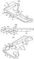
まず、コインホッパ100の概要が図1を参照して説明される。
本実施例において単にコイン102というときは大径コイン102L及び小径コイン102Sを含んでいる。
コインホッパ100は、バラ積み状態で保留された円板形のコイン102を一つずつ払い出す機能を有する。
コインホッパ100は、少なくともフレーム104、ホッパベース106、コイン保留ボウル108、回転ディスク110、コイン102の周方向案内装置112、弾出装置114、出口通路116、コイン検知装置118、出口通路画定装置122を含んでいる。
First, an outline of the coin hopper 100 will be described with reference to FIG.
In this embodiment, the
The coin hopper 100 has a function of paying out the disk-
The coin hopper 100 includes at least a frame 104, a
まずフレーム104が図1を参照して説明される。
フレーム104はホッパベース106及び保留ボウル108を支持する機能を有し、樹脂にて射出成型された断面矩形の筒状をしている。
フレーム104は、下端のベース124、及び、ベース124に一体化され上向きに延びる矩形筒形のサポート部126を含んでいる。
サポート部126の中空部には、制御基板や回転ディスク110の駆動のための電気モータ等が配置され、頭部は斜めに形成されている。
First, the frame 104 will be described with reference to FIG.
The frame 104 has a function of supporting the
The frame 104 includes a base 124 at a lower end and a rectangular cylindrical support portion 126 that is integrated with the base 124 and extends upward.
In the hollow portion of the support portion 126, an electric motor and the like for driving the control board and the rotating
次にホッパベース106が図2〜図4を参照して説明される。
ホッパベース106は、保留ボウル108、回転ディスク110、周方向案内装置112、弾出装置114、及びコイン検知装置118を所定の位置に保持する機能、及び、回転ディスク110によって移動されるコイン102を案内する機能を有する。
ホッパベース106は、矩形の厚板状を呈し、サポート部126の頂部に固定されている。
換言すれば、ホッパベース106は、所定の角度で傾斜している。
Next, the
The
The
In other words, the
ホッパベース106は上面128の中央に位置する有底かつ円形鍋形のガイド穴132、上下端部に形成した保留ボウル108の第1取付部134A、134B及び第2取付部136A、136B、ガイド穴132の周面の一部を開口した出口開口138、裏面側にコイン検知装置118の第3取付部140及び周方向案内装置112の第4取付部142(図6参照)を含んでいる。
ガイド穴132の底面144は、大凡平面であり、中央に、回転ディスク110を取り付ける回転軸146が貫通する軸孔147が形成されている。
ガイド穴132の周壁150は、C形の金属製ガイドリング148の内周面及び後述のガイド体196の第1側面208によって構成される。
底面144は後述のように本実施例では金属板258の上面によって構成されるが、ホッパベース106と一体に樹脂成形することができる。
回転ディスク110によって押動されるコイン102は、その下面がガイド穴132の底面144上を滑りつつ、かつ、その周面がガイド穴132の周面である周壁150に案内されつつ移動する。
出口開口138に臨んで後述の弾出装置114が配置されている。
The
A
The
As will be described later, the
The
A later-described ejection device 114 is arranged facing the
次に、保留ボウル108が図1を参照して説明される。
保留ボウル108は、コイン102をバラ済み状態に貯留する機能を有する。
保留ボウル108の下端部152は、ガイド穴132とほぼ同一径の円筒状であって、ホッパベース106に対し直交方向に延びている。
換言すれば、下端部152は斜め上方に向かって伸びており、その上端部154は四角形状に拡大する上端部154が形成され、上端はコイン102を投入するための上部開口156になっている。
下端部152の円筒内の底孔158に回転ディスク110の上部が配置されている。
保留ボウル108の上端部154と下端部152は傾斜壁によって接続され、その上に乗ったコイン102は、重力によって自然滑落し、下方の回転ディスク110上に落下する。
第1取付部134A、134B及び第2取付部136A、136Bに保留ボウル108の下部に形成した係止部(図示せず)を係止することにより、保留ボウル108を簡単操作でホッパベース106に取付け、取外しできるようにしてある。
Next, the storage bowl 108 will be described with reference to FIG.
The holding bowl 108 has a function of storing the
The lower end portion 152 of the storage bowl 108 has a cylindrical shape having substantially the same diameter as the
In other words, the lower end portion 152 extends obliquely upward, the upper end portion 154 is formed with an upper end portion 154 that expands in a square shape, and the upper end is an upper opening 156 for inserting
An upper portion of the
The upper end 154 and the lower end 152 of the storage bowl 108 are connected by an inclined wall, and the
The retaining bowl 108 can be easily attached to the
次に回転ディスク110が図2及び図5を参照して説明する。
回転ディスク110は、保留ボウル108にバラ積み状態に保留されるコイン102を一つずつ区分けし、弾出装置114に搬送する機能を有する。
回転ディスク110は、電気モータ162(図6参照)によって減速機164を介して回転駆動される。
回転ディスク110には、回転軸線Cを中心とする所定半径の円上であって等間隔に円形の通孔166が形成され、通孔166の上面側は、下向き錐形の導入部168が形成されている。
通孔166は、大径コイン102L又は小径コイン102Sが使用された場合であっても、回転ディスク110を交換せずとも良いよう、大径コイン102Lよりも僅かに大きく形成されている。
また、中央部には円錐形であって、かつ、回転軸146を取付けると共にコイン102の攪拌のための中央凸部172が形成されている。
回転ディスク110は、その下部がガイド穴132内にその周面が周壁150に対しコイン102の厚みよりも狭い間隔で、また、その上部は保留ボウル108の下端部152の底孔158内に僅かな隙間を空けて配置されている。
Next, the
The
The
On the
The through-
Further, a conical shape is formed at the central portion, and a central
The
回転ディスク110の裏面160である通孔166を区画するリブ170の下面には、コイン102を押し出すための第1押動部174及び第2押動部176が通孔166のそれぞれに相対して下向きに突出形成されている。
第1押動部174及び第2押動部176の第1押出面174A、及び第2押出面176A(図5参照)は、回転ディスク110の中心部から伸びるインボリュート曲線上に位置している。
第1押動部174と第2押動部176との間には、後述の周方向案内装置112を構成する第1規制体112A通過のための第1溝178A及び、第2規制体112B通過のための第2溝178Bが形成されている。
A first pushing
The first push out
Between the first pushing
回転ディスク110が回転した場合、その上に載っているコイン102は通孔166、中央凸部172等によって攪拌され、姿勢が変化させられて通孔166に落下する。
落下したコイン102の下面はガイド穴132の底面144に、外周は周壁150によって案内される。
そして、回転ディスク110の回転によって第1押出面174A及び第2押出面176Aによって押動されて回転ディスク110と共に連れ回りされる。
このとき、コイン102の周面は周壁150に案内されるが、周壁150に対する接触圧は殆どが遠心力に基づくものであるので大きな接触圧ではない。
連れ回り過程において、周方向案内装置112の第1規制体112A、及び第2規制体112Bによって連れ回りを阻止されたコイン102は、回転ディスク110の周方向へ案内され、最終的に第2押出面176Aによって、出口開口138へ押し込まれる。
When the
The lower surface of the dropped
Then, the
At this time, the peripheral surface of the
In the follow-up process, the
次に周方向案内装置112が図4を参照して説明される。
周方向案内装置112は、第1押動部174、第2押動部176によって押動されるコイン102を、回転ディスク110の周方向に案内し、出口開口138に誘導する機能を有する。
具体的には、ホッパベース106を下側から上側に貫通し、回転ディスク110の裏面160に向かって伸びる円柱ピン状の第1規制体112A及び第2規制体112Bが配置されている。
換言すれば、第1規制体112A及び第2規制体112Bはコイン102の移動経路182に突出している。
Next, the
The circumferential
Specifically, cylindrical pin-shaped first restricting
In other words, the first restricting
第1規制体112A及び第2規制体112Bは、ホッパベース106の裏面の第4取付部142に一端を固定された板バネ184A、184B(図6参照)に固定されている。
これにより、第1押動部174、第2押動部176によって押動されるコイン102は第1規制体112A及び第2規制体112Bによって回転ディスク110による連れ回りを阻止され、出口開口138側へ強制的に案内される。
なお、第1規制体112A又は第2規制体112Bの一方のみ、若しくは第1規制体112A及び第2規制体112Bを用いずともコイン102が出口開口138に自ずと移動する場合、それらを配置する必要はない。
The first restricting
As a result, the
In addition, when the
換言すれば、回転ディスク110の直径が大きく、第1押動部174及び第2押動部176によってコイン102を回転ディスク110の周方向へ誘導できる場合、第1規制体112A及び第2規制体112Bを配置する必要は無い。
第1規制体112A及び第2規制体112Bがコイン102から所定の横方向の力を受けた場合、板バネ184A、184Bが弾性変形して第1規制体112A及び第2規制体112Bは底面144の下方に向かって移動可能であり、コイン102がそれを乗り越えて移動可能になり、回転ディスク110と共に移動できる。
In other words, when the diameter of the
When the first restricting
次に出口開口138が図4を参照して説明される。
出口開口138は、周方向案内装置112の側方のガイド穴132の周壁150が所定長にわたって切除された矩形の開口である。
実施例においては、第1ガイド188及び第2ガイド192によってコイン102の出口が画定されるので、これらの間が出口開口138である。
出口開口138の長さ(ガイド穴132の周方向の長さ)は、コイン102が通過するに十分な長さである。
換言すれば、出口開口138はコイン102の直径よりも横方向の長さが僅かに大きく形成さている。
Next, the
The
In the embodiment, since the exit of the
The length of the outlet opening 138 (the circumferential length of the guide hole 132) is sufficient for the
In other words, the
次に弾出装置114を図4及び図6を参照して説明する。
弾出装置114は、回転ディスク110によって一枚ずつ区分けされて送り出されるコイン102をひとつずつ弾き出す機能を有する。
弾出装置114は、第1ガイド188、第2ガイド192及び付勢手段194を含んでいる。
Next, the ejecting device 114 will be described with reference to FIGS.
The ejecting device 114 has a function of ejecting the
The ejecting device 114 includes a first guide 188, a
まず第1ガイド188が図4を参照して説明される。
第1ガイド188は、コイン102が弾き出される際、出口開口138の一側を固定的に画定する機能を有する。
さらに、本実施例においては、コイン102として小径コイン102S又は大径コイン102Lの何れが使用される場合であっても、第2ガイド192の移動量が同一になるようにする機能を有する。
本実施例における第1ガイド188は、へら状の板金製ガイド体196の弧状端部198によって構成されている。
ガイド体196は他端部202及び側部凸部204が形成され、ホッパベース106に形成された弧状凹部207に側部凸部204が嵌り、かつ、他端部202がガイドリング148の一端の凹部206に接した状態において、小径コイン102Sに適した第1位置P1に位置するよう設定されている。
この状態において、直線状の第1側面208はガイド穴132の一部を構成する。
鎖線で示すように、ガイド体196を表裏反転した場合、第1側面208の反対側の第2側面212がガイド穴132の一部を構成する。
このとき、第1側面208はホッパベース106の端部に立設する垂立壁210に、及び他端部202がガイドリング148の凹部214に係合することにより位置決めされる。
第2側面212は、第1側面208よりも湾曲しており、ガイド穴132を大きくしている。
換言すれば、大径コイン102Lが第1規制体112A、第2規制体112Bによって出口開口138へ案内され、かつ、第2ガイド192が小径コイン102Sが弾き出される場合と同一の移動量になるよう設定されている。
First, the first guide 188 will be described with reference to FIG.
The first guide 188 has a function of fixedly defining one side of the
Further, in the present embodiment, the
The first guide 188 in this embodiment is constituted by an
The
In this state, the linear
As indicated by the chain line, when the
At this time, the
The
In other words, the large coin 102L is guided to the
次に第2ガイド192が図4及び図6を参照して説明される。
第2ガイド192は移動可能に設けられ、第1ガイド188との間でコイン102を挟んで弾き出す機能を有する。
第2ガイド192は、本実施例では支軸216に回転自在に支持されたローラ218である。
第2ガイド192は、回転ディスク110及び第1ガイド188の側方に配置され、出口開口138の一側壁を構成している。
Next, the
The
The
The
支軸216は、ホッパベース106の裏面に下向きに固定された固定軸222にピボット運動可能に取り付けられた揺動レバー224の一端部に固定され、ホッパベース106の弧状長孔226を通って出口開口138に隣接し、かつ第1ガイド188に対し所定距離離れた出口通路116に位置している。
The
次に付勢手段194が図6を参照して説明される。
付勢手段194は、第2ガイド192を第1ガイド188に弾性的に近づける機能を有している。
ホッパベース106の下面に突出するピン228と揺動レバー224から下方に突出する支軸216との間に掛止めした付勢手段194、具体的にはスプリング232が掛止され、ローラ218が第1ガイド188に近づくよう図4において反時計方向(図6において時計方向)に付勢されている。
通常、揺動レバー224は一体に形成された被係止部234が、ホッパベース106の裏面に形成された表面が弾性的に形成された係止部236によって係止されることにより、第1ガイド188に対しコイン102の直径よりも小さい間隔で停止された待機位置SPにおいて静止している。
係止部236は、例えばホッパベース106の裏面に突出するピンに外装したゴムリング238である。
係止部236を弾性体により構成することにより、揺動レバー224のバウンドを抑制し、コイン検知装置118が誤検知することを防止できる。
Next, the biasing means 194 will be described with reference to FIG.
The urging means 194 has a function of elastically bringing the
A biasing means 194, specifically a
Usually, the rocking
The locking
By configuring the locking
小径コイン102S又は大径コイン102Lの直径部が第1ガイド188と第2ガイド192との間に進行した場合、図4に鎖線示するように第2ガイド192が弾き出し位置DPに移動された後、スプリング232の弾発力でコイン102を出口通路116へ弾き出す。
なお、第2ガイド192は揺動レバー224によってピボット運動を行うが、直線運動により第1ガイド188に対し接近、離隔するよう変更することができる。
また、付勢手段194は、スプリングの他、電磁アクチュエータ、空気アクチュエータ等同様の機能を有する装置に変更することができる。
When the diameter portion of the small coin 102S or the large coin 102L advances between the first guide 188 and the
The
Further, the urging means 194 can be changed to a device having a similar function such as an electromagnetic actuator and an air actuator in addition to the spring.
次にコイン検知装置118が図4及び図6を参照して説明される。
コイン検知装置118は、コイン102による第2ガイド192の移動を直接的又は間接的に検知して検知信号DSを出力する機能を有する。
実施例のコイン検知装置118は、第2ガイド192、第2ガイド192を支持する揺動レバー224、揺動レバー224と一体的に移動する作用片242及び作用片242の検知装置244を含んでいる。
Next, the
The
The
作用片242は、揺動レバー224と一体に、第2ガイド192よりも支軸216から遠い位置に形成され、固定軸222を中心とする円弧状に所定の長さで延在する被検知部246である。
検知装置244は、被検知部246を検知した場合、「H」又は「L」の電気的な検知信号DSを出力する機能を有する。
実施例の検知装置244は、透過形の光電センサ248であり、透孔248Hから投光される投射光が遮断された場合、検知信号DSを出力する。
光電センサ248は、ホッパベース106の裏面の第3取付部140に取付ブラケット250を介して固定されている。
The
The
The
The
実施例において光電センサ248はサポート部126で囲われたホッパベース106の下方に位置するので、外部から不正にアクセスすることが極めて困難である。
コイン102によって第2ガイド192が弾き出し位置DPへ移動された場合、図4において鎖線で示すように被検知部246が透孔248Hに相対する場合、透孔248Hから受光部への投射光を遮断する。
この遮断によって、光電センサ248の出力は「H」から「L」になる。
第2ガイド192が弾き出し位置DPから待機位置SPへ移動する場合、移動途上において被検知部246が透孔248Hから外れるので、光電センサ248の出力は「L」から「H」になる。
光電センサ248の出力が「L」から「H」に変化したときに検知信号DSを出力する。
この検知信号DSをカウントすることにより、払い出したコイン102の数を知ることができる。
したがって、検知装置244は、同様の機能を有する他の方式、例えば反射式光電センサ、金属センサ等他のセンサに変更することができる。
さらに、揺動レバー224または第2ガイド192の移動を直接検知することによりコイン検知装置118を構成することができる。
In the embodiment, since the
When the
By this interruption, the output of the
When the
When the output of the
By counting this detection signal DS, the number of
Therefore, the
Furthermore, the
次に出口通路116が図4を参照して説明される。
出口通路116は、弾出装置114によって弾き出されたコイン102を案内する機能を有する。
出口通路116は、出口開口138に連続して回転ディスク110の周方向に伸びる薄板状の通路である。
出口通路116は、ホッパベース106に形成された凹溝252、第1ガイド188、第2ガイド192及び凹溝252の上側解放面を覆う出口通路画定ガイド254によって画定され、回転ディスク110の周方向に伸びている。
凹溝252の底面256は、ガイド穴132の底面144と同一平面内に配置され、弾出装置114によって弾き出されたコイン102の下面が案内される。
底面144は、ガイド穴132の形状に形成した金属(ステンレス)板258の上面である。
底面144を導電性の金属板にすることにより」、樹脂製の回転ディスク110とコイン102との摩擦によって発生した静電気を、この底面144を介してアースすることができるので、静電気による電子部品等の破損等の問題を解消できる利点がある。
出口通路画定装置122は、本実施例においてはホッパベース106及び出口通路画定ガイド254により構成される。
Next, the
The
The
The
The
The
By making the bottom surface 144 a conductive metal plate ", static electricity generated by friction between the resin
The outlet passage defining device 122 is constituted by a
次に第1ガイド188の仮位置決め装置259を説明する。
仮位置決め装置259はガイド体196を第1位置P1又は第2位置P2に仮決めする機能を有し、ダボ孔260、262及びダボ264を含んでいる。
第1ガイド188には、第1位置P1への位置決め用のダボ孔260及び第2位置P2への位置決め用のダボ孔262が形成されている。ダボ孔260及び262は所定直径の円形をしている。
ダボ孔260、262に嵌合可能に底面256に円柱状のダボ264が突出形成されている。
ダボ264にダボ孔262が嵌合し、他端部202が凹部206に係合し、かつ側部凸部204が凹部207に係合した場合、弧状端部198は第1位置P1に位置されるよう設定されている。
また、ガイド体196を表裏ひっくり返し、ダボ孔260をダボ264に嵌合し、他端部202を凹部214に係合させた場合、端部198が第2位置P2になるよう設定されている。
Next, the
The
The first guide 188 has a
A
When the
Further, when the
次に出口通路画定装置122が図1〜4及び図7〜11を参照して説明される。
出口通路画定装置122は、出口通路116を画定する機能を有する。
出口通路116は、ホッパベース106の凹溝252に出口通路画定ガイド254を嵌め込んだ後、スクリュウ等の固定手段280によってホッパベース106に固定することにより画定形成される。
凹溝252は、図4において、ガイド穴132の上端部から中央の範囲で横方向に延びる通路であり、その底面256はガイド穴132の底面144と同一の仮想平面内に配置されている。
具体的には、ガイド穴132の底面144を形成する金属板258がホッパベース106の左端部まで延長されている。
そして、当該金属板258の上に第1ガイド188を構成するガイド体196が固定され、第2ガイド192と共に出口開口138を構成する。
図10に示すように凹溝252の上側の側壁268は、垂立面270と下向き斜面272とが交互に形成されている。
凹溝252の下側の側壁274は、ガイド穴132側へ向かって傾斜する斜面であって、底面256に対し直角上方へ延びて形成されている。
The outlet passage defining device 122 will now be described with reference to FIGS. 1-4 and 7-11.
The outlet passage defining device 122 has a function of defining the
The
In FIG. 4, the
Specifically, the
Then, a
As shown in FIG. 10, on the
The
次に出口通路画定ガイド254が説明される。
出口通路画定ガイド254は、平板状であって、平面視倒立L形に透明樹脂で成形されている。
ガイド体196が小径コイン102Sに対応する第1位置P1に設定されているか、大径コイン102Lに対応する第2位置P2に設定されているかの確認及び出口通路116におけるコイン102の移動状況を確認可能にするためである。
出口通路画定ガイド254のガイド穴側側面276は、回転ディスク110の周縁にコイン102の厚み未満の距離で隣接するよう回転軸146の軸心を中心とする円弧に形成され、対面する直状側面278はホッパベース106に固定された場合、ホッパベース106の左側面282と面一に配置される。
直状側面278にはホッパベース106と共にコインの出口284を構成する下向き凹部286が形成されている。
Next, the outlet
The outlet
Confirm that the
The guide hole
The
出口通路画定ガイド254の下面288は、平面であって、その上端部下面に棒状であって、断面矩形の上側側面ガイド290が突出形成されている。
上側側面ガイド290からコイン102の直径よりも僅かに離れた位置に出口画定突起292が下向きに形成されている。
上側側面ガイド290と出口画定突起292との突出量は同一であって、コイン102の厚みよりも僅かに高い(厚い)量H(図9)において形成されている。
換言すれば、直状側面278には上側側面ガイド290と出口画定突起292とによって下向き凹部286が形成されている。
下向き凹部286の中間には、直状側面278からガイド穴側側面276に向かって球状であって、大人の人指し指の先端が挿入できる程度の取り出し凹部296が形成されている。
下向き凹部286は、下面288の一部である上縁286A、上側側面ガイド290の側面である左端縁286L、及び出口画定突起292の側面である右側縁286Rによって構成され、取り出し凹部296は上縁286Aの中間に形成されている。
したがって、下向き凹部286に対応する下面288には直状側面278から出口開口138、換言すればガイド穴132に向かって所定長さで球面状に窪み、また、取り出し凹部296の上側側面ガイド290側の左上縁286ALは左側縁286L側までの間の所定の長さW1において直線状に形成され、出口画定突起292側の右側縁286Rまでの間の右上縁286ARは所定長さW2において直線状に形成されている。
取り出し凹部296の窪み形状は球面状でなくとも、ピンセット状器具又は指先によってコイン102を取り出すことができるよう窪んでいればよい。
A
An
The amount of projection of the
In other words, a downward
In the middle of the
Accordingly, the outlet opening 138 from the
The recess shape of the take-out
出口通路画定ガイド254の上側側面から所定の幅で係止突起294が突出している。
係止突起294には前記垂立面270及び下向き斜面272に相対して垂立面298及び斜面300が階段状に形成されている。
係止突起294の上端部の上面302は下面288と平行に形成され、ホッパベース106に形成された係止突起294の幅よりも僅かに大きい幅を有する係止凹部308(図4参照)に係合可能である。
上面302と上側側面ガイド290の下端との距離H1は、上側側面ガイド290の下端304が当接する底面256と係止凹部308の下面との間の距離H2(図10)よりも僅かに大きく形成されている。
係止突起294が密に保持されるので出口通路画定ガイド254が振動することがなく、コイン102の払い出しに悪影響を及ぼさないからである。
A locking
A vertical surface 298 and a
The
The distance H1 between the
This is because the locking
次に出口通路画定ガイド254をホッパベース106に固定する作業を説明する。
係止突起294を係止凹部308に挿入し、上側側面ガイド290の下端304を底面256に押し付けた状態で出口通路画定ガイド254の下端部を下方へ押し下げる。
この後、下面288をガイド体196の上面に押し付けた状態で固定手段280としてのスクリュウ312A、312Bを貫通孔314A、314Bを貫通させて底面256を構成する金属板258に形成したネジ孔316A、316Bにねじ込んで固定する。
ガイド体196はコイン102の厚みよりも僅かに厚く形成されているので、下面288は底面256と大凡平行になる。
また、上側側面ガイド290の下端304と出口画定突起292の下端304が底面256の表面に密接し、厚みがコイン102の厚みよりも僅かに大きく、かつ横幅がコイン102の直径よりも僅かに大きい出口284がホッパベース106の左側面282に形成される。
これにより、底面256、出口通路画定ガイド254の下面288、及び上側側面ガイド290並びに出口画定突起292、及び第1ガイド188によって扁平な平板状に画定され、出口開口138から出口284に向かって直線的に延びる出口通路116が画定形成される。
Next, an operation for fixing the outlet
The locking
Thereafter, screw
Since the
Further, the
Thus, the flat surface is defined by the
図9に示すように、出口284において取り出し凹部296の左側には幅W1において底面256と平行な左上縁286AL、右側には幅W2において底面256と平行な右上縁286ARが位置する。
また取り出し凹部296よりも出口開口138側は左上縁286AL及び右上縁286ARが連続した上縁286Aによって構成される。
出口通路116の下縁286Uは底面256によって構成される。
換言すれば、出口通路116の左右(図4においては上下)にはその全長にわたってコイン102の厚みよりも僅かに厚い通路が連続的に構成されている。
したがって、出口通路116を出口開口138から出口284に向かって移動するコイン102はその両端部を底面256と左上縁286AL又は右上縁286ARによって案内されるので、コイン102の移動姿勢は安定する。
結果として、コイン102の出口284からの払い出し方向が安定するという利点がある。
また、出口284の上側中間には取り出し凹部296によって出口284から出口開口138側へ所定の長さで出口通路116の上側に位置する窪みが形成される。
図8(C)において、下面288の取り出し凹部296に相対するガイド穴側側面276から内方へ延びる溝318は第2ガイド192の頭部が移動するための溝である。
As shown in FIG. 9, an upper left edge 286AL parallel to the
Further, the
The lower edge 286U of the
In other words, a passage that is slightly thicker than the thickness of the
Therefore, since the
As a result, there is an advantage that the payout direction of the
In addition, a recess located on the upper side of the
In FIG. 8C, a
出口通路画定ガイド254が正常にホッパベース106に固定され、かつコイン102が出口通路116に滞留した場合、コイン102の先端が出口284と大凡面一に位置する(図4鎖線示)。
コイン102が出口通路116に滞留している場合、指先を取り出し凹部296に挿入すると、指先がコイン102の上面に僅かに接触するのでコイン102を指先で押し下げて適度の摩擦力をもって引き出すように移動させることにより、コイン102を出口通路116から引き出すことができる。
When the outlet
When the
次に、出口通路画定ガイド254の位置決め装置322を説明する。
位置決め装置322は、出口通路画定ガイド254を第1位置P1若しくは第2位置P2に位置決めする機能を有し、ベースダボ264、出口通路画定ガイドダボ326及びガイド体196に穿孔されたダボ孔260、262を含んでいる。
ベースダボ264は仮位置決め装置259と共用である。
前記したように、ガイド体196の他端部202が凹部206に、側部凸部204が凹部206に係合し、かつベースダボ324がダボ孔260に嵌合した状態において、ガイド体196は第1ガイド188の第1位置P1に位置決めされるように、ガイド体196の他端部202が凹部214に、かつベースダボ324がダボ孔262に嵌合した状態において、ガイド体196は第1ガイド188の第2位置P2に位置決めされるようにそれぞれ設定されている。
Next, the
The
The
As described above, in the state where the
出口通路画定ガイドダボ326は下面288に突出形成された円柱状の突起であって、ベースダボ264がダボ孔260に嵌合した場合ダボ孔260に嵌合し、ベースダボ324がダボ孔262に嵌合した場合ダボ孔262に嵌合するように位置が設定されている。
この構成により、出口通路画定ガイド254の係止突起294を係止凹部308に係合した状態で、出口通路画定ガイド254を底面256に近づけた場合、ベースダボ264に嵌合しているガイド体196のダボ孔260又は262に、出口通路画定ガイドダボ326が進行でき、自動的に出口通路画定ガイド254の位置だしが行われる。
この状態において、出口通路画定ガイドダボ326の貫通孔314A、314Bがガイド体196の貫通孔212A。212Bに相対する。
よって、これらに固定用スクリュウ312A、312Bを貫通させて金属板258のネジ孔316A、316Bにそれぞれねじ込むことにより出口通路画定ガイド254及びガイド体196は所定位置に位置決めされと共に固定される。
ガイド体196が第2位置P2にある場合、貫通孔314Cがガイド体196の貫通孔212Aに相対するのでスクリュウ312Aはこれらを貫通してネジ孔316Cにねじ込まれることができる。
この状態におて貫通孔314Bは貫通孔212Cに相対し、スクリュウ312Bはこれらを貫通してネジ孔316Bにねじ込まれる。
The exit passage defining
With this configuration, when the exit
In this state, the through
Therefore, the outlet
When the
Contact through
図9に示すように、出口通路画定ガイド254が正規の位置に固定された場合、出口通路116はその高さがコイン102の厚みよりも僅かに大きいHの厚みを有し、かつ幅Wがコイン102の直径よりも僅かに大きい断面が扁平横長矩形の通路に形成され、出口284も同じ大きさに形成される。
出口284の中間には前述のように出口284からガイド穴132側に向かって所定長さで取り出し凹部296が形成されるので、取り出し凹部296が形成された部分は出口通路画定ガイド254の下面288が存在しない。
換言すれば、上側側面ガイド290の左側縁286Lから取り出し凹部296の端部までの距離W1は、Hの距離離れて上縁と下縁が位置する。
相対する他端部の出口画定突起292の右側縁286Rから距離W2の間は上縁及び下縁がHの距離離れて平行に配置される。
さらに換言すれば、コイン102の左右端は、下縁286Uと上縁186Aとによって案内されつつ移動する。
したがって、コイン102の払出姿勢は安定する。
As shown in FIG. 9, when the outlet
In the middle of the outlet 284, the
In other words, the distance W1 from the
Between the
In other words, the left and right ends of the
Therefore, the payout posture of the
次にコインサイズ表示装置332を説明する。
コインサイズ表示装置332はガイド体196の第1ガイド188が第1位置P1に位置しているのか、第2位置P2に位置しているのかを直接的又は間接的に表示する機能を有する。
具体的には、ガイド体196の固定手段280の固定位置によって出口284の近傍位置に配置した表示体336に設定コインを表示する機能を有する。
表示部336の表示内容としては、設定されたコインサイズ、換言すればコインの直径を表示することが好ましい。
直感的に使用されているコインサイズを直接的に理解できるからである。
しかし、第1位置又は第2位置のように間接的に表示することもできる。
また、表示位置は出口284の近傍であるので、本実施例のように出口284と同じ仮想面内に並列配置する他、出口284に対し直角位置である出口通路画定ガイド254の上面に配置することもできる。
Next, the coin size display device 332 will be described.
The coin size display device 332 has a function of directly or indirectly displaying whether the first guide 188 of the
Specifically, it has a function of displaying the set coin on the
As the display content of the
This is because the coin size used intuitively can be directly understood.
However, it is also possible to display indirectly such as the first position or the second position.
Further, since the display position is in the vicinity of the outlet 284, the display position is arranged in parallel in the same virtual plane as the outlet 284 as in the present embodiment, and is also arranged on the upper surface of the outlet
実施例のコインサイズ表示装置332は、大凡T形の表示体336によって構成される。
表示体336のT形の横向き部338は断面矩形であって、正確には中間に段差342が形成されている。
横向き部338の一端面である第1端面344にはガイド体196が第1位置P1に位置した場合、最適のコインサイズ(直径)の第1表示部346を設ける。例えば、直径26ミリに相当する「26」を浮き文字又は窪み文字状に成形し、第1表示部346を構成する。浮き文字等に代えて数字を印刷したシールを貼付することができる。
また、第1端面344が後述の表示窓364に位置する場合、表示体336の上面にも第1端面344と同一のコインサイズを表示する上面第1表示部348を設けることが好ましい。
コインホッパ100を上方から見下ろした場合、コインサイズを容易に確認できるからである。
The coin size display device 332 of the embodiment is constituted by a roughly T-shaped
The T-shaped lateral portion 338 of the
When the
In addition, when the first end surface 344 is positioned in a
This is because the coin size can be easily confirmed when the coin hopper 100 is looked down from above.
横向き部338の他端面である第2端面352にはガイド体196が第2位置P2に位置した場合、最適のコインサイズ、例えば直径30ミリに相当する「30」を浮き文字状等に成形し、第2表示部354を構成する。
第2表示部354が表示窓364に位置する場合、表示体336の上面にも第2端面352と同一のコインサイズを表示する上面第2表示部354を設けることが好ましい。
表示体336の横向き部338に対し直角をなす断面矩形の縦向き部358の端部に円形の貫通孔362が形成されている。
第1端面344が表示窓364に位置する場合、貫通孔362は貫通孔314Aに相対可能に形成され、第2端面352が表示窓364に位置する場合、貫通孔362は貫通孔314Cに相対可能に形成されている。
第1表示部346及び第2表示部354は、出口通路画定ガイド254の側面278に形成した矩形の表示窓364に嵌合した場合、前記固定位置に位置決めされるように設定することが好ましい。
出口284を正面から見た場合、設定されているコインサイズが容易に確認できるからである。
表示体336は、出口通路画定ガイド254の上側に宛われ、スクリュウ312Aによって出口通路画定ガイド254と共締めされることにより固定される。
When the
When the second display unit 354 is positioned in the
A circular through-hole 362 is formed at the end of the vertical portion 358 having a rectangular cross section that is perpendicular to the horizontal portion 338 of the
When the first end surface 344 is located in the
The first display unit 346 and the second display unit 354 are preferably set so as to be positioned at the fixed position when fitted into the
This is because when the exit 284 is viewed from the front, the set coin size can be easily confirmed.
The
次に実施例の作用を説明する。
まず、小径コイン102S(直径25ミリ)に適した仕様に設定する作業を説明する。
ガイド体196は、他端部202が凹部206に、側部凸部204が凹部207に係合し、かつダボ孔260がベースダボ264に嵌合した第1位置P1に設置される。
換言すれば、出口通路画定ガイドダボ326がダボ孔260に嵌合して出口通路画定ガイド254の位置決めが自動的に行われる。
次に出口通路画定ガイド254の上端部の係止突起294をホッパベース106の係止凹部308に係合した後、下端部をホッパベース106に近づけ、下面288をガイド体196の上面に密着させる。
このとき出口通路画定ガイドダボ326は、ダボ孔260に嵌合する。
この状態において、ガイド体196の貫通孔212Aと出口通路画定ガイド254の貫通孔314A、貫通孔212Bと貫通孔314Bとが大凡重なりあう。
続いて表示体336の第1表示部346側の横向き部338の先端を表示窓364に挿入し、貫通孔362を貫通孔314Aに重ね合わせる。
この状態で、スクリュウ312Aを貫通孔362及び314Aに貫通し、スクリュウ312Bを貫通孔314Bを貫通させてネジ孔316A、316Bにそれぞれねじ込み、ガイド体196、出口通路画定ガイド254及び表示体336を固定する。
これにより、ガイド体196は第1位置P1に固定され、上側側面ガイド290、出口画定突起292、底面256及び下面288によって小径コイン102Sの直径及び厚みよりも僅かに大きい横長矩形の出口通路116がホッパベース106の側面に画定形成される。
Next, the operation of the embodiment will be described.
First, an operation for setting a specification suitable for the small-diameter coin 102S (diameter 25 mm) will be described.
The
In other words, the outlet passage defining
Next, after engaging the locking
At this time, the outlet passage defining
In this state, the through-
Subsequently, the tip of the horizontal portion 338 on the first display portion 346 side of the
In this state, the
As a result, the
コイン102の払出指示信号を受けた場合、電気モータ162が回転し、減速機164及び回転軸146を介して回転ディスク110が図2において時計方向に回転される。
回転ディスク110の回転により、小径コイン102Sは通孔166に落下し、その下面はガイド穴132の底面144に支えられる。
さらに、小径コイン102Sは第1押動部174(第1押出面174A)及び第2押動部176(第2押出面176A)により押されてその下面は底面144上を滑り、かつ、周面は周壁150に案内されつつ回転ディスク110と共に連れ回りされる。
このとき、小径コイン102Sは第2押動部176によりその外向き円弧面を押されるので小径コイン102Sを回転中心側に押す力を受け、回転による遠心力が小径コイン102Sに作用するものの周壁150、及び第1側面208との接触圧力はほぼゼロの状態で移動する(図3)。
When the
Due to the rotation of the
Further, the small-diameter coin 102S is pushed by the first pushing portion 174 (first pushing
At this time, since the small-diameter coin 102S is pushed by the second pushing
小径コイン102Sは、自ら又は規制体112A、112Bによって回転ディスク110の周方向に案内される。
このとき、規制体112A、112Bには横方向から力が加わるが、底面144に対しほぼ垂直状態を保つ。
小径コイン102Sの周方向への移動により、小径コイン102Sは第1ガイド188と第2ガイド192との間に達する(図4鎖線示)。
第2ガイド192は、小径コイン102Sによって移動されるまで待機位置SPに位置する。
光電センサ248は、第2ガイド192が待機位置SP近傍に位置する場合、検知信号DSを出力しない。
The small-diameter coin 102S is guided in the circumferential direction of the
At this time, a force is applied to the regulating
Due to the movement of the small-diameter coin 102S in the circumferential direction, the small-diameter coin 102S reaches between the first guide 188 and the second guide 192 (shown by a chain line in FIG. 4).
The
The
小径コイン102Sは、第1押動部174に引き続いて第2押動部176によってさらに周方向へ押され、かつ、第1ガイド188は固定であるので、第2ガイド192が小径コイン102Sによって待機位置SPから弾き出し位置DPへ移動される(図4鎖線示)。
これにより、揺動レバー224が固定軸222を中心に時計方向へ回動される。
この弾き出し位置DPへ移動する途上において、作用片242は透孔248Hに相対し、投光部からの投射光を遮断するため、光電センサ248の出力は「H」から「L」に変化する。
図13に示すように、図示しない制御装置は出力が「H」から「L」に変化した時点から時間Tの計時を開始する。
The small-diameter coin 102S is pushed further in the circumferential direction by the second pushing
As a result, the
In the middle of moving to the ejection position DP, the
As shown in FIG. 13, the control device (not shown) starts measuring time T from the time when the output changes from “H” to “L”.
小径コイン102Sは、その直径部が第1ガイド188と第2ガイド192との間を通過した直後に付勢手段194の弾発力によって第2ガイド192を介してほぼ横方向に弾き出され、出口通路116を通って出口284から払い出される。
これにより、第2ガイド192は待機位置SPに戻る。
The small-diameter coin 102S is ejected almost laterally through the
As a result, the
第2ガイド192の待機位置SPへの復帰動に連動して作用片242が光電センサ248の遮光を中断するので、透孔248Hからの投射光が受光部に受光されるようになる。
これにより、光電センサ248の出力は「L」から「H」に変化する。
この「L」から「H」への出力変化に基づいて検知装置244は検知信号DSを出力する。
したがって、この検知信号DSをカウントすることにより出口284から払い出されたコイン102の数を計数することができる。
また、「H」から「L」に変化した後、「L」の継続時間が所定時間よりも短い場合、異常信号は出力されない。
光電センサ248の出力「L」の継続時間が所定時間T、例えば通常の二倍以上継続した場合、異常状態であるとして異常信号ESを出力することができる。
例えば、「L」の継続時間がコインの2枚払出に要する時間を経過した場合、異常信号を出力し、これに基づいて電気モータ162の回転を停止することができる。
The
As a result, the output of the
Based on the output change from “L” to “H”, the
Therefore, by counting this detection signal DS, the number of
In addition, after changing from “H” to “L”, if the duration of “L” is shorter than the predetermined time, no abnormal signal is output.
When the duration of the output “L” of the
For example, when the time required for paying out two coins has elapsed for “L”, the abnormality signal is output, and based on this, the rotation of the
図11に示すように、小径コイン102Sが出口通路116に滞留した場合、小径コイン102Sの先端が大凡出口284において停止している。
この場合、指先を取り出し凹部296に挿入し、小径コイン102Sの上面を指先(爪先)で押して摩擦力を付与した後、指先を引き出す。
これにより、小径コイン102Sは指先との摩擦力によって引き出され、出口通路116から排除できる。
指先に代えてピンセットにてつまみ出すこともできる。
この場合、底面256側にも凹部を形成することにより掴みやすくなるので残留コインの除去を容易に行うことが出来る。
As shown in FIG. 11, when the small-diameter coin 102S stays in the
In this case, the fingertip is taken out and inserted into the
As a result, the small-diameter coin 102S is pulled out by the frictional force with the fingertip and can be removed from the
It can be picked up with tweezers instead of the fingertips.
In this case, since the concave portion is also formed on the
次に大径コイン102L(直径30ミリ)に適した仕様に変更する作業を説明する。
スクリュウ312A、312Bをゆるめ、出口通路画定ガイド254を取り外す。
次いでガイド体196を裏返して他端部202を凹部214に係合した状態でダボ孔262をベースダボ324に嵌合し、第2位置P2に仮位置決めする。
次に係止突起294をホッパベース106の係止凹部308に係合した後、下端部を金属板258に近づけ、下面288をガイド体196の上面に密着させる。
このとき出口通路画定ガイドダボ326がダボ孔260に嵌合し、出口通路画定ガイド254の位置だしが行われる。
この状態において、貫通孔314Cは金属板258のネジ孔316Cに重なり、314Bはガイド体196の貫通孔212Bに重なる。
次に表示体336の第2端面352側の横向き部338の先端を表示窓364に挿入し、貫通孔362を貫通孔314Cに重ね合わせる。
この状態で、スクリュウ312Aを貫通孔362及び314C、スクリュウ312Bを貫通孔314Bに貫通させてネジ孔316C、316Bにそれぞれねじ込み、ガイド体196、出口通路画定ガイド254及び表示体336を固定する。
Next, an operation for changing to a specification suitable for the large-diameter coin 102L (
The
Next, the
Next, after engaging the locking
At this time, the exit passage defining
In this state, the through
Next, the tip of the lateral portion 338 on the second end surface 352 side of the
In this state, the
大径コイン102Lが使用される場合も小径コイン102Sの場合と同様に、払い出される。
唯一変更され点は、第2位置P2に固定された第1ガイド188と第2ガイド192とによって、弾き出される点が異なる。
しかし、第2ガイド192の弾き出し位置DPは小径コイン102Sが使用される場合と変わらない。
したがって、大径コイン102Lが使用される場合も前述の小径コイン102Sが使用される場合と同様にコイン102と検知信号DSとは一対一の関係で払い出される。
また出口通路116に滞留した大径コイン102Lを引き出す場合も小径コイン102Sと同様に引き出すことができる。
When the large-diameter coin 102L is used, it is paid out as in the case of the small-diameter coin 102S.
The only change is that the first guide 188 and the
However, the ejection position DP of the
Therefore, even when the large-diameter coin 102L is used, the
Further, when the large-diameter coin 102L staying in the
102 コイン
108 コイン保留ボウル
110 回転ディスク
114 弾出装置
116 出口通路
156 上部開口
158 底孔
166 通孔
188 第1ガイド
192 第2ガイド
284 出口
286U 下縁
286L、286R 左右の側縁
286A 上縁
286AL、286AR 出口の短縁近傍の上縁
102 coins
108 coin holding bowl
110 Rotating disc
114 ejector
11 6 Exit passage
156 Top opening
158 Bottom hole
166 through hole
188 First Guide
192 Second Guide
284 Exit
286U lower edge
286L, 286 R left and right side edge
286A Upper edge
Upper edge near short edge of 286AL, 286AR exit
Claims (1)
前記出口通路(116)は下縁(286U)、左右の側縁(286L、286R)、及び上縁(286A)によって扁平な横長矩形に形成され、さらに前記出口(284)の短縁近傍の上縁(286AL、286AR)及び下縁はコイン厚みよりも僅かに大きな間隔(H)において平行に形成され、かつ前記出口(284)の長縁の少なくとも一方は外側に向かって窪む凹部(296)に形成され、かつ前記出口通路(116)の途中まで伸びていることを特徴とするコインホッパのコインの出口構造。 A coin (102) is divided one by one by a rotating disk (110) with a through hole (166) disposed in a bottom hole (158) of a coin holding bowl (108) having an upper opening (156), and the rotating disk A first guide (188) arranged in a fixed state on the side of (110) and a second guide (192) provided so as to be elastically attachable to and detachable from the first guide (188). In a coin hopper that throws out the coins (102) sorted by the device (114) into an outlet passage (116), and throws out laterally from an outlet (284) on an end surface of the outlet passage (116) ,
The outlet passage (116) is formed in a flat horizontally-oriented rectangle by a lower edge (286U), left and right side edges (286L, 286R), and an upper edge (286A), and further above the short edge of the outlet (284). The edges (286AL, 286AR) and the lower edge are formed in parallel at a distance (H) slightly larger than the coin thickness, and at least one of the long edges of the outlet (284) is recessed to the outside (296) A coin outlet structure for a coin hopper, characterized in that the coin outlet is extended to the middle of the outlet passage (116) .
Priority Applications (1)
| Application Number | Priority Date | Filing Date | Title |
|---|---|---|---|
| JP2009120036A JP5382511B2 (en) | 2009-05-18 | 2009-05-18 | Coin hopper coin exit structure |
Applications Claiming Priority (1)
| Application Number | Priority Date | Filing Date | Title |
|---|---|---|---|
| JP2009120036A JP5382511B2 (en) | 2009-05-18 | 2009-05-18 | Coin hopper coin exit structure |
Publications (3)
| Publication Number | Publication Date |
|---|---|
| JP2010267213A JP2010267213A (en) | 2010-11-25 |
| JP2010267213A5 true JP2010267213A5 (en) | 2012-06-21 |
| JP5382511B2 JP5382511B2 (en) | 2014-01-08 |
Family
ID=43364105
Family Applications (1)
| Application Number | Title | Priority Date | Filing Date |
|---|---|---|---|
| JP2009120036A Active JP5382511B2 (en) | 2009-05-18 | 2009-05-18 | Coin hopper coin exit structure |
Country Status (1)
| Country | Link |
|---|---|
| JP (1) | JP5382511B2 (en) |
Families Citing this family (3)
| Publication number | Priority date | Publication date | Assignee | Title |
|---|---|---|---|---|
| JP2016019561A (en) * | 2014-07-11 | 2016-02-04 | 株式会社オーイズミ | Game medium use machine |
| JP6404631B2 (en) * | 2014-08-07 | 2018-10-10 | 株式会社ニューギン | Game machine |
| JP6402312B2 (en) * | 2015-11-19 | 2018-10-10 | 旭精工株式会社 | Coin hopper and coin diameter judging method |
Family Cites Families (3)
| Publication number | Priority date | Publication date | Assignee | Title |
|---|---|---|---|---|
| JP4382203B2 (en) * | 1999-08-11 | 2009-12-09 | Juki株式会社 | Coin dispenser |
| JP3857841B2 (en) * | 1999-11-04 | 2006-12-13 | 三洋電機株式会社 | Coin dispenser |
| JP4686275B2 (en) * | 2005-07-01 | 2011-05-25 | 日立オムロンターミナルソリューションズ株式会社 | Automatic cash transaction equipment |
-
2009
- 2009-05-18 JP JP2009120036A patent/JP5382511B2/en active Active
Similar Documents
| Publication | Publication Date | Title |
|---|---|---|
| JP5066673B2 (en) | Coin hopper | |
| JP2008097322A5 (en) | ||
| JP2014146134A (en) | Coin dispensing device | |
| JP5382511B2 (en) | Coin hopper coin exit structure | |
| JP2010267213A5 (en) | ||
| JP5261656B2 (en) | Coin hopper | |
| JP5444564B2 (en) | Coin size display device for coin hopper | |
| JP2009230617A5 (en) | ||
| JP2007260322A (en) | Token dispensing device | |
| JP4711738B2 (en) | Disc hopper with fraud prevention device | |
| JP2011103064A5 (en) | ||
| JP5417587B2 (en) | Coin hopper | |
| JP5481627B2 (en) | Disc ejector | |
| JP5604705B2 (en) | Coin exit device for coin hopper | |
| JP5585020B2 (en) | Coin hopper | |
| JP5945752B2 (en) | Coin dispenser | |
| JP2016019561A (en) | Game medium use machine | |
| JP5789819B2 (en) | Coin hopper | |
| JP2010049671A5 (en) | ||
| JP2010131122A5 (en) | ||
| JP2011048800A5 (en) | ||
| JP5370737B2 (en) | Coin hopper | |
| JP4397232B2 (en) | Coin delivery device | |
| JP2014174720A5 (en) | ||
| JP2011034174A5 (en) |