JP5442760B2 - Static addressing of devices in dynamic routing networks - Google Patents
Static addressing of devices in dynamic routing networks Download PDFInfo
- Publication number
- JP5442760B2 JP5442760B2 JP2011540695A JP2011540695A JP5442760B2 JP 5442760 B2 JP5442760 B2 JP 5442760B2 JP 2011540695 A JP2011540695 A JP 2011540695A JP 2011540695 A JP2011540695 A JP 2011540695A JP 5442760 B2 JP5442760 B2 JP 5442760B2
- Authority
- JP
- Japan
- Prior art keywords
- node
- time intervals
- series
- time
- nodes
- Prior art date
- Legal status (The legal status is an assumption and is not a legal conclusion. Google has not performed a legal analysis and makes no representation as to the accuracy of the status listed.)
- Active
Links
- 230000003068 static effect Effects 0.000 title claims description 14
- 238000005259 measurement Methods 0.000 claims description 68
- 238000000034 method Methods 0.000 claims description 32
- 235000008694 Humulus lupulus Nutrition 0.000 claims description 10
- 230000006854 communication Effects 0.000 claims description 7
- 238000004891 communication Methods 0.000 claims description 7
- 239000013598 vector Substances 0.000 claims description 3
- 230000005540 biological transmission Effects 0.000 claims 1
- 230000008569 process Effects 0.000 description 11
- 230000006870 function Effects 0.000 description 6
- 230000008859 change Effects 0.000 description 3
- 230000001934 delay Effects 0.000 description 2
- 230000004048 modification Effects 0.000 description 2
- 238000012986 modification Methods 0.000 description 2
- 230000004044 response Effects 0.000 description 2
- 230000008901 benefit Effects 0.000 description 1
- 230000007175 bidirectional communication Effects 0.000 description 1
- 239000003990 capacitor Substances 0.000 description 1
- 238000012423 maintenance Methods 0.000 description 1
- 238000012544 monitoring process Methods 0.000 description 1
- 230000000737 periodic effect Effects 0.000 description 1
- 238000004886 process control Methods 0.000 description 1
- 238000012545 processing Methods 0.000 description 1
- 238000001228 spectrum Methods 0.000 description 1
- 230000007480 spreading Effects 0.000 description 1
- 230000001960 triggered effect Effects 0.000 description 1
Images


Classifications
-
- H—ELECTRICITY
- H04—ELECTRIC COMMUNICATION TECHNIQUE
- H04W—WIRELESS COMMUNICATION NETWORKS
- H04W40/00—Communication routing or communication path finding
- H04W40/24—Connectivity information management, e.g. connectivity discovery or connectivity update
- H04W40/242—Connectivity information management, e.g. connectivity discovery or connectivity update aging of topology database entries
-
- H—ELECTRICITY
- H04—ELECTRIC COMMUNICATION TECHNIQUE
- H04B—TRANSMISSION
- H04B1/00—Details of transmission systems, not covered by a single one of groups H04B3/00 - H04B13/00; Details of transmission systems not characterised by the medium used for transmission
- H04B1/69—Spread spectrum techniques
- H04B1/713—Spread spectrum techniques using frequency hopping
-
- H—ELECTRICITY
- H04—ELECTRIC COMMUNICATION TECHNIQUE
- H04L—TRANSMISSION OF DIGITAL INFORMATION, e.g. TELEGRAPHIC COMMUNICATION
- H04L45/00—Routing or path finding of packets in data switching networks
- H04L45/02—Topology update or discovery
- H04L45/033—Topology update or discovery by updating distance vector protocols
-
- H—ELECTRICITY
- H04—ELECTRIC COMMUNICATION TECHNIQUE
- H04L—TRANSMISSION OF DIGITAL INFORMATION, e.g. TELEGRAPHIC COMMUNICATION
- H04L45/00—Routing or path finding of packets in data switching networks
- H04L45/20—Hop count for routing purposes, e.g. TTL
-
- H—ELECTRICITY
- H04—ELECTRIC COMMUNICATION TECHNIQUE
- H04L—TRANSMISSION OF DIGITAL INFORMATION, e.g. TELEGRAPHIC COMMUNICATION
- H04L45/00—Routing or path finding of packets in data switching networks
- H04L45/74—Address processing for routing
- H04L45/745—Address table lookup; Address filtering
-
- H—ELECTRICITY
- H04—ELECTRIC COMMUNICATION TECHNIQUE
- H04W—WIRELESS COMMUNICATION NETWORKS
- H04W84/00—Network topologies
- H04W84/18—Self-organising networks, e.g. ad-hoc networks or sensor networks
-
- H—ELECTRICITY
- H04—ELECTRIC COMMUNICATION TECHNIQUE
- H04W—WIRELESS COMMUNICATION NETWORKS
- H04W40/00—Communication routing or communication path finding
- H04W40/24—Connectivity information management, e.g. connectivity discovery or connectivity update
- H04W40/248—Connectivity information update
-
- H—ELECTRICITY
- H04—ELECTRIC COMMUNICATION TECHNIQUE
- H04W—WIRELESS COMMUNICATION NETWORKS
- H04W40/00—Communication routing or communication path finding
- H04W40/24—Connectivity information management, e.g. connectivity discovery or connectivity update
- H04W40/28—Connectivity information management, e.g. connectivity discovery or connectivity update for reactive routing
Description
本発明は、一般に通信ネットワークの分野に関し、特に、無線メッシュネットワークに関する。 The present invention relates generally to the field of communication networks, and more particularly to wireless mesh networks.
メッシュネットワークの利用は急速に広まっており、地理的に分布した大きなネットワークの例が多く存在する。一般に、これらのネットワークのアーキテクチャは、メッシュネットワークへのアクセス及びメッシュネットワークからの出口を提供するアクセスポイント(AP)又はゲートウェイとして周知であるいくつかのノードのみが存在する処理制御モデルをサポートする。メッシュネットワークの種々のエンドポイントノードは、これらのアクセスポイントエントリノードからアクセス可能である。要求及びコマンドは、APを介して送出されてもよく、応答及び肯定応答は、APを介して返されてもよい。更に一般的には、アドホック無線ネットワークの任意のノードは、ネットワークにおける1つ以上の他のノードにアクセス又は通信するために、ルーティングプロキシとして使用されてもよい。 The use of mesh networks is spreading rapidly, and there are many examples of large geographically distributed networks. In general, the architecture of these networks supports a process control model in which there are only a few nodes known as access points (APs) or gateways that provide access to and exit from the mesh network. Various endpoint nodes of the mesh network are accessible from these access point entry nodes. Requests and commands may be sent via the AP, and responses and acknowledgments may be returned via the AP. More generally, any node in an ad hoc wireless network may be used as a routing proxy to access or communicate with one or more other nodes in the network.
一例において、電気事業会社は、配電網の動作を自動化して高レベルの信頼性、動作効率及び保守効率を提供するためにメッシュネットワークを使用してきた。多くの場合、変電所は、大部分が自動化されるが、分散フィーダの自動化される部分は非常に少ない場合もある。 In one example, utility companies have used mesh networks to automate the operation of the distribution network to provide a high level of reliability, operational efficiency and maintenance efficiency. In many cases, substations are mostly automated, but the parts of distributed feeders that are automated may be very few.
SCADA(監視制御データ収集:Supervisory Control and Data Acquisition)システムは、配電自動化(DA)ネットワークの一部であるリモート端末ユニット(RTU)を介して配電網の要素(例えば、スイッチ、変圧器、変電所、フィーダ)を監視及び制御できる。配電自動化は、配電システムのリモート監視を含み、装置の管理制御を容易にする。更にDAは、システム性能を向上するための意思決定支援ツールを提供する。 SCADA (Supervisory Control and Data Acquisition) systems are components of the distribution network (eg, switches, transformers, substations) via a remote terminal unit (RTU) that is part of a distribution automation (DA) network. , Feeder) can be monitored and controlled. Distribution automation includes remote monitoring of the distribution system, facilitating device management control. In addition, DA provides decision support tools to improve system performance.
SCADAバック・オフィス・システムは、一般にDA機器(コンデンサ・バンク制御器、スイッチ再閉路、変電所の機器、フィーダ等)をアドレス指定するために静的IPアドレスを使用するように設計される。これらのDA装置は、Ethernet(登録商標)ブリッジ(ebridge)を介してユーティリティネットワークに接続される場合もある。ebridgeは、1つ以上のゲートウェイ又はAPにより提供される出口ポイントを含む無線ユーティリティネットワークにおけるノードであってもよい。APは、WANを介してバック・オフィス・サーバに接続可能である。 SCADA back office systems are generally designed to use static IP addresses to address DA equipment (capacitor bank controllers, switch reclosing, substation equipment, feeders, etc.). These DA devices may be connected to a utility network via an Ethernet (registered trademark) bridge. The ebridge may be a node in a wireless utility network that includes an egress point provided by one or more gateways or APs. The AP can connect to the back office server via the WAN.
ebridgeは、MACアドレスの組合せと共にIPv6接頭語を使用して又はIPv4ネットワークにおける動的ホスト構成プロトコル(DHCP)を介して、APまでのルートを見つけ、APからIPアドレスを取得してもよい。ebridgeがIPアドレスを取得すると、ebridgeは、MACアドレスを名前として有するドメインネームシステム(DNS:Domain Name System)を公開する。これにより、バック・オフィス・システムは、特定のebridgeMACアドレスに対するIPアドレスを解決できる。 The ebridge may find a route to the AP and obtain an IP address from the AP using an IPv6 prefix with a combination of MAC addresses or via Dynamic Host Configuration Protocol (DHCP) in an IPv4 network. When the ebridge acquires the IP address, the publish publishes a Domain Name System (DNS) having the MAC address as a name. As a result, the back office system can resolve the IP address for the specific bridge MAC address.
ネットワークにおいて動的IPアドレスを使用することにより、ユーティリティネットワークは、サブネットによりセグメントに分割される。例えば、各APは、サブネットに割り当てられてもよい。そのため、任意の追加のルーティング情報を公開する必要はない。装置がネットワークに参加すると、それらの装置の動的IPアドレスが同一のサブネットにあるため、それらの装置に自動的に到達可能である。しかし、上述したように、SCADAシステムは、静的IPv4アドレスを有するDA装置とのみ通信するように構成されてもよい。 By using dynamic IP addresses in the network, the utility network is divided into segments by subnets. For example, each AP may be assigned to a subnet. Therefore, there is no need to disclose any additional routing information. When devices join the network, they can be reached automatically because their dynamic IP addresses are in the same subnet. However, as described above, the SCADA system may be configured to communicate only with DA devices that have static IPv4 addresses.
従って、1つの問題は、接続されるebridgeが、レイヤ2における接続性を変更するために種々のネットワークに参加する場合、静的にアドレス指定されたDA装置への動的ルートを見つけることである。レイヤ2、すなわちデータリンク層は、7層から成るOSIモデルの1つの層である。データリンク層は、ネットワーク層からのサービス要求に応答し、物理層にサービス要求を発行する。 Thus, one problem is finding a dynamic route to a statically addressed DA device when the connected bridge joins various networks to change connectivity at Layer 2. . Layer 2, the data link layer, is one layer of the OSI model consisting of seven layers. In response to the service request from the network layer, the data link layer issues a service request to the physical layer.
ebridgeは、出口に対して現在使用しているAPとは異なるAPを随時選択してもよい。ebridgeがAPのネットワークに参加する場合、APは、ebridgeに接続される静的に構成されたノードに対してルーティング情報を公開する。これらのルーティングアドバタイズメントは、既成のルータがユーティリティネットワークシステム内で動作するように標準的なプロトコルに準拠するのが好ましい。 The education may select an AP that is different from the AP currently used for the exit at any time. When the bridge joins the AP network, the AP publishes routing information to the statically configured nodes connected to the bridge. These routing advertisements preferably conform to standard protocols so that off-the-shelf routers operate within the utility network system.
ルーティングアドバタイズメントの提供の一例としては、ルーティング情報プロトコル(RIP:Routing Information Protocol)の使用を介する。RIPは、実現が比較的単純であるため、使用される場合があり、多くのルータによりサポートされている場合がある。RIPは、ルーティング計測値として「ホップ」数を使用する距離ベクトル・ルーティング・プロトコルである。ホップは、データパケットがネットワークにおいて1つのルータ又は中間点から別のルータまでの間にとる行程である。RIPにより許可される最大ホップ数は15である。計測値(ホップ)フィールドは、0〜14の値を含む。すなわち、APが15のホップ数をアドバタイズする場合、ルータはその数に1を加算し、到達不可能な宛先を指定する16の計測値をアドバタイズする。 One example of providing routing advertisements is through the use of a Routing Information Protocol (RIP). RIP is sometimes used because it is relatively simple to implement and may be supported by many routers. RIP is a distance vector routing protocol that uses the number of “hops” as a routing measure. A hop is the process that a data packet takes between one router or midpoint and another router in the network. The maximum number of hops allowed by RIP is 15. The measured value (hop) field includes a value of 0 to 14. That is, if the AP advertises 15 hops, the router adds 1 to that number and advertises 16 measurements that specify unreachable destinations.
ユーティリティネットワークにおいて、第2のAPのレイヤ2ルーティングコスト、すなわち、使用されるノード間のリンクのコストの合計が現在の主APより小さくなった場合、あるいは現在のAPまでのルートを失った場合、ebridgeは、APを切り替えてもよい。一般にノードは、8時間の間、APに登録可能である。通常、再登録は、登録期間の終了時に行なわれる。しかし、ノードは別のAPに切り替え、その新しいAPに登録メッセージを送出することにより随時登録してもよい。登録メッセージにより、ノードはIPv6アドレスにより構成される。登録メッセージは、そのebridgeに接続される静的IPv4アドレスを有する任意の装置をAPに通知する。 In the utility network, if the second AP's layer 2 routing cost, i.e. the total cost of the links between the used nodes, is less than the current primary AP or if the route to the current AP is lost, The education may switch the AP. In general, a node can register with an AP for 8 hours. Usually, re-registration is performed at the end of the registration period. However, the node may register at any time by switching to another AP and sending a registration message to the new AP. The node is configured with an IPv6 address by the registration message. The registration message informs the AP of any device with a static IPv4 address that is connected to the bridge.
ebridgeがAPを切り替える場合、例えば、AP1からAP2に切り替える場合、ebridgeは、今後AP1を使用しないというメッセージをAP1に送出できない可能性がある。例えば、ebridgeは、AP1までの全てのルートを失った可能性がある。ここで、双方のAPは、ebridgeがそれらのAPに登録されていると考え、登録の曖昧さが起こるという問題が発生する。動的IPアドレスを採用するノードを含むネットワークにおいて、一般に、DNSサーバは、この問題を解決できる。しかし、この例において、SCADAシステムは、DNSを使用しておらず、ebridgeに接続される装置のIPアドレスが静的であるため、DNSルックアップは、その問題を解決しない。更に双方のAPは、ebridgeに接続される装置に対してRIP更新データを公開し続ける。 When the bridge switches the AP, for example, when switching from the AP1 to the AP2, the bridge may not be able to send a message that the AP1 will not be used to the AP1 in the future. For example, the bridge may have lost all routes to AP1. Here, both APs consider that the bridge is registered with those APs, and there arises a problem that ambiguity of registration occurs. In a network including a node that employs a dynamic IP address, in general, a DNS server can solve this problem. However, in this example, the DNS lookup does not solve the problem because the SCADA system does not use DNS and the IP address of the device connected to the bridge is static. Furthermore, both APs continue to publish RIP update data to devices connected to the bridge.
本発明で開示される方法及びシステムは、配電自動化に対するユーティリティネットワーク等の複数のAPを含むネットワークにおいて静的IPアドレスを有するDA装置に関連する登録の曖昧さを無くすための解決策を提供する。例示的な一実施形態において、第2のノードへの第1のノードの登録に対応する期間は、一連の時間間隔に分割される。その期間の開始時の時間間隔は、その期間の後半の時間間隔より短い継続時間を有する。各時間間隔には、第1のノードと第2のノードとの間の通信パスと関連するコストを指定する計測値が割り当てられる。指定されるコストの値は、一連の時間間隔における後続の時間間隔に対して増加する。第2のノードは、各時間間隔中に少なくとも1つのメッセージを同報通信する。このメッセージは、メッセージが同報通信される時間間隔と関連付けられる計測値を含む。 The method and system disclosed in the present invention provide a solution for eliminating registration ambiguities associated with DA devices having static IP addresses in a network including multiple APs, such as a utility network for distribution automation. In an exemplary embodiment, the period corresponding to the registration of the first node with the second node is divided into a series of time intervals. The time interval at the start of the period has a shorter duration than the latter time interval of the period. Each time interval is assigned a measurement value that specifies the cost associated with the communication path between the first node and the second node. The specified cost value increases for subsequent time intervals in a series of time intervals. The second node broadcasts at least one message during each time interval. This message includes a measurement associated with the time interval over which the message is broadcast.
実現されるように、種々の実施形態が可能であり、本発明で開示される詳細は、請求の範囲の範囲から逸脱せずに種々の態様において変更可能である。従って、図面及び説明は、制限するものではなく本質的に例示として考えられる。同様の図中符号は、同様の要素を指定するために使用されている。 As will be realized, various embodiments are possible, and the details disclosed in the present invention may be modified in various ways without departing from the scope of the claims. Accordingly, the drawings and descriptions are to be regarded as illustrative in nature and not as restrictive. Similar reference numerals are used to designate similar elements.
本発明で説明する方法及びシステムは、一般に、双方向通信が送出側ノード、すなわち、発信元ノードと受信側ノード、すなわち、宛先ノードとの間で行なわれるメッシュネットワークに関する。例示的なネットワークは、周波数ホッピング方式(FHSS:Frequency Hopping Spread Spectrum)ネットワーク等の無線ネットワークを含んでもよい。本発明で説明する原理を理解し易くするために、ネットワークの1つ以上のAPが、ノードが登録されていることをアドバタイズし且つそのようなアドバタイズメントと共にRIP計測値を含む一例を参照する。しかし、上述したように、開示される技術は、ネットワークの他のノードによっても実行可能である。 The method and system described in the present invention generally relates to a mesh network in which bi-directional communication is performed between a sending node, ie, a source node and a receiving node, ie, a destination node. An example network may include a wireless network, such as a Frequency Hopping Spread Spectrum (FHSS) network. To facilitate understanding of the principles described in the present invention, reference is made to an example in which one or more APs in a network advertise that a node is registered and include RIP measurements along with such advertisements. However, as described above, the disclosed techniques can be performed by other nodes in the network.
静的IPアドレスを採用してもよい基礎となる動的ネットワークを反映するようにRIP計測値を変更する方法が提供される。換言すると、本発明で開示される方法は、レイヤ2接続性に応じて種々のネットワークを介してルーティングしてもよいノードの到達可能性及び接続性を向上するためにRIP計測値を変更できる。 A method is provided for changing RIP measurements to reflect the underlying dynamic network that may employ a static IP address. In other words, the method disclosed in the present invention can change RIP measurements to improve reachability and connectivity of nodes that may be routed through various networks depending on layer 2 connectivity.
図1は、複数のAP110及びDA装置120を含む例示的なユーティリティネットワーク100の単純な表現である。DA装置120は、Ethernet(登録商標)ブリッジ(ebridge)130を介してユーティリティネットワーク100に接続されてもよい。ebridge130は、1つ以上のゲートウェイ又はAP110により提供される出口ポイントを有する無線ユーティリティネットワーク100のノードであってもよい。AP110は、WAN150を介してバック・オフィス・サーバ140に接続可能である。
FIG. 1 is a simple representation of an
簡単に上述したように、ルーティング情報プロトコル(RIP)は、ルートを数学的に比較して所定の宛先アドレスまでの最適なパスを識別するために距離ベクトルを使用するルーティングプロトコルである。IETF RFC1388及び1723は、RIPプロトコルのIPを用いた機能特性を説明する。 As briefly mentioned above, the Routing Information Protocol (RIP) is a routing protocol that uses distance vectors to mathematically compare routes to identify the best path to a given destination address. IETF RFCs 1388 and 1723 describe functional characteristics using IP of the RIP protocol.
RIPルーティング更新メッセージは、定期的に且つネットワークトポロジが変更された時に送出される。ルータがエントリに対する変更を含むルーティング更新データを受信した場合、ルータは新しいルートを反映するようにルーティングテーブルを更新する。一般に、RIPルータは、宛先までの最適なルート、すなわち、最小の計測値を有するルートのみを維持する。ルーティングテーブルの更新後、ルータは、他のネットワークルータに変更を通知するためにルーティング更新データの送信を開始する。これらの更新データは、RIPルータが送出する定期的にスケジュールされた更新データに関係なく送出されてもよい。 RIP routing update messages are sent periodically and when the network topology changes. When the router receives routing update data that includes changes to the entry, the router updates the routing table to reflect the new route. In general, the RIP router maintains only the best route to the destination, ie the route with the smallest measurement. After updating the routing table, the router starts sending routing update data to notify other network routers of the change. These update data may be sent regardless of the regularly scheduled update data sent by the RIP router.
一実施形態において、RIPは、マルチキャストプロトコルとして実現可能である。すなわち、全てのAP110は互いのRIP通知を取得できる。AP110が特定の静的IPv4アドレスに対する自身の計測値より小さい計測値を有するRIPアドバタイズメントを取得する場合、AP110はそのアドレスのアドバタイズを停止する。
In one embodiment, RIP can be implemented as a multicast protocol. That is, all
上述したように、一般に、RIPは、ネットワークにおいて発信元と宛先との間の距離を測定するために単一のルーティング計測値(ホップ数)を使用する。発信元から宛先までのパスにおける各ホップには、一般に1であるホップ数値が割り当てられてもよい。例えば、ルータが新しい宛先ネットワークエントリ又は変更された宛先ネットワークエントリを含むルーティング更新データを受信した場合、ルータは、更新データにおいて指定される計測値に1を加算し、ネットワーク情報をルーティングテーブルに入力する。送信側のIPアドレスは、次のホップとして使用される。一実施形態において、APは送信側であってもよい。更に一般的には、送信側は、例えば、パスコスト更新データ、登録更新データ等であるルーティングに関連する情報を同報通信(ブロードキャスト)する任意のエンティティであってもよい。 As mentioned above, RIP generally uses a single routing measure (number of hops) to measure the distance between the source and destination in the network. Each hop in the path from the source to the destination may be assigned a hop value that is typically 1. For example, if the router receives routing update data that includes a new destination network entry or a changed destination network entry, the router adds 1 to the measurement value specified in the update data and enters the network information into the routing table. . The sender's IP address is used as the next hop. In one embodiment, the AP may be the sender. More generally, the sending side may be any entity that broadcasts information related to routing, such as path cost update data, registration update data, and the like.
RIPは、発信元から宛先までのパスにおいて許可されるホップ数に制限を与えることによりルーティングループが無期限に継続することを防止できる。一般に、パスの最大ホップ数は15である。ルータが新しいエントリ又は変更されたエントリを含むルーティング更新データを受信した場合及び計測値を1増加することにより計測値が無限大、この例では16になった場合、ネットワークの宛先には到達不可能であると考えられる。この安定性の特徴による制限は、RIPネットワークの最大範囲を16ホップ未満に制限することである。 RIP can prevent the routing loop from continuing indefinitely by limiting the number of hops allowed in the path from the source to the destination. Generally, the maximum number of hops in a path is 15. If the router receives routing update data that includes a new or changed entry and if the measurement value is infinite by incrementing the measurement value by one, in this example it is 16, the network destination is unreachable It is thought that. The limitation due to this stability feature is to limit the maximum range of the RIP network to less than 16 hops.
RIPは、いくつかのタイマを使用して性能を調整できる。それらのタイマは、例えば、ルーティング更新タイマ、ルートタイムアウトタイマ及びルートフラッシュタイマを含む。ルーティング更新タイマは、周期的なルーティング更新データの間の間隔を計ることができる。一般に、これは30秒に設定され、タイマが再設定された時に短い無作為な時間が加算されている。これは、全てのルータが隣接する装置を同時に更新しようとすることにより起こる輻輳を容易に防止するために行なわれる。 RIP can adjust performance using several timers. These timers include, for example, a routing update timer, a route timeout timer, and a route flush timer. The routing update timer can measure the interval between periodic routing update data. Generally this is set to 30 seconds and a short random time is added when the timer is reset. This is done to easily prevent congestion caused by all routers trying to update neighboring devices simultaneously.
各ルーティングテーブルエントリは、関連付けられたルートタイムアウトタイマを有することができる。ルートタイムアウトタイマが終了した場合、ルートは無効として印がつけられるが、ルートフラッシュタイマが終了するまでテーブルに保持される。 Each routing table entry can have an associated route timeout timer. When the route timeout timer expires, the route is marked as invalid, but remains in the table until the route flush timer expires.
DA装置等の静的IPアドレスの装置を有する動的ルーティングネットワークにおいて、1つの課題はAP間の衝突を最小限にすることを含む。以下に詳細に説明するように、RIP計測値はそのような目的を達成するために変更される。このために、RIP計測値は、ebridge等のノードがAPに登録されてからの経過時間に比例するように設定される。例えば、午後2時1分に送出されるRIPアドバタイズメントのために、ebridgeが午後1時にAP1に登録され且つ午後2時にAP2に登録される場合、ebridgeは、AP2のRIP計測値より高いAP1のRIP計測値を有するのが好ましい。AP1のRIP計測値がより高い場合、これは、宛先IPアドレスまでのルートの品質がより低いことを意味し、ルータはより低い計測値を有するAP2(及び最新の登録)の方を好む。 In a dynamic routing network having static IP address devices such as DA devices, one challenge involves minimizing collisions between APs. As described in detail below, RIP measurements are modified to achieve such objectives. For this reason, the RIP measurement value is set to be proportional to the elapsed time since the node such as bridge is registered with the AP. For example, for an RIP advertisement sent at 2:01 pm, if the ebridge is registered with AP1 at 1:00 pm and registered with AP2 at 2:00 pm, then the ridge is higher than the AP2 RIP measurement. Preferably it has a RIP measurement. If AP1's RIP measurement is higher, this means that the quality of the route to the destination IP address is lower, and the router prefers AP2 (and the latest registration) with the lower measurement.
上述したように、一般に、ノードは8時間の間APに登録可能である。AP間の衝突を最小限にする1つの方法は、8時間の登録期間をセグメントに分割し、登録からの時間が経過して新しいセグメントに入る時にAPにRIP計測値を増分させることである。セグメントが等しい時間のセグメントであると仮定すると、16個の値(計測値0〜15)が存在するため、これは、APが自身の計測値を30分毎に増分できることを意味する。ここでの1つの結果は、ebridgeが1つのAPに登録され且つ1分後に第2のAPに切り替える場合、ebridgeと関連付けられるDA装置には29分間潜在的に到達不可能である可能性があるということである。これは、その時間の間、双方のAPが同一の計測値をアドバタイズしているからである。 As described above, in general, a node can register with an AP for 8 hours. One way to minimize collisions between APs is to divide the 8-hour registration period into segments and have the AP increment the RIP measurement when the time since registration enters a new segment. Assuming that the segment is a segment of equal time, there are 16 values (measurements 0-15), which means that the AP can increment its measurement every 30 minutes. One result here is that if the ebridge is registered with one AP and switches to the second AP after 1 minute, the DA device associated with the ridge may be potentially unreachable for 29 minutes. That's what it means. This is because both APs advertised the same measurement value during that time.
別の実施形態において、登録期間の間のセグメントは、ネットワーク条件及びDA装置の数に関連するホップ数以外の計測値に基づいてもよい。 In another embodiment, the segments during the registration period may be based on measurements other than the number of hops associated with network conditions and the number of DA devices.
しかし、マルチキャストRIPメッセージの伝播遅延のために発生する可能性がある競合条件のために衝突が解決されないという可能性がある。例えば、ebridgeがAP1に登録され且つその後10秒以内にAP2に切り替える例において、AP1のRIPアドバタイズメントに対する伝播遅延がWAN上で1秒であるが、AP2のRIPアドバタイズメントに対する伝播遅延が11秒以上である場合、2つのAPは、8時間の登録期間全体にわたり同一のRIP計測値をアドバタイズする可能性がある。更に、AP2の遅延が10秒を上回る場合、AP2は、AP1からのメッセージを取得し、AP1がより小さい計測値を有すると考え、アドバタイズを停止してもよい。この場合、ebridgeの背後の装置には8時間の間到達不可能である可能性がある。これらの競合条件を回避するために、ebridgeに対するネットワークの登録の間の最短時間が設定可能である。各展開例に対して、ネットワーク登録の間の最短時間は、WANにおける最長伝播遅延の2倍に設定されるのが好ましいであろう。本実施形態は、競合条件を削除するのを助長する。 However, collisions may not be resolved due to race conditions that may occur due to propagation delays in multicast RIP messages. For example, in the example where the bridge is registered with AP1 and switches to AP2 within 10 seconds thereafter, the propagation delay for AP1's RIP advertisement is 1 second on the WAN, but the propagation delay for AP2's RIP advertisement is 11 seconds or more. The two APs may advertise the same RIP measurement over the entire 8-hour registration period. Further, if the delay of AP2 exceeds 10 seconds, AP2 may get a message from AP1, consider that AP1 has a smaller measurement, and stop advertising. In this case, the device behind the bridge may not be reachable for 8 hours. In order to avoid these race conditions, the shortest time between network registrations for ebridge can be set. For each deployment, the shortest time between network registrations will preferably be set to twice the longest propagation delay in the WAN. This embodiment helps to delete the race condition.
上記説明は、APが自身の計測値を増分する頻度が装置に到達不可能である時間の長さの要因であることを示す。例えば、AP1及びAP2は同時に同一のRIP計測値をアドバタイズし、登録時間が経過する10分毎にRIP計測値を増分してもよい。すなわち、0〜10分ではRIP計測値は0であり、10〜20分ではRIP計測値は1であり、20〜30分ではRIP計測値は2であり、RIP計測値が14になるまで継続する。この時、RIP計測値は、8時間の登録期間が終了するまで又はノードが再度登録されるまで14のままである。 The above description shows that the frequency with which APs increment their measurements is a factor in the length of time that the device is unreachable. For example, AP1 and AP2 may advertise the same RIP measurement value at the same time and increment the RIP measurement value every 10 minutes when the registration time elapses. That is, the RIP measurement value is 0 at 0 to 10 minutes, the RIP measurement value is 1 at 10 to 20 minutes, the RIP measurement value is 2 at 20 to 30 minutes, and continues until the RIP measurement value becomes 14. To do. At this time, the RIP measurement value remains 14 until the end of the 8 hour registration period or until the node is registered again.
別の例において、AP2の登録は、AP1の登録より1分遅くてもよい。この場合、AP1が自身の計測値を増分し且つ実際により古い登録であることを判定し、その時点でAP1がアドバタイズを停止するまでに9分が経過してもよい。従って、ノードが到達可能になるまでにかかる時間を最短にするために、RIP計測値を増分するための時間は小さいのが好ましい。計測値を増分するためにAPが使用してもよい最短時間をタイミングが判定してもよいように、RIP計測値は30秒〜1分毎に送出されてもよい。 In another example, AP2 registration may be one minute later than AP1 registration. In this case, nine minutes may elapse before AP1 increments its own measured value and determines that it is actually an older registration, and AP1 stops advertising at that point. Therefore, in order to minimize the time it takes for a node to be reachable, the time for incrementing the RIP measurement is preferably small. RIP measurements may be sent every 30 seconds to 1 minute so that the timing may determine the shortest time that the AP may use to increment the measurement.
更に、ebridgeがAP2に切り替える時にAP1の計測値が既に0より大きい場合、AP1がアドバタイズを即座に停止してもよいため、登録後の第1の期間はより重要である。しかし、計測値を増分するための第1の時間(first window)のみを短くし、残りの時間(計測値1と14との間で増分するための)を長くするのは好ましくないであろう。これは、APのWANがその時間中に動作不可能になるか又はメッセージがドロップされる可能性があるからである。更に、全てのウィンドウが短い場合、例えば、APが14分で自身のコストを0〜14に増分する場合、その後、APのWANが15分間動作不可能であり且つebridgeが切り替えられる場合、最大8時間の間衝突が存在する。 Furthermore, if the measured value of AP1 is already greater than 0 when the bridge is switched to AP2, the first period after registration is more important because AP1 may immediately stop advertising. However, it would be undesirable to shorten only the first time (first window) for incrementing the measured value and lengthen the remaining time (to increment between measured values 1 and 14). . This is because the AP's WAN may become inoperable during that time or messages may be dropped. Furthermore, if all windows are short, for example if the AP increments its cost to 0-14 in 14 minutes, then if the AP WAN is inoperable for 15 minutes and the bridge is switched up to 8 There is a collision for hours.
従って、例示的な一実施形態において、APが自身のRIP計測値を増分する頻度は、計測値が登録期間中の初期段階により速い速度で増分され且つ期間中の後半ではより遅い速度で増分されるように、その登録期間にわたり変動してもよい。そのために、登録期間は複数の時間間隔に分割されてもよく、各間隔には各継続時間及び逐次的(successively)に増加する計測値が割り当てられる。例示的な一実施形態において、例えば、APである第2のノードに登録される、例えば、ebridgeである第1のノードの所定の最大登録時間に対応する期間は、複数の第1の時間間隔n及び複数の第2の時間間隔x、合計でz個の時間間隔に分割されてもよい。第1の時間間隔nは、それぞれ所定の継続時間を有してもよく、第2の時間間隔xは、第1の時間間隔nの所定の継続時間よりも長い継続時間をそれぞれ有してもよい。 Thus, in one exemplary embodiment, the frequency with which an AP increments its RIP measurement is incremented at a faster rate in the initial stage during the registration period and at a slower rate in the second half of the period. As such, it may vary over the registration period. To that end, the registration period may be divided into a plurality of time intervals, and each interval is assigned a duration and a sequentially increasing measurement value. In an exemplary embodiment, for example, a period corresponding to a predetermined maximum registration time of a first node that is registered with a second node that is, for example, an AP, is a plurality of first time intervals. n and a plurality of second time intervals x may be divided into z time intervals in total. The first time intervals n may each have a predetermined duration, and the second time intervals x may each have a duration longer than the predetermined duration of the first time interval n. Good.
例示的な一実施形態において、第2の時間間隔xは、((分単位の所定の最大登録時間)−(n×分単位の所定の時間間隔))/(z−n)により決められる同等の継続時間をそれぞれ有してもよい。以下の表1は、各々が1分のn=6個の時間間隔の間、RIP計測値が相対的に迅速に増分される方法、また、残りのネットワーク登録期間、すなわち、474分(480分−6分)を同等の時間、すなわち、52.7分(474分/9)に均等に分割する15−n(すなわち、9)個のより長い期間が後続する一例を示す。

ここに示されるように、第1の時間間隔及び第2の時間間隔の各々には、所定のノードから別のノードまでのパス、例えば、APとebridgeとの間のパスと関連付けられるコストに対応する計測値が割り当てられてもよい。登録時間が経過するのに伴い、計測値は時間間隔の各々の間に増加してもよい。各時間間隔の間、所定のノードはその間隔と関連付けられる計測値を含む1つ以上のメッセージを送出してもよい。 As shown here, each of the first time interval and the second time interval corresponds to a cost associated with a path from a given node to another node, for example, a path between an AP and an bridge. Measurement values to be assigned may be assigned. As the registration time elapses, the measured value may increase during each time interval. During each time interval, a given node may send out one or more messages that include measurements associated with that interval.
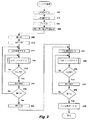
図2は、上述の例示的な実施形態を実現する処理を示すフローチャートである。この処理は、ノードがAPに登録された時又は再登録された時にトリガされてもよい。この処理はAPで実行されてもよく、処理のステップを実行するのに必要なソフトウェア及び/又はファームウェアは、例えば、フラッシュメモリであるAPの適切なコンピュータ可読媒体(不図示)に永続的に格納されてもよい。この処理は、ルーティングプロキシとして動作する能力を有するエンドポイントノードを含むネットワーク中の任意の他のノードにより実行されてもよい。処理の最初のいくつかのステップにおいて、種々の値が確立され、パラメータが初期化されてもよい。ステップ200において、時間間隔の合計数に対する値zが取得される。後続する各間隔が次のルーティング計測値と関連付けられてもよい上述の例において、zは許容される計測値の合計数、すなわち、15に等しい。ステップ202において、短い時間間隔の数nに対する値が取得される。この値は、6等のAPで格納される所定の数であってもよく、あるいは処理が実行される度に任意の所望の基準に基づいて計算されてもよい。
FIG. 2 is a flowchart illustrating a process that implements the exemplary embodiment described above. This process may be triggered when the node is registered or re-registered with the AP. This process may be performed at the AP, and the software and / or firmware needed to perform the steps of the process is permanently stored in an appropriate computer readable medium (not shown) of the AP, for example a flash memory. May be. This process may be performed by any other node in the network including endpoint nodes that have the ability to act as routing proxies. In the first few steps of the process, various values may be established and parameters may be initialized. In
ステップ204において、初期のより短い間隔の各々の長さT1が設定される。上述の例において、この継続時間は1分に設定されるが、例えば、ノードによる逐次的な登録の間の期間である可能性が高い相対的な伝播遅延であるネットワーク動作条件に基づく任意の適切な値であってもよい。ステップ206において、より長い間隔の各々の継続時間T2は上述の式を使用して計算される。
In
ステップ208において、ルーティング計測値は最初に0に設定され、ステップ210において、現在の間隔の長さINT、この場合は初期の間隔がT1に等しくなるように設定される。ステップ200〜210により処理の初期化が完了し、ルーティング計測値のアドバタイズを開始する準備が整う。
In
ステップ212において、タイマ、すなわち、カウンタCがゼロに再設定され、以降の時間のカウントを開始する。ステップ214において、APはノードまでのパスに対する現在のルーティング計測値Mをアドバタイズし、ステップ216において、タイマCがINTに対する値になったかをチェックする。従って、第1の間隔中、上述の例において1分が経過したか否かの判定が行なわれる。現在の間隔の継続時間全体がまだ経過していない場合、ステップ214に戻り、定期的にスケジュールされた時間にノードまでのパスに対するルーティング計測値をアドバタイズし続ける。例えば、上述したように、アドバタイズメントは、ステップ214のサブルーチン内で実行するルーティング更新タイマに基づいて30秒毎に同報通信されてもよい。
In
現在の間隔に対する時間が経過すると、ステップ216におけるチェックは肯定的な結果を生成し、ステップ218に進み、計測値Mは増分される。ステップ220において、Mに対する新しい値がnに等しいか否かの判定が行なわれる。換言すると、APへのノードの登録以降にn個の間隔が経過したかを確認するためのチェックが行なわれる。経過していない場合、ステップ212に戻り、APはルーティング計測値Mの新しい値を有するノードまでのパスをアドバタイズするために新しい間隔を開始する。ステップ212〜220は、n個のアドバタイズ間隔が経過するまで繰り返される。
When the time for the current interval has elapsed, the check in
n個の間隔が経過したことを示す肯定的な結果がステップ220で取得される場合、ステップ222に進む。このステップにおいて、間隔の継続時間INTは値T1からT2に変更される。その後、ステップ224〜232は、各間隔に対して増加したルーティング計測値を有するノードまでのパスをアドバタイズし続けるために実行される。しかし、この場合、間隔はより長い継続時間を有する。ルーティング計測値Mがzに等しいこと、すなわち、登録期間中の最後の間隔が完了したことがステップ232において判定されるまで、この処理は繰り返されて継続する。この時点において、ステップ234に進み、対応するノードまでのパスを無効にする。その後、処理は戻り、ノードによる新しい登録を待つ。
If a positive result is obtained at
表1及び図2の例において、階段関数は、ルーティング計測値の各増分値に対する間隔の長さを判定するために使用される。図3Aを参照すると、間隔の長さは、n個の間隔に対しては第1の所定の値T1に設定され、登録期間中の残りのz−n個の間隔に対しては第2の値T2に増加する。この例は所望の結果を達成するための唯一の可能な実現例ではないことが理解されるであろう。一般に、登録期間の開始と終了との間の間隔の継続時間の単調な増加をもたらす任意の関数がこの目的で使用されてもよい。例えば、間隔の長さを判定する関数において2つ以上のステップが採用されてもよい。例えば、最初のいくつかの間隔が短い継続時間を有し、第2のグループの間隔の各々が僅かに長い継続時間を有し、最後のグループの間隔が更に長い継続時間を有する。 In the example of Table 1 and FIG. 2, the step function is used to determine the length of the interval for each incremental value of the routing measurement. Referring to FIG. 3A, the length of the interval is set to a first predetermined value T1 for n intervals and second for the remaining z−n intervals during the registration period. Increase to value T2. It will be appreciated that this example is not the only possible implementation to achieve the desired result. In general, any function that results in a monotonic increase in the duration of the interval between the beginning and end of the registration period may be used for this purpose. For example, two or more steps may be employed in a function that determines the length of the interval. For example, the first few intervals have a short duration, each of the second group intervals has a slightly longer duration, and the last group interval has a longer duration.
別の実施形態において、間隔の長さは、登録期間に及ぶ一連の時間間隔にわたり漸進的に増加してもよい。例えば、後続する各間隔は、その先行する間隔よりある程度長くてもよい。本実施形態の一変形例において、図3Bに示すように間隔の長さは非線形的に増加してもよい。例えば、非線形性が放物線関数に対応する場合、現在の間隔の継続時間INTは、Mが0以外の場合にINT=aM2として計算される。式中、aは第1の間隔の継続時間であり、全ての間隔の合計が登録期間の長さと等しくなるように計算される。本実施形態の別の実現例において、後続する間隔の継続時間は、フィボナッチ数列に対応してもよい。更に別の実施形態において、計算された時間間隔は、2つのノード間のパスコストに基づいてもよい。更なる一実施形態において、時間間隔は、ノードによる別のルートへの切り替えの頻度に基づいてもよい。例えば、間隔の長さは、ネットワーク条件に基づいて単調に増加してもよい。 In another embodiment, the length of the interval may gradually increase over a series of time intervals that span the registration period. For example, each subsequent interval may be somewhat longer than its preceding interval. In a modification of the present embodiment, the interval length may increase nonlinearly as shown in FIG. 3B. For example, if the non-linearity corresponds to a parabolic function, the current interval duration INT is calculated as INT = aM 2 when M is non-zero. Where a is the duration of the first interval and is calculated so that the sum of all intervals is equal to the length of the registration period. In another implementation of this embodiment, the duration of subsequent intervals may correspond to a Fibonacci sequence. In yet another embodiment, the calculated time interval may be based on the path cost between two nodes. In a further embodiment, the time interval may be based on the frequency of switching to another route by the node. For example, the length of the interval may increase monotonically based on network conditions.
要約すると、RIP計測値は、登録期間全体にわたる相対的に長い更新間隔と関連する問題を最小限にしつつ、登録期間の開始時の相対的に短い更新間隔から利益を得るためにノードまでのパスのAPのアドバタイズメント中に変動する速度で増分されてもよい。他のノードは、2つ以上のノードが所望のノードまでのパスをアドバタイズする場合に所望のノードに接続する際に介する最適なAPを選択するために、これらのアドバタイズされた計測値を利用できる。アドバタイズメントの最小のRIP計測値を有するAPを選択することにより、所望のノードの最新の登録を有するAPが選択される可能性がより高い。 In summary, the RIP measurement is a path to a node to benefit from a relatively short update interval at the beginning of the registration period while minimizing the problems associated with relatively long update intervals throughout the registration period. It may be incremented at a varying rate during the advertisement of the AP. Other nodes can use these advertised measurements to select the best AP through which to connect to the desired node when two or more nodes advertise the path to the desired node. . By selecting the AP with the smallest RIP measurement of advertisement, it is more likely that the AP with the latest registration of the desired node will be selected.
同様に、2つ以上のノードが静的IPアドレスを有する所定のエンドポイントまでのパスを同時にアドバタイズしている場合、それらのノードはそのエンドポイントに対する最小のRIP計測値を含むアドバタイズメントを判定するために互いのアドバタイズメントを監視できる。最小のRIP計測値を有するノード以外の全てのノードは、自身のアドバタイズメントを終了し、それにより旧登録によるネットワークトラフィックを減少できる。従って、ユーティリティネットワークにおけるDA装置等の複数のAPを含むネットワークにおける静的IPアドレスを有する装置と関連する登録の曖昧さは回避される。 Similarly, if more than one node is advertising a path to a given endpoint with a static IP address at the same time, those nodes determine the advertisement containing the smallest RIP measurement for that endpoint. In order to monitor each other's advertisements. All nodes other than the node with the smallest RIP measurement value can finish their advertisement, thereby reducing network traffic due to old registration. Therefore, registration ambiguities associated with devices having static IP addresses in a network including multiple APs, such as DA devices in a utility network, are avoided.
上記説明は、当業者が本発明で説明したシステム及び方法を作成し且つ使用することを可能にするために提示され、特定の応用例及びその要求に関連して提供される。実施形態に対する種々の変形は、当業者には容易に明らかとなり、本発明で規定される一般的な原理は、請求の範囲の趣旨の範囲を逸脱せずに他の実施形態及び応用例に適用されてもよい。従って、示される実施形態に限定する意図はなく、本発明で開示される原理及び特徴と整合性のある最大範囲が与えられる。 The above description is presented to enable one of ordinary skill in the art to make and use the systems and methods described in the present invention and is provided in the context of a particular application and its needs. Various modifications to the embodiments will be readily apparent to those skilled in the art, and the general principles defined by the invention may be applied to other embodiments and applications without departing from the scope of the claims. May be. Accordingly, there is no intent to limit the illustrated embodiments to the maximum extent consistent with the principles and features disclosed in the present invention.
Claims (20)
第2のノードへの第1のノードの登録に対応する期間を、前記期間の開始時の時間間隔が前記期間の後半の時間間隔より短い継続時間を有するような一連の時間間隔に分割するステップと、
前記第1のノードと前記第2のノードとの間の通信パスに関連するコストであって、前記一連の時間間隔における後続の時間間隔に対して値が増加するコストを指定する計測値を前記時間間隔の各々に割り当てるステップと、
前記時間間隔の各々の間に、少なくとも1つのメッセージが同報通信される時間間隔と関連付けられる前記計測値を含む前記メッセージを前記第2のノードにより同報通信するステップと
を含むことを特徴とする方法。 A method of routing in a network,
Dividing the period corresponding to the registration of the first node with the second node into a series of time intervals such that the time interval at the start of the period has a shorter duration than the latter half of the period When,
A cost value associated with a communication path between the first node and the second node, the measurement value specifying a cost that increases with respect to a subsequent time interval in the series of time intervals; Assigning to each of the time intervals;
Broadcasting the message including the measurement value associated with a time interval during which at least one message is broadcast during each of the time intervals by the second node. how to.
前記一連の時間間隔の開始時のn個の第1の時間増分及び前記一連の時間間隔の終了時のx個の第2の時間間隔に分割され、
n+xは、前記一連の時間間隔における間隔の合計数zに等しく、
前記第1の時間間隔の各々は、所定の継続時間を有し、前記第2の時間増分の各々は、n個の第1の時間増分のうちの所定の時間間隔よりも長い継続時間を有する
ことを特徴とする請求項1記載の方法。 The period is
Divided into n first time increments at the start of the series of time intervals and x second time intervals at the end of the series of time intervals;
n + x is equal to the total number z of intervals in the series of time intervals;
Each of the first time intervals has a predetermined duration, and each of the second time increments has a duration that is longer than a predetermined time interval of the n first time increments. The method of claim 1 wherein:
ことを特徴とする請求項1記載の方法。 The method of claim 1, wherein the duration of the time interval increases sequentially over the series of time intervals.
ことを特徴とする請求項1記載の方法。 The method according to claim 1, wherein the message including the measurement value is a routing advertisement.
距離ベクトルルーティングプロトコルに準拠する
ことを特徴とする請求項4記載の方法。 The routing advertisement is
5. The method of claim 4, wherein the method is compliant with a distance vector routing protocol.
ことを特徴とする請求項1記載の方法。 The method according to claim 1, wherein the measured value is the number of hops.
ことを特徴とする請求項1記載の方法。 The method of claim 1, wherein the first node is associated with a device having a static IP address.
ことを特徴とする請求項7記載の方法。 The method of claim 7, wherein the network employs dynamic address assignment for registered nodes.
前記ノードは、登録される他のノードまでのパスを提供できるというアドバタイズメントを前記ネットワークを介して同報通信する送信ユニットを含み、
前記アドバタイズメントは、前記他のノードが登録されている期間にわたる一連の時間間隔中に送信されるメッセージを含み、
前記一連の時間間隔の初期の時間間隔は、前記一連の時間間隔の後半の時間間隔よりも短い継続時間を有し、
前記メッセージは、前記他のノードまでのパスと関連するコストを指定する計測値を含み、
前記指定されたコストの値は、前記一連の時間間隔の後続の時間間隔に対して増加する
ことを特徴とするノード。 A node in a communication network in which other nodes are registered to provide a communication path to a destination,
The node includes a transmission unit that broadcasts advertisements over the network that it can provide a path to other registered nodes;
The advertisement includes a message sent during a series of time intervals over the period in which the other node is registered,
An initial time interval of the series of time intervals has a shorter duration than a second half of the series of time intervals;
The message includes a measurement value that specifies a cost associated with a path to the other node;
The node characterized in that the specified cost value increases with respect to a subsequent time interval of the sequence of time intervals.
ことを特徴とする請求項9記載のノード。 The duration of the time interval conforms to a step function, each time interval in the first group of time intervals has a first duration, and a second group of time intervals in the second half of the series of time intervals. The node according to claim 9, wherein the time interval at has a duration longer than the first duration.
ことを特徴とする請求項9記載のノード。 The node of claim 9, wherein the duration of the time interval increases sequentially over the series of time intervals.
ことを特徴とする請求項11記載のノード。 The node according to claim 11, wherein the duration of the time interval increases nonlinearly.
ことを特徴とする請求項9記載のノード。 The node according to claim 9, wherein the measured value is the number of hops.
静的IPアドレスを有する装置と関連付けられる
ことを特徴とする請求項9記載のノード。 The other nodes are
The node according to claim 9, wherein the node is associated with a device having a static IP address.
登録されたノードに対して動的アドレス割り当てを採用する
ことを特徴とする請求項14記載のノード。 The network is
The node according to claim 14, wherein dynamic address assignment is adopted for the registered node.
前記一連の時間間隔の開始と終了との間で単調に増加する
ことを特徴とする請求項9記載のノード。 The duration of the time interval is
The node according to claim 9, wherein the node increases monotonically between the start and end of the series of time intervals.
前記第1のノードが登録される前記他のノードの各々において、前記他のノードが前記第1のノードまでのパスを提供できるというアドバタイズメントであり、前記第1のノードが登録されているある期間にわたる一連の時間間隔中に送信されるメッセージを含むアドバタイズメントを同報通信するステップであり、前記一連の時間間隔の初期の時間間隔が前記一連の時間間隔の後半の時間間隔よりも短い継続時間を有し、前記メッセージの各々が前記他のノードまでの前記パスと関連するコストを指定する計測値を含み、前記指定されたコストの値が前記一連の時間間隔における後続の時間間隔に対して増加する、ステップと、
別のノードが前記第1のノードまでのパスを提供できるというアドバタイズメントを前記他のノードの1つにおいて受信すると、前記受信したアドバタイズメントに含まれる前記計測値が前記第1のノードまでのパスに対して前記1つのノードにより同報通信される前記計測値よりも低いコストを指定しているか否かを判定するステップと、
前記受信したアドバタイズメントに含まれる前記計測値が前記1つのノードにより同報通信される前記計測値よりも低いコストを指定している場合、前記1つのノードからの前記アドバタイズメントの前記同報通信を終了するステップと
を含むことを特徴とする方法。 In a network in which a first node is registered with two or more other nodes that provide access rights to and access from the first node to provide a communication path to a destination A method,
In each of the other nodes to which the first node is registered, an advertisement that the other node can provide a path to the first node, and the first node is registered. Broadcasting an advertisement containing messages transmitted during a series of time intervals over a period of time, wherein an initial time interval of the series of time intervals is shorter than a later time interval of the series of time intervals Each of the messages includes a measurement value that specifies a cost associated with the path to the other node, wherein the specified cost value is relative to subsequent time intervals in the series of time intervals. Step by step,
When an advertisement that another node can provide a path to the first node is received at one of the other nodes, the measurement value included in the received advertisement is the path to the first node. Determining whether a cost lower than the measured value broadcasted by the one node is specified;
If the measurement value included in the received advertisement specifies a lower cost than the measurement value broadcast by the one node, the broadcast of the advertisement from the one node. And ending the method.
前記第1のノードが登録される前記他のノードの各々において、前記他のノードが前記第1のノードまでのパスを提供できるというアドバタイズメントであり、前記第1のノードが登録されているある期間にわたる一連の時間間隔中に送信されるメッセージを含むアドバタイズメントを同報通信するステップであり、前記一連の時間間隔の初期の時間間隔が前記一連の時間間隔の後半の時間間隔より短い継続時間を有し、前記メッセージの各々が前記他のノードまでの前記パスと関連するコストを指定する計測値を含み、前記指定されたコストの値が前記一連の時間間隔における後続の時間間隔に対して増加する、ステップと、
送信側ノードにおいて2つ以上の他のノードから前記アドバタイズメントを受信し、前記受信したアドバタイズメントに含まれる前記計測値それぞれに基づいて前記他のノードのうちの1つを選択するステップと、
前記他のノードのうちの前記選択された1つを介して前記送信側ノードから前記第1のノードにメッセージを送信するステップと
を含むことを特徴とする方法。 In a network in which a first node is registered with two or more other nodes that provide access rights to and access from the first node to provide a communication path to a destination A method,
In each of the other nodes to which the first node is registered, an advertisement that the other node can provide a path to the first node, and the first node is registered. Broadcasting an advertisement containing a message transmitted during a series of time intervals over a period of time, wherein an initial time interval of the series of time intervals is shorter than a later time interval of the series of time intervals Each of the messages includes a measurement value that specifies a cost associated with the path to the other node, and the specified cost value is relative to subsequent time intervals in the series of time intervals. Increasing, steps,
Receiving the advertisement from two or more other nodes at a transmitting node and selecting one of the other nodes based on each of the measurements included in the received advertisement;
Transmitting a message from the sending node to the first node via the selected one of the other nodes.
ことを特徴とする請求項17又は18記載の方法。 Before SL other nodes The method of claim 17 or 18, wherein it contains an access point in the network.
ことを特徴とする請求項17又は18記載の方法。 19. A method according to claim 17 or 18, wherein the first node has a static address and the network employs dynamic addressing to access nodes of the network.
Applications Claiming Priority (3)
| Application Number | Priority Date | Filing Date | Title |
|---|---|---|---|
| US12/335,420 | 2008-12-15 | ||
| US12/335,420 US8213357B2 (en) | 2008-12-15 | 2008-12-15 | Static addressing of devices in a dynamically routed network |
| PCT/US2009/006468 WO2010074713A1 (en) | 2008-12-15 | 2009-12-09 | Static addressing of devices in a dynamically routed network |
Publications (3)
| Publication Number | Publication Date |
|---|---|
| JP2012512559A JP2012512559A (en) | 2012-05-31 |
| JP2012512559A5 JP2012512559A5 (en) | 2013-05-23 |
| JP5442760B2 true JP5442760B2 (en) | 2014-03-12 |
Family
ID=41581170
Family Applications (1)
| Application Number | Title | Priority Date | Filing Date |
|---|---|---|---|
| JP2011540695A Active JP5442760B2 (en) | 2008-12-15 | 2009-12-09 | Static addressing of devices in dynamic routing networks |
Country Status (8)
| Country | Link |
|---|---|
| US (1) | US8213357B2 (en) |
| EP (1) | EP2218282B1 (en) |
| JP (1) | JP5442760B2 (en) |
| KR (1) | KR101603350B1 (en) |
| AR (1) | AR074675A1 (en) |
| AU (1) | AU2009324266B2 (en) |
| TW (1) | TW201043064A (en) |
| WO (1) | WO2010074713A1 (en) |
Families Citing this family (11)
| Publication number | Priority date | Publication date | Assignee | Title |
|---|---|---|---|---|
| US8213367B2 (en) | 2005-11-02 | 2012-07-03 | Texas Instruments Incorporated | Methods for dimensioning the control channel for transmission efficiency in communication systems |
| US8517112B2 (en) | 2009-04-30 | 2013-08-27 | Schlumberger Technology Corporation | System and method for subsea control and monitoring |
| CN102549880B (en) | 2009-05-07 | 2016-01-20 | 道明尼资源公司 | Utilize the voltage saving that senior meter contact facility and transformer station's lumped voltage control |
| US9582020B2 (en) | 2013-03-15 | 2017-02-28 | Dominion Resources, Inc. | Maximizing of energy delivery system compatibility with voltage optimization using AMI-based data control and analysis |
| US9553453B2 (en) | 2013-03-15 | 2017-01-24 | Dominion Resources, Inc. | Management of energy demand and energy efficiency savings from voltage optimization on electric power systems using AMI-based data analysis |
| US9678520B2 (en) | 2013-03-15 | 2017-06-13 | Dominion Resources, Inc. | Electric power system control with planning of energy demand and energy efficiency using AMI-based data analysis |
| US9847639B2 (en) | 2013-03-15 | 2017-12-19 | Dominion Energy, Inc. | Electric power system control with measurement of energy demand and energy efficiency |
| US9563218B2 (en) | 2013-03-15 | 2017-02-07 | Dominion Resources, Inc. | Electric power system control with measurement of energy demand and energy efficiency using t-distributions |
| US10732656B2 (en) | 2015-08-24 | 2020-08-04 | Dominion Energy, Inc. | Systems and methods for stabilizer control |
| CN110750332A (en) * | 2019-10-23 | 2020-02-04 | 广西梯度科技有限公司 | Method for setting static IP (Internet protocol) in Pod in Kubernetes |
| CN114696952B (en) * | 2022-02-21 | 2023-09-26 | 北京交通大学 | Network coding transmission method and system based on two-layer routing |
Family Cites Families (7)
| Publication number | Priority date | Publication date | Assignee | Title |
|---|---|---|---|---|
| US6097718A (en) * | 1996-01-02 | 2000-08-01 | Cisco Technology, Inc. | Snapshot routing with route aging |
| US5774876A (en) * | 1996-06-26 | 1998-06-30 | Par Government Systems Corporation | Managing assets with active electronic tags |
| JP4279046B2 (en) * | 2003-05-20 | 2009-06-17 | 古野電気株式会社 | Wireless terminal device having high-speed roaming processing means for wireless LAN |
| US8131647B2 (en) * | 2005-01-19 | 2012-03-06 | Amazon Technologies, Inc. | Method and system for providing annotations of a digital work |
| US8700800B2 (en) * | 2006-02-15 | 2014-04-15 | Tropos Networks, Inc. | Roaming of clients between gateways of clusters of a wireless mesh network |
| US8861367B2 (en) * | 2006-12-13 | 2014-10-14 | Tropos Networks, Inc. | Deletion of routes of routing tables of a wireless mesh network |
| US20080298382A1 (en) * | 2007-05-31 | 2008-12-04 | Matsushita Electric Industrial Co., Ltd. | Method, apparatus and system for progressive refinementof channel estimation to increase network data throughput and reliability |
-
2008
- 2008-12-15 US US12/335,420 patent/US8213357B2/en active Active
-
2009
- 2009-12-09 AU AU2009324266A patent/AU2009324266B2/en active Active
- 2009-12-09 EP EP09795580A patent/EP2218282B1/en active Active
- 2009-12-09 KR KR1020107014481A patent/KR101603350B1/en active IP Right Grant
- 2009-12-09 WO PCT/US2009/006468 patent/WO2010074713A1/en active Application Filing
- 2009-12-09 JP JP2011540695A patent/JP5442760B2/en active Active
- 2009-12-15 TW TW098142812A patent/TW201043064A/en unknown
- 2009-12-15 AR ARP090104890A patent/AR074675A1/en not_active Application Discontinuation
Also Published As
| Publication number | Publication date |
|---|---|
| JP2012512559A (en) | 2012-05-31 |
| AU2009324266B2 (en) | 2014-08-14 |
| AU2009324266A1 (en) | 2010-07-01 |
| EP2218282B1 (en) | 2012-05-30 |
| KR101603350B1 (en) | 2016-03-14 |
| US8213357B2 (en) | 2012-07-03 |
| KR20110106229A (en) | 2011-09-28 |
| TW201043064A (en) | 2010-12-01 |
| AR074675A1 (en) | 2011-02-02 |
| EP2218282A1 (en) | 2010-08-18 |
| US20100150059A1 (en) | 2010-06-17 |
| WO2010074713A1 (en) | 2010-07-01 |
Similar Documents
| Publication | Publication Date | Title |
|---|---|---|
| JP5442760B2 (en) | Static addressing of devices in dynamic routing networks | |
| JP5124638B2 (en) | Method and system for providing network and routing protocol for utility services | |
| US7996558B2 (en) | Methods and systems for a routing protocol | |
| JP4322206B2 (en) | Information self-transmission system and method in ad hoc peer-to-peer networks | |
| US7969889B2 (en) | Route and link evaluation in wireless mesh communications networks | |
| TWI384824B (en) | Method for providing routing protocols in a frequency hopping spread spectrum network | |
| CN102271050B (en) | Method and system for automatically configuring network equipment in Internet protocol version 6 (IPv6) network, and network equipment | |
| US20090003356A1 (en) | Node discovery and culling in wireless mesh communications networks | |
| US20090003243A1 (en) | Network utilities in wireless mesh communications networks | |
| US20090003214A1 (en) | Load management in wireless mesh communications networks | |
| US20140167979A1 (en) | Smart meter system, management router, and meter | |
| JP2017510190A (en) | Method for configuring node device, network, and node device | |
| US20150085696A1 (en) | Method for Discovering Neighboring Nodes in Wireless Networks | |
| Sampath et al. | " Ethernet on AIR': Scalable Routing in very Large Ethernet-Based Networks | |
| US9226219B2 (en) | System and method for route learning and auto-configuration | |
| CN109922442B (en) | Address resolution method for heterogeneous network of wireless multi-hop network and full-connection network | |
| Choi et al. | Random and linear address allocation for mobile ad hoc networks | |
| Choi et al. | Domain-based identifier-locator mapping management for distributed mobility control | |
| Pramod et al. | Characterization of wireless mesh network performance in an experimental test bed | |
| Bredy et al. | Rsvconf: Node autoconfiguration for manets | |
| US20230013924A1 (en) | Route discovery in networks with combo nodes | |
| Singh et al. | Optimization in route discovery delay for integrated manet with internet using extended aodv | |
| Bhatia et al. | A distributed prefix allocation scheme for subordinate manet | |
| Pagtzis et al. | Proactive mobility for future IP wireless access networks | |
| Lee et al. | Node configuration protocol based on hierarchical Network architecture for mobile Ad-Hoc networks |
Legal Events
| Date | Code | Title | Description |
|---|---|---|---|
| A521 | Request for written amendment filed |
Free format text: JAPANESE INTERMEDIATE CODE: A523 Effective date: 20100804 |
|
| A521 | Request for written amendment filed |
Free format text: JAPANESE INTERMEDIATE CODE: A523 Effective date: 20120323 |
|
| A621 | Written request for application examination |
Free format text: JAPANESE INTERMEDIATE CODE: A621 Effective date: 20120323 |
|
| A521 | Request for written amendment filed |
Free format text: JAPANESE INTERMEDIATE CODE: A523 Effective date: 20130520 |
|
| A131 | Notification of reasons for refusal |
Free format text: JAPANESE INTERMEDIATE CODE: A131 Effective date: 20130819 |
|
| A977 | Report on retrieval |
Free format text: JAPANESE INTERMEDIATE CODE: A971007 Effective date: 20130821 |
|
| A521 | Request for written amendment filed |
Free format text: JAPANESE INTERMEDIATE CODE: A523 Effective date: 20131106 |
|
| TRDD | Decision of grant or rejection written | ||
| A01 | Written decision to grant a patent or to grant a registration (utility model) |
Free format text: JAPANESE INTERMEDIATE CODE: A01 Effective date: 20131129 |
|
| A61 | First payment of annual fees (during grant procedure) |
Free format text: JAPANESE INTERMEDIATE CODE: A61 Effective date: 20131218 |
|
| R150 | Certificate of patent or registration of utility model |
Ref document number: 5442760 Country of ref document: JP Free format text: JAPANESE INTERMEDIATE CODE: R150 Free format text: JAPANESE INTERMEDIATE CODE: R150 |
|
| R250 | Receipt of annual fees |
Free format text: JAPANESE INTERMEDIATE CODE: R250 |
|
| R250 | Receipt of annual fees |
Free format text: JAPANESE INTERMEDIATE CODE: R250 |
|
| R250 | Receipt of annual fees |
Free format text: JAPANESE INTERMEDIATE CODE: R250 |
|
| S533 | Written request for registration of change of name |
Free format text: JAPANESE INTERMEDIATE CODE: R313533 |
|
| R350 | Written notification of registration of transfer |
Free format text: JAPANESE INTERMEDIATE CODE: R350 |
|
| R250 | Receipt of annual fees |
Free format text: JAPANESE INTERMEDIATE CODE: R250 |
|
| R250 | Receipt of annual fees |
Free format text: JAPANESE INTERMEDIATE CODE: R250 |
|
| R250 | Receipt of annual fees |
Free format text: JAPANESE INTERMEDIATE CODE: R250 |
|
| R250 | Receipt of annual fees |
Free format text: JAPANESE INTERMEDIATE CODE: R250 |
|
| R250 | Receipt of annual fees |
Free format text: JAPANESE INTERMEDIATE CODE: R250 |