JP5441121B2 - Automatic nondestructive inspection method and apparatus for tubular axles with varying inner and outer diameter shapes - Google Patents
Automatic nondestructive inspection method and apparatus for tubular axles with varying inner and outer diameter shapes Download PDFInfo
- Publication number
- JP5441121B2 JP5441121B2 JP2010512734A JP2010512734A JP5441121B2 JP 5441121 B2 JP5441121 B2 JP 5441121B2 JP 2010512734 A JP2010512734 A JP 2010512734A JP 2010512734 A JP2010512734 A JP 2010512734A JP 5441121 B2 JP5441121 B2 JP 5441121B2
- Authority
- JP
- Japan
- Prior art keywords
- probe
- wall
- axis
- map
- relative
- Prior art date
- Legal status (The legal status is an assumption and is not a legal conclusion. Google has not performed a legal analysis and makes no representation as to the accuracy of the status listed.)
- Active
Links
Images


Classifications
-
- G—PHYSICS
- G01—MEASURING; TESTING
- G01N—INVESTIGATING OR ANALYSING MATERIALS BY DETERMINING THEIR CHEMICAL OR PHYSICAL PROPERTIES
- G01N29/00—Investigating or analysing materials by the use of ultrasonic, sonic or infrasonic waves; Visualisation of the interior of objects by transmitting ultrasonic or sonic waves through the object
- G01N29/22—Details, e.g. general constructional or apparatus details
- G01N29/26—Arrangements for orientation or scanning by relative movement of the head and the sensor
- G01N29/262—Arrangements for orientation or scanning by relative movement of the head and the sensor by electronic orientation or focusing, e.g. with phased arrays
-
- G—PHYSICS
- G01—MEASURING; TESTING
- G01N—INVESTIGATING OR ANALYSING MATERIALS BY DETERMINING THEIR CHEMICAL OR PHYSICAL PROPERTIES
- G01N29/00—Investigating or analysing materials by the use of ultrasonic, sonic or infrasonic waves; Visualisation of the interior of objects by transmitting ultrasonic or sonic waves through the object
- G01N29/04—Analysing solids
- G01N29/06—Visualisation of the interior, e.g. acoustic microscopy
- G01N29/0609—Display arrangements, e.g. colour displays
-
- G—PHYSICS
- G01—MEASURING; TESTING
- G01N—INVESTIGATING OR ANALYSING MATERIALS BY DETERMINING THEIR CHEMICAL OR PHYSICAL PROPERTIES
- G01N29/00—Investigating or analysing materials by the use of ultrasonic, sonic or infrasonic waves; Visualisation of the interior of objects by transmitting ultrasonic or sonic waves through the object
- G01N29/22—Details, e.g. general constructional or apparatus details
- G01N29/225—Supports, positioning or alignment in moving situation
-
- G—PHYSICS
- G01—MEASURING; TESTING
- G01N—INVESTIGATING OR ANALYSING MATERIALS BY DETERMINING THEIR CHEMICAL OR PHYSICAL PROPERTIES
- G01N29/00—Investigating or analysing materials by the use of ultrasonic, sonic or infrasonic waves; Visualisation of the interior of objects by transmitting ultrasonic or sonic waves through the object
- G01N29/22—Details, e.g. general constructional or apparatus details
- G01N29/26—Arrangements for orientation or scanning by relative movement of the head and the sensor
- G01N29/265—Arrangements for orientation or scanning by relative movement of the head and the sensor by moving the sensor relative to a stationary material
-
- G—PHYSICS
- G01—MEASURING; TESTING
- G01N—INVESTIGATING OR ANALYSING MATERIALS BY DETERMINING THEIR CHEMICAL OR PHYSICAL PROPERTIES
- G01N29/00—Investigating or analysing materials by the use of ultrasonic, sonic or infrasonic waves; Visualisation of the interior of objects by transmitting ultrasonic or sonic waves through the object
- G01N29/22—Details, e.g. general constructional or apparatus details
- G01N29/26—Arrangements for orientation or scanning by relative movement of the head and the sensor
- G01N29/27—Arrangements for orientation or scanning by relative movement of the head and the sensor by moving the material relative to a stationary sensor
-
- G—PHYSICS
- G01—MEASURING; TESTING
- G01N—INVESTIGATING OR ANALYSING MATERIALS BY DETERMINING THEIR CHEMICAL OR PHYSICAL PROPERTIES
- G01N2291/00—Indexing codes associated with group G01N29/00
- G01N2291/10—Number of transducers
- G01N2291/106—Number of transducers one or more transducer arrays
-
- G—PHYSICS
- G01—MEASURING; TESTING
- G01N—INVESTIGATING OR ANALYSING MATERIALS BY DETERMINING THEIR CHEMICAL OR PHYSICAL PROPERTIES
- G01N2291/00—Indexing codes associated with group G01N29/00
- G01N2291/26—Scanned objects
- G01N2291/262—Linear objects
- G01N2291/2626—Wires, bars, rods
-
- G—PHYSICS
- G01—MEASURING; TESTING
- G01N—INVESTIGATING OR ANALYSING MATERIALS BY DETERMINING THEIR CHEMICAL OR PHYSICAL PROPERTIES
- G01N2291/00—Indexing codes associated with group G01N29/00
- G01N2291/26—Scanned objects
- G01N2291/263—Surfaces
- G01N2291/2634—Surfaces cylindrical from outside
-
- G—PHYSICS
- G01—MEASURING; TESTING
- G01N—INVESTIGATING OR ANALYSING MATERIALS BY DETERMINING THEIR CHEMICAL OR PHYSICAL PROPERTIES
- G01N2291/00—Indexing codes associated with group G01N29/00
- G01N2291/26—Scanned objects
- G01N2291/263—Surfaces
- G01N2291/2636—Surfaces cylindrical from inside
Description
本発明は、例えば、鉄道の分野に使用される車軸に関し、より具体的には、非破壊技術を使用してそのような軸を検査(または、点検)することに関する。 The present invention relates to axles used, for example, in the field of railways, and more particularly to inspecting (or inspecting) such axles using non-destructive techniques.
専門家が認識しているように、いくつかの車軸、特にかなりの量の負荷を支持しなければならないものは、国際標準に合致するために製造およびメンテナンスの異なる段階で、非破壊検査を経なければならない。公知の非破壊検査方法は、中実車軸に非常によく適合している。これらは、通常、超音波プローブを使用した音響分析に基づいており、場合によっては、例えば表面分析または放射線画像分析等の追加分析に基づいている。中実車軸が満たすべき標準は、特に、欧州では、NF EN13261−2004、世界的には、ISO5948−1994およびISO6933−1986、米国では、M 101/90−A(米国鉄道協会(Association of American Railroad)(AAR))、ブラジルでは、NBR7947−1989、日本では、JIS4502−1−2002である。 As experts recognize, some axles, especially those that must support a significant amount of load, undergo non-destructive testing at different stages of manufacturing and maintenance to meet international standards. There must be. Known non-destructive inspection methods are very well adapted to solid axles. These are usually based on acoustic analysis using an ultrasound probe, and in some cases based on additional analysis such as surface analysis or radiographic image analysis. The standards that solid axles must meet are NF EN13261-2004, especially in Europe, ISO 5948-1994 and ISO 6933-1986 worldwide, and M 101 / 90-A (Association of American Railroad in the United States). ) (AAR)), NBR 7947-1989 in Brazil, and JIS 4502-1-2002 in Japan.
取得された分析データから、軸を形成する中実材料内の横方向または長手方向の不完全部および欠陥の位置を推定し、これにより、この軸が国際標準(製造または定期メンテナンス)に合致するか否かを決定することが可能である。 From the acquired analytical data, the position of the lateral or longitudinal imperfections and defects in the solid material forming the axis is estimated, so that this axis meets international standards (manufacturing or routine maintenance) It is possible to determine whether or not.
いくつかの中実車軸を管状車軸と交換することが近年提案されたが、その壁は内外径形状が変化する。これらの新しい管状車軸は、通常は重量において30%程度の有意な減少を達成するため輸送される積荷の増加が可能となり、これに伴ってエネルギ消費が減少し、それゆえに汚染も減少するため、特に有利である。しかし、このタイプの管状車軸の検査は多数の問題を引き起こす。 Recently, it has been proposed to replace some solid axles with tubular axles, but the walls vary in inner and outer diameter shapes. These new tubular axles allow for an increased load to be transported to achieve a significant reduction in weight, typically on the order of 30%, which in turn reduces energy consumption and hence reduces pollution, Particularly advantageous. However, inspection of this type of tubular axle causes a number of problems.
当然、変化する内径形状が存在するため、角のある域(または隅)から生じるエコーを、不完全部または構造的欠陥から生じるエコーと区別することが困難である。 Of course, because of the changing inner diameter shape, it is difficult to distinguish echoes originating from cornered areas (or corners) from echoes originating from imperfections or structural defects.
さらに、かなりの数のこれらの不完全部および/または欠陥は、中実車軸で遭遇するものよりも小さな寸法を有し、超音波が移動する短い距離を考慮すると、検出がさらに困難になる。 In addition, a significant number of these imperfections and / or defects have smaller dimensions than those encountered on solid axles and are more difficult to detect given the short distance traveled by the ultrasound.
最後に、車軸を形成するために、特に車輪(圧力嵌め)およびブレーキディスク等のいくつかの器具を管状車軸のいくつかの部分に位置決めすることは、また、さらなる不完全部および/または構造的欠陥を招くのを免れないか、または、事前に行われた熱間鍛造および機械加工作業によって生じたいくつかの構造的欠陥および/または不完全部の寸法を増加させることさえある。結果として、最初の組み立て中および(器具を車軸から取り外すか取り外さないかにかかわらず)メンテナンス作業中の両方で、これらの部分および隣接する域を検査することがさらにより必要である。これらの分析を、車軸のいくつかの部分に器具が取り付けられているときに既存の検査方法で実行することは、困難であるか不可能でさえある。 Finally, in order to form the axle, positioning several instruments, in particular wheels (pressure fits) and brake discs, in some parts of the tubular axle also makes it possible to add further imperfections and / or structural It is inevitable to introduce defects, or even increases the size of some structural defects and / or imperfections caused by pre-formed hot forging and machining operations. As a result, it is even more necessary to inspect these parts and adjacent areas both during initial assembly and during maintenance operations (whether or not the instrument is removed from the axle). It is difficult or even impossible to perform these analyzes with existing inspection methods when instruments are attached to some parts of the axle.
本発明の目的は、したがって、管状車軸(より一般的には、中空(管状)回転製品)の大部分を、あるいは可能であればその全体を、器具が嵌められているときも含めて、少なくとも半自動の方法で、正確に検査する非破壊検査方法および装置を提案することである。 The object of the present invention is therefore at least a large part of the tubular axle (more generally a hollow (tubular) rotating product) or possibly the whole, including when the instrument is fitted. It is to propose a nondestructive inspection method and apparatus for accurately inspecting by a semi-automatic method.
この目的のために、下記のステップを備える管状車軸を検査する方法が提案される。すなわち、
a)既知の内外径形状が変化する壁を備える管状車軸を検査ベンチに置くステップと、
b)プローブに対して軸の様々な相対角位置用の分析データを取得するために、この壁の外側表面または内側表面の、その形状および軸の潜在的な負荷に応じて選択された第1のサイトに少なくとも1つの超音波プローブを置き、次いで、各プローブで、第1の長手方向または横方向に配向された第1の選択された角度セクタにおいて、壁の第1の選択された部分を分析するステップと、
c)プローブに対して軸の様々な相対角位置用の他の分析データを取得するために、これもまた形状および軸の潜在的な負荷に応じて選択された第2のサイトに、少なくとも1つのプローブを移動し、次いで、各移動されたプローブで、第1の方向とは反対の第2の方向に配向された第2の選択された角度セクタにおいて、壁の第2の選択された部分を分析するステップと、
d)取得された分析データから、壁内のエコーの表示の横方向または長手方向の配向および位置を表すマップを作成するステップとを有する方法である。
For this purpose, a method for inspecting a tubular axle comprising the following steps is proposed. That is,
a) placing a tubular axle with a wall of known inner and outer diameter shape on a test bench;
b) a first selected according to its shape and potential loading of the shaft on the outer or inner surface of this wall to obtain analytical data for various relative angular positions of the shaft relative to the probe. At least one ultrasound probe at each site and then with each probe a first selected portion of the wall in a first selected angular sector oriented in a first longitudinal or lateral direction. Analyzing, and
c) To obtain other analytical data for various relative angular positions of the shaft relative to the probe, this is also at least one at a second site selected according to shape and potential loading of the shaft. A second selected portion of the wall in a second selected angular sector that is moved in one probe and then oriented in a second direction opposite to the first direction with each moved probe Analyzing the steps,
d) creating from the acquired analysis data a map representing the lateral and longitudinal orientation and position of the display of echoes in the wall.
ここで、「エコーの表示」とは、(物質と空気の)接触面上または不完全部上または(構造的)欠陥上の反射によって、壁内に得られた情報を意味する。さらに、ここで、「不完全部」とは、エコーを発生させた壁の一部分であり、その振幅が選択された閾値よりも低く、したがって、結果として軸が不良品と判断される性質ではないものを意味する。最後に、ここでいう「欠陥」とは、エコーを発生させた壁の一部分であり、その振幅が選択された閾値よりも高く、したがって、結果として軸が不良品と判断される性質であるものを意味する。 Here, “echo display” means information obtained in a wall by reflection on a contact surface (substance and air) or on an imperfection or on a (structural) defect. Further, here, the “incomplete portion” is a part of the wall that caused the echo, and the amplitude thereof is lower than the selected threshold value, and thus the shaft is not judged to be defective as a result. Means things. Finally, the “defect” here is a part of the wall that caused the echo, whose amplitude is higher than the selected threshold, so that the axis is judged to be defective as a result. Means.
本発明によれば、本方法は、数種類の変形例に分けることができ、その少なくともいくつかの特徴は、互いに組み合わせることができ、特に、下記の通りである。 According to the invention, the method can be divided into several variants, at least some of which can be combined with one another, in particular as follows.
−例えば、壁内のエコーの表示の位置および配向を表すマップを作成するために、壁の外側表面に各超音波プローブを置くことによって、ステップb)〜d)を最初に実行することができる。その後、プローブに対する軸の様々な相対角位置用の分析データを取得し、ならびに、壁内のエコーの表示の位置および配向を表すマップを作成するために、形状に応じて選択される壁の内側表面の第3のサイトに少なくとも1つの超音波プローブを置くことによって、次いで、少なくとも1つの選択された長手方向または横方向に配向された第3の選択された角度セクタにおいて、各プローブで壁の第3の選択された部分を分析することによって、少なくともステップb)〜d)を二度目に実行することができる。 -Steps b) to d) can be performed first, for example by placing each ultrasound probe on the outer surface of the wall to create a map representing the position and orientation of the display of echoes in the wall. . Then, inside the wall selected according to the shape to obtain analytical data for various relative angular positions of the axis relative to the probe and to create a map representing the position and orientation of the display of echoes in the wall By placing at least one ultrasound probe at a third site of the surface, and then at each selected probe in the wall at each selected probe in at least one selected longitudinal or laterally oriented third selected angular sector. By analyzing the third selected portion, at least steps b) to d) can be performed a second time.
−例えば、長手方向に配向された角度セクタにおいて、超音波分析を実行し、これにより、壁内のエコーの表示の横方向の配向および位置を表すマップを作成するために、壁の外側表面または内側表面に各超音波プローブを置くことによって、ステップb)〜d)を少なくとも1回実行することができる。次いで、横方向に配向された角度セクタにおいて、超音波分析を実行し、これにより、壁内のエコーの表示の長手方向の配向および位置を表すマップを作成するために、壁の外側表面または内側表面に少なくとも1つの超音波プローブを置くことによって、ステップb)〜d)を再度少なくとも1回実行することができる。 -For example in longitudinally oriented angular sectors, to perform ultrasonic analysis, thereby creating a map representing the lateral orientation and position of the display of echoes in the wall or Steps b) to d) can be performed at least once by placing each ultrasound probe on the inner surface. Then, in a laterally oriented angular sector, an ultrasonic analysis is performed, thereby creating a map that represents the longitudinal orientation and position of the display of echoes in the wall, to the outside surface or inside of the wall By placing at least one ultrasound probe on the surface, steps b) to d) can be performed again at least once.
−ステップd)を実行した後に、例えばステップe)を提供することができ、その中で、軸に対する少なくとも1つのプローブの様々な相対角位置用の分析データを取得するために、超音波に基づいたものとは異なる他の分析技術を使用して、壁の少なくとも外側表面の分析が行われ、かつ、適用可能である場合には、これらの取得された分析データから、壁の表面表示の位置および配向を表すマップが作成されるステップf)を提供することができる。 After performing step d), for example, step e) can be provided, in which ultrasound is used to obtain analytical data for various relative angular positions of at least one probe relative to the axis If the analysis of at least the outer surface of the wall is performed using other analysis techniques different from those described above and is applicable, the position of the surface display of the wall is determined from these acquired analysis data. And a step f) in which a map representing the orientation is created can be provided.
例えば、この他の分析技術は、いわゆる漏洩磁束技術およびいわゆる渦電流技術から選択することができる。 For example, this other analysis technique can be selected from so-called leakage flux techniques and so-called eddy current techniques.
−壁の第1、第2、および該当する場合は第3の部分の各々は、例えば、軸に対する少なくとも1つのプローブの長手方向の相対変位によって、および/または、少なくとも1つのプローブで電子走査することによって、分析することができる。 Each of the first, second and, if applicable, third part of the wall is electronically scanned, for example, by a longitudinal relative displacement of the at least one probe relative to the axis and / or with at least one probe Can be analyzed.
−例えば、ステップb)、c)およびe)の少なくとも1つの実行中に、各プローブに対する軸の様々な相対角位置は、各プローブに対してこの軸を回転駆動することによって、または、この軸に対して各プローブを回転駆動することによって、のいずれかで得ることができる。 -For example, during the execution of at least one of steps b), c) and e), the various relative angular positions of the axis for each probe can be driven by rotating this axis relative to each probe or Can be obtained either by rotating each probe with respect to.
−この方法は、第1の参照マップに示されていないエコーの表示を表すデータのみを選択し、これにより、「訂正された」マップを作成するために、ステップd)中で得られたマップデータが、検査されたものと同一のタイプであるが欠陥のない第1の参照軸上で先に得られた第1の参照マップデータと比較されるステップg)を有してもよい。 -The method selects only the data representing the display of echoes not shown in the first reference map, and thereby the map obtained in step d) to create a "corrected" map The data may comprise a step g) in which the data is compared with the first reference map data obtained previously on a first reference axis which is of the same type as that which has been inspected but which is free of defects.
−この方法は、第2の参照マップに示された既知の欠陥を表すエコーの表示を表すデータのみを選択し、これにより、欠陥マップを作成するために、ステップd)またはg)中で得られたマップデータが、検査されたものと同一のタイプであるが既知の欠陥が含まれる第2の参照軸上で得られた第2の参照マップデータと比較されるステップh)を有してもよい。 The method selects only data representing echo representations of known defects shown in the second reference map, thereby obtaining in step d) or g) to create a defect map; Step h) wherein the obtained map data is compared with a second reference map data obtained on a second reference axis of the same type as that inspected but containing known defects Also good.
−この方法は、結果的に欠陥を示すものとなる、閾値振幅より高い振幅を備えたエコーの表示を表すデータのみを選択し、これにより、欠陥マップを作成するために、ステップd)またはg)中で得られたマップデータの振幅が、選択された閾値振幅と比較されるステップi)を有してもよい。 The method selects only data representing the display of echoes with an amplitude higher than the threshold amplitude, resulting in a defect, thereby creating a defect map in steps d) or g ) There may be a step i) in which the amplitude of the map data obtained in is compared with the selected threshold amplitude.
閾値振幅より高い振幅を検出する場合には、適用可能であれば、警告を発してもよい。 If an amplitude higher than the threshold amplitude is detected, a warning may be issued if applicable.
−この方法は、少なくとも1つのマップをスクリーンに表示するステップj)を有してもよい。 The method may comprise the step j) of displaying at least one map on the screen.
−例えば、単一の可変角度方向に超音波を放出することができるプローブが使用されてもよい。 -For example, a probe capable of emitting ultrasound in a single variable angular direction may be used.
例えば、角度は、長手方向または横方向に対して、約0度から約70度の間で変動してもよい。 For example, the angle may vary between about 0 degrees and about 70 degrees relative to the longitudinal or lateral direction.
−変形例として、例えば、選択された角度セクタにある方向に超音波を放出することができるいわゆるフェーズドアレイ型のプローブを使用することができる。 As a variant, it is possible to use, for example, a so-called phased array type probe that can emit ultrasonic waves in a direction in a selected angular sector.
例えば、角度セクタは、長手方向または横方向に対して、約0度から約70度の間であり得る。 For example, the angular sector can be between about 0 degrees and about 70 degrees relative to the longitudinal or transverse direction.
なお、ステップa)〜d)は、この順序で完了されなければならないが、他のステップe)〜j)は、必ずしもこの順序で完了する必要はない。特に、ステップj)をステップd)の後に実行することは十分に可能である。 Note that steps a) to d) must be completed in this order, but the other steps e) to j) are not necessarily completed in this order. In particular, it is sufficiently possible to carry out step j) after step d).
本発明はまた、車軸を検査するための装置にも関し、上述の方法を実施するように意図されている。この装置は、より具体的には下記を備える。すなわち、
−既知の内外径形状が変化する壁を備える管状車軸を受け取るように設計された検査ベンチと、
−選択された角度セクタにおいて、この壁の少なくとも1つの選択された部分を分析し、これにより、分析データを取得するように設計された少なくとも1つの超音波プローブと、
−第1および第2の対向する長手方向または横方向に配向された少なくとも1つの第1のおよび少なくとも1つの第2の選択された角度セクタにおいて、壁の少なくとも1つの第1のおよび少なくとも1つの第2の選択された部分をそれぞれ分析するように、ならびに、これにより、上記プローブに対する軸の様々な相対角位置用の分析データを取得するように、壁の外側表面または内側表面の、その形状および軸の潜在的な負荷に応じて選択される第1のサイトに各プローブを置くために、検査ベンチを制御するように設計された制御手段と、
−取得された分析データから、壁内のエコーの表示の長手方向または横方向の配向、および、長手方向または横方向の位置を表すマップを作成するように設計された処理手段とを備える装置である。
The invention also relates to a device for inspecting the axle, which is intended to implement the method described above. More specifically, this apparatus comprises: That is,
An inspection bench designed to receive a tubular axle with a wall of known inner and outer diameter shape change;
At least one ultrasonic probe designed to analyze at least one selected portion of the wall in a selected angular sector, thereby obtaining analytical data;
At least one first and at least one of the walls in at least one first and at least one second selected angular sector oriented in a first and second opposing longitudinal or transverse direction; The shape of the outer or inner surface of the wall so as to analyze each of the second selected portions and thereby obtain analytical data for various relative angular positions of the axis relative to the probe. And control means designed to control the examination bench to place each probe at a first site selected according to the potential load of the shaft;
An apparatus comprising a processing means designed to create a map representing the longitudinal or lateral orientation of the display of echoes in the wall and the longitudinal or lateral position from the acquired analytical data; is there.
本発明によれば、この装置は数種類の変形例に分けることができ、同装置の少なくともいくつかの特徴は、互いに組み合わせることができ、特に、下記の通りである。 According to the invention, this device can be divided into several variants, at least some features of which can be combined with one another, in particular as follows.
−その制御手段は、上記プローブに対する軸の様々な相対角位置用の分析データを取得するように、壁の外側表面に対する各プローブの相対変位を最初に制御する。次いで、選択された長手方向または横方向に配向された少なくとも1つの第3の選択された角度セクタにおいて、壁の少なくとも1つの第3の選択された部分を分析し、これにより、上記プローブに対する軸の様々な相対角位置用の他の分析データを取得するように、壁の内側表面に対する少なくとも1つのプローブの相対変位を二度目に制御するように設計することができる。この場合、処理手段は、取得された分析データから、壁内のエコーの表示の位置および配向を表すマップを作成するように設計される。 The control means first controls the relative displacement of each probe relative to the outer surface of the wall so as to obtain analytical data for various relative angular positions of the axis relative to the probe; Then, in at least one third selected angular sector oriented in a selected longitudinal or lateral direction, at least one third selected portion of the wall is analyzed, thereby providing an axis for the probe The relative displacement of the at least one probe relative to the inner surface of the wall can be designed to be controlled a second time to obtain other analytical data for various relative angular positions. In this case, the processing means is designed to create a map representing the position and orientation of the echo display in the wall from the acquired analysis data.
−この制御手段は、i)長手方向に配向された角度セクタにおいて、超音波分析を実行するように、それからエコーの表示の横方向の配向および位置を表すマップを処理手段が作成するもととなる分析データを取得するように、壁の外側表面または内側表面に対する各プローブの相対変位を少なくとも最初に制御し、次いで、ii)横方向に配向された角度セクタにおいて、超音波分析を実行し、それからエコーの表示の長手方向の配向および位置を表すマップを処理手段が作成するもととなる分析データを取得するように、壁の外側表面または内側表面に対する各プローブの相対変位を少なくとも二度目に制御するように設計されてもよい。 The control means i) the processing means creates a map representing the lateral orientation and position of the display of echoes, so as to perform an ultrasound analysis in the longitudinally oriented angular sector; At least initially control the relative displacement of each probe relative to the outer or inner surface of the wall so as to obtain analysis data comprising: ii) performing ultrasound analysis in a laterally oriented angular sector; The relative displacement of each probe relative to the outer or inner surface of the wall is then at least a second time so that the processing data can be obtained from which the processing means creates a map that represents the longitudinal orientation and position of the echo display. It may be designed to control.
−この装置は、プローブに対する軸の様々な相対角位置用の分析データを取得するために、超音波に基づいたものとは異なる他の分析技術を使用して、壁の少なくとも外側表面を分析するように設計された表面分析手段を備えてもよい。この場合、処理手段は、適用可能である場合には、(表面分析手段を通して取得された)これらの分析データから、壁の表面表示の位置および配向を表すマップを作成するように設計されてもよい。 -The device analyzes at least the outer surface of the wall using other analysis techniques different from those based on ultrasound to obtain analysis data for various relative angular positions of the axis relative to the probe Surface analysis means designed in such a way may be provided. In this case, the processing means may be designed to create a map representing the position and orientation of the wall surface representation from these analysis data (obtained through the surface analysis means), if applicable. Good.
例えば、表面分析手段は、漏洩磁束分析手段および渦電流分析手段から選択される。 For example, the surface analysis means is selected from leakage flux analysis means and eddy current analysis means.
−この装置は、軸に対して少なくとも1つのプローブを長手方向に相対的に変位させるように設計された変位手段を備えてもよい。この場合、その制御手段は、壁の第1、第2および可能であれば第3の部分の少なくとも一部を分析するように、軸に対して少なくとも1つのプローブを長手方向に相対的に変位させるように、変位手段を制御するように設計される。 The device may comprise displacement means designed to displace at least one probe relative to the axis in the longitudinal direction; In this case, the control means displaces at least one probe relative to the axis in the longitudinal direction so as to analyze at least part of the first, second and possibly third part of the wall. It is designed to control the displacement means.
−代替的にまたは追加的に、その制御手段は、壁の第1、第2および可能であれば第3の部分の少なくとも一部を分析するように、少なくとも1つのプローブで電子走査を実行するように設計ことができる。 -Alternatively or additionally, the control means performs an electronic scan with at least one probe so as to analyze at least part of the first, second and possibly third part of the wall. Can be designed as.
−そのベンチは、プローブに対して軸の様々な相対角位置を画成するために、各プローブに対して軸を回転駆動するように設計されてもよい。あるいは、ベンチは、上記プローブに対してこの軸の様々な相対角位置を画成するために、軸に対して少なくとも1つのプローブを回転駆動するように設計されてもよい。 The bench may be designed to rotationally drive the shaft relative to each probe to define various relative angular positions of the shaft relative to the probe. Alternatively, the bench may be designed to rotationally drive at least one probe relative to the axis to define various relative angular positions of this axis relative to the probe.
−その処理手段は、検査されるべき軸上で得られたマップデータを、検査されたものと同一のタイプであるが欠陥のない第1の参照軸上で得られた第1の参照マップデータと比較し、第1の参照マップに示されていないエコーの表示を表すデータのみを選択し、これにより、訂正されたマップを作成するように設計されてもよい。 The processing means converts the map data obtained on the axis to be inspected into first reference map data obtained on a first reference axis of the same type as the inspected but without defects; May be designed to select only data representing the display of echoes not shown in the first reference map, thereby creating a corrected map.
−その処理手段は、検査されるべき軸上で得られたマップデータを、検査されたものと同一のタイプであるが既知の欠陥が含まれる第2の参照軸上で得られた第2の参照マップデータと比較し、第2の参照マップに示された既知の欠陥を表すエコーの表示を表すデータのみを選択し、これにより、欠陥マップを作成するように設計されてもよい。 The processing means converts the map data obtained on the axis to be inspected into a second reference axis obtained on a second reference axis which is of the same type as that inspected but contains known defects; It may be designed to select only data representing the display of echoes representing the known defects shown in the second reference map compared to the reference map data, thereby creating a defect map.
−その処理手段は、検査されるべき軸上で得られたマップデータの振幅を、選択された閾値振幅と比較し、この閾値振幅より高い振幅を備えた、欠陥を示すエコーの表示を表すデータのみを選択し、これにより、欠陥マップを作成するように設計されてもよい。 The processing means compares the amplitude of the map data obtained on the axis to be inspected with a selected threshold amplitude, and represents data representing an indication of an echo indicating a defect with an amplitude higher than this threshold amplitude; May be designed to select only, thereby creating a defect map.
その処理手段は、閾値振幅より高い振幅を検出した場合に、警告を発するように設計してもよい。 The processing means may be designed to issue a warning when an amplitude higher than the threshold amplitude is detected.
−この装置は、その処理手段によって作成されたマップの少なくともいくつかを表示するのに適切なスクリーンを備えてもよい。 The device may comprise a screen suitable for displaying at least some of the maps created by the processing means.
−例えば、各プローブは、単一の可変角度方向に、例えば長手方向または横方向に対して、約0度から約70度の間に、超音波を放出するように設計されてもよい。 -For example, each probe may be designed to emit ultrasound in a single variable angular direction, for example between about 0 degrees and about 70 degrees relative to the longitudinal or transverse direction.
−あるいは、例えば、各プローブは、いわゆるフェーズドアレイ型であってもよく、選択された角度セクタにある方向に、例えば長手方向または横方向に対して、約0度から約70度の間に、超音波を放出するように設計されてもよい。 -Alternatively, for example, each probe may be of a so-called phased array type, in a direction in a selected angular sector, for example between about 0 and about 70 degrees relative to the longitudinal or transverse direction, It may be designed to emit ultrasound.
本発明の他の特徴および利点は、下記の詳細な説明および添付の図面から明らかになるであろう。 Other features and advantages of the present invention will become apparent from the following detailed description and the accompanying drawings.
添付の図面は、本発明を補足するだけではなく、適用可能である場合には、その定義の一部を成す目的でも使用することができる。 The accompanying drawings may be used not only to supplement the invention, but also to form part of its definition where applicable.
本発明の目的は、管状車軸の大部分を、可能であればその全体を、管状車軸に器具が嵌められているときも含めて、非破壊的にかつ少なくとも半自動的に検査するのを可能にすることである。 It is an object of the present invention to allow non-destructive and at least semi-automatic inspection of the majority of a tubular axle, if possible, including when the instrument is fitted on the tubular axle. It is to be.
検査されるべき管状軸は、品物または乗客を運ぶための貨車の車軸の一部を形成するように意図されていることが下記では想定されている。しかし、本発明はこの用途に限定されない。当然、これは、稼働中の応力、例えば疲労歪等を受け、それの壁が、既知の内外径形状が変化するいずれのタイプの中空(管状)回転製品に関する。 It is assumed in the following that the tubular shaft to be inspected is intended to form part of the axle of a wagon for carrying goods or passengers. However, the present invention is not limited to this application. Of course, this refers to any type of hollow (tubular) rotating product that is subjected to stresses during operation, such as fatigue strain, and whose walls change in known inner and outer diameter shapes.
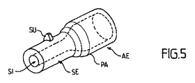
図1に示されるように、管状(車)軸AEは壁PAを有し、これは、熱間鍛造および機械加工作業によって画成され、最終的に可変の外半径R1および内半径R2の形状を呈する。なお、半径方向(すなわち、長手方向軸XXに垂直な方向)の厚さは、必ずしも一定ではない。換言すれば、外半径R1および内半径R2の形状は、必ずしも相似的に重なり合うことはできない。 As shown in FIG. 1, the tubular (wheel) axis AE has a wall PA, which is defined by hot forging and machining operations, and finally has a variable outer radius R1 and inner radius R2 shape. Presents. Note that the thickness in the radial direction (that is, the direction perpendicular to the longitudinal axis XX) is not necessarily constant. In other words, the shapes of the outer radius R1 and the inner radius R2 cannot necessarily overlap in a similar manner.
このタイプの軸の自動検査は、図1の形態のように器具を備えていないか、または、図2の形態のように器具EQ(例えば、特に、車輪および/またはブレーキディスク)を備えるかのいずれかの状態で、図3に概略的にかつ機能的に描かれたタイプの検査装置を使用して実行される。 Whether this type of automatic inspection of the shaft is not equipped with an instrument as in the form of FIG. 1 or with an instrument EQ (eg, in particular a wheel and / or a brake disc) as in the form of FIG. In either state, it is performed using an inspection device of the type schematically and functionally depicted in FIG.
そのような装置は、少なくとも1つの検査ベンチBCと、少なくとも1つの超音波プローブSU(ここでは、3つが示されている)と、制御モジュールMCと、処理モジュールMTと、好ましくはスクリーンECと、を有する。なお、制御モジュールMC、処理モジュールMTおよびスクリーンECは、図3の非限定的な例として示されるように、検査ベンチBCにおよび各プローブSUに接続されたマイクロコンピュータ(またはワークステーション)MOの一部を形成することができる。下記において、装置は少なくとも2つのプローブSUを有することが想定されている。 Such an apparatus comprises at least one examination bench BC, at least one ultrasound probe SU (here three are shown), a control module MC, a processing module MT, preferably a screen EC, Have Note that the control module MC, the processing module MT, and the screen EC are one of the microcomputers (or workstations) MO connected to the inspection bench BC and each probe SU, as shown as a non-limiting example in FIG. The part can be formed. In the following, it is assumed that the device has at least two probes SU.
検査ベンチBCは、例えば、支持部MSを備え、その上に、(器具の有無に係わらず)車軸AEと、制御モジュールMCによって生成された命令を受け取る際に選択された角部分にしたがって車軸AEを回転駆動するように設計された駆動軸ABと、を配置することができる。なお、選択された角部分は、完全回転に対応する360度に等しくてもよい。また、駆動軸ABが車軸AEも支持することができるときには、支持部MSを省略することができる。当然ながら、軸AEが回転駆動されるのを可能にする他のいずれの手段が考慮されてもよい。重要な事実は、ベンチBCが、プローブSUに対するこの軸AEの様々な相対角位置を規定するためにプローブSUに対して軸AEを回転駆動するか、または、プローブSUに対するこの軸AEの様々な相対角位置を規定するために軸AEに対してプローブSUを回転駆動するか、のいずれかを課されてもよいということである点に留意することが重要である。換言すれば、ベンチBCは、プローブSUに対する軸AEの相対的な位置決めを制御する。下記において、非限定的な例として、ベンチBCがプローブSUに対して軸AEを回転駆動することができることが容認される。 The inspection bench BC comprises, for example, a support MS, on which the axle AE (with or without the instrument) and the axle AE according to the corners selected when receiving the instructions generated by the control module MC. And a drive shaft AB designed to rotationally drive. Note that the selected corner portion may be equal to 360 degrees corresponding to full rotation. Further, when the drive shaft AB can also support the axle AE, the support portion MS can be omitted. Of course, any other means that allows the axis AE to be driven in rotation may be considered. The important fact is that the bench BC rotates the axis AE relative to the probe SU in order to define various relative angular positions of this axis AE relative to the probe SU, or the various of this axis AE relative to the probe SU. It is important to note that either the probe SU may be driven to rotate relative to the axis AE in order to define the relative angular position. In other words, the bench BC controls the relative positioning of the axis AE with respect to the probe SU. In the following, it will be accepted as a non-limiting example that the bench BC can rotationally drive the axis AE relative to the probe SU.
超音波プローブSUは、単一の方向に超音波を放出するような配列であり、その角度は選択されるが要件にしたがって変動可能な配列か、または、いわゆるフェーズドアレイ型であり、すなわち、要件にしたがって(角度電子走査によって)選択された角度セクタにある数方向に超音波を放出するような配列のいずれかの形で配列することができる。センサの長手方向変位の等価物もまた、電子走査を使用して得ることができる。 The ultrasonic probe SU is arranged so as to emit ultrasonic waves in a single direction, the angle of which is selected but can be varied according to the requirements, or is a so-called phased array type, that is, the requirements In accordance with (by angle electronic scanning) the array can be arranged in any form that emits ultrasound in several directions in the selected angular sector. An equivalent of the longitudinal displacement of the sensor can also be obtained using electronic scanning.
第1の場合(一方向性)では、各プローブSUは、分析されている壁PAから来るエコーを受信するように設計された単一の検出素子を有する。第2の場合(フェーズドアレイ・プローブ)では、各プローブSUは、様々な角度で(おそらく複数の)屈折および/または反射後に分析されている壁PAから来るエコーを受信するように設計された複数の検出素子を有する。検出素子は一般に複合材料から作られ、トランスデューサ上に置かれることが想起される。プローブの検出素子が励起されると、発散分析ビームを生成する。この形態およびそれに伴う入射の略方向は、プローブの検出素子の励起の選択された瞬間のレベルで時間遅延を導入することによって、電子的に修正することができる。プローブの検出素子と、所与の略方向で分析ビームを生成するために使用されるあらゆる関連した時間遅延との組み合わせは、通常、「仮想プローブ」と称される。フェーズドアレイ・プローブは、したがって、これが特徴とする組み合わせに応じて複数の(例えば、数ダースの)仮想プローブを形成することができる。トランスデューサの励起周波数は、通常、数メガヘルツ(2〜5MHz)程度ある。放出で励起されないときには、これらの同一の検出素子を使用して、物質と空気の接触面または物質と液体の接触面から来るエコー、不完全部および欠陥を検出する。それらは、これにより、エミッタ/レシーバタイプのセンサを形成する。 In the first case (unidirectional), each probe SU has a single detector element designed to receive the echo coming from the wall PA being analyzed. In the second case (phased array probe), each probe SU is designed to receive echoes coming from the wall PA being analyzed after refraction and / or reflection at different angles (possibly). The detecting element is provided. It is recalled that the sensing element is typically made from a composite material and placed on the transducer. When the detection element of the probe is excited, it generates a divergent analysis beam. This configuration and the resulting approximate direction of incidence can be corrected electronically by introducing a time delay at a selected instantaneous level of excitation of the probe's detector element. The combination of the probe's detector element and any associated time delay used to generate the analysis beam in a given approximate direction is commonly referred to as a “virtual probe”. A phased array probe can thus form multiple (eg, dozens) virtual probes depending on the combination that it features. The excitation frequency of the transducer is usually about several megahertz (2 to 5 MHz). When not excited by emission, these same sensing elements are used to detect echoes, imperfections and defects coming from the substance-air interface or the substance-liquid interface. They thereby form an emitter / receiver type sensor.
壁PAの内半径R2および外半径R1の形状、ならびに、軸AEの潜在的な負荷が、例えば、CIVA8.0タイプのシミュレーションソフトウェア(フランス原子力庁(CEA)により開発および販売されている)を使用して分析され、そのタイプ(一方向性またはフェーズドアレイ(および、この第2の場合には、検出素子の数))、ならびに、第1および第2の対向する方向にしたがって長手方向または横方向の分析を実行するように配向されることができるという事実に依存して、軸AEの全体または単に選択された部分のみを分析するために必要なプローブSUの数を決定するようにする。 The shape of the inner radius R2 and the outer radius R1 of the wall PA, and the potential load of the axis AE, for example, using simulation software of the CVA 8.0 type (developed and sold by the French Atomic Energy Agency (CEA)) Analyzed according to its type (unidirectional or phased array (and number of detector elements in this second case)) and longitudinal or transverse direction according to the first and second opposing directions. Depending on the fact that it can be oriented to perform an analysis of the above, it is determined to determine the number of probes SU needed to analyze the entire axis AE or just a selected portion.
ここで、「長手方向分析」とは、欠陥および/または不完全部を調べるために、好ましくは長手方向に配向され、または、長手方向XXに対して小鋭角(通常は±25度未満、好ましくは±5度未満の鋭角は)をなして実行される分析を意味する。「傾斜」という用語は、この欠陥配向を称するために使用されることもある。この分析は、長手方向XXに垂直な方向に放出されたビームを使用して実行され、すなわち、その略方向は、長手方向XXに垂直な平面に実質的に含まれるか、または、この垂直方向で小鋭角(通常は±10度未満)を作る。 Here, “longitudinal analysis” is preferably oriented in the longitudinal direction in order to examine defects and / or imperfections, or a small acute angle (usually less than ± 25 degrees, preferably in the longitudinal direction XX) Means an analysis performed with an acute angle of less than ± 5 degrees). The term “tilt” is sometimes used to refer to this defect orientation. This analysis is performed using a beam emitted in a direction perpendicular to the longitudinal direction XX, i.e. the approximate direction is substantially contained in a plane perpendicular to the longitudinal direction XX, or this perpendicular direction To make a small acute angle (usually less than ± 10 degrees).
さらに、「横方向分析」とは、欠陥および/または不完全部を調べるために、好ましくは横方向に配向され、または、長手方向XXに垂直な平面に対して小鋭角(典型的に±25度未満、好ましくは±5度未満の鋭角)を成して実行される分析を意味する。「傾斜」という用語は、この欠陥配向を称するために使用されることもある。この分析は、長手方向XXに平行な方向に放出されたビームを使用して実行され、すなわち、その略方向は、それ自体が長手方向XXを含む平面に実質的に含まれるか、または、この長手方向で小鋭角(通常は±10度未満)を作る。 Further, “lateral analysis” means a small acute angle (typically ± 25 relative to a plane that is preferably oriented laterally or perpendicular to the longitudinal direction XX to investigate defects and / or imperfections. Means an analysis carried out at an acute angle of less than degrees, preferably less than ± 5 degrees. The term “tilt” is sometimes used to refer to this defect orientation. This analysis is performed using a beam emitted in a direction parallel to the longitudinal direction XX, i.e. the approximate direction is substantially contained in a plane which itself comprises the longitudinal direction XX, or Make a small acute angle (usually less than ± 10 degrees) in the longitudinal direction.
軸AEの壁PAに通常見られる内半径R2および外半径R1の形状および軸AEの通常の負荷の形態を考慮して、一方向性プローブSUの放出の角度は、一般に、長手方向XXに対して、約0度から約70度の間で変動することができなければならず、フェーズドアレイ・プローブSUの放出の角度セクタは、一般に、長手方向XXに対して、約0度から約70度の間でなければならない。 Taking into account the shape of the inner radius R2 and the outer radius R1 normally found on the wall PA of the axis AE and the normal load configuration of the axis AE, the angle of discharge of the unidirectional probe SU is generally relative to the longitudinal direction XX. The angular sector of the emission of the phased array probe SU is generally about 0 to about 70 degrees relative to the longitudinal direction XX. Must be between.
第1の長手方向または横方向に配向された第1の選択された角度セクタにおいて、壁PAの第1の選択された部分を分析するように当初軸AEに対して置かれなければならない(第1の)選択されたサイト、および、第1の方向とは反対の第2の長手方向または横方向に配向された第2の選択された角度セクタにおいて、壁PAの第2の選択された部分を分析するようにその後軸AEに対して置かれなければならない可能な(第2の)選択されたサイトが各プローブSU用に決定されており、プローブSUは、第1のそれぞれの選択されたサイトに置かれることができる。 In the first selected angular sector oriented in the first longitudinal or transverse direction, it must be placed relative to the initial axis AE to analyze the first selected portion of the wall PA (first A second selected portion of the wall PA at a selected site and a second selected angular sector oriented in a second longitudinal or transverse direction opposite to the first direction. Possible (second) selected sites that must then be placed against the axis AE are determined for each probe SU, and the probe SU is the first respective selected Can be placed on the site.
軸AEに対するプローブSUのこの相対配置は、要件(および軸AEの構成)にしたがって、壁PAの外側表面SEまたはこの壁PAの内側表面SIのいずれかに位置する第1の選択されたサイトで実行することができる。まず、例えば、プローブSUを壁PAの外側表面SEに置くことによって超音波分析を行うことができ、次いで、適用可能である場合には、これらの分析は、その後、壁PAの内側表面SIに(すなわち、管状軸AEの内部に)プローブSUを置くことによって、これらの分析を補足することができる。しかし、逆もまた可能である。 This relative placement of the probe SU with respect to the axis AE depends on the requirements (and the configuration of the axis AE) at the first selected site located either on the outer surface SE of the wall PA or on the inner surface SI of this wall PA. Can be executed. First, for example, ultrasonic analysis can be performed by placing the probe SU on the outer surface SE of the wall PA and then, if applicable, these analyzes are then applied to the inner surface SI of the wall PA. These analyzes can be supplemented by placing the probe SU (ie within the tubular axis AE). However, the reverse is also possible.
プローブSUと壁PAの内側表面SIまたは外側表面SEとの間の接続は、当業者に公知のいずれの手段によっても達成することができ、特に、好ましくは防食剤と混合して、グリセリンを使用するかまたは水に浸漬することによって可能である。 The connection between the probe SU and the inner surface SI or the outer surface SE of the wall PA can be achieved by any means known to the person skilled in the art, in particular using glycerin, preferably mixed with an anticorrosive agent Or by soaking in water.
図4Aおよび4Bは、長手方向分析用に、軸AEの壁PAの一部の外側表面SEの2つの選択されたサイトにプローブSUを相対配置する2つの例を示す。図5はまた、横方向分析用に、軸AEの壁PAの一部の外側表面SEの選択されたサイトにプローブSUを相対配置する例を示す。図6はまた、長手方向分析用に、軸AEの壁PAの一部の内側表面SIの選択されたサイトにプローブSUを相対配置する例を示す。 4A and 4B show two examples of relative placement of a probe SU at two selected sites on the outer surface SE of a part of the wall PA of the axis AE for longitudinal analysis. FIG. 5 also shows an example of relative placement of the probe SU at selected sites on the outer surface SE of part of the wall PA of the axis AE for lateral analysis. FIG. 6 also shows an example of relative placement of the probe SU at selected sites on the inner surface SI of a part of the wall PA of the axis AE for longitudinal analysis.
プローブSUは、選択されたサイトの平面上に留まることによって、または、(当初選択されたサイトに対応する)開始位置と(他の選択されたサイトに対応する)終了位置との間で、1つまたはそれ以上の中間位置(各々が他の選択されたサイトに対応する位置)を経由して適用可能である場合には、相対的にかつ長手方向および/または横方向に変位されることによって、のいずれかで、それに割り当てられた部分を分析することができることに留意することが重要である。 The probe SU stays on the plane of the selected site, or between the start position (corresponding to the originally selected site) and the end position (corresponding to other selected sites) 1 By being displaced relatively and longitudinally and / or laterally, if applicable via one or more intermediate positions (each corresponding to another selected site) It is important to note that any of the parts assigned to it can be analyzed.
プローブSUのこれらの相対配置は、それに接続された変位手段MDを使用して実行することができる。各変位手段MDは、例えば、制御モジュールMCによって生成された命令にしたがって長手方向に変位することができるように、ベンチBCに対して並進で装着されたプローブキャリアである。なお、各プローブキャリアMDは、適用可能である場合には、第1の長手方向または横方向に配向された第1の選択された角度セクタにおける長手方向または横方向の分析(長手方向XXに対して垂直な放出の略方向)から、第1の方向とは反対の第2の長手方向または横方向に配向された第2の選択された角度セクタにおける長手方向または横方向の分析へ進むことができるように180度の角度で、または、第1および第2の選択された角度セクタにおける長手方向の分析から第3の選択された角度セクタにおける横方向の分析へ、ならびに、その逆に進むことができるように90度の角度で、のいずれかで、プローブSUの配向を変えるように回転駆動されてもよい。組み合わされた長手方向および横方向の変位から生じる分析もまた考えられる。 These relative arrangements of the probe SU can be performed using the displacement means MD connected to it. Each displacement means MD is, for example, a probe carrier that is mounted in translation with respect to the bench BC so that it can be displaced in the longitudinal direction according to instructions generated by the control module MC. Note that each probe carrier MD, if applicable, can be analyzed longitudinally or laterally in a first selected angular sector oriented in the first longitudinal or lateral direction (relative to the longitudinal direction XX). To the longitudinal or lateral analysis in a second selected angular sector oriented in a second longitudinal or transverse direction opposite to the first direction. Proceed as much as possible at an angle of 180 degrees or from longitudinal analysis in the first and second selected angular sectors to lateral analysis in the third selected angular sector and vice versa May be rotated to change the orientation of the probe SU, either at an angle of 90 degrees to allow. An analysis resulting from the combined longitudinal and lateral displacement is also conceivable.
プローブSUは固定されてもよく、一方、ベンチBCは、軸AEを長手方向に動かすことができ、かつ/あるいは、これを回転駆動することができる。軸AEに対してプローブSUを長手方向に動かしかつこれを回転駆動すること、または、逆も可能である。 The probe SU may be fixed, while the bench BC can move the axis AE in the longitudinal direction and / or drive it rotationally. It is also possible to move the probe SU longitudinally with respect to the axis AE and drive it rotationally, or vice versa.
1つの変形例において、制御モジュールMCは、壁PAの第1、第2および可能であれば第3の部分の少なくとも一部を分析するように、プローブSUの少なくともいくつかによる電子走査の実行を課されることがある。フェーズドアレイの選択されたサイトに位置するこれらの検出素子のいくつかを使用することによって、かつ、連続して放出するようにこれらの選択された検出素子に選択された遅延を割り当てることによって、プローブSU用の電子走査が得られることに留意すべきである。変位のこの「電子」的な方法は、プローブSUを機械的に動かす必要性を回避するので、有利である。 In one variant, the control module MC performs an electronic scan by at least some of the probes SU so as to analyze at least part of the first, second and possibly third part of the wall PA. May be imposed. Probes by using some of these detector elements located at selected sites of the phased array and assigning selected delays to these selected detector elements to emit continuously It should be noted that an electronic scan for SU is obtained. This “electronic” method of displacement is advantageous because it avoids the need to mechanically move the probe SU.
なお、少なくともいくつかのプローブSUがそれに割り当てられた壁の部分を分析できるようにするために、長手方向の(機械的)変位および電子走査の両方を組み合わせることも可能である。この場合、選択されたプローブSUを相対的にかつ長手方向に動かすように変位手段MDに対して必要な命令を生成し、電子走査を促すように選択されたプローブSUに必要な命令を生成することを課されてもよいのは、制御モジュールMCである。 It is also possible to combine both longitudinal (mechanical) displacement and electronic scanning so that at least some probes SU can analyze the part of the wall assigned to it. In this case, a command necessary for the displacement means MD is generated so as to move the selected probe SU relatively and longitudinally, and a command necessary for the selected probe SU is generated so as to prompt electronic scanning. It may be the control module MC that may be imposed.
また、選択された壁PAの全部分を分析するために使用される解法は、利用可能なプローブSUのタイプに依存し、さらに、フェーズドアレイ・プローブの場合には、それらを構成する検出素子の数に依存する。壁PAの割り当てられた部分を覆うような数のプローブSUの検出素子が適応される場合には、機械長手方向変位を提供する必要はないが、それは、電子走査で代用することができるからである。例えば、プローブSUが、100mmに等しい長手方向の延長により壁PAの一部を覆わなければならない場合には、例えば、一対の間が約0.1mmに等しい距離だけ離れた、0.5mmを測定する少なくとも200個の検出素子を備えなければならない。検出素子の寸法が小さくなればなるほど、分析の角度セクタは大きくなることが可能である点に留意すべきである。機械的な長手方向変位を回避するように、プローブSUの検出素子の数と電子走査によって提供される検査対象範囲を拡張する可能性との間に、妥協を見出すことができる。 Also, the solution used to analyze the entire portion of the selected wall PA depends on the type of probe SU available, and in the case of phased array probes, the detection elements that comprise them Depends on the number. If a number of probe SU sensing elements are applied to cover the assigned part of the wall PA, it is not necessary to provide a mechanical longitudinal displacement, since it can be substituted by electronic scanning. is there. For example, if the probe SU has to cover a part of the wall PA with a longitudinal extension equal to 100 mm, for example, measuring 0.5 mm with a distance between the pair being equal to about 0.1 mm There must be at least 200 detector elements. It should be noted that the smaller the size of the sensing element, the larger the angular sector of analysis can be. A compromise can be found between the number of sensing elements of the probe SU and the possibility of extending the examination area provided by electronic scanning so as to avoid mechanical longitudinal displacement.
フェーズドアレイ・プローブの使用は、一方向性プローブの使用よりも有利であるが、それは、超音波源のいずれの角変位を回避しながら、同一の角度セクタ分析でより良好な連続性を得ることができるからであることにも留意すべきである。 The use of a phased array probe is advantageous over the use of a unidirectional probe, but it obtains better continuity with the same angular sector analysis while avoiding any angular displacement of the ultrasound source It should also be noted that this is possible.
本発明によれば、ひとたびプローブSUが、第1のサイト(その形状および軸AEの潜在的な負荷に応じて選択される)で壁PAの外側表面SEまたは内側表面SIに置かれると、そのプローブSUの各々は、第1の長手方向または横方向に配向される第1の選択された角度セクタにおいて、壁PAの第1の割り当てられた部分の分析を開始する。各プローブSUは、これにより、上記プローブSUに対する軸AEの現在の相対角位置の分析データを取得することができる。連続した選択された角度セクタにおいて、軸AEを回転駆動することによって(ここでは、検査ベンチBCを使用して、例えば駆動軸ABで実施)、各プローブSUは、各角変位後に、分析データの新たな取得を実行することができる。分析データは、これにより、検査された壁PAの各第1の部分の全円周に関連して、得ることができる。 According to the present invention, once the probe SU is placed on the outer surface SE or inner surface SI of the wall PA at the first site (selected according to its shape and the potential load of the axis AE), Each of the probes SU initiates an analysis of the first assigned portion of the wall PA in a first selected angular sector oriented in a first longitudinal or lateral direction. Thereby, each probe SU can acquire analysis data of the current relative angular position of the axis AE with respect to the probe SU. By rotating and driving the axis AE in a series of selected angular sectors (here performed using the test bench BC, for example on the drive axis AB), each probe SU is subjected to analysis data after each angular displacement. A new acquisition can be performed. Analytical data can thereby be obtained in relation to the entire circumference of each first part of the examined wall PA.
例えば、これらの分析データは、放出角度、放出の瞬間および超音波の受信(または、これと同等である、放出の瞬間と受信の瞬間との間の時間間隔)、ならびに、受信角度を備える。例えば、選択された参照枠に対して第1の検査部分の長手方向位置および角位置に対応するメモリMYに格納することを課される制御モジュールMCへ、プローブSUによって、ならびに、適用可能である場合には、それらを得るために使用されるプローブSUの識別子によって、送信される。 For example, these analytical data comprise the emission angle, the instant of emission and the reception of ultrasound (or the equivalent time interval between the instant of emission and the instant of reception) and the reception angle. For example, applicable to the control module MC imposed to store in the memory MY corresponding to the longitudinal position and the angular position of the first examination part for the selected reference frame, as well as to the probe SU In some cases, transmitted by the identifier of the probe SU used to obtain them.
その後、プローブSUの少なくともいくつかが、(形状および軸AEの潜在的な負荷に応じて選択される)第2のサイトで壁PAの外側表面SEまたは内側表面SIに(相対的に)移動され、そのため、第1の方向とは反対の第2の長手方向または横方向に配向される第2の選択された角度セクタにおいて、それぞれ割り当てられた壁PAの第2の部分の分析を続行する。 Thereafter, at least some of the probes SU are moved (relatively) to the outer surface SE or inner surface SI of the wall PA at a second site (selected according to shape and potential load of the axis AE). Thus, the analysis of the second portion of each assigned wall PA is continued in a second selected angular sector oriented in a second longitudinal or transverse direction opposite to the first direction.
例えば、第1の方向が長手方向軸XXの左から右へ向かう方向に一致する場合には、第2の方向は、上記長手方向軸XXの右から左へ向かう方向に対応する。同様に、第1の方向が長手方向軸XXに垂直な第2の軸の左から右へ向かう方向に一致する場合には、第2の方向は、上記第2の軸の右から左へ向かう方向に一致する。 For example, when the first direction matches the direction from left to right of the longitudinal axis XX, the second direction corresponds to the direction from right to left of the longitudinal axis XX. Similarly, when the first direction matches the direction from the left to the right of the second axis perpendicular to the longitudinal axis XX, the second direction is from the right to the left of the second axis. Match the direction.
各移動されたプローブSUは、これにより、軸AEの現在の角位置の分析データを取得することができる。選択された角度セクタで軸AEを回転駆動することによって、各プローブSUは、各角変位後に、分析データの新たな取得を実行することができる。分析データは、これにより、検査された壁PAの各第2の部分の全円周に関連して、利用可能である。これらの分析データは、例えば、選択された参照枠に対して第2の検査部分の長手方向位置および角位置に対応してメモリに格納することを課される制御モジュールMCへ、プローブSUによって、ならびに、適用可能である場合には、それらを得るために使用されるプローブSUの識別子によって、送信される。 Each moved probe SU can thereby acquire analysis data of the current angular position of the axis AE. By rotating the axis AE in the selected angular sector, each probe SU can perform a new acquisition of analysis data after each angular displacement. Analytical data is thereby available in relation to the entire circumference of each second part of the examined wall PA. These analysis data are, for example, by the probe SU to the control module MC, which is required to store in memory corresponding to the longitudinal position and the angular position of the second inspection part with respect to the selected reference frame. And, if applicable, transmitted by the probe SU identifier used to obtain them.
対向する方向におけるこの二重分析の結果として、図7〜10に示されるように、車軸AEのすべてまたは一部を(要件にしたがって)検査することができる。より具体的には、下記の通りである。 As a result of this double analysis in opposing directions, all or part of the axle AE can be inspected (according to requirements) as shown in FIGS. More specifically, it is as follows.
−図7A〜7Cは、それぞれ、(右から左へ向かう)第1の長手方向に配向された30度、45度および60度に等しい放出角度用に、外側表面SEに置かれ相対的にかつ長手方向に右から左へ変位された3つの一方向性プローブによってカバーすることができる壁のパートの第1の部分を表す。 7A-7C are respectively placed on the outer surface SE relative to the first longitudinally oriented (from right to left) oriented emission angle equal to 30 degrees, 45 degrees and 60 degrees and 1 represents the first part of the part of the wall that can be covered by three unidirectional probes displaced longitudinally from right to left.
−図8A〜8Cは、それぞれ、(左から右へ向かう)第2の長手方向に配向された30度、45度および60度に等しい放出角度用に、外側表面SEに置かれ相対的にかつ長手方向に左から右へ変位された同一の3つの一方向性プローブによって検査することができる壁の同一のパートの第2の部分を表す。 8A-8C are respectively placed on the outer surface SE relative to the second longitudinally oriented (from left to right) oriented emission angle equal to 30 degrees, 45 degrees and 60 degrees and Fig. 4 represents a second part of the same part of the wall that can be examined by the same three unidirectional probes displaced longitudinally from left to right.
−図9Aは、(右から左へ向かう)第1の長手方向に配向された30度から70度の間の角度セクタ用に、外側表面SEに置かれた3つのフェーズドアレイ・プローブによって検査することができる壁の同一の一部の第1の部分を表す。 FIG. 9A inspects with three phased array probes placed on the outer surface SE for a first longitudinally oriented angular sector between 30 and 70 degrees (from right to left) Represents the first part of the same part of the wall.
−図9Bは、(左から右へ向かう)第2の長手方向に配向された30度から70度の間の角度セクタ用に、外側表面SEに置かれた同一の3つのフェーズドアレイ・プローブによって検査することができる壁の同一のパートの第2の部分を表す。 FIG. 9B shows the same three phased array probes placed on the outer surface SE for a second longitudinally oriented angle sector between 30 and 70 degrees (from left to right) Represents the second part of the same part of the wall that can be inspected.
−図10は、(左から右へ向かう)長手方向に配向された30度から70度の間の角度セクタ用に、内側表面SIに置かれた1つのフェーズドアレイ・プローブによって検査することができる壁の同一のパートの第3の部分を表す。 FIG. 10 can be inspected with one phased array probe placed on the inner surface SI for a longitudinally oriented angular sector between 30 and 70 degrees (from left to right) Represents the third part of the same part of the wall.
軸AEの壁PAに通常見られる内半径R2および外半径R1の形状および軸AEの通常の負荷の形態を鑑みて、一方向性プローブSUの放出の角度は、一般に、長手方向XXまたは横方向に対して、約0度から約70度の間で変動することができなければならず、フェーズドアレイ・プローブSUの放出の角度セクタは、一般に、長手方向XXまたは横方向に対して、約0度から約70度の間でなければならない。 In view of the shape of the inner radius R2 and the outer radius R1 normally found on the wall PA of the axis AE and the normal load configuration of the axis AE, the angle of discharge of the unidirectional probe SU is generally the longitudinal direction XX or the lateral direction. In contrast, it must be able to vary between about 0 degrees and about 70 degrees, and the angular sector of emission of the phased array probe SU is generally about 0, relative to the longitudinal direction XX or transverse direction. Must be between 70 degrees and about 70 degrees.
図7〜10の例において、各双方向矢印は、(上に置かれた)プローブSUによって分析される(第1の)部分の長手方向の延長を表す。車軸AEの負荷は、同一のプローブSUによって技術的に分析される(検査対象とされる)ことができる部分の長手方向延長を、いくつかの部分で、顕著に減少することが理解される。これは、車輪の下に位置する部分で特に見られ、この部分では圧力嵌めによっておよび/または支持される負荷によって生じた構造的欠陥を有する可能性が大きく、したがって、可能な限りもっとも注意深く完全な検査(分析)を経なければならない。 In the example of FIGS. 7-10, each double arrow represents a longitudinal extension of the (first) part analyzed by the probe SU (placed on it). It is understood that the load on the axle AE significantly reduces, in some parts, the longitudinal extension of the part that can be technically analyzed (subject to inspection) by the same probe SU. This is especially seen in the part located under the wheel, where it is likely to have structural defects caused by a press fit and / or by a supported load and is therefore the most carefully and completely possible It must go through inspection (analysis).
格納された分析データは、処理モジュールMTによって抽出され、次いで、横方向または長手方向の配向、および、壁PA内のエコーを示す位置を表すマップを作成するように関連する軸域に応じてグループ化が課される。 The stored analysis data is extracted by the processing module MT and then grouped according to the associated axial area to create a map representing the lateral or longitudinal orientation and the position representing the echo in the wall PA. Is imposed.
エコーの表示は、物質と空気の接触面もしくは物質と液体の接触面、または、不完全部、または、欠陥のいずれかにおける反射から生じることに留意すべきである。 It should be noted that the echo display results from reflections on either the substance-air contact surface or the substance-liquid contact surface, or an imperfection or defect.
長手方向分析は、(通常もっとも頻度が高い)横方向の不完全部および欠陥の検出に特に適しているが、一方、横方向分析は長手方向の不完全部および欠陥の検出に特に適していることにもまた留意すべきである。 Longitudinal analysis is particularly suitable for the detection of lateral imperfections and defects (usually the most frequent), while lateral analysis is particularly suitable for the detection of longitudinal imperfections and defects It should also be noted.
2つの対向する方向であるために非常に異なる分析の方向で物質を検査することは、より小さい寸法の不完全部および欠陥の検出を可能にし、したがって、中実軸に適応された先行技術によるこれまでの方法および検査装置で行うよりも多数の不完全部および欠陥を検出することを可能にする。しかし、同検査はまた、壁PA内部の斜めのかつ傾いた(または「傾斜した」)不完全部および欠陥の適切な検出を可能にする。 Inspecting materials in very different directions of analysis due to the two opposing directions allows for the detection of imperfections and defects of smaller dimensions and thus according to the prior art adapted to the solid axis This makes it possible to detect a greater number of imperfections and defects than is possible with previous methods and inspection devices. However, the inspection also allows for proper detection of diagonal and tilted (or “tilted”) imperfections and defects inside the wall PA.
なお、処理モジュールMTは、適用可能である場合には、壁の第1のおよび/または第2の部分検査対象区域を構成する同一域に関連する分析データの間で「相関」を示すように配列されてもよい。これにより、三次元タイプ(3D)が適用可能である場合には、対象範囲のこれらの区域の「未加工」マップを作成することができる。 It should be noted that the processing module MT, if applicable, shows a “correlation” between the analysis data relating to the same area constituting the first and / or second partial inspection area of the wall. It may be arranged. This makes it possible to create a “raw” map of these areas of the target range if the 3D type (3D) is applicable.
未加工マップを構成するデータファイルは、メモリMYに格納されることが好ましい。これらのマップは、次いで、スクリーンECに個別に(次々に)または一群で(一度に数個)表示され、技術者による分析を受けるか、または、最初に自動的に分析を受けるかのいずれかが可能であり、その後、「訂正された」マップまたは「欠陥」マップに変換されてスクリーンECに個別にまたは一群で表示されることが可能である。 The data files that make up the raw map are preferably stored in the memory MY. These maps are then displayed individually (one after the other) or in groups (a few at a time) on the screen EC and either analyzed by a technician or automatically analyzed first Can then be converted to a “corrected” map or a “defect” map and displayed individually or in groups on the screen EC.
数種類の対照分析は、「未加工」マップで実行することができる。 Several types of control analysis can be performed on “raw” maps.
例えば、処理モジュールMTには、検査されるべき軸AEで得られたマップのうち少なくともいくつかのマップのデータと、検査されたものと同一のタイプであるが欠陥のない第1の参照軸上で得られた第1の参照マップデータとの比較を課すことができる。この場合、処理モジュールMTは、メモリMYに格納する訂正されたマップを作成するために、第1の参照マップに示されていないエコーの表示を表すデータのみを選択する。 For example, the processing module MT may include data on at least some of the maps obtained on the axis AE to be inspected and on a first reference axis that is of the same type as the inspected but has no defects. A comparison with the first reference map data obtained in step 1 can be imposed. In this case, the processing module MT selects only data representing the display of echoes not shown in the first reference map in order to create a corrected map to be stored in the memory MY.
代替的にまたは追加的に、処理モジュールMTには、軸AEで得られた(未加工または訂正された)マップのうち少なくともいくつかのマップのデータと、検査されたものと同一のタイプであるが既知の欠陥が含まれる第2の参照軸上で得られた第2の参照マップからのデータとの比較を課すことができる。この場合、処理モジュールMTは、メモリMYに格納する欠陥マップを作成するために、第2の参照マップに示された既知の欠陥を表すエコーの表示を表すデータのみを選択する。 Alternatively or additionally, the processing module MT is of the same type as the data of at least some of the maps (raw or corrected) obtained with the axis AE and examined. Can impose a comparison with data from a second reference map obtained on a second reference axis that contains known defects. In this case, the processing module MT selects only data representing the display of echoes representing known defects shown in the second reference map in order to create a defect map to be stored in the memory MY.
代替的にまたは追加的に、処理モジュールMTには、少なくともいくつかのマップ上に表されたエコーの表示の振幅と、選択された閾値振幅との比較を課すことができる。この場合、処理モジュールMTは、欠陥マップを作成するために、選択された閾値振幅よりも高い、結果的に欠陥から生じると想定される振幅を備えたエコーの表示を表すデータのみを選択する。 Alternatively or additionally, the processing module MT may be imposed with a comparison of the amplitude of the echo representation represented on at least some maps with a selected threshold amplitude. In this case, the processing module MT selects only data representing an echo display with an amplitude that is assumed to result from the defect, which is higher than the selected threshold amplitude, in order to create a defect map.
さらに、処理モジュールMTは、選択された閾値振幅よりも高い振幅を検出するたびに、(聴覚および/または視覚(スクリーンEC上に表示される))警告を発することも可能である。 In addition, the processing module MT may issue a warning (audible and / or visual (displayed on the screen EC)) each time it detects an amplitude that is higher than the selected threshold amplitude.
車軸AEの同一の壁PAで得られる未加工マップの2つの例が、図11Aおよび11Bに示されている。検出された構造的な欠陥にはDSの符号が付されている。 Two examples of raw maps obtained on the same wall PA of the axle AE are shown in FIGS. 11A and 11B. Detected structural defects are labeled DS.
先に示されたように、壁PAは、プローブSUを外側表面SEにまたは内側表面SIに置くことによって、分析することができる。しかし、二重分析を行うこともでき、例えば、まずプローブSUを外側表面SEに置き、次いで、プローブSUのいくつかを内側表面SIに置く。より正確には、この場合、プローブSUに対する軸AEの様々な相対角位置用の分析データを取得するために、プローブSUは、壁PAの外側表面SEの、第1の選択されたサイトに置かれ、これらのプローブSUで、第1の長手方向(または横方向)に配向された第1の選択された角度セクタにおいて、壁PAの第1の選択された部分が分析される。次いで、プローブSUに対する軸AEの様々な相対角位置用の分析データを取得するために、プローブSUの少なくともいくつかが、壁PAの外側表面SEの、第2の選択されたサイトに移動され、これらのプローブSUで、第1の方向とは反対の第2の長手方向(または横方向)に配向された第2の選択された角度セクタにおいて、壁PAの第2の選択された部分が分析される。最後に、プローブSUに対する軸AEの様々な相対角位置用の分析データを取得するために、プローブSUの少なくともいくつかが、壁PAの内側表面SIの、第3の選択されたサイトに置かれ、これらのプローブSUで、少なくとも1つの長手方向(または横方向)に、または、場合によっては2つの対向する方向に、配向された第3の選択された角度セクタにおいて、壁PAの第3の選択された部分が分析される。 As indicated above, the wall PA can be analyzed by placing the probe SU on the outer surface SE or on the inner surface SI. However, a double analysis can also be performed, for example, first placing the probe SU on the outer surface SE and then placing some of the probes SU on the inner surface SI. More precisely, in this case, in order to obtain analytical data for various relative angular positions of the axis AE relative to the probe SU, the probe SU is placed at a first selected site on the outer surface SE of the wall PA. With these probes SU, a first selected portion of the wall PA is analyzed in a first selected angular sector oriented in a first longitudinal (or lateral) direction. Then, in order to obtain analytical data for various relative angular positions of the axis AE relative to the probe SU, at least some of the probes SU are moved to a second selected site on the outer surface SE of the wall PA, With these probes SU, a second selected portion of the wall PA is analyzed in a second selected angular sector oriented in a second longitudinal direction (or transverse direction) opposite to the first direction. Is done. Finally, in order to obtain analytical data for various relative angular positions of the axis AE relative to the probe SU, at least some of the probes SU are placed at a third selected site on the inner surface SI of the wall PA. , In these probes SU, in a third selected angular sector oriented in at least one longitudinal (or lateral) or possibly in two opposite directions, the third of the walls PA The selected part is analyzed.
次いで、処理モジュールMTは、すべての分析データから、壁PA内のエコーの表示の位置および配向を表すマップを作成する。 The processing module MT then creates a map representing the position and orientation of the echo display in the wall PA from all analysis data.
この外側と内側の二重分析は、検査されるべき壁PAの部分のすべてを対象とすることができるが、一方、この壁PAの形状および/または軸AEの負荷のため、外側分析のみによってすべての部分を対象とすることは、不可能であると判明する場合もある。 This outer and inner double analysis can cover all of the part of the wall PA to be examined, while due to the shape of this wall PA and / or the loading of the axis AE, only by the outer analysis It may prove impossible to cover all parts.
(上記に示されるように)両方向で外側に(または内側に)第1の長手方向分析を実行し、次いで、少なくとも一方向で外側に(または内側に)第2の横方向分析を実行するし、これにより壁PA内のエコーの表示の横方向の配向および位置を表すマップ、ならびに、同一の壁PA内のエコーの表示の長手方向の配向および位置を表すマップを作成することも可能である。 Performing a first longitudinal analysis outward (or inward) in both directions (as shown above) and then performing a second lateral analysis outward (or inward) in at least one direction It is also possible to create a map that represents the lateral orientation and position of the echo display within the wall PA, and a map that represents the longitudinal orientation and position of the echo display within the same wall PA. .
両方向で外側における第1の長手方向分析を実行し、次いで、少なくとも一方向で内側における第2の横方向分析を実行することも可能である。 It is also possible to perform a first longitudinal analysis on the outside in both directions and then a second lateral analysis on the inside in at least one direction.
両方向で内側に第1の横方向分析を実行し、次いで、少なくとも一方向で外側に第2の分析を実行することもまた可能である。 It is also possible to perform a first lateral analysis inward in both directions and then perform a second analysis outward in at least one direction.
原則として、内側および外側の長手方向および横方向の分析のすべての組み合わせが考えられる。 In principle, all combinations of inner and outer longitudinal and lateral analyzes are conceivable.
なお、場合によっては、内側分析は、この軸AEの内部に少なくとも1つのプローブSUを壁PAの内側表面SIに向けて置くのを可能にするように、適用可能である場合には適切な変位手段MDによる相対変位を可能にするように、管状車軸AEの少なくとも両端の口径を広げる必要があることもある。 It should be noted that in some cases, the inner analysis may be applied with an appropriate displacement, if applicable, so as to allow at least one probe SU to be placed inside this axis AE towards the inner surface SI of the wall PA. It may be necessary to widen the caliber at least at both ends of the tubular axle AE so as to allow relative displacement by means MD.
また、プローブSUを変位するためのサイト、プローブSUの各々の超音波による分析の様々な角度または様々な角度セクタ、および、様々なプローブに割り当てられた壁の部分は、適用可能である場合には、応力に応じて、選択が可能である。これにより、検査の一部はビームで行われ、その略方向は、長手方向XXをそれ自体が含む平面に実質的に含まれ、対で検査対象範囲の選択された率が例えば50%を呈する壁の部分にある場合で、および/または、検査の一部は連続ビームで行われ、その略方向は、この長手方向XXで0度から20度の間および0度から−20度の間である鋭角を形成する平面に実質的に含まれる場合が考えられる。さらに、プローブSUの検出素子の傾斜の角度は、要件にしたがって選択することができる。非限定的な例として、長手方向XXに対する45度の角度を選択することができる。 Also, the sites for displacing the probes SU, the various angles or the various angular sectors of the ultrasonic analysis of each of the probes SU, and the wall portions assigned to the various probes are applicable where applicable. Can be selected depending on the stress. Thereby, a part of the inspection is performed with a beam, the approximate direction of which is substantially included in a plane that itself includes the longitudinal direction XX, and the selected rate of the inspection object range in pairs exhibits, for example, 50%. When in the wall part and / or part of the examination is carried out with a continuous beam, the approximate direction being between 0 and 20 degrees and between 0 and -20 degrees in this longitudinal direction XX The case where it is substantially contained in the plane which forms a certain acute angle can be considered. Furthermore, the angle of inclination of the detection element of the probe SU can be selected according to the requirements. As a non-limiting example, an angle of 45 degrees with respect to the longitudinal direction XX can be selected.
当業者が認識しているように、各トランスデューサの増幅率は、例えば、壁PAの接触面から来る第1のエコーで得られた信号の振幅が、例えばマップ用に使用される総振幅動力の約50%に等しい振幅に相当するように、キャリブレーションフェーズ中に調整されなければならないことにもまた留意されたい。 As those skilled in the art are aware, the amplification factor of each transducer is, for example, the amplitude of the signal obtained with the first echo coming from the contact surface of the wall PA, for example the total amplitude power used for the map. Note also that it must be adjusted during the calibration phase to correspond to an amplitude equal to about 50%.
さらに、キャリブレーションフェーズはまた、好ましくは、検査されるべきものと同一のタイプであるが正常である(すなわち、不完全部および構造的欠陥がない)参照管状車軸上で実行される超音波分析の結果を表す、上記参照マップの取得専用の第1の部分も含む。当然、キャリブレーションフェーズのこの第1の部分は、壁PA(および特に隅、さらにより一般的には、内半径R2または外半径R1が著しく変動する区域)の形状配置によって発生するエコーを前もって知ることを可能にし、これにより、検査されるべき管状車軸AEの不完全部および構造的欠陥によって発生するものとの区別を可能にする。 In addition, the calibration phase is also preferably an ultrasonic analysis performed on a reference tubular axle that is the same type as that to be inspected but is normal (ie, free of imperfections and structural defects). The first part dedicated to the acquisition of the reference map representing the result of the above is also included. Of course, this first part of the calibration phase knows in advance the echoes generated by the geometry of the wall PA (and especially the corners, and even more generally the area where the inner radius R2 or the outer radius R1 varies significantly). This makes it possible to distinguish from those caused by imperfections and structural defects of the tubular axle AE to be inspected.
同様に、キャリブレーションフェーズはまた、検査されるべきものと同一のタイプの参照管状車軸上で実行される超音波分析の結果を表すが、この参照は、選択されたサイトで画成された特徴的な構造的または人工的な欠陥(例えば、特徴的なノッチまたはキャビティ等)を備える上記参照マップの取得専用の第2の部分も含むことができる。これらの特徴的な構造的または人工的な欠陥は、不完全部と欠陥とを分類するための閾値を定める仕様および/または標準にしたがって画成される。生来の欠陥上のエコーから来る信号の振幅が分類するための閾値よりも低い場合には、不完全部がある。これが閾値よりも高い場合には、欠陥がある。事実上、キャリブレーションフェーズのこの第2の部分は、特徴的な構造的または人工的な欠陥によって発生するエコーを前もって知ることを可能にし、これにより、検査されるべき管状車軸AEにおける類似タイプのエコー(または特徴)を発生させる「物体」を、分類するための閾値と比較することによって、マップ上でより容易に検出するのを可能にする。 Similarly, the calibration phase also represents the results of an ultrasound analysis performed on the same type of reference tubular axle as that to be examined, but this reference is a feature defined at the selected site. A second portion dedicated to obtaining the reference map with a typical structural or artificial defect (eg, a characteristic notch or cavity, etc.) may also be included. These characteristic structural or artificial defects are defined according to specifications and / or standards that define thresholds for classifying imperfections and defects. If the amplitude of the signal coming from the echo on the native defect is below the threshold for classification, there is an imperfection. If this is higher than the threshold, there is a defect. In effect, this second part of the calibration phase makes it possible to know in advance the echoes caused by characteristic structural or artificial defects, thereby allowing similar types of in the tubular axle AE to be inspected. The “object” that generates the echo (or feature) can be more easily detected on the map by comparing it to a threshold for classification.
ひとたび管状車軸AEの長手方向および/または横方向の超音波分析が完了すると、次いで、他のタイプの少なくとも1つの追加分析を実行することが可能になる。例えば、表面分析手段に対する軸AEの様々な相対位置用の表面分析データを取得するために、壁PAの外側表面SEの分析を実行することができる。 Once the longitudinal and / or transverse ultrasonic analysis of the tubular axle AE is complete, it is then possible to perform at least one additional analysis of another type. For example, an analysis of the outer surface SE of the wall PA can be performed to obtain surface analysis data for various relative positions of the axis AE relative to the surface analysis means.
使用することができる表面分析技術は、特に、いわゆる漏洩磁束技術およびいわゆる渦電流技術を含む。これらの技術のいくつかは有益であるが、それは、これらが、壁PAの表面欠陥の位置および配向を表すマップを作成することができる表面分析データを提供するからである。これらの表面欠陥マップのデータファイルは、技術者によって分析されるためにおよび/またはプローブSUで得られたマップと比較されるために、スクリーンECに、上記表面欠陥マップが個別に(次々と)または一群で(一度に数個)表示され、該当する場合には、(超音波によって得られる)構造的欠陥のマップも併せて表示されるように、メモリMYに格納されることが好ましい。こうすることで、表面欠陥マップおよび超音波によって得られたマップの装置による自動比較も可能となる。 Surface analysis techniques that can be used include in particular the so-called leakage flux technique and the so-called eddy current technique. Some of these techniques are beneficial because they provide surface analysis data that can create a map that represents the location and orientation of the surface defects on the wall PA. These surface defect map data files are individually (in turn) assigned to the screen EC for analysis by a technician and / or to be compared with the map obtained with the probe SU. Alternatively, it is preferably stored in the memory MY so that it is displayed in groups (several at a time) and, if applicable, a map of structural defects (obtained by ultrasound) is also displayed. By doing so, it is possible to automatically compare the surface defect map and the map obtained by the ultrasonic wave with the apparatus.
MPI(「磁粉探傷検査(Magnetic Particle Inspection)」)タイプの表面分析もまた実行することができることに留意されたい。この技術は、磁粉および蛍光剤を使用して壁PAの外側表面SEをカバーし、次いで、検査されるべき壁を磁化し、次いで、これらの磁粉の配向の不規則性、欠陥または不完全部の存在に連結した配向の不規則性を、UV(紫外線)灯下で視覚的な観察する(目で)ことを伴うことに留意すべきである。この表面分析技術の不利点は、現在、表面欠陥マップを提供せず、したがって、もっぱら軸AE上で検査を行う技術者による視覚的な観察に頼っており、その後、超音波によって得られたマップとの視覚的な非自動比較を必要とするという事実である。次いで、オペレータによる解釈および関連リスクに依存する。 It should be noted that MPI (“Magnetic Particle Inspection”) type surface analysis can also be performed. This technique uses magnetic powder and a fluorescent agent to cover the outer surface SE of the wall PA, then magnetizes the wall to be examined, and then irregularities, defects or imperfections in the orientation of these magnetic powders It should be noted that the orientational irregularities linked to the presence of are accompanied by visual observation (with eyes) under a UV (ultraviolet) lamp. The disadvantage of this surface analysis technique currently does not provide a surface defect map, and therefore relies exclusively on visual observation by an engineer inspecting on the axis AE, after which the map obtained by ultrasound The fact that it requires a visual non-automatic comparison with. It then depends on the interpretation by the operator and the associated risks.
上記に言及されたマップは、当業者には既知のいずれのタイプであってもよく、特に、A−スキャン、B−スキャン、C−スキャン、D−スキャンおよびS−スキャン(またはセクタスキャン)タイプであってもよいことにもまた留意されたい。純粋に例示的な目的のためにいうと、例えば、(一部の形状配置に関する不完全部の場所の描写を提供する)C−スキャンタイプのマップを作成することができ、該当する場合には、(固定プローブ位置で、容量における場所の表示を提供する)S−スキャンタイプのマップも可能である。 The maps mentioned above may be of any type known to those skilled in the art, in particular the A-scan, B-scan, C-scan, D-scan and S-scan (or sector scan) types. Note also that it may be. For purely exemplary purposes, for example, a C-scan type map (providing a description of the location of imperfections with respect to some geometry) can be created, if applicable , S-scan type maps are also possible (providing an indication of the location in the volume at a fixed probe position).
本発明のおかげで、厚さ約2mm(すなわち、壁PAの半径方向の公称厚さの約5%)、長さ約5mmおよび幅約1mmの不完全部および欠陥を検出することが可能である。さらに、通常は±25度よりも小さく、好ましくは±5度よりも小さい鋭角で傾斜を呈する長手方向および横方向の不完全部および欠陥を検出することができる。さらに、約60度までの失見当角度(または「傾斜角度」)を呈する長手方向または横方向のキャビティ(または「不備」)を検出することができる。 Thanks to the invention, it is possible to detect imperfections and defects with a thickness of about 2 mm (ie about 5% of the nominal radial thickness of the wall PA), a length of about 5 mm and a width of about 1 mm. . In addition, it is possible to detect longitudinal and lateral imperfections and defects that are inclined at an acute angle that is usually smaller than ± 25 degrees, preferably smaller than ± 5 degrees. Furthermore, longitudinal or lateral cavities (or “deficiencies”) exhibiting misregistration angles (or “tilt angles”) up to about 60 degrees can be detected.
本発明は、単に例として上述された管状車軸を検査するための方法および装置の例に限定されず、当業者によって下記特許請求の範囲の枠組み内にあるとみなされ得るすべての変形例を含む。 The present invention is not limited to the examples of methods and apparatus for inspecting a tubular axle described above by way of example only, but includes all variations that can be considered by those skilled in the art to be within the framework of the following claims. .
Claims (35)
a)既知の内外径形状が変化する壁(PA)を備える管状車軸(AE)を検査ベンチ(BC)に置くステップと、
b)前記壁(PA)の外側表面(SE)または内側表面(SI)の、その形状および前記軸(AE)の潜在的な負荷に応じて選択された第1のサイトに少なくとも1つの超音波プローブ(SU)を置き、次いで、各プローブ(SU)で、第1の長手方向または横方向に配向された第1の選択された角度セクタにおいて、前記壁(PA)の第1の選択された部分を分析し、前記プローブ(SU)に対して前記軸(AE)の様々な相対角位置用の分析データを取得するようにするステップと、
c)前記壁(PA)の形状および前記軸(AE)の前記潜在的な負荷に応じて選択された少なくとも1つの第2のサイトに、少なくとも1つのプローブ(SU)を移動し、次いで、各プローブ(SU)で、前記第1の方向とは反対の第2の方向に配向された第2の選択された角度セクタにおいて、前記壁(PA)の第2の選択された部分を分析し、前記プローブ(SU)に対して前記軸(AE)の様々な相対角位置用の他の分析データを取得するようにするステップと、
d)前記取得された分析データから、前記壁(PA)内のエコーの表示の横方向または長手方向の配向および位置を表すマップを作成するステップと、
を有し、
長手方向に配向された角度セクタにおいて、超音波分析を実行し、これにより、前記壁(PA)内のエコーの表示の横方向の配向および位置を表すマップを作成するように、前記壁(PA)の前記外側表面(SE)または前記内側表面(SI)に各超音波プローブ(SU)を置くことによって、ステップb)〜d)を少なくとも1回実行し、次いで、横方向に配向された角度セクタにおいて、超音波分析を実行し、これにより、前記壁(PA)内のエコーの表示の長手方向の配向および位置を表すマップを作成するように、前記壁(PA)の前記外側表面(SE)または前記内側表面(SI)に少なくとも1つの超音波プローブ(SU)を置くことによって、ステップb)〜d)を再度少なくとも1回実行することを特徴とする、方法。 A method for inspecting an axle using an ultrasonic probe,
a) placing a tubular axle (AE) with a wall (PA) of known inner and outer diameter shape on the inspection bench (BC);
b) At least one ultrasound at a first site selected according to its shape and potential load on the axis (AE) of the outer surface (SE) or inner surface (SI) of the wall (PA) Place a probe (SU) and then at each probe (SU) a first selected of the walls (PA) in a first selected angular sector oriented in a first longitudinal or lateral direction. Analyzing a portion to obtain analytical data for various relative angular positions of the axis (AE) relative to the probe (SU);
c) moving at least one probe (SU) to at least one second site selected according to the shape of the wall (PA) and the potential load of the axis (AE), then each Analyzing with a probe (SU) a second selected portion of the wall (PA) in a second selected angular sector oriented in a second direction opposite to the first direction; Obtaining other analytical data for various relative angular positions of the axis (AE) relative to the probe (SU);
d) creating from the acquired analysis data a map representing the lateral or longitudinal orientation and position of the display of echoes in the wall (PA) ;
Have
In the longitudinally oriented angular sector, ultrasound analysis is performed, thereby creating a map that represents the lateral orientation and position of the display of echoes in the wall (PA). Steps b) -d) are performed at least once by placing each ultrasonic probe (SU) on the outer surface (SE) or the inner surface (SI) of In the sector, an ultrasonic analysis is performed, thereby creating a map representing the longitudinal orientation and position of the display of echoes in the wall (PA), the outer surface (SE) of the wall (PA). ) Or at least one ultrasound probe (SU) on the inner surface (SI), and the steps b) to d) are performed again at least once .
を備え、
前記制御手段(MC)は、i)長手方向に配向された角度セクタにおいて、超音波分析を実行するように、ならびに、前記処理手段(MT)が作成するエコーの表示の横方向の配向および位置を表すマップから分析データを取得するように、前記壁(PA)の前記外側表面(SE)または前記内側表面(SI)に対する少なくとも1つのプローブ(SU)の相対変位を少なくとも最初に制御し、次いで、ii)横方向に配向された角度セクタにおいて、超音波分析を実行するように、ならびに、前記処理手段(MT)が作成するエコーの表示の長手方向の配向および位置を表すマップから分析データを取得するように、前記壁(PA)の前記外側表面(SE)または前記内側表面(SI)に対する少なくとも1つのプローブ(SU)の相対変位を少なくとも二度目に制御するように整えられることを特徴とする、装置。 An apparatus for inspecting an axle (AE), i) an inspection bench (BC) arranged to receive a tubular axle (AE) having a single wall (PA) of varying known inner and outer diameter shape; Ii) analyzing at least one selected portion of said wall (PA) in a selected angular sector, thereby at least one ultrasound probe (SU) arranged to obtain analytical data; Iii) first and second opposing longitudinal or transversely oriented at least one first and at least one second selected angular sector of at least one second of said wall (PA) 1 and at least one second selected portion, respectively, and accordingly, various phases of the axis (AE) relative to the probe (SU) A first selected according to its shape and potential loading of the axis of the outer surface (SE) or inner surface (SI) of the wall (PA) to obtain analytical data for angular position Control means (MC) arranged to control the examination bench (BC) to place each probe (SU) at the site, and iv) from the acquired analysis data, in the wall (PA) Processing means (MT) arranged to create a map representing the lateral and longitudinal orientation and position of the echo display ;
With
The control means (MC) i) perform ultrasonic analysis in longitudinally oriented angular sectors, and the lateral orientation and position of the display of echoes produced by the processing means (MT) At least initially control the relative displacement of at least one probe (SU) with respect to the outer surface (SE) or the inner surface (SI) of the wall (PA) so as to obtain analytical data from a map representing Ii) Analyzing data from a map representing the longitudinal orientation and position of the echo display produced by said processing means (MT) to perform ultrasonic analysis in a laterally oriented angular sector Relative variation of at least one probe (SU) relative to the outer surface (SE) or the inner surface (SI) of the wall (PA) to obtain Wherein the trimmed is possible to control at least a second time a device.
Applications Claiming Priority (3)
| Application Number | Priority Date | Filing Date | Title |
|---|---|---|---|
| FR0704435A FR2917832B1 (en) | 2007-06-21 | 2007-06-21 | METHOD AND APPARATUS FOR AUTOMATIC NON-DESTRUCTIVE CONTROL OF TUBULAR AXIS AXES WITH INTERNAL AND EXTERNAL VARIABLE RAY PROFILES |
| FR0704435 | 2007-06-21 | ||
| PCT/FR2008/000836 WO2009010653A2 (en) | 2007-06-21 | 2008-06-16 | Method and apparatus for the automatic non-destructive inspection of tubular axle pins having variable inside and outside radius profiles |
Publications (2)
| Publication Number | Publication Date |
|---|---|
| JP2010530528A JP2010530528A (en) | 2010-09-09 |
| JP5441121B2 true JP5441121B2 (en) | 2014-03-12 |
Family
ID=38895747
Family Applications (1)
| Application Number | Title | Priority Date | Filing Date |
|---|---|---|---|
| JP2010512734A Active JP5441121B2 (en) | 2007-06-21 | 2008-06-16 | Automatic nondestructive inspection method and apparatus for tubular axles with varying inner and outer diameter shapes |
Country Status (16)
| Country | Link |
|---|---|
| US (1) | US8336383B2 (en) |
| EP (1) | EP2158479B1 (en) |
| JP (1) | JP5441121B2 (en) |
| CN (1) | CN101765768B (en) |
| AR (1) | AR081473A1 (en) |
| AU (1) | AU2008277579B2 (en) |
| BR (1) | BRPI0812859B1 (en) |
| CA (1) | CA2691350C (en) |
| CL (1) | CL2008001853A1 (en) |
| EG (1) | EG26166A (en) |
| ES (1) | ES2472792T3 (en) |
| FR (1) | FR2917832B1 (en) |
| RU (1) | RU2453836C2 (en) |
| UA (1) | UA98964C2 (en) |
| WO (1) | WO2009010653A2 (en) |
| ZA (1) | ZA200908988B (en) |
Families Citing this family (18)
| Publication number | Priority date | Publication date | Assignee | Title |
|---|---|---|---|---|
| FR2917833B1 (en) * | 2007-06-21 | 2010-03-26 | V & M France | METHOD AND APPARATUS FOR MANUALLY NON-DESTRUCTIVE CONTROL OF TUBULAR AXIS AXES WITH INTERNAL AND EXTERNAL VARIABLE RAY PROFILES |
| US8453508B2 (en) | 2010-12-10 | 2013-06-04 | Ihi Southwest Technologies, Inc. | Testing of swing type check valves using phased array sequence scanning |
| US8839673B2 (en) * | 2012-05-02 | 2014-09-23 | Siemens Energy, Inc. | System and method for industrial ultrasonic inspection using phased array probe and distance-gain-size flaw sizing |
| US9027405B2 (en) * | 2012-11-20 | 2015-05-12 | General Electric Company | Ultrasonic inspection of an axle |
| DE102012112121B4 (en) * | 2012-12-11 | 2023-02-09 | Baker Hughes Digital Solutions Gmbh | Method and device for non-destructive testing of a rotationally symmetrical workpiece which has sections of different diameters |
| DE102012112120A1 (en) * | 2012-12-11 | 2014-06-26 | Ge Sensing & Inspection Technologies Gmbh | Method and device for near-surface non-destructive testing of a rotationally symmetrical workpiece with sections of varying diameter by means of ultrasound |
| CN103217477B (en) * | 2013-04-01 | 2015-02-11 | 清华大学 | Axle radial ultrasonic automatic flaw detecting device and control method |
| US9482645B2 (en) * | 2013-05-17 | 2016-11-01 | General Electric Company | Ultrasonic detection method and ultrasonic analysis method |
| JP6279863B2 (en) * | 2013-09-11 | 2018-02-14 | 東海旅客鉄道株式会社 | Ultrasonic flaw detector |
| CN105067704B (en) * | 2015-08-11 | 2018-02-06 | 北京新联铁集团股份有限公司 | Hole-bored axle from end to end fault detection system and method for detection |
| CN106312864A (en) * | 2015-11-18 | 2017-01-11 | 无锡市友佳车辆配件厂 | Magnetic type detecting device for vehicle frame |
| CN106324091A (en) * | 2015-11-18 | 2017-01-11 | 无锡市友佳车辆配件厂 | Novel car frame detection device |
| CN106312863A (en) * | 2015-11-18 | 2017-01-11 | 无锡市友佳车辆配件厂 | Suspension type detecting device for vehicle frame |
| CN106248788A (en) * | 2015-11-18 | 2016-12-21 | 无锡市友佳车辆配件厂 | The detection device of vehicle frame |
| KR102353788B1 (en) * | 2016-07-01 | 2022-01-19 | 일리노이즈 툴 워크스 인코포레이티드 | Integrated system and method for in situ 3-axis scanning and detection of defects in objects subjected to static and periodic testing |
| US10571432B2 (en) | 2016-08-31 | 2020-02-25 | General Electric Company | Methods, systems, and devices for solid axle testing |
| FR3068134B1 (en) * | 2017-06-23 | 2021-01-08 | Vallourec Tubes France | NON DESTRUCTIVE CONTROL FOR COMPLEX SHAPED TUBULAR PRODUCT |
| CN112858482B (en) * | 2021-01-14 | 2023-10-24 | 北京主导时代科技有限公司 | Ultrasonic automatic damage judging method and ultrasonic automatic damage judging system for hollow shaft |
Family Cites Families (28)
| Publication number | Priority date | Publication date | Assignee | Title |
|---|---|---|---|---|
| JPS5720660A (en) | 1980-07-11 | 1982-02-03 | Sumitomo Metal Ind Ltd | Apparatus and method of ultrasonic flaw detection |
| JPS5757346U (en) * | 1980-09-20 | 1982-04-03 | ||
| JPS5834358A (en) * | 1981-08-24 | 1983-02-28 | Kubota Ltd | Ultrasonic flaw detector for tube or the like |
| DE3604186A1 (en) * | 1986-02-10 | 1987-08-13 | Fraunhofer Ges Forschung | METHOD AND DEVICE FOR TESTING RAIL VEHICLE WHEELS UNDER OPERATING-LIKE LOAD CONDITIONS |
| DE3642717A1 (en) | 1986-12-13 | 1988-06-23 | Glyco Antriebstechnik Gmbh | METHOD FOR TESTING DRIVE AXLES AND DEVICE FOR CARRYING OUT THE METHOD |
| DE3728369A1 (en) * | 1987-08-21 | 1989-03-02 | Siemens Ag | METHOD FOR DETECTING CRACKS IN A SHAFT BY MEANS OF ULTRASONIC IMPULSE SECH METHOD AND DEVICE FOR IMPLEMENTING IT |
| DE3812824A1 (en) * | 1988-04-16 | 1989-11-02 | Asea Brown Boveri | TEST TEST FOR TESTING THE DRIVELINE OF A VEHICLE |
| DE3823764C2 (en) * | 1988-07-13 | 1993-11-25 | Fraunhofer Ges Forschung | Test rig for testing axle construction of a commercial vehicle |
| JPH0419558A (en) * | 1990-05-15 | 1992-01-23 | Tokyo Gas Co Ltd | Image processing method for ultrasonic flaw detection test |
| FR2678385B1 (en) * | 1991-06-28 | 1994-08-05 | Valdunes | METHOD AND DEVICE FOR ULTRASONIC CONTROL OF THE SURFACE CONDITION OF A BORE, ESPECIALLY THE BORE OF A RAILWAY AXLE. |
| US5426978A (en) * | 1992-10-09 | 1995-06-27 | Mitsubishi Denki Kabushiki Kaisha | Non-destructive axle flaw detecting apparatus |
| RU2084889C1 (en) * | 1993-08-10 | 1997-07-20 | Вячеслав Васильевич Лобанов | Method of ultrasonic test of articles having complex shape of bodies of revolution carrying pressed-on parts |
| RU2086975C1 (en) * | 1993-08-10 | 1997-08-10 | Лобанов Вячеслав Васильевич | Method of ultrasonic inspection of articles having complex form of bodies of revolution |
| CN2283856Y (en) * | 1996-12-18 | 1998-06-10 | 扬中市东大电子设备厂 | Computer supersonic detector for railway axle |
| JP2002082099A (en) * | 2000-09-07 | 2002-03-22 | Central Japan Railway Co | Ultrasonic flaw detector for hollow axle |
| JP2002257798A (en) * | 2001-02-28 | 2002-09-11 | Sumitomo Metal Ind Ltd | Flaw detection method and flaw detection device for solid shaft member |
| JP2003004710A (en) | 2001-06-21 | 2003-01-08 | Daido Steel Co Ltd | Method for inspecting padded pipe |
| BE1014836A6 (en) * | 2002-05-17 | 2004-05-04 | Vanhonacker Patrick | Test bench for measuring static and dynamic behavior of rail track comprises frame carrying low resonance frequency springs on which anti-vibration supports are fixed serving to carry track section on which carriage runs |
| US6945114B2 (en) * | 2002-11-25 | 2005-09-20 | The Johns Hopkins University | Laser-air, hybrid, ultrasonic testing of railroad tracks |
| CN1570620A (en) | 2003-07-23 | 2005-01-26 | Pii派普特罗尼克斯有限公司 | Method and equipment for detecting pipeline |
| US6886407B1 (en) | 2003-08-22 | 2005-05-03 | Westinghouse Electric Company Llc | Nondestructive examination of high pressure turbine cylinders |
| JP4351568B2 (en) * | 2004-03-30 | 2009-10-28 | 財団法人鉄道総合技術研究所 | Ultrasonic flaw detection method and apparatus |
| DE202004015456U1 (en) * | 2004-10-06 | 2005-10-13 | Cegelec Anlagen- Und Automatisierungstechnik Gmbh & Co. Kg | Ultrasonic non destructive internal bore test unit for rail vehicle axles has inspection head on telescopic mount driven by motorised compression stiff steel strips |
| US20060201253A1 (en) * | 2005-03-14 | 2006-09-14 | Transportation Technology Center, Inc. | System for non-contact interrogation of railroad axles using laser-based ultrasonic inspection |
| CN2842419Y (en) * | 2005-10-31 | 2006-11-29 | 中国南车集团戚墅堰机车车辆工艺研究所 | Built-in supersonic inspection combined probe for hollow car-axle |
| RU2313784C1 (en) * | 2006-05-10 | 2007-12-27 | Федеральное государственное унитарное предприятие "Научно-исследовательский институт мостов и дефектоскопии Федерального агентства железнодорожного транспорта" (НИИ мостов) | Mode of ultra sound control of the axles of wheel pairs |
| AT9467U3 (en) * | 2007-06-14 | 2008-07-15 | Avl List Gmbh | DEVICE AND METHOD FOR SIMULATING A DEVELOPMENT SYSTEM |
| FR2917833B1 (en) * | 2007-06-21 | 2010-03-26 | V & M France | METHOD AND APPARATUS FOR MANUALLY NON-DESTRUCTIVE CONTROL OF TUBULAR AXIS AXES WITH INTERNAL AND EXTERNAL VARIABLE RAY PROFILES |
-
2007
- 2007-06-21 FR FR0704435A patent/FR2917832B1/en not_active Expired - Fee Related
-
2008
- 2008-06-16 AU AU2008277579A patent/AU2008277579B2/en active Active
- 2008-06-16 CA CA2691350A patent/CA2691350C/en active Active
- 2008-06-16 EP EP08826362.9A patent/EP2158479B1/en active Active
- 2008-06-16 ES ES08826362.9T patent/ES2472792T3/en active Active
- 2008-06-16 BR BRPI0812859A patent/BRPI0812859B1/en active IP Right Grant
- 2008-06-16 RU RU2010101796/28A patent/RU2453836C2/en not_active IP Right Cessation
- 2008-06-16 CN CN200880100723.1A patent/CN101765768B/en active Active
- 2008-06-16 US US12/665,477 patent/US8336383B2/en active Active
- 2008-06-16 JP JP2010512734A patent/JP5441121B2/en active Active
- 2008-06-16 UA UAA201000544A patent/UA98964C2/en unknown
- 2008-06-16 WO PCT/FR2008/000836 patent/WO2009010653A2/en active Application Filing
- 2008-06-20 AR ARP080102643A patent/AR081473A1/en active IP Right Grant
- 2008-06-20 CL CL2008001853A patent/CL2008001853A1/en unknown
-
2009
- 2009-12-15 EG EG2009121829A patent/EG26166A/en active
- 2009-12-17 ZA ZA200908988A patent/ZA200908988B/en unknown
Also Published As
| Publication number | Publication date |
|---|---|
| WO2009010653A2 (en) | 2009-01-22 |
| EG26166A (en) | 2013-04-02 |
| EP2158479A2 (en) | 2010-03-03 |
| RU2010101796A (en) | 2011-07-27 |
| CN101765768B (en) | 2013-06-05 |
| CN101765768A (en) | 2010-06-30 |
| CA2691350C (en) | 2016-01-26 |
| EP2158479B1 (en) | 2014-03-26 |
| JP2010530528A (en) | 2010-09-09 |
| CL2008001853A1 (en) | 2008-12-26 |
| BRPI0812859A2 (en) | 2014-12-09 |
| UA98964C2 (en) | 2012-07-10 |
| BRPI0812859B1 (en) | 2019-01-02 |
| FR2917832B1 (en) | 2009-10-30 |
| AU2008277579B2 (en) | 2013-06-27 |
| AU2008277579A1 (en) | 2009-01-22 |
| US20100170344A1 (en) | 2010-07-08 |
| CA2691350A1 (en) | 2009-01-22 |
| RU2453836C2 (en) | 2012-06-20 |
| FR2917832A1 (en) | 2008-12-26 |
| ES2472792T3 (en) | 2014-07-03 |
| ZA200908988B (en) | 2010-09-29 |
| WO2009010653A3 (en) | 2009-03-19 |
| US8336383B2 (en) | 2012-12-25 |
| AR081473A1 (en) | 2012-09-19 |
Similar Documents
| Publication | Publication Date | Title |
|---|---|---|
| JP5441121B2 (en) | Automatic nondestructive inspection method and apparatus for tubular axles with varying inner and outer diameter shapes | |
| JP6441321B2 (en) | Improved inspection method by ultrasonic transmission | |
| JP5475654B2 (en) | Method and apparatus for manual nondestructive inspection of tubular axles with varying inner and outer diameter shapes | |
| JP4694576B2 (en) | Turbine component defect detection method and apparatus | |
| EP2669672B1 (en) | Apparatus and method for inspecting a tube | |
| EP2703806B1 (en) | Non-destructive evaluation methods for aerospace components | |
| JP5264896B2 (en) | Nondestructive detection method and apparatus for rotational movement of sample, and test unit | |
| KR20140137457A (en) | System and method for industrial ultrasonic inspection using phased array probe and distance-gain-size flaw sizing | |
| KR20130048795A (en) | Phased array ultrasonic inspection system for turbine and generator rotor bore | |
| JP6069123B2 (en) | Ultrasonic inspection apparatus and ultrasonic inspection method | |
| CN108431592A (en) | Equipment and its implementation for controlling and measuring the weld defect on cylindrical wall | |
| KR102044990B1 (en) | Ultrasonic testing method | |
| JP7180494B2 (en) | Ultrasonic flaw detector and ultrasonic flaw detection method |
Legal Events
| Date | Code | Title | Description |
|---|---|---|---|
| A621 | Written request for application examination |
Free format text: JAPANESE INTERMEDIATE CODE: A621 Effective date: 20110302 |
|
| A977 | Report on retrieval |
Free format text: JAPANESE INTERMEDIATE CODE: A971007 Effective date: 20120829 |
|
| A131 | Notification of reasons for refusal |
Free format text: JAPANESE INTERMEDIATE CODE: A131 Effective date: 20130423 |
|
| A601 | Written request for extension of time |
Free format text: JAPANESE INTERMEDIATE CODE: A601 Effective date: 20130716 |
|
| A602 | Written permission of extension of time |
Free format text: JAPANESE INTERMEDIATE CODE: A602 Effective date: 20130723 |
|
| A601 | Written request for extension of time |
Free format text: JAPANESE INTERMEDIATE CODE: A601 Effective date: 20130918 |
|
| A602 | Written permission of extension of time |
Free format text: JAPANESE INTERMEDIATE CODE: A602 Effective date: 20130926 |
|
| A521 | Request for written amendment filed |
Free format text: JAPANESE INTERMEDIATE CODE: A523 Effective date: 20131021 |
|
| TRDD | Decision of grant or rejection written | ||
| A01 | Written decision to grant a patent or to grant a registration (utility model) |
Free format text: JAPANESE INTERMEDIATE CODE: A01 Effective date: 20131112 |
|
| A61 | First payment of annual fees (during grant procedure) |
Free format text: JAPANESE INTERMEDIATE CODE: A61 Effective date: 20131211 |
|
| R150 | Certificate of patent or registration of utility model |
Ref document number: 5441121 Country of ref document: JP Free format text: JAPANESE INTERMEDIATE CODE: R150 Free format text: JAPANESE INTERMEDIATE CODE: R150 |
|
| R250 | Receipt of annual fees |
Free format text: JAPANESE INTERMEDIATE CODE: R250 |
|
| R250 | Receipt of annual fees |
Free format text: JAPANESE INTERMEDIATE CODE: R250 |
|
| R250 | Receipt of annual fees |
Free format text: JAPANESE INTERMEDIATE CODE: R250 |
|
| R250 | Receipt of annual fees |
Free format text: JAPANESE INTERMEDIATE CODE: R250 |
|
| R250 | Receipt of annual fees |
Free format text: JAPANESE INTERMEDIATE CODE: R250 |
|
| R250 | Receipt of annual fees |
Free format text: JAPANESE INTERMEDIATE CODE: R250 |
|
| R250 | Receipt of annual fees |
Free format text: JAPANESE INTERMEDIATE CODE: R250 |