JP5438101B2 - High bulk acoustic resonator type resonator with high temperature stability - Google Patents
High bulk acoustic resonator type resonator with high temperature stability Download PDFInfo
- Publication number
- JP5438101B2 JP5438101B2 JP2011512180A JP2011512180A JP5438101B2 JP 5438101 B2 JP5438101 B2 JP 5438101B2 JP 2011512180 A JP2011512180 A JP 2011512180A JP 2011512180 A JP2011512180 A JP 2011512180A JP 5438101 B2 JP5438101 B2 JP 5438101B2
- Authority
- JP
- Japan
- Prior art keywords
- resonator
- piezoelectric transducer
- acoustic
- equal
- frequency
- Prior art date
- Legal status (The legal status is an assumption and is not a legal conclusion. Google has not performed a legal analysis and makes no representation as to the accuracy of the status listed.)
- Expired - Fee Related
Links
- 238000005520 cutting process Methods 0.000 claims description 77
- 239000000758 substrate Substances 0.000 claims description 74
- 239000010453 quartz Substances 0.000 claims description 52
- VYPSYNLAJGMNEJ-UHFFFAOYSA-N silicon dioxide Inorganic materials O=[Si]=O VYPSYNLAJGMNEJ-UHFFFAOYSA-N 0.000 claims description 52
- 239000000463 material Substances 0.000 claims description 48
- 230000010287 polarization Effects 0.000 claims description 37
- 230000008878 coupling Effects 0.000 claims description 30
- 238000010168 coupling process Methods 0.000 claims description 30
- 238000005859 coupling reaction Methods 0.000 claims description 30
- GQYHUHYESMUTHG-UHFFFAOYSA-N lithium niobate Chemical compound [Li+].[O-][Nb](=O)=O GQYHUHYESMUTHG-UHFFFAOYSA-N 0.000 claims description 20
- WSMQKESQZFQMFW-UHFFFAOYSA-N 5-methyl-pyrazole-3-carboxylic acid Chemical compound CC1=CC(C(O)=O)=NN1 WSMQKESQZFQMFW-UHFFFAOYSA-N 0.000 claims description 9
- 229910013641 LiNbO 3 Inorganic materials 0.000 claims description 8
- 238000004519 manufacturing process Methods 0.000 claims description 7
- PCHJSUWPFVWCPO-UHFFFAOYSA-N gold Chemical compound [Au] PCHJSUWPFVWCPO-UHFFFAOYSA-N 0.000 claims description 6
- 229910052737 gold Inorganic materials 0.000 claims description 6
- 239000010931 gold Substances 0.000 claims description 6
- UKDIAJWKFXFVFG-UHFFFAOYSA-N potassium;oxido(dioxo)niobium Chemical compound [K+].[O-][Nb](=O)=O UKDIAJWKFXFVFG-UHFFFAOYSA-N 0.000 claims description 6
- 229910052751 metal Inorganic materials 0.000 claims description 5
- 239000002184 metal Substances 0.000 claims description 5
- -1 ammonium nitride Chemical class 0.000 claims description 4
- RYGMFSIKBFXOCR-UHFFFAOYSA-N Copper Chemical compound [Cu] RYGMFSIKBFXOCR-UHFFFAOYSA-N 0.000 claims description 3
- XLOMVQKBTHCTTD-UHFFFAOYSA-N Zinc monoxide Chemical compound [Zn]=O XLOMVQKBTHCTTD-UHFFFAOYSA-N 0.000 claims description 3
- 229910052802 copper Inorganic materials 0.000 claims description 3
- 239000010949 copper Substances 0.000 claims description 3
- PSHMSSXLYVAENJ-UHFFFAOYSA-N dilithium;[oxido(oxoboranyloxy)boranyl]oxy-oxoboranyloxyborinate Chemical compound [Li+].[Li+].O=BOB([O-])OB([O-])OB=O PSHMSSXLYVAENJ-UHFFFAOYSA-N 0.000 claims description 3
- 229910052738 indium Inorganic materials 0.000 claims description 3
- APFVFJFRJDLVQX-UHFFFAOYSA-N indium atom Chemical compound [In] APFVFJFRJDLVQX-UHFFFAOYSA-N 0.000 claims description 3
- 229910000154 gallium phosphate Inorganic materials 0.000 claims description 2
- 239000013078 crystal Substances 0.000 description 28
- 239000010410 layer Substances 0.000 description 28
- 230000035945 sensitivity Effects 0.000 description 9
- 239000013598 vector Substances 0.000 description 9
- 230000008859 change Effects 0.000 description 8
- 230000005284 excitation Effects 0.000 description 8
- 238000000034 method Methods 0.000 description 7
- 235000012431 wafers Nutrition 0.000 description 7
- PMHQVHHXPFUNSP-UHFFFAOYSA-M copper(1+);methylsulfanylmethane;bromide Chemical compound Br[Cu].CSC PMHQVHHXPFUNSP-UHFFFAOYSA-M 0.000 description 6
- IJGRMHOSHXDMSA-UHFFFAOYSA-N Atomic nitrogen Chemical compound N#N IJGRMHOSHXDMSA-UHFFFAOYSA-N 0.000 description 4
- 238000009826 distribution Methods 0.000 description 4
- 230000003595 spectral effect Effects 0.000 description 4
- 230000002277 temperature effect Effects 0.000 description 4
- 239000007788 liquid Substances 0.000 description 3
- 238000000926 separation method Methods 0.000 description 3
- 229910052710 silicon Inorganic materials 0.000 description 3
- 239000010703 silicon Substances 0.000 description 3
- XUIMIQQOPSSXEZ-UHFFFAOYSA-N Silicon Chemical compound [Si] XUIMIQQOPSSXEZ-UHFFFAOYSA-N 0.000 description 2
- 229910052782 aluminium Inorganic materials 0.000 description 2
- XAGFODPZIPBFFR-UHFFFAOYSA-N aluminium Chemical compound [Al] XAGFODPZIPBFFR-UHFFFAOYSA-N 0.000 description 2
- 238000002425 crystallisation Methods 0.000 description 2
- 230000008025 crystallization Effects 0.000 description 2
- 229910052757 nitrogen Inorganic materials 0.000 description 2
- 239000002994 raw material Substances 0.000 description 2
- 238000010897 surface acoustic wave method Methods 0.000 description 2
- 230000008542 thermal sensitivity Effects 0.000 description 2
- 239000010409 thin film Substances 0.000 description 2
- PIGFYZPCRLYGLF-UHFFFAOYSA-N Aluminum nitride Chemical compound [Al]#N PIGFYZPCRLYGLF-UHFFFAOYSA-N 0.000 description 1
- JBRZTFJDHDCESZ-UHFFFAOYSA-N AsGa Chemical compound [As]#[Ga] JBRZTFJDHDCESZ-UHFFFAOYSA-N 0.000 description 1
- 102100028892 Cardiotrophin-1 Human genes 0.000 description 1
- GYHNNYVSQQEPJS-UHFFFAOYSA-N Gallium Chemical compound [Ga] GYHNNYVSQQEPJS-UHFFFAOYSA-N 0.000 description 1
- 229910001218 Gallium arsenide Inorganic materials 0.000 description 1
- 229910005793 GeO 2 Inorganic materials 0.000 description 1
- 101000916283 Homo sapiens Cardiotrophin-1 Proteins 0.000 description 1
- 229910004298 SiO 2 Inorganic materials 0.000 description 1
- 230000009471 action Effects 0.000 description 1
- 239000012790 adhesive layer Substances 0.000 description 1
- 230000008901 benefit Effects 0.000 description 1
- 230000015572 biosynthetic process Effects 0.000 description 1
- 239000002131 composite material Substances 0.000 description 1
- 230000001808 coupling effect Effects 0.000 description 1
- 230000007547 defect Effects 0.000 description 1
- 230000001419 dependent effect Effects 0.000 description 1
- 238000000151 deposition Methods 0.000 description 1
- 230000008021 deposition Effects 0.000 description 1
- 238000001514 detection method Methods 0.000 description 1
- 238000002050 diffraction method Methods 0.000 description 1
- 230000000694 effects Effects 0.000 description 1
- 239000010408 film Substances 0.000 description 1
- 238000001914 filtration Methods 0.000 description 1
- 229910052733 gallium Inorganic materials 0.000 description 1
- 239000010437 gem Substances 0.000 description 1
- 229910001751 gemstone Inorganic materials 0.000 description 1
- 238000010438 heat treatment Methods 0.000 description 1
- 239000001307 helium Substances 0.000 description 1
- 229910052734 helium Inorganic materials 0.000 description 1
- SWQJXJOGLNCZEY-UHFFFAOYSA-N helium atom Chemical compound [He] SWQJXJOGLNCZEY-UHFFFAOYSA-N 0.000 description 1
- 230000010354 integration Effects 0.000 description 1
- 238000001459 lithography Methods 0.000 description 1
- 230000007774 longterm Effects 0.000 description 1
- 239000007769 metal material Substances 0.000 description 1
- 238000012986 modification Methods 0.000 description 1
- 230000004048 modification Effects 0.000 description 1
- 230000003287 optical effect Effects 0.000 description 1
- NBIIXXVUZAFLBC-UHFFFAOYSA-K phosphate Chemical compound [O-]P([O-])([O-])=O NBIIXXVUZAFLBC-UHFFFAOYSA-K 0.000 description 1
- 230000000704 physical effect Effects 0.000 description 1
- 230000008569 process Effects 0.000 description 1
- 230000001902 propagating effect Effects 0.000 description 1
- 230000004044 response Effects 0.000 description 1
- 150000003376 silicon Chemical class 0.000 description 1
- 239000007787 solid Substances 0.000 description 1
- 238000004544 sputter deposition Methods 0.000 description 1
- 230000003068 static effect Effects 0.000 description 1
- 238000003786 synthesis reaction Methods 0.000 description 1
- 238000002604 ultrasonography Methods 0.000 description 1
Images


Classifications
-
- H—ELECTRICITY
- H03—ELECTRONIC CIRCUITRY
- H03H—IMPEDANCE NETWORKS, e.g. RESONANT CIRCUITS; RESONATORS
- H03H9/00—Networks comprising electromechanical or electro-acoustic devices; Electromechanical resonators
- H03H9/02—Details
- H03H9/02007—Details of bulk acoustic wave devices
- H03H9/02062—Details relating to the vibration mode
- H03H9/02078—Details relating to the vibration mode the vibration mode being overmoded
-
- H—ELECTRICITY
- H03—ELECTRONIC CIRCUITRY
- H03H—IMPEDANCE NETWORKS, e.g. RESONANT CIRCUITS; RESONATORS
- H03H9/00—Networks comprising electromechanical or electro-acoustic devices; Electromechanical resonators
- H03H9/02—Details
- H03H9/02007—Details of bulk acoustic wave devices
- H03H9/02015—Characteristics of piezoelectric layers, e.g. cutting angles
- H03H9/02031—Characteristics of piezoelectric layers, e.g. cutting angles consisting of ceramic
-
- H—ELECTRICITY
- H03—ELECTRONIC CIRCUITRY
- H03H—IMPEDANCE NETWORKS, e.g. RESONANT CIRCUITS; RESONATORS
- H03H9/00—Networks comprising electromechanical or electro-acoustic devices; Electromechanical resonators
- H03H9/02—Details
- H03H9/02007—Details of bulk acoustic wave devices
- H03H9/02047—Treatment of substrates
-
- H—ELECTRICITY
- H03—ELECTRONIC CIRCUITRY
- H03H—IMPEDANCE NETWORKS, e.g. RESONANT CIRCUITS; RESONATORS
- H03H9/00—Networks comprising electromechanical or electro-acoustic devices; Electromechanical resonators
- H03H9/15—Constructional features of resonators consisting of piezoelectric or electrostrictive material
- H03H9/17—Constructional features of resonators consisting of piezoelectric or electrostrictive material having a single resonator
- H03H9/171—Constructional features of resonators consisting of piezoelectric or electrostrictive material having a single resonator implemented with thin-film techniques, i.e. of the film bulk acoustic resonator [FBAR] type
- H03H9/172—Means for mounting on a substrate, i.e. means constituting the material interface confining the waves to a volume
-
- Y—GENERAL TAGGING OF NEW TECHNOLOGICAL DEVELOPMENTS; GENERAL TAGGING OF CROSS-SECTIONAL TECHNOLOGIES SPANNING OVER SEVERAL SECTIONS OF THE IPC; TECHNICAL SUBJECTS COVERED BY FORMER USPC CROSS-REFERENCE ART COLLECTIONS [XRACs] AND DIGESTS
- Y10—TECHNICAL SUBJECTS COVERED BY FORMER USPC
- Y10T—TECHNICAL SUBJECTS COVERED BY FORMER US CLASSIFICATION
- Y10T29/00—Metal working
- Y10T29/42—Piezoelectric device making
Description
本発明は、高い温度安定性を有する高バルク音響共振器(HBAR)タイプの共振器と、対応する製造方法と、少なくとも1つのそのような共振器を含む発振器及びフィルターとに関する。 The present invention relates to a high bulk acoustic resonator (HBAR) type resonator having high temperature stability, a corresponding manufacturing method, and an oscillator and filter comprising at least one such resonator.
そのような電気音響共振器は、電気発振器の温度安定性を得るために、さらには、50MHz〜20GHzの周波数範囲内の受動部品を基盤とする多くの信号処理の用途(高選択性フィルタリング、狭帯域検出、符号化等)のために用いられる。 Such electroacoustic resonators are used in many signal processing applications (highly selective filtering, narrow, in order to obtain the temperature stability of electric oscillators, and also based on passive components in the frequency range of 50 MHz to 20 GHz. Band detection, encoding, etc.).
これらの装置は、たとえば、その品質又は結合係数を最大にしようと試みながら、その個々の用途に合わせて最適化される。 These devices are optimized for their particular application, for example, trying to maximize their quality or coupling factor.
強い電気機械的結合と、高い品質係数と、熱安定性との間の良好な歩み寄りを図る構造を見つけるのは、一般的には難しい。 It is generally difficult to find a structure that offers a good compromise between strong electromechanical coupling, high quality factor, and thermal stability.
2.5GHzまでの周波数に適用するための表面弾性波(SAW)に基づく多くの解決策によれば、共振器の周波数の熱ドリフトを最小限に抑えられるようになるが、完全に解消することはめったにない。 Many solutions based on surface acoustic waves (SAW) for application to frequencies up to 2.5 GHz allow the thermal drift of the resonator frequency to be minimized, but completely eliminated Rarely.
バルク波に関しては、高い周波数安定性を有する圧電変換器として石英を使用することが知られているが、100MHz未満の周波数に限定されている。 For bulk waves, it is known to use quartz as a piezoelectric transducer with high frequency stability, but is limited to frequencies below 100 MHz.
バルク波に関しては、圧電変換器として窒化アルミニウム(AlN)の層を使用することによって、50MHz〜20GHzの範囲の共振器を開発できるようになった。このため、「1999年IEEE超音波シンポジウム」中のM.レイキンによる「薄膜共振器及びフィルター」と題する文献は、ウェーハ基板から圧電変換器を音響的に隔離するために、シリコンスライス又はガリウムヒ素スライスの形をとる基板上に、空気膜又は4分の1波長材料の層のいずれかを介在させて、陰極スパッタリングによって堆積される窒化アルミニウムの薄い層の形をとる圧電変換器を記載している。 For bulk waves, it has become possible to develop resonators in the 50 MHz to 20 GHz range by using aluminum nitride (AlN) layers as piezoelectric transducers. For this reason, M.M. in “1999 IEEE Ultrasound Symposium”. The literature entitled “Thin Film Resonators and Filters” by Raykin describes an air film or a quarter on a substrate in the form of a silicon slice or gallium arsenide slice to acoustically isolate the piezoelectric transducer from the wafer substrate. A piezoelectric transducer is described which takes the form of a thin layer of aluminum nitride deposited by cathodic sputtering with the interposition of any layer of wavelength material.
その文献は、その温度周波数ドリフトを安定させるために、縦振動モードによって、シリコン(SiO2)の層を圧電変換器に結合する可能性も記載している。 The document also describes the possibility of coupling a layer of silicon (SiO 2 ) to the piezoelectric transducer by means of a longitudinal vibration mode in order to stabilize its temperature frequency drift.
しかしながら、圧電変換器及びシリコンの層によって形成されるアセンブリの平均的な音響品質に起因して、周波数の熱ドリフトが存在するという問題はそのままであり、提案される解決策は、二次熱作用の補償に関して納得させるものではない。 However, due to the average acoustic quality of the assembly formed by the piezoelectric transducer and the silicon layer, the problem of the presence of frequency thermal drift remains, and the proposed solution is It is not convincing about the compensation.
2006年IEEE周波数制御シンポジウム中のS.バランドラスらによる「ATカット石英プレート上に堆積された窒化アルミニウム薄膜を用いた高上音バルク音響共振器」と題する文献は、2つの電極間に埋め込まれ、それらの電極のうちの一方によって従来の石英基板に接着される窒化アルミニウムの層を記載している。その文献は、窒化アルミニウム内の圧電効果によって結合されるモードが縦モードであり、結果として、下層の石英内の伝搬モードが同じ偏波を有することを示している。 S.D. in the 2006 IEEE Frequency Control Symposium. A reference entitled “High-acoustic bulk acoustic resonator using an aluminum nitride thin film deposited on an AT-cut quartz plate” by Barrandras et al. Is embedded between two electrodes, and one of these electrodes A layer of aluminum nitride is described that is adhered to a quartz substrate. The document shows that the mode coupled by the piezoelectric effect in aluminum nitride is the longitudinal mode, and as a result, the propagation modes in the underlying quartz have the same polarization.
石英内の縦波の温度安定品質が悪いことに起因して、周波数の温度安定性は低品質であり、周囲温度において、線形ドリフトが絶対値で20ppmを超える。それゆえ、たとえば、基板実装による周波数合成の用途の場合において実体波共振器の代わりに用いるために、特に高い動作周波数及び音響品質係数の積(FQ)(400MHzよりも高い周波数において、1,3.1013よりも高いFQ)から恩恵を受けるものの、周波数の熱ドリフトが存在するという問題はそのままであり、このタイプの解決策は許されない。 Due to the poor temperature stability quality of longitudinal waves in quartz, the temperature stability of the frequency is low quality and the linear drift exceeds 20 ppm in absolute value at ambient temperature. Thus, for example, for use in place of the body wave resonator in the case of application of the frequency synthesis by the substrate mounting, especially at high operating frequencies and acoustic product quality coefficient product (FQ) (a frequency higher than 400 MHz, 1 , benefit ones from higher FQ) than 3.10 13 a as a problem that there is thermal drift of the frequency, this type of solution is not allowed.
本発明は、強い圧電結合及び高い動作周波数及び音響品質係数の積を有する音響電気共振器の周波数熱安定性を改善することを目的とする。 The present invention aims to improve the frequency thermal stability of an acoustoelectric resonator having a strong piezoelectric coupling and a product of high operating frequency and acoustic quality factor.
この目的のために、本発明は、所定の動作周波数において動作するための高バルク音響共振器タイプの共振器に関し、この共振器は、第1の材料から成る第1の厚みを有する層によって形成された圧電変換器であって、前記第1の材料単体内の剪断波の電気音響的結合が5%よりも大きくなるように、0に等しいIEEE Std−174(1949年版)標準規格の用語(YXw)/φによって定義される角度φに沿って向けられ、IEEE Std−176(1949年版)標準規格の用語(YX1)/θによって定義される第1の切断角θ1に沿って切断され、前記第1の切断角θ1の関数としての一次の周波数温度係数CTFAを有する圧電変換器と、第2の材料から成る第2の厚みを有する第2の層によって形成された音響基板であって、少なくとも5.1012に等しい動作周波数及び音響品質係数の積を有し、0に等しいIEEE Std−176(1949年版)標準規格の用語(YXw)/φによって定義される角度φに沿って向けられ、IEEE Std−176(1949年版)標準規格の用語(YX1)/θによって定義される第2の切断角θ2に沿って切断され、剪断振動モードに対応する少なくとも1つの偏波方向PB1を有し、前記少なくとも1つの剪断モードに対応すると共に前記第2の切断角θ2に依存する一次の周波数温度係数を有する音響基板と、前記圧電変換器の第1の面及び前記音響基板の1つの面に接着する金属層によって形成された対向電極と、前記圧電変換器の前記第1の面及び前記音響基板から離れる方に面する、前記圧電変換器の第2の面上に配置された上側電極とを備え、前記第1の切断角θ1に対応する前記圧電変換器の前記剪断モードの偏波方向PAと、前記第2の切断角θ2に対応する前記音響基板の前記少なくとも1つの剪断モードの前記偏波方向PB1とが整列するように、前記圧電変換器及び前記音響基板が相対的に配列されることと、前記音響基板の前記第2の切断角θ2は、前記第1の厚みを前記第2の厚みで割った比が0.02未満であるときに、前記少なくとも1つの剪断モード及び前記第2の切断角θ2に対応する前記一次の周波数温度係数CTFB1が0であるか、又は前記第1の厚みを前記第2の厚みで割った比が0.02以上であるときに、前記一次の周波数温度係数CTFB1が、該比の増加関数によって重み付けされる前記圧電変換器の前記周波数温度係数CTFAの反対符号の値に等しくなるような角度であることとを特徴とする。 For this purpose, the present invention relates to a high bulk acoustic resonator type resonator for operating at a predetermined operating frequency, which resonator is formed by a layer having a first thickness of a first material. IEEE Std-174 (1949 edition) standard term equal to 0 so that the electroacoustic coupling of shear waves within the first material alone is greater than 5%. YXw) / φ is directed along an angle φ and cut along a first cutting angle θ1 defined by IEEE Std-176 (1949 edition) standard term (YX1) / θ, An acoustic substrate formed by a piezoelectric transducer having a primary frequency temperature coefficient CTFA as a function of a first cutting angle θ1, and a second layer having a second thickness made of a second material. Has a product of at least 5.10 operating frequency and the acoustic quality factor equal to 12, IEEE Std-176 (1949 year edition) equal to 0 is directed along the angle phi defined by standards terminology (YXw) / φ , IEEE Std-176 (1949 edition) with at least one polarization direction P B1 cut along a second cutting angle θ2 defined by the standard term (YX1) / θ and corresponding to the shear vibration mode An acoustic substrate corresponding to the at least one shear mode and having a first-order frequency temperature coefficient dependent on the second cutting angle θ2, the first surface of the piezoelectric transducer, and one surface of the acoustic substrate On the second surface of the piezoelectric transducer, facing the first electrode of the piezoelectric transducer and away from the acoustic substrate And a deployed upper electrode, and the polarization direction P A of the shear mode of the piezoelectric transducer which corresponds to the first cutting angle .theta.1, said of the acoustic substrate corresponding to the second cutting angle θ2 The piezoelectric transducer and the acoustic substrate are relatively arranged so that the polarization direction P B1 of at least one shear mode is aligned, and the second cutting angle θ2 of the acoustic substrate is: When the ratio of the first thickness divided by the second thickness is less than 0.02, the primary frequency temperature coefficient CTFB1 corresponding to the at least one shear mode and the second cutting angle θ2 is 0 or where when the first ratio and the thickness divided by the thickness of the second is 0.02 or more wherein, the primary temperature coefficient of frequency CTFB1 is weighted by an increasing function of the ratio The frequency temperature of the piezoelectric transducer And a width and is equal such an angle to a value of opposite sign of the coefficient CTFA.
特定の実施形態によれば、このHBARタイプの共振器は、
−前記一次の周波数温度係数CTFB1が符号を変更することによって相殺する、前記第2の切断角θ2に対応する二次の周波数温度係数も0であることと、
−前記第2の厚みを前記第1の厚みで割った前記比Reが0.02以上であるときに、前記第2の切断角θ2は、
α.Re+β.log(γ.Re)=(θ2−θ2nul)*slope
の形の関係を検査し、θ2nulは、前記一次の周波数温度係数CTFB1が相殺すると共に符号を変更する第2の切断角の値であり、slopeは、θ2nulにおいて得られるθ2に対するCTFB1の傾きであり、α、β、γは、前記音響基板及び前記圧電変換器を構成する材料の種類に依存する定数であることと、
−前記圧電変換器の前記第1の材料は、窒化アンモニウム(AlN)、酸化亜鉛(ZnO)、ニオブ酸リチウム(LiNbO3)、タンタル酸リチウム(LiTaO3)、ニオブ酸カリウムから構成された材料群に含まれることと、
−前記圧電変換器の前記第1の材料は、好ましくはニオブ酸リチウム(LiNbO3)及びタンタル酸リチウム(LiTaO3)から構成された材料群に含まれることと、
−前記音響基板の前記第2の材料は、石英、ニオブ酸カリウム、オルトリン酸ガリウム(GaPO4)、四ホウ酸リチウム(LiB4O7)、ランガサイト(La3Ga5SiO14)、ランガテイト、ランガサイトから構成された材料群に含まれることと、
−前記音響基板の前記第2の材料は石英であることと、
−前記対向電極は熱圧縮性金属であることと、
−前記対向電極は、金、又は銅、又はインジウムから形成されることと、
−前記共振器の幾何学的寸法は、50MHz〜20GHzの周波数範囲に含まれる周波数帯の共振周波数に合わせられることと、
−前記音響基板は、前記一次の周波数温度係数CTFB1が、2つの値θ2nul1及びθ2nul2の両側において符号を反転して相殺する偏波方向を有し、第1の値θ2nul1は低速剪断振動モードに関連付けられ、第2の値θ2nul2は高速剪断振動モードに関連付けられることと、
−前記音響基板の材料は石英であることと、
−前記圧電変換器(6)の材料はニオブ酸リチウムであることと、θ2nulが+35度に等しいときに、αは0.85に等しく、βは3.2に等しく、γは200に等しく、傾きは5.10-6に等しく、θ2nulが−42度に等しいときに、αは1.25×50に等しく、βは3.2に等しく、γは200に等しく、傾きは2.2.10-6に等しいことと
のうちの1つまたはいくつかの特徴を含む。
According to a particular embodiment, this HBAR type resonator is
The secondary frequency temperature coefficient corresponding to the second cutting angle θ2 that the primary frequency temperature coefficient CTFB1 cancels by changing the sign is also zero;
-When the ratio Re obtained by dividing the second thickness by the first thickness is 0.02 or more, the second cutting angle θ2 is
α. Re + β. log (γ.Re) = (θ2−θ2nul) * slope
, Θ2nul is the value of the second cutting angle at which the first-order frequency temperature coefficient CTFB1 cancels and changes the sign, and slope is the slope of CTFB1 with respect to θ2 obtained at θ2nul. , Α, β, γ are constants depending on the type of material constituting the acoustic substrate and the piezoelectric transducer,
The first material of the piezoelectric transducer is a material group composed of ammonium nitride (AlN), zinc oxide (ZnO), lithium niobate (LiNbO 3 ), lithium tantalate (LiTaO 3 ), potassium niobate Included in
The first material of the piezoelectric transducer is preferably included in a material group consisting of lithium niobate (LiNbO 3 ) and lithium tantalate (LiTaO 3 );
- the second material of the acoustic substrate, quartz, potassium niobate, orthophosphate gallium (GaPO 4), lithium tetraborate (LiB 4 O 7), langasite (La 3 Ga 5 SiO 14) , Rangateito, Being included in the material group composed of Langasite,
-The second material of the acoustic substrate is quartz;
The counter electrode is a heat compressible metal;
The counter electrode is made of gold, copper, or indium;
The geometric dimensions of the resonator are matched to the resonance frequency of the frequency band included in the frequency range of 50 MHz to 20 GHz;
The acoustic board has a polarization direction in which the primary frequency temperature coefficient CTFB1 reverses and cancels the sign on both sides of the two values θ2nul1 and θ2null2, and the first value θ2nul1 is associated with the low-speed shear vibration mode The second value θ2nul2 is associated with the fast shear vibration mode;
-The material of the acoustic substrate is quartz;
The material of the piezoelectric transducer (6) is lithium niobate and when θ2nul is equal to +35 degrees, α equals 0.85, β equals 3.2, γ equals 200, When the slope is equal to 5.10 −6 and θ2nul is equal to −42 degrees, α is equal to 1.25 × 50, β is equal to 3.2, γ is equal to 200, and the slope is 2.2. Including one or several features of equal to 10 −6 .
また、本発明は、高バルク音響共振器タイプの共振器を製造する方法に関し、この方法は、第1の材料から成る第1の厚みの層から構成された圧電変換器を準備する第1のステップであって、剪断波の電気音響的結合が5%よりも大きくなるように、0に等しいIEEE Std−176(1949年版)標準規格の用語(YXw)/φによって定義される角度φに沿って向けられ、IEEE Std−176(1949年版)標準規格の用語(YX1)/θによって定義される第1の切断角θ1に沿って切断され、前記圧電変換器は、前記第1の切断角θ1の関数としての周波数温度係数CTFAを有する第1のステップと、第2の材料から成る第2の厚みを有する第1の層によって形成された音響基板を準備する第2のステップであって、少なくとも5.1012に等しい動作周波数及び音響品質係数の積を有し、0に等しいIEEE Std−176(1949年版)標準規格の用語(YXw)/φによって定義される角度φに沿って向けられ、IEEE Std−176(1949年版)標準規格の用語(YX1)/θによって定義される第2の切断角θ2に沿って切断され、剪断振動モードに対応する少なくとも1つの偏波方向PB1を有し、前記音響基板は、前記少なくとも1つの剪断モードに対応すると共に前記第2の切断角θ2に依存する一次の周波数温度係数を有し、前記音響基板の前記第2の切断角θ2は、前記第1の厚みを前記第2の厚みで割った比が0.02未満であるときに、前記少なくとも1つの剪断モード及び前記第2の切断角θ2に対応する前記一次の周波数温度係数CTFB1が0であるか、又は前記第1の厚みを前記第2の厚みで割った比が0.02以上であるときに、前記一次の周波数温度係数CTFB1が、該比の増加関数によって重み付けされる前記圧電変換器の前記周波数温度係数CTFAの反対符号の値に等しくなるような角度である第2のステップと、前記第1の切断角θ1に対応する前記圧電変換器の前記剪断モードの前記前記偏波方向PA及び前記第2の切断角θ2に対応する前記音響基板の前記少なくとも1つの剪断モードの前記偏波方向PB1が整列するように、前記圧電変換器及び前記音響基板を配列する組立ステップとを含む。 The present invention also relates to a method of manufacturing a resonator of the high bulk acoustic resonator type, the method providing a first piezoelectric transducer comprising a first thickness layer of a first material. Step, along an angle φ defined by IEEE Std-176 (1949) standard term (YXw) / φ equal to 0, so that the electroacoustic coupling of shear waves is greater than 5% Directed and cut along a first cutting angle θ1 defined by the IEEE Std-176 (1949 edition) standard term (YX1) / θ, the piezoelectric transducer being cut at the first cutting angle θ1 A second step of providing an acoustic substrate formed by a first step having a frequency temperature coefficient CTFA as a function of and a first layer having a second thickness of a second material, wherein Both have a product of the operating frequency and the acoustic quality factor equal to 5.10 12, IEEE Std-176 ( 1949 year edition) equal to 0 is directed along the angle phi defined by standards terminology (YXw) / φ , IEEE Std-176 (1949 edition) with at least one polarization direction P B1 cut along a second cutting angle θ2 defined by the standard term (YX1) / θ and corresponding to the shear vibration mode and the acoustic substrate, said having a primary temperature coefficient of frequency that depends on the second cutting angle θ2 with corresponding to at least one shear mode, the second cutting angle θ2 of the acoustic substrate, the when the ratio obtained by dividing a first thickness at the second thickness is less than 0.02, the primary frequency temperature coefficient corresponding to the at least one shear mode and the second cutting angle θ2 CTFB1 is either 0, or when the first ratio and the thickness divided by the thickness of the second is 0.02 or more, the primary temperature coefficient of frequency CTFB1 is weighted by an increasing function of the ratio A second step having an angle equal to a value of the opposite sign of the frequency temperature coefficient CTFA of the piezoelectric transducer, and the shear mode of the piezoelectric transducer corresponding to the first cutting angle θ1. The piezoelectric transducer and the acoustic substrate are arranged so that the polarization direction P B1 of the at least one shear mode of the acoustic substrate corresponding to the polarization direction P A and the second cutting angle θ2 is aligned. Assembly step.
また、本発明は、上記の高バルク音響共振器タイプの共振器を備えるホモダイン発振器に関する。 The present invention also relates to a homodyne oscillator including the above-described high bulk acoustic resonator type resonator.
また、本発明は、上記の高バルク音響共振器タイプの共振器に基づくセルを備える高除去フィルターに関する。 The invention also relates to a high rejection filter comprising a cell based on a resonator of the above-mentioned high bulk acoustic resonator type.
本発明は、単に一例として提供されると共に図面を参照しながら行なわれる一実施形態の以下の説明を読めば、さらに深く理解されるであろう。 The present invention will be better understood by reading the following description of one embodiment, which is provided merely as an example and is made with reference to the drawings.
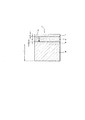
図1及び図2は、本発明による、高バルク音響共振器タイプの共振器2の一実施形態を示している。
1 and 2 show an embodiment of a
共振器2は、
−厚みe1を有するアルミニウムから形成された上側電極4と、
−第1の厚みt1を有する単結晶形の第1の材料、ここではニオブ酸リチウム(LiNbO3)から構成された圧電変換器6と、
−厚みe2を有する金から形成された埋込対向電極8と、
−第2の厚みt2を有する単結晶形の第2の材料、ここでは石英から構成された音響基板10と
を含む一連の層から成る堆積体を備えている。
The
An upper electrode 4 made of aluminum having a thickness e 1 ;
A piezoelectric transducer 6 composed of a single crystalline first material having a first thickness t 1 , here lithium niobate (LiNbO 3 );
An embedded
A deposit comprising a series of layers comprising a second material in the form of a single crystal having a second thickness t 2 , here an
図1の層4、6、8、10は全て同じ長さL及び幅Wを有し、長さLは幅Wよりも明らかに長く、またそれらの層は異なる厚さe1、t1、e2、t2を有している。
The
図1を簡単にするために、圧電変換器6の表面に等しい表面を有する上側電極4及び埋込対向電極8が示されている。
To simplify FIG. 1, the upper electrode 4 and the buried
実際には、上側電極4及び埋込対向電極8は、圧電変換器6の表面よりも小さな表面を有し、上側電極4は、埋込対向電極8の表面以下の表面を有する。
Actually, the upper electrode 4 and the embedded
接着層としての役割を果たす埋込層を設ける工程を含む製造方法では、埋込対向電極8は必然的に、リソグラフィ及び金属層堆積法によって製造される上側電極4の表面よりも大きな表面を有する。
In the manufacturing method including the step of providing a buried layer serving as an adhesive layer, the buried
上側電極4及び埋込対向電極8の表面は向かい合って、互いに平行に配置されており、それらの縁は可能な限り平行であり、それらの表面に面する個々のゾーンは最大である。理想的には、上側電極4及び埋込対向電極8の表面は完全に重ね合わせられる。
The surfaces of the upper electrode 4 and the buried
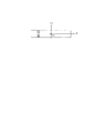
それゆえ、波の励起は、共振器のいわゆる平面−平面構成に対応すると仮定され、その構成の場合、波は、図2の矢印12によって示される圧電変換器6内の剪断波の伝搬方向において、圧電変換器6の両方の表面上に堆積された非常に薄い上側電極4及び埋込対向電極8によって励起される。
Therefore, the wave excitation is assumed to correspond to the so-called plane-to-plane configuration of the resonator, in which case the wave is in the propagation direction of the shear wave in the piezoelectric transducer 6 indicated by the arrow 12 in FIG. , Excited by a very thin upper electrode 4 and a buried
圧電変換器6は、ベクトルPAによって示される共振器の長さlに沿って向けられた偏波に従って励起される剪断モードを有している。 The piezoelectric transducer 6 has a shear mode is excited in accordance with polarization oriented along the length l of the resonator indicated by the vector P A.
音響基板10は、2つの剪断モード、すなわち、第1のモードである低速モードと、第2のモードである高速モードとを有している。
The
いわゆる高速剪断波及びいわゆる低速剪断波は直交偏波の剪断波と定義され、いわゆる高速波は、いわゆる低速波よりも速い位相速度を有する。 So-called fast shear waves and so-called slow shear waves are defined as orthogonally polarized shear waves, and so-called fast waves have a higher phase velocity than so-called slow waves.
図1において、圧電変換器6の剪断モードに対応する励起の偏波ベクトルPAは、音響基板の低速剪断モードに対応するPB1で指示された偏波ベクトルと整列する。 In Figure 1, the polarization vector P A of the excitation corresponding to a shear mode piezoelectric transducers 6 is aligned with the polarization vector is indicated by P B1 corresponding to the low-speed shear mode acoustic substrate.
PB1によって示されているベクトルに直交する高速剪断モードの励起に対応する偏波ベクトルは、図1において、PB1に直交するPB2によって示されており、音響基板10の伸長面内に含まれる。 The polarization vector corresponding to the high-speed shear mode excitation orthogonal to the vector indicated by P B1 is indicated by P B2 orthogonal to P B1 in FIG. It is.
圧電変換器6と音響基板10との間で熱圧縮された埋込対向電極8は、共振器2の構造への接着のためにも用いられる。
The embedded
圧電変換器6を構成するニオブ酸リチウム(LiNbO3)の層は、ウェーハを形成する単結晶原材料において第1の切断角θ1に沿って切り取られたプレートである。 The layer of lithium niobate (LiNbO 3 ) constituting the piezoelectric transducer 6 is a plate cut along the first cutting angle θ1 in the single crystal raw material forming the wafer.
音響基板10を構成する石英の層は、原料の単結晶石英ウェーハにおいて第2の切断角θ2に沿って切り取られたプレートである。
The quartz layer constituting the
図3によれば、ニオブ酸リチウムのプレートが、図示されていないが、結晶軸X1、Y1、Z1によって指示されたウェーハの材料から第1の切断角θ1に沿って切り取られる。ただし、結晶軸Z1はウェーハの縦軸であり、結晶軸X1、Y1は、単結晶の製造中に予め決定される。 According to FIG. 3, a lithium niobate plate is not shown, but is cut along the first cutting angle θ1 from the wafer material indicated by the crystal axes X 1 , Y 1 , Z 1 . However, the crystal axis Z 1 is the vertical axis of the wafer, and the crystal axes X 1 and Y 1 are determined in advance during the production of the single crystal.
ここでθ1は、IEEE Std−176(1949年版)標準規格において、結晶軸X1を中心にしたシングルローテーションカットの第1の切断角θ1と定義され、そのカットは、IEEE標準規格において(Y1Xl1)/θ1で表され、図3の例示によれば、Xl1は、直線の下側縁と整列する軸であり、そのカットの厚みはt1であり、長さはl1である。 Here, θ1 is defined as a first rotation angle θ1 of a single rotation cut around the crystal axis X 1 in the IEEE Std-176 (1949 edition) standard, and the cut is defined as (Y 1 X l1 ) / θ1, and according to the illustration of FIG. 3, X l1 is the axis that is aligned with the lower edge of the line, the thickness of the cut is t 1 and the length is l 1 .
切り取られるプレート6に関連する基準系は、3つの軸X’1、Y’1、Z’1によって示されており、軸X’1は結晶軸X1と組み合される。2つの軸Y’1、Z’1は、結晶軸X1を中心にして、結晶軸X1、Y1をそれぞれ回転角θ1だけ回転させることによって得られる。 Reference system associated with the plate 6 to be cut are three axes X '1, Y' 1, 'is indicated by 1, the axis X' Z 1 is combined with the crystal axis X 1. Two axes Y '1, Z' 1 is about the crystal axis X 1, obtained by the crystal axes X 1, Y 1 is rotated by the respective rotation angle .theta.1.
図4は、ニオブ酸リチウムからなる圧電変換器6の結晶軸Xl1を中心にしたシングルローテーションカットの場合の縦波及び剪断波の位相速度の変化を示している。 FIG. 4 shows changes in the phase velocity of the longitudinal wave and the shear wave in the case of a single rotation cut around the crystal axis X11 of the piezoelectric transducer 6 made of lithium niobate.
曲線14は、上側電極4及び埋込対向電極8の平面において垂直軸に沿って圧電変換器6内に伝搬する剪断波の位相速度を、第1の切断角θ1の関数として示している。
A curve 14 shows the phase velocity of the shear wave propagating into the piezoelectric transducer 6 along the vertical axis in the plane of the upper electrode 4 and the embedded
曲線16は、長さlの軸に沿って圧電変換器6内に広がる、km/s単位で表された縦波の位相速度を、度単位で表される第1の切断角θ1の関数として表している。
図5は、圧電変換器6の結晶軸X1を中心にしたシングルローテーションカットの場合の縦波及び剪断波の結合を示している。 FIG. 5 shows the coupling of the longitudinal wave and the shear wave in the case of a single rotation cut around the crystal axis X 1 of the piezoelectric transducer 6.
曲線18は、剪断波の場合に音響エネルギーに変換される電気エネルギーの割合として表された結合係数K2 Tの変化を、度単位で表される第1の切断角θ1の関数として示している。
曲線20は、縦波の場合に音響エネルギーに変換される電気エネルギーの割合として表された結合係数K2 Tの変化を、度単位で表される第1の切断角θ1の関数として示している。
図5は、曲線18及び20が、縦波が圧電気によって実際には結合されず、従って、圧電変換器6の電気的応答に寄与せず、剪断波の励起は特に有効であり、K2 Tによって示される電気機械的結合が50%〜60%である。 FIG. 5 shows that curves 18 and 20 do not actually cause the longitudinal wave to be coupled by piezoelectricity, and therefore do not contribute to the electrical response of the piezoelectric transducer 6, shear wave excitation is particularly effective, and K 2 The electromechanical coupling indicated by T is between 50% and 60%.
角度ゾーン22は、163度に等しい角度θ1を中心に、10度に等しい広がりを有している。
The
図1に示される圧電変換器の第1の切断角θ1は、163度に等しい図6の角度ゾーン22において選択される。
The first cutting angle θ1 of the piezoelectric transducer shown in FIG. 1 is selected in the
ニオブ酸リチウムのシングルローテーションカットの場合、高速剪断波に対応するモードだけが、圧電気による電気機械的結合を有する。図6において与えられる、平面軸X’1、Y’1に沿った圧電変換器6のプレートの平面図について考慮すると、圧電気によって励起される剪断モードは、図6において向こう側から示される、すなわち平面(X’1,Y’1)に対して垂直である、軸Z’1に沿ったスカラー偏波を有するが、その空間依存性は、励起面に基づいて空間座標の関数によって表されることが示される。偏波ベクトルPAは、軸Z’1と同一直線上にある。 In the case of a single rotation cut of lithium niobate, only the mode corresponding to the high-speed shear wave has electromechanical coupling by piezoelectricity. Considering the plan view of the plate of the piezoelectric transducer 6 along the plane axes X ′ 1 , Y ′ 1 given in FIG. 6, the shear mode excited by piezoelectricity is shown from the other side in FIG. That is, it has a scalar polarization along axis Z ′ 1 that is perpendicular to the plane (X ′ 1 , Y ′ 1 ), but its spatial dependence is expressed by a function of spatial coordinates based on the excitation plane. Is shown. The polarization vector P A is collinear with the axis Z ′ 1 .
図7によれば、石英プレート10は、図には示されないが、石英の結晶軸X2、Y2、Z2によって指示されるウェーハの単結晶原料から、第2の切断角θ2に沿って切り取られる。ただし、結晶軸Z2は、結晶宝石の成長中に現れる光学軸Cである。
According to FIG. 7, the
ここで、第2の切断角θ2は、IEEE Std−176(1949年版)標準規格において、結晶軸X2を中心にしたシングルローテーションカットの第2の切断角θ2と定義され、そのカットは、IEEE Std−176標準規格において(Y2Xl2)/θ2で表され、図4の例示によれば、Xl2は、直線の下縁に一致する軸であり、そのカットの厚みはt2であり、長さはL2である。 Here, in the IEEE Std-176 (1949 edition) standard, the second cutting angle θ2 is defined as a second cutting angle θ2 of a single rotation cut centered on the crystal axis X 2 , and the cut is defined as IEEE In the Std-176 standard, represented by (Y 2 X l2 ) / θ2, and according to the illustration of FIG. 4, X l2 is an axis that coincides with the lower edge of the straight line, and the thickness of the cut is t 2 and a length of L 2.
切り取られる石英プレート10に関連する基準系は、3つの軸X’2、Y’2、Z’2によって示されており、軸X’2は、結晶軸X2と組み合わされる。2つの軸Y’2、Z’2は、結晶軸X2を中心にして、結晶軸Y2、Z2をそれぞれ回転角θ2だけ回転させることによって得られる。
Reference system associated with the
図6の圧電変換器6に関して与えられる平面図と同じような、図8において与えられる石英プレート10の軸X’2、Y’2に沿った平面図を考慮すると、一次の波の熱感度または二次の波の熱感度でさえ相殺する、石英において利用したい剪断モードの偏波を、記号を変更することなく示すことができる。石英の場合の剪断もスカラーであるが、その剪断は軸X’2に沿って確立され、励起面に基づいてプレートに結び付けられる局部座標に依存する。それゆえ、IEEE標準規格表記1949年版(圧電気の規格についてのIEEE規格(IEEE standard on piezoelectricity Std.) 176頁,1949年(176-1949), 通信学会誌(Proc. of the IRE) 37巻、 1378〜1395頁、1949年)に従って(XY1/θ)で表されるシングルローテーションニオブ酸リチウム又はタンタル酸リチウムプレートの場合、選択される剪断波は、互いに直交する偏波を有し、圧電変換器6及び音響基板の結晶軸が適切に整列する場合のみ結合する。音響基板10、ここでは石英において励起したい音響波を結合できるようにするために、これらの偏波を、圧電変換器及び音響基板の材料の組立中に考慮しなければならない。
Considering the plan view along the axes X ′ 2 , Y ′ 2 of the
ここで、圧電変換器6の励起モードの偏波PAがPB1によって示される音響基板10内の剪断モードの偏波と同じになることにより、対応する波の位相速度の熱ドリフトを相殺できるように、音響基板10の軸X’2に圧電変換器6の軸Z’1を整列させるか、又は同じく音響基板10の軸Z’2に圧電変換器6の軸X’1を整列させることによって、この音響結合効果が得られる。
Here, the polarization P A of the excitation mode of the piezoelectric transducer 6 becomes the same as the polarization of the shear mode in the
図9は、静的な熱作用に対する石英の剪断モードの感度を、度単位で表される第2の切断角θ2の関数として示している。この感度は、ppm.K-1単位(ケルビン当たりの周波数のppm)で表され、図1に類似の平面−平面音響基板10の場合の互いに直交する一定の偏波に対応する2つの一次の周波数温度係数CTFB1及びCTFB2の形をとる。
FIG. 9 shows the sensitivity of the quartz shear mode to static thermal action as a function of the second cutting angle θ2 expressed in degrees. This sensitivity is in ppm. Two first-order frequency temperature coefficients CTFB1 and CTFB2 expressed in K -1 units (ppm of frequency per Kelvin) and corresponding to constant polarizations orthogonal to each other in the case of a plane-plane
実線の第1の曲線30は、先行する波に直交して偏向した剪断波の場合の第1の一次の周波数温度係数CTFB1の変化を、第2の切断角θ2の関数として示しており、それらの偏向は、図1のベクトルPB1に対応する。
The solid
破線の第2の曲線32は、先行する波に直交して偏向した剪断波の場合の第2の一次の周波数温度係数CTFB2の変化を、第2の切断角θ2の関数として示しており、それらの偏向は、図1のベクトルPB2に対応する。
A dashed
いわゆる高速モード剪断波及びいわゆる低速モード剪断波は、直交偏波を有する剪断波と定義され、いわゆる高速波は、いわゆる低速波よりも速い位相速度を有する。 So-called fast mode shear waves and so-called slow mode shear waves are defined as shear waves with orthogonal polarization, so-called fast waves have a faster phase velocity than so-called slow waves.
石英の場合、−24度に等しい第2の切断角θ2の付近において、低速モード及び高速モードが偏波を交換する。それらのモードは直交したままであるが、−24度〜−90度の第2の切断角θ2を有するカットの場合に、高速剪断モードが低速剪断モードに取って代わる。曲線30及び32が一定のCTFB1及びCTFB2で図示されているが高速剪断モードまたは低速剪断モードによって図示されていないので、この現象は図8において見ることができない。
In the case of quartz, the low speed mode and the high speed mode exchange polarization in the vicinity of the second cutting angle θ2 equal to −24 degrees. The modes remain orthogonal, but the high shear mode replaces the low shear mode for cuts having a second cut angle θ2 of −24 degrees to −90 degrees. This phenomenon cannot be seen in FIG. 8 because
−24度と+90度との間のθ2の場合、X2に沿った偏波は低速剪断波に対応するのに対して、−90度と−24度との間のθ2の場合、X2に沿った偏波は高速剪断波に対応する。 For θ2 between −24 degrees and +90 degrees, the polarization along X 2 corresponds to a slow shear wave, whereas for θ2 between −90 degrees and −24 degrees, X 2 The polarization along the line corresponds to a high-speed shear wave.
曲線30は、2つの角度ゾーン34、36の存在を示しており、各角度ゾーンにはそれぞれ、軸X’2に沿って偏波した剪断波に対する一次の周波数温度係数CTFB1を相殺するための、θ2nul1及びθ2nul2で示される角度の値が存在する。
ATカット群とも呼ばれる角度ゾーン36の場合、35度と36度との間において、二次の周波数温度係数を相殺できるようにする非常に正確な第2の切断角θ2を得ることができ、その際、温度の関数としての周波数のドリフトは3乗の変化則に従う。
In the case of the
角度ゾーン34の場合、一次の周波数温度係数しか相殺することはできないが、BTと呼ばれる従来のカット群は、ATカット群で達成可能な値よりも良好な共振品質値を有することが知られている。
In the case of
石英の場合、θ2nul1及びθ2nul2はそれぞれ、−42度及び+35度に等しい。 In the case of quartz, θ2nul1 and θ2nul2 are equal to −42 degrees and +35 degrees, respectively.
θ2nul1を中心にした第1の角度ゾーン34は20度の広がり、好ましくは10度の広がりを有し、その範囲では、曲線30は、正の傾きを有する線分になぞらえることができる。
The
θ2nul2を中心にした第2の角度ゾーン36も20度の広がり、好ましくは10度の広がりを有し、その範囲では、曲線30は、負の傾きを有する線分になぞらえることができる。
The
図1の圧電変換器の第1の切断角θ1は、角度ゾーン22において選択される。
The first
音響基板10の第2の切断角θ2は、角度ゾーン34又は36のうちの一方の部分において選択され、その場合、CTFA係数が負であるという事実を考慮に入れて、CTFB1は0又は正である。
The second cutting angle θ2 of the
ATカット群、すなわち、角度ゾーン36内にあり、かつ35度に等しいことが好ましいθ2の場合に、ニオブ酸リチウムの厚みが石英の厚みよりもはるかに薄い、すなわち、ニオブ酸塩/石英の厚みの比が2%未満である場合、検出されるほど十分に結合された第1のモードは、石英によって温度効果を完全に補償される。一次のCTFRで知られている共振器の温度感度は、約1ppb.K-2の二次の周波数温度係数の場合に、1ppm.K-1未満である。
In the AT cut group, ie, θ2, which is in the
しかし、最大の電気機械的結合を有するモードの場合、共振器の一次の温度感度の絶対値において、突然の増加が観測される。この現象は、そのモードを励起するのに有用なエネルギーが、ニオブ酸リチウム内で結合される波の速度を2で割って、ニオブ酸塩の層の厚みを掛けた値に近い周波数のための最大値に達するまで、石英内よりもニオブ酸塩の層において常に大きいという事実によって説明され、そのモードは、圧電変換器単体の層の基本モードに対応する。その際、結果として生成される共振器のモードは、エネルギーが主に石英内に局在するモードよりも、圧電変換器及び電極によって形成された励起層の特性の影響を受けやすい。しかしながら、共振器の一次の温度感度CTFRは、圧電変換器単体の一次の温度感度値CTFAに達することはなく、石英のカットを調整することによって、共振器の感度の値を最小限に抑えられるようになる。 However, for the mode with maximum electromechanical coupling, a sudden increase in the absolute value of the first order temperature sensitivity of the resonator is observed. This phenomenon is useful for frequencies close to the energy useful to excite that mode divided by the velocity of the wave coupled in lithium niobate divided by the thickness of the niobate layer. Explained by the fact that it is always larger in the niobate layer than in quartz until the maximum value is reached, the mode corresponds to the fundamental mode of the layer of piezoelectric transducer alone. In that case, the resulting mode of the resonator is more sensitive to the properties of the excitation layer formed by the piezoelectric transducer and the electrode than the mode in which the energy is mainly localized in the quartz. However, the primary temperature sensitivity CTFR of the resonator does not reach the primary temperature sensitivity value CTFA of the piezoelectric transducer alone, and the sensitivity value of the resonator can be minimized by adjusting the quartz cut. It becomes like this.
−90ppm.K-1付近における圧電変換器6単体の一次の温度感度の計算値と、概ね0ppm.K-1における石英の感度の値とについて考えると、最適な結合モードの場合に共振器から生じる一次のCTFRの値は、以下の式に従って、圧電変換器の一次の周波数温度係数及び音響基板の一次の周波数温度係数の重み付けされた和として求めることができる。
CTFR=CTFB1(石英)+CTFA(ニオブ酸塩)*Y(%)
-90 ppm. The calculated value of the primary temperature sensitivity of the piezoelectric transducer 6 alone in the vicinity of K −1 and approximately 0 ppm. Considering the value of the sensitivity of quartz at K −1, the value of the first order CTFR generated from the resonator in the case of the optimal coupling mode is the primary frequency temperature coefficient of the piezoelectric transducer and the acoustic substrate according to the following equation: It can be determined as a weighted sum of first order frequency temperature coefficients.
CTFR = CTFB1 (quartz) + CTFA (niobate) * Y (%)
パーセンテージとして表される係数Yは、1/50、2.5/50、5/50に等しいニオブ酸塩/石英の厚みの比の場合にそれぞれ、6、10、15に等しく、その厚みは概ね、1μm又は数μmである。最も強く結合されるモードの温度効果の補償を得るために、石英のCTFB1はそれぞれ、+5、+10、+15ppm.K-1に等しくなければならない。 The factor Y, expressed as a percentage, is equal to 6, 10 and 15 for niobate / quartz thickness ratios equal to 1/50, 2.5 / 50 and 5/50, respectively, and the thickness is approximately 1 μm or several μm. To obtain compensation for the temperature effect of the most strongly coupled mode, the quartz CTFB1 is +5, +10, +15 ppm. Must be equal to K- 1 .
10/50及び20/50に等しいニオブ酸塩/石英の厚みの比Reの場合に、Yの値が22%及び32%であることがわかる。 It can be seen that the value of Y is 22% and 32% for a niobate / quartz thickness ratio Re equal to 10/50 and 20/50.
Reの関数としての最も強い結合時のモードのCTFRの分布は、以下の法則に従う。
CTFR=0.85×Re+3.2×log(4×50×Re)
ただし、
Reは、圧電変換器の厚みを音響基板の厚みで割った比を示し、
logは自然対数関数であり、厚みは暗にμmであり、CTFRはppm.K-1で表される。
The distribution of CTFR of the strongest coupling mode as a function of Re follows the following law.
CTFR = 0.85 × Re + 3.2 × log (4 × 50 × Re)
However,
Re represents the ratio of the thickness of the piezoelectric transducer divided by the thickness of the acoustic substrate,
log is a natural logarithmic function, the thickness is implicitly μm, and the CTFR is ppm. It is represented by K- 1 .
式:CTFB1=(θ2−35)*5.10-6によって、+35度(ATカット)に等しいθ2の近くに表される、結晶軸X2を中心とした第2の切断角θ2の関数としての石英単体のCTFB1の変化と、CTFTの分布式とから、最も強い結合モードの温度効果を補償できるようにする、θ2corで示される補正された第2の切断角θ2は、式0.85×Re+3.2×log(4×50×Re)=(θ2cor−35)*5.10-6によって求められる。この式に基づいて、1/50、2.5/50、5/50の厚みの比の場合にそれぞれ、34、33、32に等しい第2の切断角θ2を有するカットXY1/θ2が用いられる。こうして、第2の切断角θ2は、共振器の結合モードの高調波次数及びATカットの場合のニオブ酸塩/石英の厚みの比の関数として調整される。このようにして得られた温度ドリフトの補償は、一次及び二次から成る。 As a function of the second cutting angle θ2, centered on the crystal axis X2, represented by the formula: CTFB1 = (θ2−35) * 5.10 −6 and near θ2 equal to +35 degrees (AT cut). The corrected second cutting angle θ2 indicated by θ2cor that makes it possible to compensate for the temperature effect of the strongest coupling mode from the change in CTFB1 of quartz alone and the distribution equation of CTFT is expressed by the equation 0.85 × Re + 3. 2 × log (4 × 50 × Re) = (θ2cor−35) * 5.10 −6 Based on this equation, cuts XY1 / θ2 having a second cutting angle θ2 equal to 34, 33, 32 are used for thickness ratios of 1/50, 2.5 / 50, 5/50, respectively. . Thus, the second cutting angle θ2 is adjusted as a function of the harmonic order of the resonator coupling mode and the ratio of niobate / quartz thickness in the case of AT cut. The temperature drift compensation obtained in this way consists of a primary and a secondary.
ここで、石英のATカット(35度に等しいθ2)及びそれに近いカットをBTカット(−48度に等しい第2の切断角θ2に近い角度ゾーン34内)で置き換える場合には、ATカットの挙動に類似の挙動が観測される。
Here, when the quartz AT cut (θ2 equal to 35 degrees) and the cut close thereto are replaced with the BT cut (in the
第1のモードの結合がそれほど強くない場合、共振器のCTFRは、石英のCTFB1に完全に等しく、その補償は、BTカットの場合にのみ一次から成る。 If the first mode coupling is not very strong, the resonator's CTFR is exactly equal to quartz's CTFB1, and its compensation consists of the first order only in the case of the BT cut.
最大の結合モードの場合、共振器のCTFRは高くなり、ATカットの場合に観測されるCTFRに近くなる。1/50、2.5/50、5/50の厚みの比Reの場合の共振器の一次のCTFR値はそれぞれ、−6ppm.K-1、−11ppm.K-1、−16ppm.K-1に等しい。 For the maximum coupling mode, the CTFR of the resonator is high and close to the CTFR observed for AT cuts. The primary CTFR values of the resonators at the thickness ratio Re of 1/50, 2.5 / 50, and 5/50 are -6 ppm. K < -1 >, -11 ppm. K < -1 >, -16 ppm. Equal to K- 1 .
CTFR=CTFB1(石英)+CTFA(ニオブ酸塩)*Y(%)
の式に従って、圧電変換器の一次の周波数温度係数と音響基板の一次の周波数温度係数との重み付けされた和として、最適な結合モードの場合の共振器から生じる一次のCTFRの値を表す関係に戻ると、ATカットの場合に観測されるのに類似の一連の数に対応する厚みの比Re1/50、2.5/50、5/50の場合にそれぞれ、Yは約7、12、17であることがわかる。
CTFR = CTFB1 (quartz) + CTFA (niobate) * Y (%)
In accordance with the following equation, the relationship between the first-order frequency temperature coefficient of the piezoelectric transducer and the first-order frequency temperature coefficient of the acoustic substrate represents the value of the first-order CTFR generated from the resonator in the optimum coupling mode. Returning, Y is about 7, 12, 17 for thickness ratios Re1 / 50, 2.5 / 50, 5/50 corresponding to a series of numbers similar to those observed for AT cuts, respectively. It can be seen that it is.
BTカット(−42度に等しいθ2)の付近において、石英のCTFB1の変化は、法則CTFB1=(θ2+42)*2.2.10-6によって都合よく近似される。 In the vicinity of the BT cut (θ2 equal to −42 degrees), the change in CTFB1 of the quartz is conveniently approximated by the law CTFB1 = (θ2 + 42) * 2.2.10 −6 .
カットYX1/θ2の補正された第2の切断角θ2は、それぞれの厚みの比Reが1/50、2.5/50、5/50の場合に、−45、−43、−41に等しくなるように計算される。 The corrected second cutting angle θ2 of the cut YX1 / θ2 is equal to −45, −43, and −41 when the thickness ratio Re is 1/50, 2.5 / 50, and 5/50, respectively. Is calculated as follows.
ATカットの場合に決定されるニオブ酸塩/石英の厚みの比の関数としての共振器の最も強い結合モードのCTF1の分布則は、BTカットの場合にも一定の範囲内で適用可能である。その分布則は、CTFR=1.25×50×Re+3.2×log(4×50×Re)で表され、温度効果の最良の結合モードを補償するために、ニオブ酸塩/石英の厚みの比及び石英の第2の切断角θ2を調整することを含むとき、設計手順を一般化できるようになる。 The strongest coupled mode CTF1 distribution law of the resonator as a function of the niobate / quartz thickness ratio determined in the case of the AT cut is also applicable within a certain range in the case of the BT cut. . The distribution law is expressed as CTFR = 1.25 × 50 × Re + 3.2 × log (4 × 50 × Re), and the thickness of niobate / quartz is compensated to compensate for the best coupling mode of the temperature effect. The design procedure can be generalized when including adjusting the ratio and the second cutting angle θ2 of the quartz.
ここで得られた結果は、ニオブ酸塩及び石英の層の厚みに関係なく置き換えることができる。詳細には、共振モード間の間隔が、圧電変換器及び音響基板によって形成された堆積体の全厚みに依存する場合には、厚みの比Reのみが、その高調波次数の関数として、共振モードの一次のCTFRを決定する。 The results obtained here can be replaced regardless of the thickness of the niobate and quartz layers. In particular, if the spacing between the resonant modes depends on the total thickness of the deposit formed by the piezoelectric transducer and the acoustic substrate, only the thickness ratio Re is a function of its harmonic order as a function of its harmonic order. Determine the first order CTFR.
このようにして、温度補償されたHBARタイプの共振器構造を形成することができ、その構造では、共振器が所望の同調周波数において共振するように、圧電変換器の幾何学的寸法が決定される。 In this way, a temperature compensated HBAR type resonator structure can be formed, where the geometry of the piezoelectric transducer is determined such that the resonator resonates at a desired tuning frequency. The
圧電変換器の幾何学的寸法は、用途の動作要件から生じるさらなる電気的特性を満たしながら、共振器が所望の同調周波数において共振するように決定される。 The geometric dimensions of the piezoelectric transducer are determined so that the resonator will resonate at the desired tuning frequency while meeting additional electrical characteristics resulting from the operational requirements of the application.
さらなる電気的特性は、たとえば、他の共振がない共振モード周辺のスペクトルゾーンとして定義される2つの共振モード間のスペクトル分離と、選択された共振モードの電気機械的結合の効率と、共振の特性インピーダンスと、共振時の品質係数と、共振モードの熱安定性とである。 Further electrical characteristics include, for example, spectral separation between two resonant modes defined as a spectral zone around a resonant mode without other resonances, electromechanical coupling efficiency of the selected resonant mode, and resonant characteristics. Impedance, quality factor at resonance, and thermal stability of the resonance mode.
スペクトル分離は、埋込対向電極を含む圧電変換器及び音響基板によって形成されたアセンブリの基本モードの周波数に対応するので、スペクトル分離は、HBARタイプの共振器の層の堆積体の全厚みを決定できるようにする。 Since the spectral separation corresponds to the fundamental mode frequency of the assembly formed by the piezoelectric transducer and the acoustic substrate including the embedded counter electrode, the spectral separation determines the total thickness of the layer stack of the HBAR type resonator. It can be so.
異なる材料によって形成されたHBARタイプの共振器の各層の厚みは、所望の共振又は同調周波数のモードが得られるように調整される。 The thickness of each layer of an HBAR type resonator formed of different materials is adjusted to obtain the desired resonant or tuning frequency mode.
また、圧電変換器の厚みは、所望の電気機械的結合を考慮に入れて決定される。その結合は、選択されたモードが圧電変換器単体の共振の基本モードに近いときに最大である。 Also, the thickness of the piezoelectric transducer is determined taking into account the desired electromechanical coupling. The coupling is maximum when the selected mode is close to the fundamental mode of resonance of the piezoelectric transducer alone.
圧電変換器/音響基板の厚みの比は、目標とする共振の所望の熱安定性及び品質係数の関数として調整され、共振時に品質パラメーターの性能を確実に達成するために、用いられる材料の粘弾性定数、又は、たとえば、誘電率のような物理的特性を表す複素数値を有する他の物理係数を十分に知る必要があることがわかっている。これらの定数の虚数部は多くの場合に、帰納的に又は予測モデルのパラメーターを調整することによって決定される。 The thickness ratio of the piezoelectric transducer / acoustic substrate is adjusted as a function of the desired thermal stability and quality factor of the target resonance, and the viscosity of the material used is used to ensure that the quality parameter performance is achieved at resonance. It has been found necessary to fully know the elastic constants, or other physical coefficients having complex values representing physical properties such as, for example, dielectric constant. The imaginary part of these constants is often determined inductively or by adjusting the parameters of the predictive model.
共振時のインピーダンスは、選択されたモードの電気機械的結合と、向かい合う電極表面の値とに依存する。所与のインピーダンス、たとえば50オームの場合、選択されたモードの電気機械的結合が弱いほど、電極の向かい合う表面が大きくなる。 The impedance at resonance depends on the electromechanical coupling of the selected mode and the value of the opposing electrode surfaces. For a given impedance, for example 50 ohms, the weaker the electromechanical coupling of the selected mode, the larger the opposing surface of the electrodes.
堆積された厚みが1mm〜数μmである場合に、典型的な電極表面は数百μm2〜数mm2である。 Typical electrode surfaces are several hundred μm 2 to several mm 2 when the deposited thickness is 1 mm to several μm.
圧電変換器6の電気音響的振動の結合は、埋込対向電極8を通してなされ、埋込対向電極8は、圧電変換器6の帯域通過において音響的な短絡回路としての役割を果たす。
The electroacoustic vibration of the piezoelectric transducer 6 is coupled through the embedded
したがって、音響基板10は、自らの共振モードにおいて圧電変換器6の共振モードに従属し、それにより、圧電変換器6の共振モードに大きな温度安定性を与える。圧電変換器6が独立したままなら、著しくドリフトするであろう。実際には、HBAR圧電変換器の一次の周波数温度係数は高い値を有し、たとえば、ニオブ酸リチウムの場合には−80ppm.K-1〜−95ppm.K-1であり、タンタル酸リチウムの場合には−35ppm.K-1〜−50ppm.K-1である。
Therefore, the
したがって、このように従属される圧電変換器6の共振モードの温度安定性は、第2の切断角θ2の調整則と、共振モードの高調波次数と、共振器の圧電変換器/音響基板の厚みの比Reとを考慮に入れて、第2の切断角θ2を通して選択された周波数温度係数CTFB1の値と、圧電変換器6の剪断モード及び石英10の結合された剪断モードにそれぞれ対応する偏波ベクトルPA、PB1の整列とに対応する温度安定性である。
Therefore, the temperature stability of the resonance mode of the piezoelectric transducer 6 thus subordinated depends on the adjustment rule of the second cutting angle θ2, the harmonic order of the resonance mode, and the piezoelectric transducer / acoustic substrate of the resonator. Taking into account the thickness ratio Re, the value of the frequency temperature coefficient CTFB1 selected through the second cutting angle θ2 and the bias corresponding to the shear mode of the piezoelectric transducer 6 and the combined shear mode of the
図10は、本発明による、共振器の温度安定性能の一例を示している。 FIG. 10 shows an example of the temperature stability performance of the resonator according to the present invention.
圧電変換器6の周波数ドリフトが完全に補償される公称動作温度は50℃に等しいことが図8において明らかである。従来、空間電子装置の公称動作温度は、20℃〜60℃である。 It can be seen in FIG. 8 that the nominal operating temperature at which the frequency drift of the piezoelectric transducer 6 is fully compensated is equal to 50 ° C. Conventionally, the nominal operating temperature of space electronic devices is 20 ° C to 60 ° C.
共振器の公称動作温度は、−273℃から石英のキュリー温度(+575℃)まで難なく調整することができる。 The nominal operating temperature of the resonator can be adjusted without difficulty from -273 ° C to the Curie temperature of quartz (+ 575 ° C).
実際には、動作温度範囲は、液体ヘリウム又は液体窒素の温度(極低温基準)から+400℃までの範囲である。 In practice, the operating temperature range is from liquid helium or liquid nitrogen temperature (cryogenic reference) to + 400 ° C.
極端な温度における接着の完全性は依然として有効であるが、そのような装置の強度は、液体窒素に対応する低温から200℃までにおいて確認されている。 While integrity of adhesion at extreme temperatures is still effective, the strength of such devices has been confirmed from low temperatures up to 200 ° C. corresponding to liquid nitrogen.
ここで図8において、共振周波数の変動及び共振器の通過帯域幅を指示する反共振周波数の変動は、1ppm.K-1未満である。 Here, in FIG. 8, the fluctuation of the resonance frequency and the fluctuation of the anti-resonance frequency indicating the passband width of the resonator are 1 ppm. It is less than K- 1 .
図11は、本発明による図1の共振器2を製造するための方法100のフローチャートを示している。
FIG. 11 shows a flowchart of a
第1のステップ102では、圧電変換器6が準備され、圧電変換器6は、第1の材料から成る第1の厚みの層によって形成され、その層は、剪断波の電気音響的結合が5%よりも大きくなるように、0に等しいIEEE Std−176(1949年版)標準規格の用語(YXw)/φによって定義される角度φに沿って向けられ、かつIEEE Std−176(1949年版)標準規格の用語(YX1)/θによって定義される第1の切断角θ1に沿って切断され、圧電変換器6は、第1の切断角θ1の関数としての周波数温度係数CTFAを有する。
In a
圧電変換器6の材料は、窒化アンモニウム(AlN)、酸化亜鉛(ZnO)、ニオブ酸リチウム(LiNbO3)、タンタル酸リチウム(LiTaO3)、ニオブ酸カリウムから構成された材料群に含まれる。 The material of the piezoelectric transducer 6 is included in a material group composed of ammonium nitride (AlN), zinc oxide (ZnO), lithium niobate (LiNbO 3 ), lithium tantalate (LiTaO 3 ), and potassium niobate.
かなり厚みのある単結晶を製造するための方法を使いこなすのが容易であることに起因して、ニオブ酸リチウム(LiNbO3)及びタンタル酸リチウム(LiTaO3)の中から材料が選択されることが好ましい。 The choice of materials from lithium niobate (LiNbO 3 ) and lithium tantalate (LiTaO 3 ) due to the ease of mastering the process for producing fairly thick single crystals. preferable.
ニオブ酸リチウム及びタンタル酸リチウムは、500μm及び350μmの厚みの標準値によれば、10.16cm(4インチ)の直径を有するウェーハによって製造することができる。 Lithium niobate and lithium tantalate can be produced by wafers having a diameter of 10.16 cm (4 inches) according to standard values of thicknesses of 500 μm and 350 μm.
第2のステップ104では、音響基板10が準備され、音響基板は、第2の材料から成る第2の厚みの層から構成され、その層は、5.1012に少なくとも等しい動作周波数及び音響品質係数の積を有し、0に等しいIEEE Std−176(1949年版)標準規格の用語(YXw)/φによって定義される角度φに沿って向けられ、IEEE Std−176(1949年版)標準規格の用語(YX1)/θによって定義される第2の切断角θ2に沿って切断され、剪断振動モードに対応する少なくとも1つの偏波方向PB1を有し、音響基板10は、少なくとも1つの剪断モードに対応し、かつ第2の切断角θ2に依存する一次の周波数温度係数CTFB1を有する。
In a
ステップ104では、音響基板10の第2の切断角θ2は、第1の厚みを前記第2の厚みで割った比が0.02未満であるときに、少なくとも1つの剪断モード及び第2の切断角θ2に対応する一次の温度係数CTFB1が0であるか、又は第1の厚みを第2の厚みで割った比が0.02以上であるときに、その比の増加関数によって重み付けされた圧電変換器6の周波数温度係数CTFAの反対符号の値に等しくなるような角度である。
In
音響基板の材料は、石英と、たとえばGeO2タイプ及びTeO2タイプの同形置換体と、オルトリン酸ガリウム(GaPO4)及びその同形構造体と、ニオブ酸カリウムと、四ホウ酸リチウム(Li4BO7)と、ランガサイト(La3Ga5SiO14)と、ランガテイトと、ランガサイトと、それらの種々の変形とから構成された材料群に含まれる。 The material of the acoustic substrate is quartz, for example, GeO 2 type and TeO 2 type isomorphous substitutes, gallium orthophosphate (GaPO 4 ) and its isomorphous structure, potassium niobate, and lithium tetraborate (Li 4 BO 7 ). , Langasite (La 3 Ga 5 SiO 14 ), langate, langasite, and various modifications thereof.
音響基板の材料は、その優れた温度安定性及び結晶学分野におけるその完全な知識に起因して、石英であることが好ましい。 The material of the acoustic substrate is preferably quartz due to its excellent temperature stability and its complete knowledge in the field of crystallography.
後続のステップ106では、2つの面を接着して対向電極を形成するために、熱圧縮性材料又は冷間圧縮性材料、たとえば、金、銅又はインジウムによって、圧電変換器6の1つの面及び音響基板10の1つの面が、100nm〜200nmの厚みまで金属化される。
In a
圧電変換器6と音響基板10との間の音響的結合を確実にするだけの十分な可塑性及び機械的強度を考えると、金が、このタイプの接着にとって特に良好な材料である。
Gold is a particularly good material for this type of adhesion given the sufficient plasticity and mechanical strength to ensure an acoustic coupling between the piezoelectric transducer 6 and the
組立ステップ108では、第1の切断角θ1に対応する圧電変換器6の剪断モードの偏波方向PA及び第2の切断角θ2に対応する音響基板10の少なくとも1つの剪断モードの偏波方向PB1が整列するように、圧電変換器6及び音響基板10が配列される。
In assembling
後続のステップ110では、用いられる金属に応じて、温度を上げて又は上げることなく圧縮することによって、接着が行なわれる。
In a
金が用いられる場合、向かい合う表面の品質を保持すると共に金属材料の延性を用いて接着を確実にするために、加熱過程を無くし、長期にわたる加圧が実施される。 When gold is used, the heating process is eliminated and long-term pressurization is performed to maintain the quality of the opposing surfaces and to ensure adhesion using the ductility of the metal material.
このようにして、3000ニュートンの圧力をかけながら16時間、30℃の温度を保持するだけで、欠陥を生じることなく、いくつかのニオブ酸リチウム/石英複合材料スライスを製造することができた。 In this way, several lithium niobate / quartz composite slices could be produced without defects by simply maintaining a temperature of 30 ° C. for 16 hours while applying a pressure of 3000 Newtons.
次にステップ112では、共振器のスライスのバーンインが実施され、研磨される。
Next, in
その後、ステップ114では、音響基板の反対側にある圧電変換器6の面において電極が、例えばアルミニウムによって金属化される。
Thereafter, in
この方法は、実施するのが容易であり、良好な温度安定性能を得ることを可能にする。 This method is easy to implement and makes it possible to obtain good temperature stability performance.
さらに、この方法を用いて得られる共振器は、20GHzまでの周波数において動作することができる。その共振器は軽量であり、しかも嵩張らないので、高い集積度を提供する。 Furthermore, resonators obtained using this method can operate at frequencies up to 20 GHz. The resonator is lightweight and not bulky, thus providing a high degree of integration.
そのような共振器は、たとえば、ホモダイン発振器又は高除去フィルターのセルに集積することができる。 Such a resonator can be integrated, for example, in a homodyne oscillator or a high rejection filter cell.
当然、他の応用例を考えることもできる。 Of course, other application examples can be considered.
Claims (16)
第1の材料から成る第1の厚みを有する層によって形成された圧電変換器(6)であって、前記第1の材料単体内の剪断波の電気音響的結合が5%よりも大きくなるように、0に等しいIEEE Std−174(1949年版)標準規格の用語(YXw)/φによって定義される角度φに沿って向けられ、IEEE Std−176(1949年版)標準規格の用語(YX1)/θによって定義される第1の切断角θ1に沿って切断され、前記第1の切断角θ1の関数としての一次の周波数温度係数CTFAを有する圧電変換器と、
第2の材料から成る第2の厚みを有する第2の層によって形成された音響基板(10)であって、少なくとも5.1012に等しい動作周波数及び音響品質係数の積を有し、0に等しいIEEE Std−176(1949年版)標準規格の用語(YXw)/φによって定義される角度φに沿って向けられ、IEEE Std−176(1949年版)標準規格の用語(YX1)/θによって定義される第2の切断角θ2に沿って切断され、剪断振動モードに対応する少なくとも1つの偏波方向PB1を有し、前記少なくとも1つの剪断モードに対応すると共に前記第2の切断角θ2に依存する一次の周波数温度係数CTFB1を有する音響基板と、
前記圧電変換器(6)の第1の面及び前記音響基板(10)の1つの面に接着する金属層によって形成された対向電極(8)と、
前記圧電変換器(6)の前記第1の面及び前記音響基板(10)から離れる方に面する、前記圧電変換器(6)の第2の面上に配置された上側電極(4)と
を備え、
前記第1の切断角θ1に対応する前記圧電変換器(6)の前記剪断モードの偏波方向PAと、前記第2の切断角θ2に対応する前記音響基板(10)の前記少なくとも1つの剪断モードの前記偏波方向PB1とが整列するように、前記圧電変換器(6)及び前記音響基板(10)が相対的に配列されることと、
前記音響基板(10)の前記第2の切断角θ2は、前記第1の厚みを前記第2の厚みで割った比が0.02未満であるときに、前記少なくとも1つの剪断モード及び前記第2の切断角θ2に対応する前記一次の周波数温度係数CTFB1が0であるか、又は前記第1の厚みを前記第2の厚みで割った比が0.02以上であるときに、前記一次の周波数温度係数CTFB1が、該比の増加関数によって重み付けされる前記圧電変換器(6)の前記周波数温度係数CTFAの反対符号の値に等しくなるような角度であることと
を特徴とする高バルク音響共振器タイプの共振器。 A high bulk acoustic resonator type resonator for operating at a predetermined operating frequency,
A piezoelectric transducer (6) formed of a first material layer having a first thickness, wherein the electroacoustic coupling of shear waves in the first material alone is greater than 5%. Is oriented along an angle φ defined by IEEE Std-174 (1949) standard term (YXw) / φ equal to 0, and IEEE Std-176 (1949 version) standard term (YX1) / a piezoelectric transducer cut along a first cutting angle θ1 defined by θ and having a first-order frequency temperature coefficient CTFA as a function of the first cutting angle θ1;
An acoustic substrate (10) formed by a second layer of a second material having a second thickness, the product having an operating frequency and an acoustic quality factor equal to at least 5.10 12 Directed along an angle φ defined by equal IEEE Std-176 (1949) standard term (YXw) / φ and defined by IEEE Std-176 (1949) standard term (YX1) / θ And having at least one polarization direction P B1 corresponding to the shear vibration mode and corresponding to the at least one shear mode and depending on the second cut angle θ2. An acoustic substrate having a primary frequency temperature coefficient CTFB1
A counter electrode (8) formed by a metal layer bonded to the first surface of the piezoelectric transducer (6) and one surface of the acoustic substrate (10);
An upper electrode (4) disposed on a second surface of the piezoelectric transducer (6) facing away from the first surface of the piezoelectric transducer (6) and the acoustic substrate (10); With
A polarization direction P A of said shear mode piezoelectric transducers (6) corresponding to the first cutting angle .theta.1, wherein at least one of the acoustic substrate corresponding to the second cutting angle .theta.2 (10) The piezoelectric transducer (6) and the acoustic substrate (10) are relatively arranged so that the polarization direction P B1 of the shear mode is aligned;
When the ratio of the first thickness divided by the second thickness is less than 0.02, the second cutting angle θ2 of the acoustic substrate (10) is the at least one shear mode and the first whether the corresponding to the second cutting angle θ2 primary temperature coefficient of frequency CTFB1 is 0, or when the first ratio and the thickness divided by the thickness of the second is 0.02 or more, of the primary High bulk acoustics characterized in that the frequency temperature coefficient CTFB1 is at an angle equal to the value of the opposite sign of the frequency temperature coefficient CTFA of the piezoelectric transducer (6) weighted by the increasing function of the ratio Resonator type resonator.
α.Re+β.log(γ.Re)=(θ2−θ2nul)*slope
の形の関係を検査し、
θ2nulは、前記一次の周波数温度係数CTFB1が相殺すると共に符号を変更する第2の切断角の値であり、
slopeは、θ2nulにおいて得られるθ2に対するCTFB1の傾きであり、
α、β、γは、前記音響基板(10)及び前記圧電変換器(6)を構成する材料の種類に依存する定数であることを特徴とする、請求項1または2に記載の高バルク音響共振器タイプの共振器。 When the ratio Re obtained by dividing the second thickness by the first thickness is 0.02 or more, the second cutting angle θ2 is:
α. Re + β. log (γ.Re) = (θ2−θ2nul) * slope
Inspect the relationship of the shape of
θ2nul is a value of the second cutting angle at which the primary frequency temperature coefficient CTFB1 cancels and the sign is changed,
slope is the slope of CTFB1 with respect to θ2 obtained at θ2nul,
The high bulk acoustic according to claim 1 or 2, wherein α, β, and γ are constants depending on the types of materials constituting the acoustic substrate (10) and the piezoelectric transducer (6). Resonator type resonator.
θ2nulが+35度に等しいときに、
αは0.85に等しく、
βは3.2に等しく、
γは200に等しく、
傾きは5.10-6に等しく、
θ2nulが−42度に等しいときに、
αは1.25×50に等しく、
βは3.2に等しく、
γは200に等しく、
傾きは2.2.10-6に等しいことと
を特徴とする、請求項3に記載の高バルク音響共振器タイプの共振器。 The material of the acoustic substrate (10) is quartz and the material of the piezoelectric transducer (6) is lithium niobate;
When θ2nul is equal to +35 degrees,
α is equal to 0.85,
β is equal to 3.2;
γ is equal to 200,
The slope is equal to 5.10 -6
When θ2nul is equal to −42 degrees,
α is equal to 1.25 × 50,
β is equal to 3.2;
γ is equal to 200,
4. High bulk acoustic resonator type resonator according to claim 3 , characterized in that the slope is equal to 2.2.10 < -6 >.
第1の材料から成る第1の厚みの層から構成された圧電変換器(6)を準備する第1のステップ(102)であって、剪断波の電気音響的結合が5%よりも大きくなるように、0に等しいIEEE Std−176(1949年版)標準規格の用語(YXw)/φによって定義される角度φに沿って向けられ、IEEE Std−176(1949年版)標準規格の用語(YX1)/θによって定義される第1の切断角θ1に沿って切断され、前記圧電変換器(6)は、前記第1の切断角θ1の関数としての周波数温度係数CTFAを有する第1のステップと、
第2の材料から成る第2の厚みを有する第1の層によって形成された音響基板を準備する第2のステップ(104)であって、少なくとも5.1012に等しい動作周波数及び音響品質係数の積を有し、0に等しいIEEE Std−176(1949年版)標準規格の用語(YXw)/φによって定義される角度φに沿って向けられ、IEEE Std−176(1949年版)標準規格の用語(YX1)/θによって定義される第2の切断角θ2に沿って切断され、剪断振動モードに対応する少なくとも1つの偏波方向PB1を有し、前記音響基板(10)は、前記少なくとも1つの剪断モードに対応すると共に前記第2の切断角θ2に依存する一次の周波数温度係数を有し、前記音響基板(10)の前記第2の切断角θ2は、前記第1の厚みを前記第2の厚みで割った比が0.02未満であるときに、前記少なくとも1つの剪断モード及び前記第2の切断角θ2に対応する前記一次の周波数温度係数CTFB1が0であるか、又は前記第1の厚みを前記第2の厚みで割った比が0.02以上であるときに、前記一次の周波数温度係数CTFB1が、該比の増加関数によって重み付けされる前記圧電変換器(6)の前記周波数温度係数CTFAの反対符号の値に等しくなるような角度である第2のステップと、
前記第1の切断角θ1に対応する前記圧電変換器(6)の前記剪断モードの前記前記偏波方向PA及び前記第2の切断角θ2に対応する前記音響基板(10)の前記少なくとも1つの剪断モードの前記偏波方向PB1が整列するように、前記圧電変換器(6)及び前記音響基板(10)を配列する組立ステップ(108)と
を含む方法。 A method of manufacturing a high bulk acoustic resonator type resonator, comprising:
A first step (102) of preparing a piezoelectric transducer (6) composed of a first thickness layer of a first material, wherein the electroacoustic coupling of shear waves is greater than 5% IEEE Std-176 (1949 edition) standard term (YX1), oriented along an angle φ defined by IEEE Std-176 (1949 edition) standard term (YXw) / φ equal to 0 Cutting along a first cutting angle θ1 defined by / θ, the piezoelectric transducer (6) having a frequency temperature coefficient CTFA as a function of the first cutting angle θ1,
A second step of preparing an acoustic substrate formed by a first layer having a second thickness of a second material (104), equal operating frequency and acoustic quality factor to at least 5.10 12 It has a product, equal to 0 IEEE Std-176 (1949 year edition) oriented along an angle phi that is defined by the standards terminology (YXw) / φ, IEEE Std -176 (1949 year edition) standards terminology ( YX1) / θ is cut along a second cutting angle θ2, defined by YX1) / θ, and has at least one polarization direction P B1 corresponding to a shear vibration mode, and the acoustic substrate (10) has the at least one having a primary temperature coefficient of frequency that depends on the second cutting angle θ2 with corresponding shear mode, wherein the second cutting angle θ2 of the acoustic substrate (10), before said first thickness When the ratio divided by the second thickness is less than 0.02, the or the corresponding to at least one shear mode and the second cutting angle θ2 primary temperature coefficient of frequency CTFB1 is 0, or the when the ratio obtained by dividing a first thickness at said second thickness is 0.02 or more, the primary temperature coefficient of frequency CTFB1 is, the piezoelectric transducer (6) which is weighted by an increasing function of the ratio A second step having an angle equal to the value of the opposite sign of the frequency temperature coefficient CTFA;
Wherein said at least one acoustic substrate (10) corresponding to the said polarization direction P A and the second cutting angle θ2 of the said shear mode piezoelectric transducers (6) corresponding to the first cutting angle θ1 An assembly step (108) comprising arranging the piezoelectric transducer (6) and the acoustic substrate (10) so that the polarization directions P B1 of two shear modes are aligned.
Applications Claiming Priority (3)
| Application Number | Priority Date | Filing Date | Title |
|---|---|---|---|
| FR0853689A FR2932333B1 (en) | 2008-06-04 | 2008-06-04 | HBAR RESONATOR WITH HIGH TEMPERATURE STABILITY |
| FR0853689 | 2008-06-04 | ||
| PCT/FR2009/051011 WO2009156658A1 (en) | 2008-06-04 | 2009-05-29 | Hbar resonator stable at high temperatures |
Publications (3)
| Publication Number | Publication Date |
|---|---|
| JP2011523828A JP2011523828A (en) | 2011-08-18 |
| JP2011523828A5 JP2011523828A5 (en) | 2013-12-12 |
| JP5438101B2 true JP5438101B2 (en) | 2014-03-12 |
Family
ID=40023981
Family Applications (1)
| Application Number | Title | Priority Date | Filing Date |
|---|---|---|---|
| JP2011512180A Expired - Fee Related JP5438101B2 (en) | 2008-06-04 | 2009-05-29 | High bulk acoustic resonator type resonator with high temperature stability |
Country Status (6)
| Country | Link |
|---|---|
| US (1) | US8829764B2 (en) |
| EP (1) | EP2301150B1 (en) |
| JP (1) | JP5438101B2 (en) |
| CN (1) | CN102057570B (en) |
| FR (1) | FR2932333B1 (en) |
| WO (1) | WO2009156658A1 (en) |
Families Citing this family (10)
| Publication number | Priority date | Publication date | Assignee | Title |
|---|---|---|---|---|
| FR2938136B1 (en) * | 2008-11-05 | 2011-03-11 | Centre Nat Rech Scient | FILTER ELEMENTS BY TRANSVERSE COUPLING ON MULTI - HARMONIC RESONANCE VOLUME - RESISTANT STRUCTURES. |
| FR2970827B1 (en) | 2011-01-21 | 2013-03-01 | Centre Nat Rech Scient | TEMPERATURE SENSOR COMPRISING A HIGH VOLTAGE VOLUME RESONATOR WITH HIGH HARMONIC MODES |
| JP5751278B2 (en) * | 2013-05-15 | 2015-07-22 | 株式会社村田製作所 | Piezoelectric bulk wave resonator |
| CN104181403B (en) * | 2014-08-07 | 2017-06-27 | 中国科学院声学研究所 | The detection method of piezoelectric membrane thickness electromechanical coupling coefficient |
| CN104467732B (en) * | 2014-12-10 | 2017-10-13 | 中国电子科技集团公司第二十六研究所 | A kind of small stepping S-band acoustics comb spectrum signal processing method and system |
| WO2016104659A1 (en) * | 2014-12-24 | 2016-06-30 | シチズンホールディングス株式会社 | Surface acoustic wave device |
| CN105047811B (en) * | 2015-05-29 | 2018-04-24 | 北京信息科技大学 | Piezoelectric material layer based on different-thickness stacks PZT (piezoelectric transducer) |
| JP7251560B2 (en) * | 2019-02-12 | 2023-04-04 | 株式会社村田製作所 | piezoelectric device |
| CN112737541B (en) * | 2020-12-24 | 2023-09-29 | 北京航天微电科技有限公司 | TC-SAW resonator, manufacturing method and filter |
| CN113037245B (en) * | 2021-03-11 | 2023-02-03 | 天津大学 | Quartz resonator based on piezoelectric thin film transduction and electronic equipment |
Family Cites Families (11)
| Publication number | Priority date | Publication date | Assignee | Title |
|---|---|---|---|---|
| US3401275A (en) * | 1966-04-14 | 1968-09-10 | Clevite Corp | Composite resonator |
| JPS60116217A (en) * | 1983-11-28 | 1985-06-22 | Nippon Telegr & Teleph Corp <Ntt> | Composite resonator |
| JPS60126907A (en) * | 1983-12-12 | 1985-07-06 | Nippon Telegr & Teleph Corp <Ntt> | Single response composite piezoelectric oscillating element |
| US6378367B1 (en) * | 1997-02-05 | 2002-04-30 | Sports Sensors, Inc. | Miniature sports radar speed measuring device |
| JP3147834B2 (en) * | 1997-10-03 | 2001-03-19 | 株式会社村田製作所 | Manufacturing method of piezoelectric resonator |
| CA2327576C (en) * | 1999-12-21 | 2008-09-30 | Eta Sa Fabriques D'ebauches | Low frequency quartz oscillator device with improved thermal characteristics |
| US20040129958A1 (en) * | 2002-03-08 | 2004-07-08 | Koh Philip J. | Compact microwave/millimeter wave filter and method of manufacturing and designing thereof |
| US7705524B2 (en) * | 2003-07-18 | 2010-04-27 | Nihon Dempa Kogyo Co., Ltd. | SC cut crystal resonator |
| KR100646135B1 (en) * | 2003-07-21 | 2006-11-23 | 쌍신전자통신주식회사 | Silicon Film Bulk Acoustic Wave Device and Process of The Same |
| CN1947333A (en) * | 2004-04-30 | 2007-04-11 | 株式会社村田制作所 | Piezoelectric thin film vibrator |
| FR2889375B1 (en) * | 2005-07-29 | 2008-02-15 | Temex Sas Soc Par Actions Simp | HYBRID RESONANT STRUCTURE |
-
2008
- 2008-06-04 FR FR0853689A patent/FR2932333B1/en active Active
-
2009
- 2009-05-29 EP EP09769499.6A patent/EP2301150B1/en active Active
- 2009-05-29 US US12/995,805 patent/US8829764B2/en active Active
- 2009-05-29 CN CN200980121075.2A patent/CN102057570B/en not_active Expired - Fee Related
- 2009-05-29 JP JP2011512180A patent/JP5438101B2/en not_active Expired - Fee Related
- 2009-05-29 WO PCT/FR2009/051011 patent/WO2009156658A1/en active Application Filing
Also Published As
| Publication number | Publication date |
|---|---|
| FR2932333A1 (en) | 2009-12-11 |
| CN102057570A (en) | 2011-05-11 |
| JP2011523828A (en) | 2011-08-18 |
| EP2301150B1 (en) | 2019-07-03 |
| CN102057570B (en) | 2014-04-23 |
| EP2301150A1 (en) | 2011-03-30 |
| WO2009156658A1 (en) | 2009-12-30 |
| FR2932333B1 (en) | 2010-08-13 |
| US8829764B2 (en) | 2014-09-09 |
| US20110279187A1 (en) | 2011-11-17 |
Similar Documents
| Publication | Publication Date | Title |
|---|---|---|
| JP5438101B2 (en) | High bulk acoustic resonator type resonator with high temperature stability | |
| US10270420B2 (en) | Surface elastic wave device comprising a single-crystal piezoelectric film and a crystalline substrate with low visoelastic coefficients | |
| US7609132B2 (en) | Hybrid resonant structure | |
| JP3435789B2 (en) | Surface acoustic wave device | |
| Assila et al. | High-frequency resonator using A 1 Lamb wave mode in LiTaO 3 plate | |
| JP2011523828A5 (en) | ||
| US8729982B2 (en) | Cross-coupling filter elements in resonant structures with bulk waves having multiple harmonic resonances | |
| JP5456027B2 (en) | High bulk acoustic resonator type resonator with high integration | |
| JP5021729B2 (en) | Oscillator circuit with acoustic surface wave single-gate resonator | |
| US20150303895A1 (en) | Transducer with bulk waves surface-guided by synchronous excitation structures | |
| US9459156B2 (en) | Temperature sensor comprising a high-overtone bulk acoustic resonator | |
| TW201906204A (en) | Bonded substrate, surface acoustic wave device, surface acoustic wave device, and method of manufacturing bonded substrate | |
| TW202044757A (en) | High-order mode surface acoustic wave device | |
| CN112737541A (en) | TC-SAW resonator, manufacturing method and filter | |
| CN112929004A (en) | Acoustic wave resonator, filter, multiplexer and wafer | |
| JP2020014088A (en) | Acoustic wave resonator, filter, and multiplexer | |
| JP5818903B2 (en) | Low acceleration sensitivity mounting of surface acoustic wave resonator | |
| US20230109106A1 (en) | Multilayer piezoelectric substrate surface acoustic wave device with spurious shifting | |
| Baron et al. | High-overtone bulk acoustic resonator | |
| JP2006298694A (en) | Piezoelectric composite substrate and its manufacture method | |
| JP2003273691A (en) | Surface acoustic wave device | |
| WO2019163842A1 (en) | Elastic wave element | |
| Shikata et al. | Simulation of characteristics of a LiNbO/sub 3//diamond surface acoustic wave | |
| US4990818A (en) | Method of making a transducer from a boule of lithium tetraborate and transducer so made | |
| Clairet et al. | New generation of composite substrates based on a layer of LiTaO3 on silicon for surface acoustic waves components |
Legal Events
| Date | Code | Title | Description |
|---|---|---|---|
| A621 | Written request for application examination |
Free format text: JAPANESE INTERMEDIATE CODE: A621 Effective date: 20120514 |
|
| RD01 | Notification of change of attorney |
Free format text: JAPANESE INTERMEDIATE CODE: A7426 Effective date: 20120518 |
|
| RD04 | Notification of resignation of power of attorney |
Free format text: JAPANESE INTERMEDIATE CODE: A7424 Effective date: 20120523 |
|
| A521 | Request for written amendment filed |
Free format text: JAPANESE INTERMEDIATE CODE: A821 Effective date: 20120518 |
|
| A711 | Notification of change in applicant |
Free format text: JAPANESE INTERMEDIATE CODE: A711 Effective date: 20130125 |
|
| A521 | Request for written amendment filed |
Free format text: JAPANESE INTERMEDIATE CODE: A821 Effective date: 20130125 |
|
| A977 | Report on retrieval |
Free format text: JAPANESE INTERMEDIATE CODE: A971007 Effective date: 20130516 |
|
| A131 | Notification of reasons for refusal |
Free format text: JAPANESE INTERMEDIATE CODE: A131 Effective date: 20130528 |
|
| A601 | Written request for extension of time |
Free format text: JAPANESE INTERMEDIATE CODE: A601 Effective date: 20130826 |
|
| A602 | Written permission of extension of time |
Free format text: JAPANESE INTERMEDIATE CODE: A602 Effective date: 20130902 |
|
| A601 | Written request for extension of time |
Free format text: JAPANESE INTERMEDIATE CODE: A601 Effective date: 20130930 |
|
| A602 | Written permission of extension of time |
Free format text: JAPANESE INTERMEDIATE CODE: A602 Effective date: 20131007 |
|
| A524 | Written submission of copy of amendment under article 19 pct |
Free format text: JAPANESE INTERMEDIATE CODE: A524 Effective date: 20131025 |
|
| TRDD | Decision of grant or rejection written | ||
| A01 | Written decision to grant a patent or to grant a registration (utility model) |
Free format text: JAPANESE INTERMEDIATE CODE: A01 Effective date: 20131126 |
|
| A61 | First payment of annual fees (during grant procedure) |
Free format text: JAPANESE INTERMEDIATE CODE: A61 Effective date: 20131212 |
|
| R150 | Certificate of patent or registration of utility model |
Ref document number: 5438101 Country of ref document: JP Free format text: JAPANESE INTERMEDIATE CODE: R150 Free format text: JAPANESE INTERMEDIATE CODE: R150 |
|
| R250 | Receipt of annual fees |
Free format text: JAPANESE INTERMEDIATE CODE: R250 |
|
| R250 | Receipt of annual fees |
Free format text: JAPANESE INTERMEDIATE CODE: R250 |
|
| R250 | Receipt of annual fees |
Free format text: JAPANESE INTERMEDIATE CODE: R250 |
|
| LAPS | Cancellation because of no payment of annual fees |