JP5437180B2 - Wavelength classification X-ray diffractometer - Google Patents
Wavelength classification X-ray diffractometer Download PDFInfo
- Publication number
- JP5437180B2 JP5437180B2 JP2010148384A JP2010148384A JP5437180B2 JP 5437180 B2 JP5437180 B2 JP 5437180B2 JP 2010148384 A JP2010148384 A JP 2010148384A JP 2010148384 A JP2010148384 A JP 2010148384A JP 5437180 B2 JP5437180 B2 JP 5437180B2
- Authority
- JP
- Japan
- Prior art keywords
- ray
- wavelength
- rays
- diffraction
- sample
- Prior art date
- Legal status (The legal status is an assumption and is not a legal conclusion. Google has not performed a legal analysis and makes no representation as to the accuracy of the status listed.)
- Expired - Fee Related
Links
Images


Classifications
-
- H—ELECTRICITY
- H01—ELECTRIC ELEMENTS
- H01J—ELECTRIC DISCHARGE TUBES OR DISCHARGE LAMPS
- H01J35/00—X-ray tubes
- H01J35/02—Details
- H01J35/04—Electrodes ; Mutual position thereof; Constructional adaptations therefor
- H01J35/08—Anodes; Anti cathodes
- H01J35/10—Rotary anodes; Arrangements for rotating anodes; Cooling rotary anodes
-
- G—PHYSICS
- G01—MEASURING; TESTING
- G01N—INVESTIGATING OR ANALYSING MATERIALS BY DETERMINING THEIR CHEMICAL OR PHYSICAL PROPERTIES
- G01N23/00—Investigating or analysing materials by the use of wave or particle radiation, e.g. X-rays or neutrons, not covered by groups G01N3/00 – G01N17/00, G01N21/00 or G01N22/00
- G01N23/20—Investigating or analysing materials by the use of wave or particle radiation, e.g. X-rays or neutrons, not covered by groups G01N3/00 – G01N17/00, G01N21/00 or G01N22/00 by using diffraction of the radiation by the materials, e.g. for investigating crystal structure; by using scattering of the radiation by the materials, e.g. for investigating non-crystalline materials; by using reflection of the radiation by the materials
- G01N23/207—Diffractometry using detectors, e.g. using a probe in a central position and one or more displaceable detectors in circumferential positions
-
- H—ELECTRICITY
- H01—ELECTRIC ELEMENTS
- H01J—ELECTRIC DISCHARGE TUBES OR DISCHARGE LAMPS
- H01J2235/00—X-ray tubes
- H01J2235/08—Targets (anodes) and X-ray converters
- H01J2235/081—Target material
-
- H—ELECTRICITY
- H01—ELECTRIC ELEMENTS
- H01J—ELECTRIC DISCHARGE TUBES OR DISCHARGE LAMPS
- H01J2235/00—X-ray tubes
- H01J2235/08—Targets (anodes) and X-ray converters
- H01J2235/086—Target geometry
Description
本発明は、波長が異なっている複数のX線を含むX線から波長毎にX線を分別して個々の波長のX線を用いてX線測定を行う機能を有している波長分別型X線回折装置に関する。 The present invention is a wavelength classification type X having a function of classifying X-rays for each wavelength from X-rays including a plurality of X-rays having different wavelengths and performing X-ray measurement using X-rays of individual wavelengths. The present invention relates to a line diffraction apparatus.
X線回折装置において、1つの測定対象物質を波長が異なった複数の特性X線を用いて測定したい場合がある。例えば、X線の波数ベクトルが大きな動径範囲を必要とする解析(例えば動径分布解析法)や、天然型タンパク質の構造解析において用いられるMAD法(多波長異常散乱法)等において、波長が異なった複数のX線を用いたい場合がある。 In an X-ray diffractometer, there is a case where it is desired to measure one substance to be measured using a plurality of characteristic X-rays having different wavelengths. For example, in an analysis that requires a radial range in which the wave vector of X-rays is large (for example, a radial distribution analysis method), a MAD method (multi-wavelength anomalous scattering method) that is used in the structural analysis of natural proteins, etc. There are cases where it is desired to use a plurality of different X-rays.
従来、X線回折装置において波長が異なった複数のX線を用いる場合に、X線管球を取り換えるという手法がある。このようにX線管球を取り換える作業は、通常、作業者が手作業で行っている。そのため、取り換えのために長い時間がかかり、且つ、取り換え後のX線の出射光路の調整が難しい。 Conventionally, there is a method of replacing an X-ray tube when a plurality of X-rays having different wavelengths are used in an X-ray diffractometer. Thus, the operation | work which replaces an X-ray tube is normally performed manually by the operator. Therefore, it takes a long time for the replacement, and it is difficult to adjust the outgoing optical path of the X-ray after the replacement.
特に、対陰極すなわちターゲットとして回転対陰極すなわちロータターゲットを用いた管球である開放管球の場合、その開放管球を取り換えるときには、その開放管球を装着する真空室の真空を一旦解除して取り換えを行い、その後に改めて真空状態の設定作業を行わなければならない。この場合、真空室内をX線が発生可能な真空度にするまでには、非常に長い時間を必要とする。 In particular, in the case of an open tube that is a tube using a rotating counter-cathode or rotor target as the counter-cathode or target, when replacing the open tube, the vacuum in the vacuum chamber in which the open tube is mounted is once released. It must be replaced, and then the vacuum state must be set again. In this case, a very long time is required until the degree of vacuum in the vacuum chamber is such that X-rays can be generated.
また、開放管球は重量が大きいので、交換作業中にその開放管球を落下させてしまうおそれがあったり、その開放管球を装置本体へ接触させてしまったりするおそれがある。また、X線管球の冷却水が取り換え作業中に真空室内に垂れるおそれもある。 In addition, since the open tube is heavy, there is a possibility that the open tube may be dropped during the replacement work, or the open tube may be brought into contact with the apparatus main body. In addition, the cooling water of the X-ray tube may hang down in the vacuum chamber during the replacement work.
さらに、X線管球を交換した場合には、多くの場合、機械的な取り付け精度の関係でX線発生源の位置が微妙にずれるので、X線回折装置内でゴニオメータによって支持されている測定光学系の調整が再度、必要となる。
以上のように、X線管球を交換する作業は多大な労力と長い時間を必要とするので、1つのX線発生装置において複数のX線源を交換することは、非常に作業効率が悪い。
Further, when the X-ray tube is replaced, in many cases, the position of the X-ray generation source is slightly shifted due to mechanical attachment accuracy, and therefore the measurement supported by the goniometer in the X-ray diffractometer. It is necessary to adjust the optical system again.
As described above, since the work of exchanging the X-ray tube requires a lot of labor and a long time, exchanging a plurality of X-ray sources in one X-ray generator is very inefficient. .
他方、X線回折装置において波長が異なっている複数のX線を用いる場合に、波長の異なった複数のX線源ごとにX線発生装置を用意するという方法がある。しかしながら、1台のX線発生装置は高価であり、これを複数台準備することは非常に困難である。 On the other hand, when using a plurality of X-rays having different wavelengths in the X-ray diffractometer, there is a method of preparing an X-ray generator for each of a plurality of X-ray sources having different wavelengths. However, one X-ray generator is expensive, and it is very difficult to prepare a plurality of X-ray generators.
さらに、測定対象である物質が結晶構造を長時間維持できない性質の物質である場合には、X線管球の交換中や、複数回の測定を行っているときに、結晶構造が変化してしまい、正確な測定データを得ることができないことがあった。 In addition, if the substance to be measured is a substance that cannot maintain the crystal structure for a long time, the crystal structure may change while the X-ray tube is being replaced or during multiple measurements. As a result, accurate measurement data may not be obtained.
以上の問題を解消するために、複数種類のX線を同時に発生したり、あるいは、複数種類のX線を経時的に切り換えて発生したりすることができるX線発生装置が多数、提案されている。例えば、その1つとして、いわゆるストライプターゲットを用いたX線発生装置が知られている。一般的な回転対陰極(すなわちロータターゲット)では、X線発生部である円筒金属面上に同一種類の金属を均一に貼り付けている。これに対し、ストライプターゲットでは、熱電子がターゲットの表面を走査する方向に沿って2種類以上の異なる金属を所定幅で交互に周期的に(すなわちストライプ模様状に)貼り付けている。 In order to solve the above problems, many X-ray generators have been proposed that can generate a plurality of types of X-rays at the same time, or can generate a plurality of types of X-rays by switching over time. Yes. For example, as one of them, an X-ray generator using a so-called stripe target is known. In a general rotating anti-cathode (that is, a rotor target), the same type of metal is uniformly attached on a cylindrical metal surface that is an X-ray generation unit. On the other hand, in the stripe target, two or more kinds of different metals are alternately and periodically affixed with a predetermined width along the direction in which the thermoelectrons scan the surface of the target (that is, in a stripe pattern).
このストライプターゲットを高速回転させると、異なる金属種類に対応した異なる波長のX線を一定周期で取り出すことができる。そして、測定に使用する波長のX線は分光結晶(すなわちモノクロメータ)を用いて選別することができる。波長を変える場合には、この分光結晶を自身の中心線を中心として回転させて、入射するX線に対する角度を変化させるか、分光結晶そのものを他の種類のものに変更する。 When this stripe target is rotated at a high speed, X-rays of different wavelengths corresponding to different metal types can be extracted at a constant period. And the X-ray of the wavelength used for a measurement can be selected using a spectroscopic crystal (that is, a monochromator). When changing the wavelength, the spectral crystal is rotated around its center line to change the angle with respect to the incident X-ray, or the spectral crystal itself is changed to another type.
また、分光結晶を用いた波長分別手法に代えて、ストライプターゲットの回転と同期させて同じ金属からのX線のときだけの回折線データを取得する手法が知られている(例えば、特許文献1)。また、回転と同期させて回転シャッタを開閉することによりX線の波長を分別する手法もある(例えば、特許文献2)。 Further, instead of the wavelength separation method using a spectral crystal, a method of acquiring diffraction line data only when X-rays from the same metal are synchronized with the rotation of the stripe target is known (for example, Patent Document 1). ). In addition, there is a method of separating the wavelength of X-rays by opening and closing a rotary shutter in synchronization with rotation (for example, Patent Document 2).
また、熱電子がターゲットの表面を走査する方向と直角の方向に沿って2種類以上の異なる金属をリング状すなわち環状に配置し、電子銃の電子出射角度を変化させることによりX線の波長を分別する手法がある(例えば、特許文献3)。また、熱電子がターゲットの表面を走査する方向と直角の方向に沿って2種類以上の異なる金属をリング状に配置し、電子銃を平行移動させることによりX線の波長を分別する手法がある(例えば、特許文献4)。 In addition, two or more different metals are arranged in a ring shape, that is, in a ring shape along the direction perpendicular to the direction in which the thermionic scans the surface of the target, and the X-ray wavelength is changed by changing the electron emission angle of the electron gun. There is a method of sorting (for example, Patent Document 3). In addition, there is a method of separating X-ray wavelengths by arranging two or more kinds of different metals in a ring shape along a direction perpendicular to the direction in which the thermionic scans the surface of the target and moving the electron gun in parallel. (For example, patent document 4).
また、熱電子がターゲットの表面を走査する方向と直角の方向に沿って2種類以上の異なる金属をリング状に配置し、電子銃に対してターゲットを移動させることによりX線の波長を分別する手法がある(例えば、特許文献5)。また、熱電子がターゲットの表面を走査する方向と直角の方向に沿って2種類以上の異なる金属をリング状に配置し、電子銃からの電子線束の進行方向を変化させて電子が当る金属を変化させることによりX線の波長を分別する手法がある(例えば、特許文献6)。 Further, two or more kinds of different metals are arranged in a ring shape in a direction perpendicular to the direction in which the thermionic scans the surface of the target, and the wavelength of the X-ray is separated by moving the target with respect to the electron gun. There is a technique (for example, Patent Document 5). In addition, two or more different metals are arranged in a ring shape along the direction perpendicular to the direction in which the thermionic scans the surface of the target, and the metal hits the electron by changing the traveling direction of the electron beam bundle from the electron gun. There is a method of classifying the wavelength of X-rays by changing (for example, Patent Document 6).
また、2種類以上の異なる金属をリング状に配置し、個々の異種金属に対向して電子銃を配置し、異なる波長のX線を同時に発生させてそれらのX線を用いて複数種類の測定を同時に行う装置がある(特許文献7)。また、異なる波長のX線を発生させるためのターゲットとして、異なる金属を混合してなる合金によって形成されたターゲットが知られている(例えば、特許文献8)。 In addition, two or more different metals are arranged in a ring shape, an electron gun is arranged opposite each dissimilar metal, X-rays of different wavelengths are generated simultaneously, and multiple types of measurements are made using these X-rays There is a device that simultaneously performs (Patent Document 7). Further, as a target for generating X-rays having different wavelengths, a target formed of an alloy obtained by mixing different metals is known (for example, Patent Document 8).
また、異なる波長のX線を発生するX線管球を複数設け、それらのX線管球が個々に適切な条件で動作するように制御する制御手段を備えたX線発生装置が知られている(例えば、特許文献9)。また、異なる波長のX線を発生するX線管球を複数設け、異なる角度からX線を試料へ入射させ、異なる波長のX線に起因して試料から出る複数種類の回折線を2次元X線検出器で受光するX線回折装置が知られている(例えば、特許文献10)。 There is also known an X-ray generation apparatus provided with a plurality of X-ray tubes that generate X-rays of different wavelengths and provided with control means for controlling the X-ray tubes to operate individually under appropriate conditions. (For example, Patent Document 9). In addition, a plurality of X-ray tubes that generate X-rays with different wavelengths are provided, the X-rays are incident on the sample from different angles, and a plurality of types of diffraction lines emitted from the sample due to X-rays with different wavelengths are two-dimensional X-rays. An X-ray diffractometer that receives light with a line detector is known (for example, Patent Document 10).
さらに、回転ターゲットの上半分領域と下半分領域とのそれぞれから互いに異なる波長のX線を取り出し、それらを1つの試料に照射し、その試料の上半分領域から出る回折線と下半分領域から出る回折線とを2次元CCD検出器によって同時に検出する構成のX線回折装置が知られている(例えば、特許文献11)。この装置によれば、異なる波長のX線に基づいた測定データを1回の測定によって同時に取得できる。 Further, X-rays having different wavelengths are extracted from each of the upper half region and the lower half region of the rotating target, and they are irradiated to one sample, and are emitted from the diffraction line and the lower half region that are emitted from the upper half region of the sample. An X-ray diffractometer that is configured to simultaneously detect diffraction lines with a two-dimensional CCD detector is known (for example, Patent Document 11). According to this apparatus, measurement data based on X-rays having different wavelengths can be simultaneously acquired by one measurement.
以上のように、従来、複数種類の波長のX線を同時に又は個別に発生させて、それぞれのX線に基づいた回折線データを測定するようにしたX線回折装置は知られている。しかしながら、回折線を検出する検出器は波長を識別する能力が無かったので、回折線を波長ごと(すなわちエネルギごと)に識別して同時に検出することはできず、回折線の検出は特定のX線波長の線源のみを選別して1種類のX線波長ごとに別々に測定を行っていた。 As described above, X-ray diffractometers that conventionally generate X-rays of a plurality of types of wavelengths simultaneously or individually and measure diffraction line data based on the respective X-rays are known. However, since the detector for detecting the diffraction line has no ability to identify the wavelength, the diffraction line cannot be identified for each wavelength (that is, for each energy) and detected at the same time. Only the source of the line wavelength was selected, and the measurement was performed separately for each type of X-ray wavelength.
この方法では、測定に寄与していない波長のX線は無駄に消費されていた。このため、エネルギが浪費されること、及びターゲットが早く消耗すること、等の問題があった。また、異なった波長のX線による測定は、別々の時間枠で行わざるを得ず、測定時間が長くかかるという問題があった。
測定時間が長くかかることにより、従来のX線発生装置では、結晶構造を長時間維持できない物質を測定対象とすることができなかった。
In this method, X-rays having wavelengths that do not contribute to measurement are wasted. For this reason, there existed problems, such as wasting energy and a target being consumed quickly. In addition, measurement with X-rays of different wavelengths has to be performed in different time frames, and there is a problem that it takes a long measurement time.
Due to the long measurement time, the conventional X-ray generator cannot measure a substance whose crystal structure cannot be maintained for a long time.
また、特許文献11には、2次元CCD検出器のような電荷積分型の半導体検出器の上半分領域と下半分領域とを区分して用いてTDI動作させて異なる波長の回折線の同時の測定を可能にした発明が開示されているが、この発明においては、上下半分の検出領域が互いに近接しており且つ各領域の面積が狭いこと、強度データの読み出し速度で測定時間が制約を受けること、実効的なダイナミックレンジに制限があり容易に飽和し易いこと等といった問題があった。
Further, in
本発明は、上記の問題点に鑑みて成されたものであって、X線回折装置において異なる波長のX線に基づいた測定データを1回の測定によって同時に取得できるようにし、これにより、エネルギの浪費を防止し、ターゲットの短期間での消耗を防止し、異なった波長のX線に基づく測定データを短時間に取得できるようにすることを目的とする。 The present invention has been made in view of the above-described problems, and enables measurement data based on X-rays having different wavelengths to be simultaneously acquired by a single measurement in an X-ray diffractometer. An object of the present invention is to prevent waste of the target, to prevent the target from being consumed in a short period of time, and to acquire measurement data based on X-rays of different wavelengths in a short time.
また、本発明は、異なる波長の回折線のデータを1次元検出器又は2次元検出器の受光面全域を使って取得することを可能とし、信頼性の高い回折線データを得られるようにすることを目的とする。 Further, the present invention makes it possible to acquire diffraction line data of different wavelengths using the entire light receiving surface of the one-dimensional detector or the two-dimensional detector, and to obtain highly reliable diffraction line data. For the purpose.
本発明に係る波長分別型X線回折装置は、X線発生手段から発生した特性X線を試料に照射し、前記試料で回折した特性X線をX線検出手段によって検出する波長分別型X線回折装置であって、前記X線発生手段は、原子番号が異なる数種類すなわち複数の金属によって構成され、それぞれの金属から互いに波長が異なる複数の特性X線を発生し、前記X線検出手段は、前記試料で回折した複数の波長の特性X線を受光して、それぞれの特性X線の波長に対応した信号、例えばパルス信号を出力する複数のピクセルで構成され、前記ピクセルのそれぞれに付設されており前記ピクセルの出力信号、例えば出力パルス信号を特性X線の波長ごとに分別して出力する分別手段を有することを特徴とする。 The wavelength-fractionated X-ray diffractometer according to the present invention irradiates a sample with characteristic X-rays generated from the X-ray generation means, and detects the characteristic X-rays diffracted by the sample by the X-ray detection means. In the diffraction apparatus, the X-ray generation means is composed of several types of metals having different atomic numbers, that is, a plurality of metals, and generates a plurality of characteristic X-rays having different wavelengths from each metal. A plurality of pixels that receive characteristic X-rays having a plurality of wavelengths diffracted by the sample and output signals corresponding to the wavelengths of the respective characteristic X-rays, for example, pulse signals, are attached to each of the pixels. Further, the present invention is characterized by having a sorting means for sorting and outputting an output signal of the pixel, for example, an output pulse signal for each wavelength of the characteristic X-ray.
ところで、X線を受光したときに電気信号を出力する半導体X線検出器であって、受光したX線のエネルギ(すなわち、X線の波長)に応じた電気信号を出力する機能(以下、エネルギ分解能ということがある)を有する半導体X線検出器が知られている(例えば、特許文献12)。この検出器は、波高値の下限値と上限値とによってX線をエネルギ量に基づいて弁別すなわち選別する機能を併せて有しており、この弁別機能により、回折線プロファイルにおけるバックグラウンド成分を除去するようにしている。 By the way, it is a semiconductor X-ray detector that outputs an electrical signal when receiving X-rays, and has a function of outputting an electrical signal corresponding to the energy of the received X-rays (that is, the wavelength of the X-rays) (hereinafter referred to as energy). There is known a semiconductor X-ray detector having a resolution (for example, Patent Document 12). This detector also has the function of discriminating or sorting X-rays based on the amount of energy based on the lower limit and upper limit of the peak value, and this discrimination function removes background components in the diffraction line profile. Like to do.
しかしながら、特許文献12には、異なった波長のX線を試料に照射することが開示されていない。また、特許文献12には、バックグラウンドに相当する波長成分を除去する機能を有したシリコン・ストリップ検出器が開示されているが、本発明に係るピクセルアレイ検出器、すなわち、試料に照射されたX線であって互いに異なる波長を有した複数のX線を分別する機能が複数のピクセルの個々に具備されて成る構成の検出器は開示されていない。
However,
また、特許文献13には、X線を用いた骨密度測定装置において、波長が異なった複数種類の特性X線を生体に照射し、その生体を透過したX線を半導体検出器によって検出し、半導体検出器の出力信号を複数種類の波高弁別回路によって波長別に弁別し、弁別された個々の波長のX線に関して骨密度の演算を行う、という技術が開示されている。
Further, in
しかしながら、この文献に開示された技術は骨密度の測定の分野に関するものであり、本発明のようなX線回折測定の分野とは全く異なった技術分野に関するものである。つまり、特許文献13には、試料から出る異なった波長の複数の回折線を分別することを予測させる記載が認められない。しかも、この文献には、1次元又は2次元の半導体検出器のピクセル毎に波高弁別回路を付設するという、本発明で用いるピクセルアレイ検出器に固有の特徴については触れられていない。
However, the technique disclosed in this document relates to the field of bone density measurement and relates to a technical field completely different from the field of X-ray diffraction measurement as in the present invention. In other words,
上記構成の本発明に係る波長分別型X線回折装置によれば、異なる波長の回折線を含む回折線ビームを、ピクセル毎に波長分別機能を持たせたピクセルアレイ検出器によって検出することにしたので、回折線ビームに異なる波長の回折線が混在していても、回折線を波長毎に分別して検出できる。そのため、異なる波長のX線に基づいた測定データを1回の測定によって同時に且つ分別して取得できる。 According to the wavelength classification type X-ray diffractometer according to the present invention having the above-described configuration, a diffraction line beam including diffraction lines having different wavelengths is detected by a pixel array detector having a wavelength classification function for each pixel. Therefore, even if diffraction lines with different wavelengths are mixed in the diffraction line beam, the diffraction lines can be detected separately for each wavelength. Therefore, measurement data based on X-rays with different wavelengths can be acquired simultaneously and separately by one measurement.
分別した波長毎の測定データを波長別にメモリに記憶し、さらに波長別の測定データに基づいて画像情報を生成して画像表示手段、例えばフラットパネルディスプレイに供給するように構成すれば、測定結果を波長別に画像表示手段に表示したり、あるいは異なる波長の測定結果を混在させた状態で画像表示手段に表示できる。 If the measurement data for each wavelength is stored in the memory for each wavelength, and the image information is generated based on the measurement data for each wavelength and supplied to the image display means, for example, a flat panel display, the measurement result is obtained. Each wavelength can be displayed on the image display means, or measurement results of different wavelengths can be mixed and displayed on the image display means.
本発明に係る波長分別型X線回折装置は、前記分別手段によって波長毎に分別された信号、例えばパルス信号の個数を計数するカウンタを有することができる。このカウンタにより、個々の波長のX線に関して回折線強度をカウンタ値の大小によって表現できる。 Wavelength separation type X-ray diffraction equipment according to the present invention, fractionated signals for each wavelength by the classification unit may have a counter for counting the number of example, a pulse signal. With this counter, the diffraction line intensity can be expressed by the magnitude of the counter value with respect to X-rays of individual wavelengths.
本発明に係る波長分別型X線回折装置は、前記X線検出手段が検出した回折線の位置と、前記分別手段が検出した回折線の波長毎の計数値とに基づいて、回折線の波長と、回折角度と、強度との関係値を演算する演算手段を有することができる。これにより、回折角度と回折強度との関係を表す回折線図形すなわち回折線プロファイルを回折線の波長別に表すことができる。 The wavelength classification type X-ray diffractometer according to the present invention is based on the position of the diffraction line detected by the X-ray detection unit and the count value for each wavelength of the diffraction line detected by the classification unit. And calculating means for calculating a relationship value between the diffraction angle and the intensity. Thereby, the diffraction line figure showing the relationship between the diffraction angle and the diffraction intensity, that is, the diffraction line profile, can be expressed for each wavelength of the diffraction line.
本発明に係る波長分別型X線回折装置において、前記X線発生手段は、電子が走査される方向に沿って異なる種類の複数の金属が交互に配置されて成るロータターゲットを用いて構成できる。このロータターゲットは、ターゲット表面に異種金属が縞状に設けられることから、ストライプターゲットと呼ばれている。また、このターゲットはゼブラターゲットと呼ばれることもある。
また、前記X線発生手段は、電子が走査される方向に沿って異なる種類の複数の金属がそれぞれ連続して配置され、それらの金属は電子が走査される方向と直角方向に互いに隣接して配置されて成るロータターゲットを用いて構成することもできる。
また、前記X線発生手段は、第1の波長のX線を発生する第1X線発生部と、第1の波長とは異なった第2の波長のX線を発生する第2X線発生部とによって構成することもできる。第1X線発生部と第2X線発生部とは互いに異なった位置に配設され、それぞれは同じ試料にX線を照射することができる位置に配設される。
さらに、ロータターゲットの電子受光面(すなわちX線発生面)は、異種金属を混合してなる合金によって形成することもできる。
In the wavelength-fractionated X-ray diffraction apparatus according to the present invention, the X-ray generation unit can be configured using a rotor target in which a plurality of different types of metals are alternately arranged along a direction in which electrons are scanned. This rotor target is called a stripe target because different kinds of metals are provided in a stripe shape on the target surface. This target may also be called a zebra target.
In the X-ray generation means, a plurality of different types of metals are successively arranged along the direction in which electrons are scanned, and these metals are adjacent to each other in a direction perpendicular to the direction in which electrons are scanned. It can also be configured using a rotor target arranged.
The X-ray generation means includes a first X-ray generation unit that generates X-rays having a first wavelength, and a second X-ray generation unit that generates X-rays having a second wavelength different from the first wavelength. Can also be configured. The first X-ray generator and the second X-ray generator are disposed at different positions, and are disposed at positions where the same sample can be irradiated with X-rays.
Furthermore, the electron receiving surface (that is, the X-ray generating surface) of the rotor target can be formed of an alloy formed by mixing different kinds of metals.
本発明に係る波長分別型X線回折装置において、前記X線検出手段は、複数のピクセルを2次元的に並べて成ると共に異なる波長の複数種類の回折線を検出できる受光面積を有した2次元ピクセルアレイ検出器とすることができる。また、前記X線検出器は、複数のピクセルを1次元的に並べて成り、異なる波長の複数種類の回折線を検出できる受光長さを有した1次元ピクセルアレイ検出器とすることもできる。 In the wavelength classification type X-ray diffractometer according to the present invention, the X-ray detection means is a two-dimensional pixel having a light receiving area in which a plurality of pixels are two-dimensionally arranged and a plurality of types of diffraction lines having different wavelengths can be detected. It can be an array detector. The X-ray detector may be a one-dimensional pixel array detector having a light receiving length that is formed by arranging a plurality of pixels in a one-dimensional manner and can detect a plurality of types of diffraction lines having different wavelengths.
2次元ピクセルアレイ検出器は赤道面と直角方向の位置ごとの回折線情報を取得できる。1次元ピクセルアレイ検出器は赤道面と直角方向の回折線情報を積分、すなわち合算して取得する。 The two-dimensional pixel array detector can acquire diffraction line information for each position in a direction perpendicular to the equator plane. The one-dimensional pixel array detector acquires diffraction line information in a direction perpendicular to the equatorial plane by integrating, that is, adding up.
本発明に係る波長分別型X線回折装置は、重原子を含む低分子試料の構造解析に好適に用いることができる。重原子は、例えばFe、Co、Mo、Wである。低分子は、分子量が小さい物質であり、一般には、格子長が20Å以下の物質である。この構造解析の場合には、前記異なる波長のX線はCuKα線(波長1.542Å)とMoKα線(波長0.711Å)とすることができる。具体的には、CuKα線を用いて初期構造を決定し、MoKα線を用いて構造の精密化を行うことができる。 The wavelength-fractionated X-ray diffractometer according to the present invention can be suitably used for structural analysis of a low-molecular sample containing heavy atoms. Heavy atoms are, for example, Fe, Co, Mo, W. A low molecule is a substance having a small molecular weight, and is generally a substance having a lattice length of 20 mm or less. In the case of this structural analysis, the X-rays having different wavelengths can be CuKα rays (wavelength 1.542Å) and MoKα rays (wavelength 0.711Å). Specifically, the initial structure can be determined using CuKα rays, and the structure can be refined using MoKα rays.
本発明に係る波長分別型X線回折装置は、光学活性を有する分子の絶対構造の決定に好適に用いることができる。この場合、前記異なる波長のX線はCuKα線(波長1.542Å)とMoKα線(波長0.711Å)とすることができ、CuKα線でフラックパラメータを求め、MoKα線で構造の精密化を行うことができる。 The wavelength-fractionated X-ray diffractometer according to the present invention can be suitably used for determining the absolute structure of molecules having optical activity. In this case, the X-rays having different wavelengths can be CuKα rays (wavelength 1.542Å) and MoKα rays (wavelength 0.711Å), the flack parameters are obtained with CuKα rays, and the structure is refined with MoKα rays. be able to.
本発明に係る波長分別型X線回折装置は、タンパク質の構造解析に好適に用いることができる。この場合、前記異なる波長のX線はCuKα線(波長1.542Å)、CoKα線(波長1.789Å)、CrKα線(波長2.290Å)とすることができ、公知のMAD法に基づいて結晶構造因子の位相を求めることができる。
また、異なる波長のX線をCrKα線とCuKα線とし、CrKα線を用いて公知のSAD法に基づいて結晶構造因子の位相を決定し、CuKα線を用いて回折線強度の測定を精密に行うことができる。
The wavelength-fractionated X-ray diffractometer according to the present invention can be suitably used for protein structural analysis. In this case, the X-rays having different wavelengths can be CuKα rays (wavelength 1.542Å), CoKα rays (wavelength 1.789Å), and CrKα rays (wavelength 2.290Å), and crystallized based on a known MAD method. The phase of the structure factor can be obtained.
Further, X-rays having different wavelengths are made CrKα ray and CuKα ray, the phase of the crystal structure factor is determined based on a known SAD method using the CrKα ray, and the diffraction line intensity is precisely measured using the CuKα ray. be able to.
本発明に係る波長分別型X線回折装置は、粉末試料の構造解析に好適に用いることができる。この場合、前記異なる波長のX線はCuKα線とMoKα線とすることができ、CuKα線によって得られた回折プロファイルに基づいて格子定数を決定し、MoKα線によって得られた回折プロファイルに基づいて結晶構造の精密化を行うことができる。 The wavelength classification type X-ray diffractometer according to the present invention can be suitably used for structural analysis of powder samples. In this case, the X-rays of the different wavelengths can be CuKα ray and MoKα ray, the lattice constant is determined based on the diffraction profile obtained by the CuKα ray, and the crystal is obtained based on the diffraction profile obtained by the MoKα ray. The structure can be refined.
本発明に係る波長分別型X線回折装置によれば、異なる波長の回折線を含む回折線ビームを、ピクセル毎に波長分別機能を持たせたピクセルアレイ検出器によって検出することにしたので、回折線ビームに異なる波長の回折線が混在していても、回折線を波長毎に分別して検出できる。そのため、異なる波長のX線に基づいた測定データを1回の測定によって同時に取得できる。これにより、エネルギの浪費を防止し、ターゲットの短期間での消耗を防止し、異なった波長のX線に基づく測定データを短時間に取得できる。測定が短時間で完了するので、結晶構造を長時間維持できない物質に対しても問題なく測定を行うことができる。 According to the wavelength classification type X-ray diffractometer according to the present invention, a diffraction line beam including diffraction lines having different wavelengths is detected by a pixel array detector having a wavelength classification function for each pixel. Even if diffraction beams having different wavelengths are mixed in the line beam, the diffraction lines can be detected separately for each wavelength. Therefore, measurement data based on X-rays with different wavelengths can be acquired simultaneously by one measurement. Thereby, waste of energy is prevented, the target is not consumed in a short period, and measurement data based on X-rays having different wavelengths can be acquired in a short time. Since the measurement is completed in a short time, it is possible to perform the measurement without problems even for a substance that cannot maintain the crystal structure for a long time.
また、本発明に係る波長分別型X線回折装置によれば、X線検出器の2次元受光面を区分けして異なる波長の回折線を区分けしたその領域ごとで受光するのではなく、異なる波長の回折線のそれぞれをX線検出器の受光面の全領域で受光することにしたので、異なる波長の複数の回折線のデータのそれぞれを広い範囲にわたって取得することができ、その結果、信頼性の高い回折線データを得られるようになった。 In addition, according to the wavelength classification type X-ray diffractometer according to the present invention, the two-dimensional light-receiving surface of the X-ray detector is divided, and the diffracted rays having different wavelengths are not received for each region, but different wavelengths are received. Since each of the diffracted rays is received by the entire region of the light receiving surface of the X-ray detector, data of a plurality of diffracted rays having different wavelengths can be obtained over a wide range, resulting in reliability. High diffraction line data can be obtained.
(第1の実施形態)
以下、本発明に係るX線分析装置を実施形態に基づいて説明する。なお、本発明がこの実施形態に限定されないことはもちろんである。また、これ以降の説明では図面を参照するが、その図面では特徴的な部分を分かり易く示すために実際のものとは異なった比率で構成要素を示す場合がある。
(First embodiment)
Hereinafter, an X-ray analyzer according to the present invention will be described based on embodiments. Of course, the present invention is not limited to this embodiment. In the following description, the drawings are referred to. In the drawings, the components may be shown in different ratios from the actual ones in order to show the characteristic parts in an easy-to-understand manner.
図1は、本発明に係る波長分別型X線回折装置の一実施形態を示している。この波長分別型X線回折装置1は、X線を発生するX線発生手段としてのX線焦点2と、試料3を支持した試料支持装置4と、試料3から出る回折X線を検出するX線検出器6とを有している。
FIG. 1 shows an embodiment of a wavelength classification X-ray diffraction apparatus according to the present invention. This wavelength classification type X-ray diffraction apparatus 1 includes an X-ray
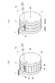
X線焦点2は、例えば図2(a)に示すように、陰極であるフィラメント7から放射された電子束が対陰極であるロータターゲット8の外周表面に衝突する領域として形成されている。ロータターゲット8は、X線焦点2の領域での損傷を防止するために、図示しない駆動装置によって駆動されて、自身の中心線X0を中心として矢印Aのように回転する。このため、電子がターゲット8の表面を走査する方向は、矢印Bで示すように、ターゲット8の回転方向と反対の方向である。
For example, as shown in FIG. 2A, the X-ray
X線焦点2に電子が衝突したとき、そのX線焦点2からX線が放射される。そして、ロータターゲット8を包囲している隔壁(図示せず)に設けたX線窓11からX線R1が外部へ取り出される。このX線R1が試料3(図1参照)に照射される。本実施形態では、X線R1は、X線焦点2から放射されるX線をX線焦点2の短手側から取り出したX線であり、その断面形状が円形又は矩形のドット状である、いわゆるポイントフォーカスのX線ビームである。
When electrons collide with the X-ray
ロータターゲット8の外周面には、原子番号が互いに異なる複数種類(本実施形態では2種類)の金属である第1の金属9a及び第2の金属9bが設けられている。第1の金属9aは、例えばCu(銅)であり、第2の金属9bは、例えばMo(モリブデン)である。金属9a及び9bのそれぞれは、フィラメント7からの電子がターゲット8の外周表面を走査する方向(矢印Bで示す方向)に沿って連続して、すなわちリング状又は環状に、設けられている。さらに、金属9a及び9bは、電子がターゲット8の外周表面を走査する方向と直角方向(図2(a)の上下方向)に互いに隣接して設けられている。
The outer surface of the
第1の金属9aに電子が衝突したとき、特性線であるCuKα線(波長1.542Å)を含むX線が放射される。他方、第2の金属9bに電子が衝突したとき、特性線であるMoKα線(波長0.711Å)を含むX線が放射される。つまり、本実施形態では、ロータターゲット8から出射されるX線R1に、互いに違ったターゲット素材の特性X線であるCuKα線及びMoKα線が混在して含まれている。
When electrons collide with the
なお、測定対象である試料の種類や、X線測定の条件に従って、ポイントフォーカスのX線ビームを取り出すことに替えて、図3(a)に示すようにラインフォーカスのX線ビームを取り出す場合もある。ラインフォーカスのX線ビームとは、X線焦点2から放射されるX線をX線焦点2の長手側から取り出したX線であり、その断面形状が1つの方向に長い長方形状であるようなX線ビームである。
Note that a line-focused X-ray beam may be extracted as shown in FIG. 3A instead of extracting a point-focused X-ray beam according to the type of sample to be measured and the X-ray measurement conditions. is there. The line focus X-ray beam is an X-ray obtained by extracting X-rays radiated from the X-ray
図1に戻って、試料支持装置4は、可動部を持たない単なる支持台や、3軸ゴニオメータや、4軸ゴニオメータ等によって構成される。3軸ゴニオメータは、3つの回転軸のそれぞれの周りに回転可能な回転系を含んでいるゴニオメータ(すなわち測角器)である。4軸ゴニオメータは、4つの回転軸のそれぞれの周りに回転可能な回転系を含んでいる測角器である。いずれの構成の試料支持装置を利用するかは、試料3の特性及び測定の種類に応じて決められる。
Returning to FIG. 1, the
試料3は分子の構造を解析したい任意の物質であり、例えば単結晶物質、タンパク質物質、創製に係る医薬品、等である。試料3の支持の仕方は、試料3の特性に応じて適宜に選定される。例えば、単結晶物質のような固体試料の場合は支持棒の先端に接着することができ、流動状試料の場合はキャピラリチューブに収納することができ、粉末試料の場合は試料ホルダの凹部又は貫通孔に詰め込むことができる。タンパク質単結晶の場合は所定の収納容器に収納することができる。図1では試料3の形状を球状に描いているが、実際には、試料の種類に応じて適宜の形状の試料が測定に供される。
The
X線検出器6は、本実施形態では、いわゆるパルス計数型ピクセルアレイ2次元検出器を用いている。このX線検出器6は、X線検出手段としての平面状X線検出部13と、X線検出部13と略同じ面積である信号処理回路板14とを有している。平面状X線検出部13は、複数のX線受光用ピクセル12を2次元的にアレイ化することによって形成されている。図1では、分かり易くするために個々のピクセル12を実際よりも大きく描いている。なお、複数のピクセル12は、規則的な配列であればその形態は自由である。
In this embodiment, the X-ray detector 6 uses a so-called pulse counting pixel array two-dimensional detector. The X-ray detector 6 includes a
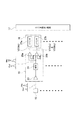
信号処理回路板14は、X線検出部13の背面(すなわち、受光面の裏面)にそのX線検出部13に接触又は近接して設けられている。信号処理回路板14上には、図4に示すように、複数のX線受光用ピクセル12の個々に接続された分別回路15と、分別回路15の個々に接続されたカウンタ部16と、各カウンタ部16に接続されたカウンタ読出し回路17と、入出力インターフェース18と、が設けられている。図4では、複数のピクセル12が1次元的なライン状に描かれているが、実際には図1に示すマトリクス状の複数のピクセル12の個々に分別回路15及びカウンタ部16が接続されている。
The signal
分別回路15は、ピクセル12のパルス信号をX線波長ごとに分別して出力する回路である。カウンタ部16は、分別回路15によって波長毎に分別された信号のそれぞれの個数を計数する回路である。カウンタ部16は、例えば、分別回路15によって分別された数のパルス信号と同じ数のカウンタ回路を内蔵する。なお、分別回路15及びカウンタ部16のブロックによる分別はデータとして取込んだ後にソフトウエアで行うことも可能である。
The
カウンタ読出し回路17の出力信号はインターフェース18を介して、外部のコンピュータ19、例えば机上に設置されたパーソナルコンピュータに通信線を通して伝送される。あるいは、カウンタ読出し回路17の出力信号を、さらに別のインターフェース回路20を通じて読み出すことにし、このインターフェース回路20により並べ替えや補正等といったデータ加工を行うこともできる。コンピュータ19は周知の演算処理手段であり、例えば、演算制御手段であるCPU(Central Processing Unit)、記憶手段であるメモリ、メモリ内の所定領域に記憶されたシステムソフト、及びメモリ内の他の所定領域に記憶されたアプリケーションプログラムソフト、等によって構成されている。
An output signal of the
コンピュータ19の出力ポートには、液晶表示装置等といったディスプレイ21と、静電転写印字装置等といったプリンタ22とが接続されている。ディスプレイ21及びプリンタ22は、必要に応じて、コンピュータ19からの指示に従って測定結果を、それぞれ、画面上又は紙等の上に表示する。
The output port of the
複数のピクセル12のそれぞれは、主としてシリコン等といった半導体によって形成されており、X線を受け取ったときにそのX線の波長(エネルギ)に応じて生成した電荷をX線光子数の積算としてパルス信号を出力する。例えば、CuKα線のX線光子を受けたときに波高V1のピーク波形を出力し、MoKα線のX線光子を受けたときに波高V2のピーク波形を出力する。X線光子のエネルギはCuKα<MoKαなので、V1<V2となる。
Each of the plurality of
分別回路15は、波長毎(すなわちエネルギ毎)に異なった状態(実施形態では異なった波高値)で出力される各ピクセル12の出力信号を、波長毎に分別して出力する回路である。この分別回路15は、例えば図5に示すように、信号増幅用のアンプ23と、ピーク波形をカウンタに適したピーク波形に成形する波形成形回路24と、2つのコンパレータ26a,26bとを有している。各コンパレータ26a及び26bの基準参照電圧端子には、それぞれ、電圧Va及びVbが印加されている。
The
V1<Va<V2であり、Vb<V1である。従って、コンパレータ26aは、Vaよりも大きい波高V2の出力信号(MoKα線)を出力する。一方、コンパレータ26bは、Vbよりも大きい波高V1(CuKα線)及びV2(MoKα線)の両方を出力する。
V1 <Va <V2 and Vb <V1. Therefore, the
図4のカウンタ部16は、図5に示すように、コンパレータ26a及び26bの個々の出力端子に接続されたカウンタ27a及び27bを有している。各カウンタ27a,27bは、コンパレータ26a,26bの出力端子に信号が出力されるたびに、その出力信号をカウントし、所定時間内のカウント数を出力信号として出力する。カウンタ27aは波高V2のカウント数を出力し、カウンタ27bは波高V1のカウント数と波高V2のカウント数とを足し算したカウント数を出力する。
As shown in FIG. 5, the
カウンタ読出し回路17は、カウンタ27aのカウント数から波高V2のカウント数を決定し、カウンタ27bのカウント数(V1数+V2数)からカウンタ27aのカウント数(V2数)を引き算した値から波高V1のカウント数を演算する。そして、カウンタ読出し回路17は、行列番地(i,j)のピクセル12において波高V1(CuKα線)が何パルスだけカウントされたか、及び波高V2(MoKα線)が何パルスだけカウントされたかを出力する。この出力信号は、図4において、コンピュータ19へ伝送される。
The
コンピュータ19は、図1に示す平面状のX線検出部13が検出した回折線の平面内での位置と、カウンタ読出し回路17が演算した回折線の波長毎の強度カウント値とに基づいて、回折線の波長と、回折角度と、強度との関係を演算する。すなわち、コンピュータ19は、特定の波長のX線が何度の回折角度で何カウントの強度で回折したか、を演算する。これにより、回折角度と回折強度との関係を表す回折線図形すなわち回折線プロファイルを回折線の波長別に取得でき、さらに画面等に表示できる。
The
本実施形態に係る波長分別型X線回折装置1は以上のように構成されているので、図1において、X線源であるX線焦点2からCuKα線及びMoKα線を含むポイントフォーカスのX線R1(図2(a)参照)、場合によっては必要に応じてラインフォーカスのX線R1(図3(a)参照)が放射され、そのX線が試料3へ入射する。試料3がCuKα線に適合した結晶格子面を有していればCuKα線の回折X線R2が試料3から出射し、試料3がMoKα線に適合した結晶格子面を有していればMoKα線の回折X線R3が試料3から出射する。
Since the wavelength-fractionated X-ray diffractometer 1 according to the present embodiment is configured as described above, in FIG. 1, the point focus X-ray including the CuKα ray and the MoKα ray from the X-ray
CuKα線の回折X線R2とMoKα線の回折X線R3とは、同時に(すなわち試料3への1回のX線照射時に)2次元X線検出部13の受光面の全領域内に受光される。このとき、図4の分別回路15によって回折X線R2の像と回折X線R3の像とが複数のピクセル12の個々において分別され、分別されたそれらの像がカウンタ部16によって、個々のピクセル12毎で波長毎にカウントされる。
The diffracted X-ray R2 of CuKα ray and the diffracted X-ray R3 of MoKα ray are received simultaneously in the entire region of the light receiving surface of the two-dimensional X-ray detector 13 (that is, when the
そして、カウンタ読出し回路17によって波長毎の回折X線強度がカウント数として求められ、その結果が電気信号の形でコンピュータ19へ伝送される。コンピュータ19は、内蔵しているプログラムソフトによる制御に従って、ピクセル12の番地(i,j)に関連付けて波長毎の回折X線強度を決定し、その結果のデータをコンピュータ19内のメモリ内の所定領域に記憶する。
The
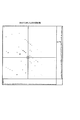
メモリ内に記憶された回折X線R2の像(Cu像)と回折X線R3の像(Mo像)との両方の回折像のデータを、所定の画像表示プログラムに従ってディスプレイ21又はプリンタ22によって表示すれば、例えば図6に示すように、回折X線R2の像(Cu像)と回折X線R3の像(Mo像)との両方が広く混在して分布している2次元回折像が表示される。
The diffraction image data of both the diffraction X-ray R2 image (Cu image) and the diffraction X-ray R3 image (Mo image) stored in the memory are displayed on the
他方、メモリ内に記憶された回折X線R2の像(Cu像)と回折X線R3の像(Mo像)との両方の回折像のデータから、所定の波長選択プログラムに従って、回折X線R2の像(Cu像)を選択し、この選択されたデータをディスプレイ21等に表示すれば、図7に示すように、回折X線R2の像(Cu像)だけを選択的に表示させて観察することができる。
On the other hand, from the diffraction image data of both the diffraction X-ray R2 image (Cu image) and the diffraction X-ray R3 image (Mo image) stored in the memory, according to a predetermined wavelength selection program, the diffraction X-ray R2 If the selected image (Cu image) is selected and the selected data is displayed on the
他方、メモリ内に記憶された回折X線R2の像(Cu像)と回折X線R3の像(Mo像)との両方の回折像のデータから、所定の波長選択プログラムに従って、回折X線R3の像(Mo像)を選択し、この選択されたデータをディスプレイ21等に表示すれば、図8に示すように、回折X線R3の像(Mo像)だけを選択的に表示させて観察することができる。
On the other hand, from the diffraction image data of both the diffraction X-ray R2 image (Cu image) and the diffraction X-ray R3 image (Mo image) stored in the memory, according to a predetermined wavelength selection program, the diffraction X-ray R3 If the selected image (Mo image) is selected and the selected data is displayed on the
以上のように、本実施形態の波長分別型X線回折装置1によれば、異なる波長の回折線(CuKα線、MoKα線)を含む回折線ビームを、ピクセル12毎に波長分別機能を持たせたピクセルアレイ検出器6によって検出することにしたので、回折線を波長毎に検出できる。そのため、異なる波長のX線に基づいた測定データを1回の測定によって同時に取得できる。これにより、図2(a)に示すX線発生部におけるエネルギの浪費を防止でき、ターゲット8の短期間での消耗を防止でき、異なった波長のX線のそれぞれに基づく測定データを短時間に取得できる。測定が短時間で完了するので、試料3(図1)が結晶構造を長時間維持できない物質である場合でも問題なく測定を行うことができる。
As described above, according to the wavelength classification X-ray diffractometer 1 of the present embodiment, each
従来のX線回折装置において、X線検出器を構成する平面状のX線検出部をパルス計数型のピクセルアレイ検出器ではなく、電荷積分型のCCD検出器によって形成し、そのX線検出部の受光面を上下半分等のように区分けして、区分けしたそれぞれの領域で異なる波長の回折線を受光するようにしたものがあった。この構成では各波長分の検出領域が狭くなってデータの信頼性が低下するおそれがあった。これに対し、本実施形態のX線回折装置では、異なる波長の回折線のそれぞれをX線検出器6のX線検出部13の受光面の全領域で受光することにしたので、異なる波長の複数の回折線のデータのそれぞれを広い範囲にわたって取得することができ、その結果、信頼性の高い回折線データを得られるようになった。
In a conventional X-ray diffractometer, a planar X-ray detection unit constituting an X-ray detector is formed by a charge integration type CCD detector instead of a pulse counting type pixel array detector, and the X-ray detection unit The light receiving surface is divided into upper and lower halves, etc., and diffracted rays having different wavelengths are received in the divided regions. In this configuration, the detection area for each wavelength is narrowed, and the reliability of the data may be reduced. On the other hand, in the X-ray diffractometer of the present embodiment, each of the diffraction lines having different wavelengths is received by the entire region of the light receiving surface of the
(第2の実施形態)
本実施形態では、第1の実施形態に対して、X線発生部に改変を加えるものとする。
上記第1の実施形態では、図2(a)及び図3(a)に示したように、第1の金属9a及び第2の金属9bのそれぞれを、フィラメント7からの電子がターゲット8の外周表面を走査する方向(矢印Bで示す方向)に沿って連続して、すなわちリング状又は環状に設けた。さらに、電子がターゲット8の外周表面を走査する方向と直角方向(図2(a)の回転軸線X0と平行方向)に沿って、第1の金属9aと第2の金属9bとを互いに隣接して設けた。
(Second Embodiment)
In the present embodiment, the X-ray generation unit is modified with respect to the first embodiment.
In the first embodiment, as shown in FIG. 2A and FIG. 3A, each of the
これに対し、本実施形態では、図2(b)及び図3(b)に示すように、フィラメント7からの電子がターゲット28の外周表面を走査する方向(矢印Bで示す方向)に沿って第1の金属9a及び第2の金属9bを所定幅で交互に設けている。この構成は、金属9aと金属9bとが縞状、ストライプ状に設けられていることから、ストライプターゲットと呼ばれている。また、ゼブラ型ターゲットと呼ばれることがある。なお、図2(b)はポイントフォーカスのX線ビームを取り出すための構成であり、図3(b)はラインフォーカスのX線ビームを取り出すための構成である。
On the other hand, in this embodiment, as shown in FIGS. 2B and 3B, the electrons from the
本実施形態においても、フィラメント7からの電子の放出、及びターゲット28の中心線X0を中心とした回転により、X線焦点2から出射するX線R1の中に、異なる波長のX線を含ませることができる。つまり、本実施形態では、ロータターゲット28から出射されるX線R1に、互いに違ったターゲット素材の特性X線であるCuKα線及びMoKα線が混在して含まれている。
Also in this embodiment, X-rays having different wavelengths are included in the X-ray R1 emitted from the X-ray
(変形例)
図2(a),(b)及び図3(a),(b)に示した第1の金属9aはCuに限られない。また、第2の金属9bはMoに限られない。従って、図1に示したX線R1,R2,R3はCu線、Mo線に限られない。また、図5では2つのコンパレータ26a,26bと、カウンタ27a,27bと、カウンタ読出し回路17とによって、波高V1で示された波長及び波高V2で示された波長の2つの波長を引き算を利用して分別した。しかしながら、これに代えて、基準参照電圧すなわち閾値を3つ以上設定することにより、引き算の演算をすることなく、波高V1で示された波長と波高V2で示された波長とを直接に分別しても良い。
(Modification)
The
さらに、上記実施形態では図2(a),(b)及び図3(a),(b)においてターゲット8,28に2種類の金属9a,9bを設けたが、これに代えて、ターゲットの表面に3種類以上の金属を設けて、3種類以上の波長のX線を発生させるようにしても良い。この場合には、図5のコンパレータ26a,26b及びカウンタ27a,27bの数を必要に応じて増加する。
Further, in the above embodiment, two types of
(第3の実施形態)
図9は本発明に係る波長分別型X線回折装置の他の実施形態を示している。本実施形態でも、第1の実施形態に対して、X線発生部に改変を加えるものとする。上記第1の実施形態では、図1に示したように、1つのX線源すなわちX線焦点2から波長の異なった複数の特性X線を含むX線R1を出射することにした。
(Third embodiment)
FIG. 9 shows another embodiment of the wavelength classification type X-ray diffractometer according to the present invention. Also in this embodiment, the X-ray generation unit is modified with respect to the first embodiment. In the first embodiment, as shown in FIG. 1, the X-ray R1 including a plurality of characteristic X-rays having different wavelengths is emitted from one X-ray source, that is, the X-ray
これに対し、図9に示す本実施形態では、第1X線発生部としての第1のX線源2aから放射されたX線R1aと、第2X線発生部としての第2のX線源2bから放射されたX線R1bとを試料3へ同時に照射している。X線R1a及びX線R1bは、いずれも、単一波長のX線である。この実施形態では、X線R1a及びX線R1bの試料3に対する入射角度が異なっている。その他の構成は図1に示したX線回折装置1と同じである。ここで、図9に示したX線R1a,R1b,R2,R3は、Cu線やMo線に限られない。
On the other hand, in the present embodiment shown in FIG. 9, the X-ray R1a emitted from the
(第4の実施形態)
以下、重原子を含む低分子試料の構造解析に本発明を適用した場合の実施形態を説明する。本実施形態の波長分別型X線回折装置の全体的な構成は、図1又は図9に示した構成とすることができる。図1の場合は、X線焦点2から、互いに違ったターゲット素材の特性X線であるCuKα線及びMoKα線が同時に出射されて試料3に供給される。試料に供給されるX線としては、例えばポイントフォーカス(図2(a),(b)参照)が用いられる。
(Fourth embodiment)
Hereinafter, an embodiment in which the present invention is applied to the structural analysis of a low-molecular sample containing heavy atoms will be described. The overall configuration of the wavelength classification X-ray diffraction apparatus of the present embodiment can be the configuration shown in FIG. 1 or FIG. In the case of FIG. 1, CuKα rays and MoKα rays, which are characteristic X rays of different target materials, are simultaneously emitted from the X-ray
上記の重原子は、例えばFe、Co、Mo、Wである。一方、軽原子は、例えばC、H、N、O、Sである。一般に、CuKα線(波長1.542Å)は重原子に吸収され易く、MoKα線(波長0.711Å)は重原子に吸収され難い。従って、重原子を含む低分子試料の構造解析はMoKα線を使って行うことが多い。 The above heavy atoms are, for example, Fe, Co, Mo, W. On the other hand, light atoms are C, H, N, O, and S, for example. In general, CuKα rays (wavelength 1.542Å) are easily absorbed by heavy atoms, and MoKα rays (wavelength 0.711Å) are hardly absorbed by heavy atoms. Therefore, structural analysis of low molecular weight samples containing heavy atoms is often performed using MoKα rays.
しかしながら、CuKα線はX線効率が高いので、小さい結晶に高強度のX線を供給できる。また、格子長が長いサンプルは点状の回折像同士の間隔が蜜になる一方、Cu線は波長が長いので回折像同士の間隔が広くなる。従って、結晶サイズが小さかったり、格子長が長い場合には、重原子を含んでいてもCu線の使用を希望することがある。 However, since CuKα rays have high X-ray efficiency, high-intensity X-rays can be supplied to small crystals. In addition, the sample having a long grating length has a narrow interval between the dotted diffraction images, whereas the Cu line has a long wavelength, so that the interval between the diffraction images becomes wide. Therefore, when the crystal size is small or the lattice length is long, it may be desired to use Cu wire even if it contains heavy atoms.
従って、格子長が長く、重原子を含み、小さい結晶である試料は、Cu線で初期構造を決定し、Mo線で構造の精密化を行いたいという要望がある。本実施形態の波長分別型X線回折装置はこの要望に応えることができる。本実施形態の波長分別型X線回折装置によれば、Cu線によるデータとMo線によるデータとを1つのプロセス(すなわち、試料に対する1回のX線照射時)において同時に取得することができる。 Therefore, there is a demand for a sample having a long lattice length, containing heavy atoms, and being a small crystal to determine the initial structure with Cu wire and to refine the structure with Mo wire. The wavelength separation type X-ray diffraction apparatus of this embodiment can meet this demand. According to the wavelength classification type X-ray diffractometer of this embodiment, Cu line data and Mo line data can be simultaneously acquired in one process (that is, at the time of one X-ray irradiation on a sample).
2次元ピクセルアレイ検出器の平面サイズは、例えば60mm×80mm〜120mm×160mmである。ピクセルアレイ検出器を形成している個々のピクセルのサイズ及び数については、特別の限定は無い。しかしながら、ピクセルサイズは、少なくとも0.1°の分解能を達成できるサイズであることが望ましい。ピクセル数は検出器の平面サイズとピクセルサイズとが決まれば、自動的に決まる。 The planar size of the two-dimensional pixel array detector is, for example, 60 mm × 80 mm to 120 mm × 160 mm. There is no particular limitation on the size and number of individual pixels forming the pixel array detector. However, it is desirable that the pixel size is a size that can achieve a resolution of at least 0.1 ° . The number of pixels is automatically determined once the planar size and pixel size of the detector are determined.
(第5の実施形態)
結晶構造解析の分野において光学異性体(すなわちキラリティ)が知られている。本実施形態の波長分別型X線回折装置は、光学活性を有する物質の構造解析に用いられるものである。本実施形態の波長分別型X線回折装置の全体的な構成は図1又は図9に示した構成とすることができる。図1の場合は、X線焦点2から、互いに違ったターゲット素材の特性X線であるCu線及びMo線が同時に出射されて試料3に供給される。試料に供給されるX線としては、例えばポイントフォーカス(図2(a),(b)参照)が用いられる。
(Fifth embodiment)
Optical isomers (ie, chirality) are known in the field of crystal structure analysis. The wavelength-fractionated X-ray diffractometer of this embodiment is used for structural analysis of a substance having optical activity. The overall configuration of the wavelength classification X-ray diffractometer of the present embodiment can be the configuration shown in FIG. 1 or FIG. In the case of FIG. 1, Cu rays and Mo rays, which are characteristic X rays of different target materials, are simultaneously emitted from the X-ray
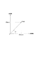
光学異性体とは、図10に模式的に示すように、同じ化学構造式にも関わらず、立体的な構造の違いから異なる挙動を示す物質である。例えば、図10(a)のR体が医薬として有用であり、図10(b)のS体は毒性を示すことがある。一般に、2つの光学異性体の回折線は、ほぼ等しいが、異常分散項についてわずかに差が生じ、両者間で回折線強度にわずかの違いが出る。 As schematically shown in FIG. 10, optical isomers are substances that exhibit different behaviors due to differences in steric structure, despite the same chemical structural formula. For example, the R form of FIG. 10 (a) is useful as a medicine, and the S form of FIG. 10 (b) may be toxic. In general, the diffraction lines of the two optical isomers are approximately equal, but there is a slight difference in the anomalous dispersion term, and there is a slight difference in diffraction line intensity between the two.
このわずかな差を検出してどちらの構造なのかを求める際、すなわち絶対構造を求める際、の指標となるのがフラックパラメータ(Flack Parameter)である。 When a slight difference is detected to determine which structure is obtained, that is, when an absolute structure is obtained, a Flack Parameter is an index.
しかしながら、C(炭素)、H(水素)、N(窒素)、0(酸素)等の軽原子のみから構成される有機化合物の場合は、特に波長の長いX線を用いないとそのわずかな違いを検出することができず、フラックパラメータを用いた構造決定が困難になる。従って、光学異性体の構造解析においては、CuKα線でフラックパラメータを求め、MoKα線で構造の精密化を行いたいという要望がある。本実施形態の波長分別型X線回折装置はこの要望に応えることができる。 However, in the case of organic compounds composed only of light atoms such as C (carbon), H (hydrogen), N (nitrogen), and 0 (oxygen), there is a slight difference unless X-rays having a long wavelength are used. Cannot be detected, and the structure determination using the flack parameter becomes difficult. Therefore, in the structural analysis of optical isomers, there is a demand to obtain a flack parameter with CuKα rays and refine the structure with MoKα rays. The wavelength separation type X-ray diffraction apparatus of this embodiment can meet this demand.
本実施形態の波長分別型X線回折装置によれば、CuKα線によるデータとMoKα線によるデータとを1つのプロセス(すなわち、試料に対する1回のX線照射時)において同時に取得することができる。 According to the wavelength classification type X-ray diffractometer of this embodiment, it is possible to simultaneously acquire CuKα ray data and MoKα ray data in one process (that is, at the time of one X-ray irradiation on a sample).
(第6の実施形態)
以下、タンパク質結晶の構造解析に本発明を適用した場合の実施形態を説明する。本実施形態の波長分別型X線回折装置の全体的な構成は、図1又は図9に示した構成とすることができる。図1の場合は、X線焦点2から、互いに違ったターゲット素材に基づいた複数の特性X線が同時に出射されて試料3に供給される。試料に供給されるX線としては、例えばポイントフォーカス(図2(a),(b)参照)が用いられる。
(Sixth embodiment)
Hereinafter, an embodiment when the present invention is applied to the structural analysis of protein crystals will be described. The overall configuration of the wavelength classification X-ray diffraction apparatus of the present embodiment can be the configuration shown in FIG. 1 or FIG. In the case of FIG. 1, a plurality of characteristic X-rays based on different target materials are simultaneously emitted from the X-ray
周知の通り、タンパク質はC(炭素)、N(窒素)等といった軽原子によって形成されたアミノ酸物質である。X線を用いた結晶構造解析は、タンパク質の立体構造を原子レベルで決定できる好適な手法である。具体的には、タンパク質結晶から出る散乱線の強度分布から計算によって原子の位置を決定するものである。より具体的には、タンパク質のX線構造解析は、結晶構造因子F(hkl)をフーリエ合成して電子密度ρ(xyz)を求めることである。 As is well known, proteins are amino acid substances formed by light atoms such as C (carbon) and N (nitrogen). Crystal structure analysis using X-rays is a suitable technique that can determine the three-dimensional structure of a protein at the atomic level. Specifically, the position of the atom is determined by calculation from the intensity distribution of scattered radiation emitted from the protein crystal. More specifically, the X-ray structural analysis of protein is to obtain the electron density ρ (xyz) by Fourier synthesis of the crystal structure factor F (hkl).
結晶構造因子F(hkl)は、図11に示すように複素量であり、|F(hkl)|(絶対値)と位相角αが分からないと複素量であるF(hkl)は規定できない。結晶構造因子の絶対値|F(hkl)|は回折線強度I(hkl)(=|F(hkl)|2)の測定で得られる。位相角αは実験的には求められない。位相角αの決定法として従来からいくつかの手法が知られている。その中の1つとして多波長異常分散法(MAD法/Multi-Wavelength Anomalous Dispersion Method法)が知られている。また、近年では、単波長異常散乱法(SAD法/Single-Wavelength Anomalous Dispersion Method法)が利用されるようになってきた。 The crystal structure factor F (hkl) is a complex quantity as shown in FIG. 11, and F (hkl) which is a complex quantity cannot be defined unless | F (hkl) | (absolute value) and the phase angle α are known. The absolute value | F (hkl) | of the crystal structure factor can be obtained by measuring the diffraction line intensity I (hkl) (= | F (hkl) | 2 ). The phase angle α cannot be obtained experimentally. Conventionally, several methods are known for determining the phase angle α. As one of them, a multi-wavelength anomalous dispersion method (MAD method / Multi-Wavelength Anomalous Dispersion Method method) is known. In recent years, single-wavelength anomalous scattering method (SAD method / Single-Wavelength Anomalous Dispersion Method method) has come to be used.
MAD法は、タンパク質中に含まれる特定原子の吸収端近傍での異常分散効果を利用して位相決定を行うものである。具体的には、特定原子の吸収端を挟んだ少なくとも3種類の波長のX線を使って回折線強度を測定する。SAD法は、ある1つの波長で測定した異常散乱強度のみで位相決定を行うものである。 The MAD method performs phase determination using an anomalous dispersion effect near the absorption edge of a specific atom contained in a protein. Specifically, the diffraction line intensity is measured using X-rays of at least three types of wavelengths sandwiching the absorption edge of a specific atom. In the SAD method, the phase is determined only by the extraordinary scattering intensity measured at a certain wavelength.
本実施形態では、結晶構造因子F(hkl)の位相角αをMAD法によって求める場合、CuKα(波長1.542Å)、CoKα(波長1.789Å)、CrKα(波長2.290Å)、MoKα(0.711Å)から3種類のX線を用い、各X線に基づいた回折角度及び回折線強度を測定するものとする。この場合には、X線発生装置を構成するロータターゲットの表面にCu、Co、Cr及びMoの各金属を設けることによって電子受光面(すなわち、X線出射面)を形成する。 In the present embodiment, when the phase angle α of the crystal structure factor F (hkl) is obtained by the MAD method, Cu Kα (wavelength 1.542Å), Co Kα (wavelength 1.789Å), Cr Kα (wavelength 2.290Å) , Three types of X-rays are used from MoKα (0.711 Å), and the diffraction angle and diffraction line intensity based on each X-ray are measured. In this case, an electron receiving surface (that is, an X-ray emission surface) is formed by providing Cu, Co, Cr, and Mo metals on the surface of the rotor target that constitutes the X-ray generator.
また、本実施形態においてSAD法を実施する場合には、CoKα線又はCrKα線を用いて位相角を決定し、CuKα線を用いて回折線強度の測定を精密に行う。CrKα線及びCoKα線は試料での吸収が大きいので、位相角の決定に適している。CuKα線の回折線は強度が強く、吸収が小さいので、良質な回折データを得ることができ、精密な分析を行うことができる。 Further, when the SAD method is performed in the present embodiment, the phase angle is determined using the CoKα line or the Cr Kα line , and the diffraction line intensity is accurately measured using the Cu Kα line . Since Cr Kα ray and CoKα ray have a large absorption in the sample, they are suitable for determining the phase angle. Since the diffraction line of Cu Kα ray has high intensity and low absorption, good diffraction data can be obtained and precise analysis can be performed.
なお、タンパク質は格子長が長い物質である。具体的には、格子長は100〜500Åである。格子長が長いと、得られる点状の回折像が狭い間隔単位(すなわち、狭い回折角度単位)で表現されることになり、観察し難くなる。この場合、Mo線よりも波長の長いCu線を用いれば、回折像の表示間隔単位が広くなるので、回折プロファイルの観察を容易に行うことが可能となる。 Protein is a substance having a long lattice length. Specifically, the lattice length is 100 to 500 mm. When the grating length is long, the obtained point-like diffraction image is expressed in a narrow interval unit (that is, a narrow diffraction angle unit), which makes it difficult to observe. In this case, if a Cu line having a wavelength longer than that of the Mo line is used, the display interval unit of the diffraction image becomes wide, so that the diffraction profile can be easily observed.
本実施形態によれば、MAD法の場合でも、SAD法の場合でも、複数種類の波長のX線が1つのタンパク質試料に照射され、それらの波長に対応した回折線が2次元ピクセルアレイ検出器に同時に受け取られる。そして、波長別に(すなわちエネルギ別に)回折角度及び回折線強度が測定される。 According to this embodiment, in the case of both the MAD method and the SAD method, X-rays of a plurality of types of wavelengths are irradiated to one protein sample, and the diffraction lines corresponding to these wavelengths are two-dimensional pixel array detectors. Received at the same time. Then, the diffraction angle and the diffraction line intensity are measured for each wavelength (that is, for each energy).
2次元ピクセルアレイ検出器の平面サイズは、例えば80mm×120mm〜240mm×240mmである。ピクセルアレイ検出器を形成している個々のピクセルのサイズ及び数については、特別の限定は無い。しかしながら、ピクセルサイズは、少なくとも0.1°の分解能を達成できるサイズであることが望ましい。ピクセル数は検出器の平面サイズとピクセルサイズとが決まれば、自動的に決まる。 The planar size of the two-dimensional pixel array detector is, for example, 80 mm × 120 mm to 240 mm × 240 mm. There is no particular limitation on the size and number of individual pixels forming the pixel array detector. However, it is desirable that the pixel size is a size that can achieve a resolution of at least 0.1 ° . The number of pixels is automatically determined once the planar size and pixel size of the detector are determined.
(第7の実施形態)
以下、粉末試料の構造解析に本発明を適用した場合の実施形態を説明する。本実施形態の波長分別型X線回折装置の全体的な構成は、図1又は図9に示した構成とすることができる。図1の場合は、X線焦点2から、互いに違ったターゲット素材に基づいた複数の特性X線が同時に出射されて試料3に照射される。試料に照射されるX線としては、例えばラインフォーカス(図3(a),(b)参照)が用いられる。
(Seventh embodiment)
Hereinafter, an embodiment when the present invention is applied to the structural analysis of a powder sample will be described. The overall configuration of the wavelength classification X-ray diffraction apparatus of the present embodiment can be the configuration shown in FIG. 1 or FIG. In the case of FIG. 1, a plurality of characteristic X-rays based on different target materials are simultaneously emitted from the X-ray
粉末試料の分析においては、一般に図12(a)に示すように、2次元的な回折像I1,I2,I3,…が測定によって求められ、各回折像が個々に積分されて、回折角度2θの個々の角度における回折線強度とされる。そして、赤道線Eに対応した線を横軸とした図12(b)の回折図形座標上に回折プロファイルとして表示される。 In the analysis of a powder sample, generally, as shown in FIG. 12A, two-dimensional diffraction images I 1 , I 2 , I 3 ,... Are obtained by measurement, and each diffraction image is individually integrated, The diffraction line intensity at each angle of the diffraction angle 2θ is used. And it displays as a diffraction profile on the diffraction pattern coordinate of FIG.12 (b) which made the line corresponding to the equator line E a horizontal axis.
測定に使用されるX線の波長が短いと回折角度が小さくなるため、回折図形の横軸上での回折像(いわゆる回折線)の表示間隔が狭く表示される。一方、測定に使用されるX線の波長が長いと回折角度が大きくなるため、回折図形の横軸上での回折像(いわゆる回折線)の表示間隔が広く表示される。 When the wavelength of X-rays used for measurement is short, the diffraction angle becomes small, so that the display interval of diffraction images (so-called diffraction lines) on the horizontal axis of the diffraction pattern is displayed narrowly. On the other hand, when the wavelength of X-rays used for measurement is long, the diffraction angle increases, so that the display interval of diffraction images (so-called diffraction lines) on the horizontal axis of the diffraction pattern is displayed wide.
このように、測定に使用するX線の波長が長いと、回折像(いわゆる回折線)の回折プロファイルが分析を実施するうえで容易になるので、通常の粉末測定では、波長が短いX線は特殊な目的以外に使用することは少ない。例えば、波長1.5418ÅであるCuKα線は、波長0.7107ÅであるMoKα線等に比べて波長が長く、粉末測定の際のX線として最も広く用いられている。 In this way, if the wavelength of X-rays used for measurement is long, the diffraction profile of the diffraction image (so-called diffraction lines) becomes easy to carry out the analysis, so in normal powder measurement, X-rays with short wavelengths are It is rarely used for anything other than a special purpose. For example, a CuKα ray having a wavelength of 1.5418Å has a longer wavelength than that of a MoKα ray having a wavelength of 0.7107Å, and is most widely used as an X-ray in powder measurement.
しかしながら、一般的に金属の分類に属する物質に対して、CuKα線はMoKα線に比べて特に吸収される割合が高く、それ故、CuKα線によって求められた2次元回折画像は吸収に因って発生する散乱X線の影響で明瞭性に欠けるという問題、具体的には、2次元画像上で回折像(いわゆる回折線)を明瞭に表示する特性が不十分であるという問題がある。また、透過法測定においては、重原子を含む試料の場合、吸収が大きいCuKα線では透過自体が困難であるという問題がある。また、MoKα線は波長が短いので、回折図形座標上に得られる回折像(いわゆる回折線)の回折角度方向(通常は横軸方向)の表示間隔が狭くなってしまい、例えば、鉱物や高分子など結晶構造が大きな試料の場合、回折像(いわゆる回折線)が重なってしまい、各回折像(いわゆる回折線)を表現する格子面インデックス(hkl)を決めることが困難になるという問題が発生する。 However, in general, CuKα rays have a higher rate of absorption compared to MoKα rays for substances belonging to the metal classification, and therefore the two-dimensional diffraction image obtained by CuKα rays is due to absorption. There is a problem of lack of clarity due to the influence of the scattered X-rays generated. Specifically, there is a problem that characteristics for clearly displaying a diffraction image (so-called diffraction lines) on a two-dimensional image are insufficient. In addition, in the transmission method measurement, in the case of a sample containing heavy atoms, there is a problem that transmission itself is difficult with CuKα rays having large absorption. In addition, since the wavelength of the MoKα ray is short, the display interval in the diffraction angle direction (usually the horizontal axis direction) of the diffraction image (so-called diffraction line) obtained on the diffraction pattern coordinates becomes narrow, for example, minerals and polymers In the case of a sample having a large crystal structure, such as, diffraction images (so-called diffraction lines) are overlapped, which makes it difficult to determine a lattice plane index (hkl) representing each diffraction image (so-called diffraction line). .
以上の問題に鑑み、本実施形態では、X線発生装置を構成するロータターゲットの表面に、互いに原子番号が異なっている金属であるCu及びMoの各金属を設けることによって電子受光面(すなわち、X線出射面)を形成する。そして、その電子受光面内のX線焦点、すなわちX線源からCuKα線及びMoKα線の2種類を同時に出射して、同時に粉末試料へ照射する。 In view of the above problems, in the present embodiment, by providing each of Cu and Mo, which are metals having different atomic numbers, on the surface of the rotor target constituting the X-ray generator, an electron receiving surface (that is, X-ray emission surface) is formed. Then, an X-ray focal point in the electron receiving surface, that is, two types of CuKα ray and MoKα ray are simultaneously emitted from the X-ray source and simultaneously irradiated onto the powder sample.
そして、CuKα線によって得られた回折プロファイルに基づいて格子面インデックス(hkl)から結晶系、格子定数を決定する。そして、同時に、MoKα線によって得られた回折像に基づいて結晶構造の精密化を行う。具体的には、単位格子当りの原子の数や原子の配置を明確に特定する。 Then, the crystal system and the lattice constant are determined from the lattice plane index (hkl) based on the diffraction profile obtained by the CuKα ray. At the same time, the crystal structure is refined based on the diffraction image obtained by the MoKα ray. Specifically, the number of atoms and the arrangement of atoms per unit cell are clearly specified.
上記の通り粉末試料の場合は、2次元データを赤道線上の1次元データに変換しているので、検出器は、そもそも2次元(平面)ではなくて1次元(直線)であれば良い、と考えられる。確かにそのようにも言えるが、しかしながら、2次元ピクセルアレイ検出器を用いれば、1次元ピクセルアレイ検出器の場合に比べて、粉末試料に配向がある場合にその配向によって生じる回折強度の不均一性の影響を緩和できるという利点がある。 In the case of a powder sample as described above, since the two-dimensional data is converted into one-dimensional data on the equator line, the detector may be one-dimensional (straight) instead of two-dimensional (planar) in the first place. Conceivable. Certainly, however, the use of a two-dimensional pixel array detector, when compared to a one-dimensional pixel array detector, causes a non-uniform diffraction intensity caused by the orientation of the powder sample when the orientation is present. There is an advantage that the influence of sex can be mitigated.
2次元ピクセルアレイ検出器の平面サイズは、例えば30mm×80mmである。ピクセルアレイ検出器を形成している個々のピクセルのサイズ及び数については、特別の限定は無い。しかしながら、ピクセルサイズは、望ましくは回折像(いわゆる回折線)の回折プロファイル上で0.01°の分解能を達成できるサイズである。ピクセル数は検出器の平面サイズとピクセルサイズとが決まれば、自動的に決まる。広い2θ角度範囲の測定データが欲しい場合には、検出器の平面サイズを大きくしても良いし、あるいは、小さい平面サイズの検出器をスキャンさせるという方法を採用しても良い。 The planar size of the two-dimensional pixel array detector is, for example, 30 mm × 80 mm. There is no particular limitation on the size and number of individual pixels forming the pixel array detector. However, the pixel size is preferably Ru Ah size achievable resolution 0.01 ° on the diffraction profile of a diffraction image (a so-called diffraction line). The number of pixels is automatically determined once the planar size and pixel size of the detector are determined. When measurement data in a wide 2θ angle range is desired, the plane size of the detector may be increased, or a method of scanning a detector having a small plane size may be employed.
(その他の実施形態)
以上、好ましい実施形態を挙げて本発明を説明したが、本発明はその実施形態に限定されるものでなく、請求の範囲に記載した発明の範囲内で種々に改変できる。
(Other embodiments)
The present invention has been described with reference to the preferred embodiments. However, the present invention is not limited to the embodiments, and various modifications can be made within the scope of the invention described in the claims.
例えば、図1に示した実施形態では、複数のピクセル12を2次元的、すなわち平面的に配列して成るX線検出部13の背面に接触又は近接して信号処理回路14を設けた。しかしながら、これに代えてX線検出部13と信号処理回路14とを位置的に離して設け、個々のピクセル12の個々と処理回路とを適宜の接続線によって接続させても良い。
For example, in the embodiment shown in FIG. 1, the
上記の実施形態では、ターゲットの表面の異なる位置に異種金属を貼付けの手法等によって設けたが、これに代えて、異種金属を混合して成る合金によってターゲットの表面を形成するという構成を採用することもできる。 In the above embodiment, the dissimilar metal is provided at different positions on the surface of the target by a technique such as pasting, but instead, a configuration is adopted in which the surface of the target is formed by an alloy formed by mixing dissimilar metals. You can also
上記実施形態では、図5に示したように、閾値Va及びVbを
Vb<V1(=Cu線電位)<Va<V2(=Mo線電位)
のように設定した。つまり、VaとVbとによってMo波長とCu波長とを分別した。これに代えて、次のような分別方法を採用することもできる。
In the above embodiment, the thresholds Va and Vb are set as shown in FIG.
Vb <V1 (= Cu line potential) <Va <V2 (= Mo line potential)
Was set as follows. That is, the Mo wavelength and the Cu wavelength were separated by Va and Vb. Instead of this, the following separation method may be employed.
例えば、測定のためにMoKα線及びCuKα線を使用する場合には、ターゲットを形成する異種金属としてMoとCuとが使用される。この場合、MoやCuからは、Kα線以外の特性X線、例えばKβ線、Lα線、Lβ線等も発生する。これらのKα線以外の特性X線は測定のためにはノイズとして作用する。高精度の測定を希望する場合にはKαに相当するエネルギだけを取り出すようにして、それ以外のノイズ成分は除去することが望まれる。上記の閾値Va,Vbに代えて、所望の波長の上下領域を削除できるように閾値を細かく設定すれば、X線における余分なノイズ成分を排除でき、高精度の測定を行うことができる。 For example, when MoKα and CuKα rays are used for measurement, Mo and Cu are used as different metals forming the target. In this case, characteristic X-rays other than Kα rays such as Kβ rays, Lα rays, Lβ rays, and the like are also generated from Mo and Cu. Characteristic X-rays other than these Kα rays act as noise for measurement. When high-precision measurement is desired, it is desirable to extract only the energy corresponding to Kα and remove other noise components. If the threshold value is set finely so that the upper and lower regions of the desired wavelength can be deleted instead of the threshold values Va and Vb, an excessive noise component in the X-ray can be eliminated, and highly accurate measurement can be performed.
上記の実施形態では、X線源の構成要素である対陰極をロータターゲット、すなわち回転対陰極としたが、これに代えて固定ターゲット、すなわち回転しない対陰極とすることもできる。固定ターゲットから異種の特性X線を同時に得るための技術としては、例えば、固定ターゲットを合金によって形成したり、微小な異種金属を固定ターゲットの表面に混在、例えばまだらに混在させたり、等といった技術が考えられる。 In the above embodiment, the counter cathode that is a component of the X-ray source is a rotor target, that is, a rotating counter cathode. However, instead of this, a fixed target, that is, a counter cathode that does not rotate may be used. As a technique for obtaining different types of characteristic X-rays simultaneously from a fixed target, for example, a technique such as forming a fixed target with an alloy, or mixing different kinds of metals on the surface of a fixed target, for example, mottled Can be considered.
1.波長分別型X線回折装置、 2.X線焦点(X線発生手段)、 2a.第1のX線源(第1X線発生部)、 2b.第2のX線源(第2X線発生部)、 3.試料、 4.試料支持装置、 6.X線検出器、 7.フィラメント、 8.ロータターゲット、 9a.第1の金属、 9b.第2の金属、 11.X線窓、 12.X線受光用ピクセル、 13.X線検出部(X線検出手段)、 14.信号処理回路板、 15.分別回路(分別手段)、 16.カウンタ部、 17.カウンタ読出し回路、 18.入出力インターフェース、 19.コンピュータ、 20.インターフェース、 21.ディスプレイ、 22.プリンタ、 23.信号増幅用アンプ、 24.波形成形回路、 26a,26b.コンパレータ、 27a,27b.カウンタ、 28.ロータターゲット、 31.波長分別型X線回折装置、 A.ロータターゲット回転方向、 B.電子の走査方向、 E.赤道線、 I1,I2,I3,….回折像、 R1.X線、 R2.Cu回折X線、 R3.Mo回折X線、 X0.中心線
1. 1. Wavelength separation type X-ray diffractometer, X-ray focal point (X-ray generating means), 2a. A first X-ray source (first X-ray generator), 2b. 2. a second X-ray source (second X-ray generator); Sample, 4. Sample support device, 6. 6. X-ray detector, Filament, 8. Rotor target, 9a. First metal, 9b. Second metal, 11. X-ray window, 12. 12. X-ray receiving pixel; X-ray detector (X-ray detector), 14. 15. signal processing circuit board; 15. Classification circuit (sorting means) Counter part, 17. Counter readout circuit, 18. I / O interface, 19. Computer, 20. Interface, 21. Display, 22. Printer, 23.
Claims (12)
前記X線発生手段は原子番号が異なる複数の金属によって構成され、それぞれの金属から互いに波長が異なる複数の特性X線を発生し、
前記X線検出手段は、
前記試料で回折した複数の波長の特性X線を受光して、それぞれの特性X線の波長に対応した信号を出力する複数のピクセルで構成され、
前記ピクセルのそれぞれの出力信号を特性X線の波長ごとに分別して出力する分別手段
を有することを特徴とする波長分別型X線回折装置。 A wavelength-fractionated X-ray diffractometer that irradiates a sample with characteristic X-rays generated from an X-ray generation unit and detects the characteristic X-rays diffracted by the sample with an X-ray detection unit,
The X-ray generation means is composed of a plurality of metals having different atomic numbers, and generates a plurality of characteristic X-rays having different wavelengths from each metal,
The X-ray detection means
It is composed of a plurality of pixels that receive characteristic X-rays having a plurality of wavelengths diffracted by the sample and output a signal corresponding to the wavelength of each characteristic X-ray,
Wavelength separation type X-ray diffractometer, characterized in that it comprises a separating means for separating and outputting for each wavelength of their respective output signals of the characteristic X-rays of the pixels.
電子が走査する方向に沿って異なる種類の複数の金属が交互に配置されて成るロータターゲットを有するか、
電子が走査する方向に沿って異なる種類の複数の金属のそれぞれが連続して配置され、それらの金属は電子が走査する方向と直角方向に互いに隣接して配置されて成るロータターゲットを有するか、
第1の波長のX線を発生する第1X線発生部と、第1の波長とは異なった第2の波長のX線を発生する第2X線発生部とを有し、第1X線発生部と第2X線発生部とは互いに異なった位置に配設され同じ試料にX線を照射することができるそれぞれの位置に配設されているか、
異種金属を混合して成る合金によってターゲットの表面を形成するか、又は
微小な異種金属を固定ターゲットの表面に混在させる、
ことを特徴とする請求項1から請求項5のいずれか1つに記載の波長分別型X線回折装置。 The X-ray generation means includes
A rotor target having a plurality of different types of metals arranged alternately along a direction in which electrons are scanned;
A plurality of different types of metals are sequentially arranged along the direction in which the electrons scan, and the metals have a rotor target that is arranged adjacent to each other in a direction perpendicular to the direction in which the electrons scan,
A first X-ray generator that generates an X-ray having a first wavelength; and a second X-ray generator that generates an X-ray having a second wavelength different from the first wavelength. And the second X-ray generator are arranged at different positions and can be arranged at respective positions where the same sample can be irradiated with X-rays,
The surface of the target is formed by an alloy comprising a mixture of different metals, or
Mix minute dissimilar metals on the surface of the fixed target.
The wavelength separation type X-ray diffraction apparatus according to any one of claims 1 to 5, characterized in.
複数のピクセルを2次元的に並べて成り、異なる波長の複数種類の回折線を検出できる受光面積を有した2次元ピクセルアレイ検出器であるか、又は
複数のピクセルを1次元的に並べて成り、異なる波長の複数種類の回折線を検出できる受光長さを有した1次元ピクセルアレイ検出器である、
ことを特徴とする請求項1から請求項6のいずれか1つに記載の波長分別型X線回折装置。 The X-ray detection means
It is a two-dimensional pixel array detector having a light receiving area that can detect a plurality of types of diffraction lines with different wavelengths, or a plurality of pixels that are arranged in a one-dimensional manner, and are different. A one-dimensional pixel array detector having a light receiving length capable of detecting a plurality of types of diffraction lines having a wavelength;
The wavelength classification type X-ray diffractometer according to any one of claims 1 to 6 , wherein:
Priority Applications (5)
| Application Number | Priority Date | Filing Date | Title |
|---|---|---|---|
| JP2010148384A JP5437180B2 (en) | 2010-06-29 | 2010-06-29 | Wavelength classification X-ray diffractometer |
| GB1110936.0A GB2481700B (en) | 2010-06-29 | 2011-06-27 | Wavelength-classifying type x-ray diffraction device |
| US13/170,708 US8699665B2 (en) | 2010-06-29 | 2011-06-28 | Wavelength-classifying type X-ray diffraction device |
| DE102011078357.1A DE102011078357B4 (en) | 2010-06-29 | 2011-06-29 | Apparatus for X-ray analysis with classified wavelengths |
| US13/540,652 US8300767B1 (en) | 2010-06-29 | 2012-07-03 | Wavelength-classifying type X-ray diffraction device |
Applications Claiming Priority (1)
| Application Number | Priority Date | Filing Date | Title |
|---|---|---|---|
| JP2010148384A JP5437180B2 (en) | 2010-06-29 | 2010-06-29 | Wavelength classification X-ray diffractometer |
Publications (3)
| Publication Number | Publication Date |
|---|---|
| JP2012013463A JP2012013463A (en) | 2012-01-19 |
| JP2012013463A5 JP2012013463A5 (en) | 2013-02-14 |
| JP5437180B2 true JP5437180B2 (en) | 2014-03-12 |
Family
ID=44485268
Family Applications (1)
| Application Number | Title | Priority Date | Filing Date |
|---|---|---|---|
| JP2010148384A Expired - Fee Related JP5437180B2 (en) | 2010-06-29 | 2010-06-29 | Wavelength classification X-ray diffractometer |
Country Status (4)
| Country | Link |
|---|---|
| US (2) | US8699665B2 (en) |
| JP (1) | JP5437180B2 (en) |
| DE (1) | DE102011078357B4 (en) |
| GB (1) | GB2481700B (en) |
Cited By (1)
| Publication number | Priority date | Publication date | Assignee | Title |
|---|---|---|---|---|
| DE112015004144B4 (en) | 2014-09-12 | 2023-07-27 | Rigaku Corporation | X-ray generator and X-ray analysis device |
Families Citing this family (14)
| Publication number | Priority date | Publication date | Assignee | Title |
|---|---|---|---|---|
| JP5437180B2 (en) * | 2010-06-29 | 2014-03-12 | 株式会社リガク | Wavelength classification X-ray diffractometer |
| DE102010043028C5 (en) * | 2010-10-27 | 2014-08-21 | Bruker Axs Gmbh | Method for X-ray diffractometric analysis at different wavelengths without changing the X-ray source |
| US9044186B2 (en) | 2012-06-25 | 2015-06-02 | George W. Ma | Portable dual-energy radiographic X-ray perihpheral bone density and imaging systems and methods |
| JP5914381B2 (en) | 2013-02-19 | 2016-05-11 | 株式会社リガク | X-ray data processing apparatus, X-ray data processing method, and X-ray data processing program |
| US9976971B2 (en) * | 2014-03-06 | 2018-05-22 | United Technologies Corporation | Systems and methods for X-ray diffraction |
| WO2015137288A1 (en) * | 2014-03-10 | 2015-09-17 | 国立大学法人東京大学 | Method of preparing sample for crystal structure analysis, method of determining absolute configuration of chiral compound, and polynuclear metal complex monocrystal |
| KR20160075078A (en) * | 2014-12-19 | 2016-06-29 | 삼성전자주식회사 | Apparatus for measuring thickness of thinfilm using multi x-ray |
| EP3311391A1 (en) * | 2015-06-19 | 2018-04-25 | California Institute of Technology | Systems and methods for generating tunable electromagnetic waves using carbon nanotube-based field emitters |
| US9939393B2 (en) | 2015-09-28 | 2018-04-10 | United Technologies Corporation | Detection of crystallographic properties in aerospace components |
| US9897559B2 (en) * | 2015-12-22 | 2018-02-20 | Bruker Axs, Inc. | Method for collecting accurate X-ray diffraction data with a scanning two-dimensional detector |
| SE540371C2 (en) * | 2017-02-06 | 2018-08-21 | Orexplore Ab | A sample holder for holding a drill core sample or drill cuttings, an apparatus and system comprising the holder |
| KR101991813B1 (en) * | 2017-12-21 | 2019-06-21 | 연세대학교 원주산학협력단 | System and apparatus for phase-contrast x-ray imaging based on single grid |
| CN113167748A (en) * | 2018-11-21 | 2021-07-23 | 株式会社理学 | Single crystal X-ray structure analysis device and method, and sample holder assembly used for the same |
| EP3961199A1 (en) * | 2020-08-24 | 2022-03-02 | Malvern Panalytical B.V. | X-ray detector for x-ray diffraction analysis apparatus |
Family Cites Families (21)
| Publication number | Priority date | Publication date | Assignee | Title |
|---|---|---|---|---|
| US3743841A (en) * | 1971-05-25 | 1973-07-03 | Du Pont | Method of dual wavelength x-ray analysis |
| JPH0474874A (en) | 1990-07-17 | 1992-03-10 | Komatsu Ltd | Method for working surface of tube |
| JPH05135722A (en) * | 1991-11-08 | 1993-06-01 | Rigaku Corp | Wavelength selection type x-ray generator |
| JPH05152091A (en) | 1991-11-29 | 1993-06-18 | Mitsubishi Heavy Ind Ltd | Characteristic x-ray generating device |
| JPH0589809A (en) | 1992-03-04 | 1993-04-09 | Rigaku Corp | Rotary anticathode x-ray generating device |
| JPH05325851A (en) | 1992-05-18 | 1993-12-10 | Rigaku Corp | Anticathode for x-ray tube |
| JPH06215710A (en) * | 1993-01-19 | 1994-08-05 | Rigaku Corp | X-ray generator for generating x-ray of heterogeneous wavelength |
| US5491738A (en) * | 1993-03-15 | 1996-02-13 | The United States Of America As Represented By The Administrator Of The National Aeronautics And Space Administration | X-ray diffraction apparatus |
| JPH0773831A (en) | 1993-07-05 | 1995-03-17 | Canon Inc | X-ray device |
| JPH0894547A (en) | 1994-09-21 | 1996-04-12 | Rigaku Corp | X-ray generator |
| JPH08299318A (en) | 1995-04-28 | 1996-11-19 | Aloka Co Ltd | Bone density measurement device |
| JPH11339703A (en) | 1998-05-26 | 1999-12-10 | Rigaku Denki Kk | X-ray generator |
| JP4039599B2 (en) | 2000-07-28 | 2008-01-30 | 株式会社リガク | X-ray equipment |
| JP3834652B2 (en) * | 2003-09-10 | 2006-10-18 | 独立行政法人物質・材料研究機構 | X-ray diffraction microscope apparatus and X-ray diffraction measurement method using X-ray diffraction microscope apparatus |
| JP4581126B2 (en) * | 2005-03-09 | 2010-11-17 | 独立行政法人物質・材料研究機構 | X-ray diffraction analysis method and X-ray diffraction analysis apparatus |
| JP4074874B2 (en) | 2005-06-30 | 2008-04-16 | 株式会社リガク | X-ray diffractometer |
| US7317784B2 (en) * | 2006-01-19 | 2008-01-08 | Broker Axs, Inc. | Multiple wavelength X-ray source |
| JP4716508B2 (en) | 2006-06-01 | 2011-07-06 | 株式会社リガク | X-ray tube |
| JP2010038722A (en) | 2008-08-05 | 2010-02-18 | Rigaku Corp | X-ray diffraction device and x-ray diffraction method |
| DE102009009602A1 (en) * | 2008-10-27 | 2010-04-29 | Ifg - Institute For Scientific Instruments Gmbh | Spectral-resolution electronic X-ray camera |
| JP5437180B2 (en) * | 2010-06-29 | 2014-03-12 | 株式会社リガク | Wavelength classification X-ray diffractometer |
-
2010
- 2010-06-29 JP JP2010148384A patent/JP5437180B2/en not_active Expired - Fee Related
-
2011
- 2011-06-27 GB GB1110936.0A patent/GB2481700B/en not_active Expired - Fee Related
- 2011-06-28 US US13/170,708 patent/US8699665B2/en not_active Expired - Fee Related
- 2011-06-29 DE DE102011078357.1A patent/DE102011078357B4/en not_active Expired - Fee Related
-
2012
- 2012-07-03 US US13/540,652 patent/US8300767B1/en active Active
Cited By (1)
| Publication number | Priority date | Publication date | Assignee | Title |
|---|---|---|---|---|
| DE112015004144B4 (en) | 2014-09-12 | 2023-07-27 | Rigaku Corporation | X-ray generator and X-ray analysis device |
Also Published As
| Publication number | Publication date |
|---|---|
| DE102011078357A8 (en) | 2012-03-15 |
| US8699665B2 (en) | 2014-04-15 |
| GB201110936D0 (en) | 2011-08-10 |
| DE102011078357A1 (en) | 2011-12-29 |
| US20110317813A1 (en) | 2011-12-29 |
| US20120269322A1 (en) | 2012-10-25 |
| GB2481700A (en) | 2012-01-04 |
| US8300767B1 (en) | 2012-10-30 |
| DE102011078357B4 (en) | 2016-07-28 |
| JP2012013463A (en) | 2012-01-19 |
| GB2481700B (en) | 2014-06-11 |
Similar Documents
| Publication | Publication Date | Title |
|---|---|---|
| JP5437180B2 (en) | Wavelength classification X-ray diffractometer | |
| JP2012013463A5 (en) | ||
| US6269144B1 (en) | Method and apparatus for diffraction measurement using a scanning x-ray source | |
| US8477904B2 (en) | X-ray diffraction and computed tomography | |
| US7440542B2 (en) | Method and measuring arrangement for nondestructive analysis of an examination object by means of x-radiation | |
| US9383324B2 (en) | Laboratory X-ray micro-tomography system with crystallographic grain orientation mapping capabilities | |
| JP2007010455A (en) | X-ray diffraction device | |
| Medjoubi et al. | Development of fast, simultaneous and multi-technique scanning hard X-ray microscopy at Synchrotron Soleil | |
| Cuevas et al. | Portable energy dispersive X-ray fluorescence and X-ray diffraction and radiography system for archaeometry | |
| EP2946201B1 (en) | X-ray diffraction imaging method and system using debye ring envelopes | |
| ES2600053T5 (en) | Polymorph detection procedure using synchrotron radiation | |
| Romano et al. | Micro X-ray fluorescence imaging in a tabletop full field-X-ray fluorescence instrument and in a full field-particle induced X-ray emission end station | |
| US20010036640A1 (en) | System and methods for the high throughput screening of polymorphs | |
| RU137951U1 (en) | DEVICE FOR X-RAY MICROANALYSIS | |
| Romano et al. | A new X-ray pinhole camera for energy dispersive X-ray fluorescence imaging with high-energy and high-spatial resolution | |
| JP2005083999A (en) | X-ray diffraction microscope apparatus and x-ray diffraction measuring method by the same | |
| WO2014045045A1 (en) | A dispersive diffraction projection imaging system | |
| US5446777A (en) | Position-sensitive X-ray analysis | |
| Wegrzynek et al. | Micro-beam X-ray fluorescence and absorption imaging techniques at the IAEA Laboratories | |
| Gergely et al. | Analytical performance of a versatile laboratory microscopic X-ray fluorescence system for metal uptake studies on argillaceous rocks | |
| JP2006250642A (en) | X-ray diffraction analyzing method and x-ray diffraction analyzer | |
| Egan et al. | Full-field energy-dispersive powder diffraction imaging using laboratory X-rays | |
| Neher et al. | A fast X-ray-diffraction-based method for the determination of crystal size distributions (FXD-CSD) | |
| Sanishvili et al. | Applications of x-ray micro-beam for data collection | |
| JP7437337B2 (en) | Internal state imaging device and internal state imaging method |
Legal Events
| Date | Code | Title | Description |
|---|---|---|---|
| A521 | Request for written amendment filed |
Free format text: JAPANESE INTERMEDIATE CODE: A523 Effective date: 20121225 |
|
| A621 | Written request for application examination |
Free format text: JAPANESE INTERMEDIATE CODE: A621 Effective date: 20121225 |
|
| A977 | Report on retrieval |
Free format text: JAPANESE INTERMEDIATE CODE: A971007 Effective date: 20131119 |
|
| TRDD | Decision of grant or rejection written | ||
| A01 | Written decision to grant a patent or to grant a registration (utility model) |
Free format text: JAPANESE INTERMEDIATE CODE: A01 Effective date: 20131204 |
|
| A61 | First payment of annual fees (during grant procedure) |
Free format text: JAPANESE INTERMEDIATE CODE: A61 Effective date: 20131211 |
|
| R150 | Certificate of patent or registration of utility model |
Ref document number: 5437180 Country of ref document: JP Free format text: JAPANESE INTERMEDIATE CODE: R150 Free format text: JAPANESE INTERMEDIATE CODE: R150 |
|
| R250 | Receipt of annual fees |
Free format text: JAPANESE INTERMEDIATE CODE: R250 |
|
| R250 | Receipt of annual fees |
Free format text: JAPANESE INTERMEDIATE CODE: R250 |
|
| R250 | Receipt of annual fees |
Free format text: JAPANESE INTERMEDIATE CODE: R250 |
|
| R250 | Receipt of annual fees |
Free format text: JAPANESE INTERMEDIATE CODE: R250 |
|
| R250 | Receipt of annual fees |
Free format text: JAPANESE INTERMEDIATE CODE: R250 |
|
| SG99 | Written request for registration of restore |
Free format text: JAPANESE INTERMEDIATE CODE: R316G99 |
|
| R350 | Written notification of registration of transfer |
Free format text: JAPANESE INTERMEDIATE CODE: R350 |
|
| SG99 | Written request for registration of restore |
Free format text: JAPANESE INTERMEDIATE CODE: R316G99 |
|
| R350 | Written notification of registration of transfer |
Free format text: JAPANESE INTERMEDIATE CODE: R350 |
|
| LAPS | Cancellation because of no payment of annual fees | ||
| S803 | Written request for registration of cancellation of provisional registration |
Free format text: JAPANESE INTERMEDIATE CODE: R316805 |
|
| R350 | Written notification of registration of transfer |
Free format text: JAPANESE INTERMEDIATE CODE: R350 |
|
| S803 | Written request for registration of cancellation of provisional registration |
Free format text: JAPANESE INTERMEDIATE CODE: R316805 |
|
| R370 | Written measure of declining of transfer procedure |
Free format text: JAPANESE INTERMEDIATE CODE: R370 |