JP5436050B2 - 3D image display device - Google Patents
3D image display device Download PDFInfo
- Publication number
- JP5436050B2 JP5436050B2 JP2009130516A JP2009130516A JP5436050B2 JP 5436050 B2 JP5436050 B2 JP 5436050B2 JP 2009130516 A JP2009130516 A JP 2009130516A JP 2009130516 A JP2009130516 A JP 2009130516A JP 5436050 B2 JP5436050 B2 JP 5436050B2
- Authority
- JP
- Japan
- Prior art keywords
- liquid crystal
- backlight
- crystal panel
- shutter
- eye
- Prior art date
- Legal status (The legal status is an assumption and is not a legal conclusion. Google has not performed a legal analysis and makes no representation as to the accuracy of the status listed.)
- Active
Links
- 239000004973 liquid crystal related substance Substances 0.000 claims description 156
- 239000011521 glass Substances 0.000 claims description 14
- 239000011159 matrix material Substances 0.000 claims description 8
- 230000004044 response Effects 0.000 description 26
- 230000004043 responsiveness Effects 0.000 description 11
- 238000000034 method Methods 0.000 description 9
- 238000002834 transmittance Methods 0.000 description 7
- 230000003287 optical effect Effects 0.000 description 6
- 230000001360 synchronised effect Effects 0.000 description 6
- 238000000149 argon plasma sintering Methods 0.000 description 3
- 238000010586 diagram Methods 0.000 description 3
- 239000000463 material Substances 0.000 description 3
- 230000001052 transient effect Effects 0.000 description 3
- 230000005540 biological transmission Effects 0.000 description 2
- 230000007423 decrease Effects 0.000 description 2
- 230000000694 effects Effects 0.000 description 1
- 239000005262 ferroelectric liquid crystals (FLCs) Substances 0.000 description 1
- 238000003780 insertion Methods 0.000 description 1
- 230000037431 insertion Effects 0.000 description 1
- 230000035699 permeability Effects 0.000 description 1
- 239000010409 thin film Substances 0.000 description 1
Images


Description
本発明は、立体映像を観察するための立体映像表示装置に係り、更に詳しくは、液晶パネルに右眼用映像及び左眼用映像をそれぞれ時分割で順次表示し、眼鏡シャッタを用いて映像を立体的に認識する際に、3Dクロストーク(左眼/右眼用映像の混在)やモニタ表示画面における輝度傾斜を抑制できる立体映像表示装置に関する。 The present invention relates to a stereoscopic image display device for observing a stereoscopic image, and more specifically, a right-eye image and a left-eye image are sequentially displayed in a time division manner on a liquid crystal panel, and the image is displayed using a spectacle shutter. The present invention relates to a stereoscopic video display device that can suppress 3D crosstalk (mixed video for left eye / right eye) and luminance gradient on a monitor display screen when stereoscopically recognizing.
図8は、例えば液晶による眼鏡シャッタ方式を用いた立体映像表示装置50の構成例を示すものである。 FIG. 8 shows a configuration example of a stereoscopic video display device 50 using, for example, a glasses shutter system using liquid crystal.
この立体映像表示装置50は、立体映像信号を時分割映像信号に変換するスキャンコンバータ51と、スキャンコンバータ51からの入力に従って左右眼用映像を時分割で表示するモニタ53と、左眼部と右眼部にそれぞれ光散乱型液晶素子59を備え透過/非透過を制御する光散乱型液晶眼鏡シャッタ57と、モニタ53の動作タイミングに光散乱型液晶眼鏡シャッタ57を同期して駆動させる液晶シャッタ駆動回路55とを備えている。
The stereoscopic video display device 50 includes a
この装置において、立体映像信号はスキャンコンバータ51により時分割映像信号に変換された後、左右眼用映像が時分割でモニタ53に表示される。この際、液晶シャッタ駆動回路55により、例えばモニタ53に左眼用映像の表示されているフィールドに対応して左眼部の液晶素子が透過状態となるとともに、右眼部の液晶素子が遮光あるいは散乱状態となるよう動作される(例えば、特許文献1参照)。
In this apparatus, the stereoscopic video signal is converted into a time-division video signal by the
しかしながら、上記従来の立体表示装置においては、観察者の右眼に本来であれば入射されない左眼用映像が、あるいは左眼に本来であれば入射されない右眼用映像が入射される、所謂、3Dクロストークが発生することがあった。 However, in the conventional stereoscopic display device, a left-eye image that is not normally incident on the right eye of the observer, or a right-eye image that is not originally incident on the left eye is incident. 3D crosstalk sometimes occurred.
そこで、本発明は、3Dクロストークの発生を効果的に防止できる立体映像表示装置を提供することを目的とする。 Accordingly, an object of the present invention is to provide a stereoscopic video display device that can effectively prevent the occurrence of 3D crosstalk.
また、本発明は、3Dクロストークの発生を効果的に防止でき、更に液晶パネル面内で輝度傾斜が生じにくい立体映像表示装置を提供することを目的とする。 It is another object of the present invention to provide a stereoscopic image display apparatus that can effectively prevent the occurrence of 3D crosstalk and that is less likely to cause a luminance gradient in the liquid crystal panel surface.
上述の目的を達成するため、本発明の立体映像表示装置は、複数のアクティブマトリクス型液晶素子で構成され、行方向に沿って延在するn本の走査線からなり、少なくとも上部領域、中央部領域、下部領域の3つの領域に区分され、上部から下部へと列方向に走査することにより左右眼用映像を時分割で表示する液晶パネルと、前記液晶パネルを照明するバックライトと、左眼部と右眼部にそれぞれ液晶素子を有する眼鏡シャッタと、前記液晶パネル及び前記眼鏡シャッタを同期して駆動させる液晶シャッタ駆動回路と、を備え、前記液晶パネルの前記各領域に左右眼用映像のいずれかが表示されてから所定時間経過後に対応するバックライトが点灯し、前記下部領域に対応して点灯するバックライトの点灯期間と、後行して点灯する前記上部領域の点灯期間が重複せず、更に、前記下部領域の少なくとも一部の走査線に対応するバックライトを直前の走査線に対応するバックライトよりも先行発光させることにより、その点灯時間割合を、他の部分の走査線に対応する前記バックライトの点灯時間割合よりも大きくしたことを特徴とする。 In order to achieve the above-described object, a stereoscopic image display device according to the present invention includes a plurality of active matrix liquid crystal elements and includes n scanning lines extending in the row direction, and includes at least an upper region and a central portion. A liquid crystal panel that is divided into three areas, an area and a lower area, and that scans in the column direction from top to bottom in a time-division manner, a backlight that illuminates the liquid crystal panel, and a left eye And a liquid crystal shutter driving circuit for driving the liquid crystal panel and the eyeglass shutter in synchronization with each other, and each region of the liquid crystal panel includes a left eye image and a right eye eye portion. The corresponding backlight is turned on after a predetermined time has elapsed since any one is displayed, the backlight lighting period corresponding to the lower region, and the subsequent lighting. The lighting period of the partial area does not overlap, and the backlight corresponding to at least a part of the scanning lines of the lower area is caused to emit light earlier than the backlight corresponding to the immediately preceding scanning line, thereby reducing the lighting time ratio. The backlight lighting time ratio corresponding to the scanning lines of other portions is larger than the lighting time ratio.
また、本発明の立体映像表示装置は、複数のアクティブマトリクス型液晶素子で構成され、行方向に沿って延在するn本の走査線からなり、少なくとも上部領域、中央部領域、下部領域の3つの領域に区分され、上部から下部へと列方向に走査することにより左右眼用映像を時分割で表示する液晶パネルと、前記液晶パネルを照明するバックライトと、左眼部と右眼部にそれぞれ液晶素子を有する眼鏡シャッタと、前記液晶パネル及び前記眼鏡シャッタを同期して駆動させる液晶シャッタ駆動回路と、を備え、前記眼鏡シャッタの左右切替え時に、前記眼鏡シャッタの液晶応答の時間に応じた時間間隔だけ前記バックライトを点灯させないことを特徴とする。 The stereoscopic image display device according to the present invention includes a plurality of active matrix liquid crystal elements and includes n scanning lines extending in the row direction, and includes at least an upper region, a central region, and a lower region. A liquid crystal panel that is divided into two regions and scans in the column direction from the top to the bottom to display the left and right eye images in a time-sharing manner, a backlight that illuminates the liquid crystal panel, and a left eye portion and a right eye portion A glasses shutter each having a liquid crystal element; and a liquid crystal shutter driving circuit for driving the liquid crystal panel and the glasses shutter in synchronization with each other, according to the liquid crystal response time of the glasses shutter when the glasses shutter is switched left and right The backlight is not turned on for a time interval.
また、本発明の立体映像表示装置は、複数のアクティブマトリクス型液晶素子で構成され、行方向に沿って延在するn本の走査線からなり、少なくとも上部領域、中央部領域、下部領域の3つの領域に区分され、上部から下部へと列方向に走査することにより左右眼用映像を時分割で表示する液晶パネルと、前記液晶パネルを照明するバックライトと、左眼部と右眼部にそれぞれ液晶素子を有する眼鏡シャッタと、前記液晶パネル及び前記眼鏡シャッタを同期して駆動させる液晶シャッタ駆動回路と、を備え、前記液晶パネルにおける前記上部領域の走査線の少なくとも一部に対応する前記バックライトの発光量を、他の部分の走査線に対応する前記バックライトの発光量よりも大きくしたことを特徴とする。 The stereoscopic image display device according to the present invention includes a plurality of active matrix liquid crystal elements and includes n scanning lines extending in the row direction, and includes at least an upper region, a central region, and a lower region. A liquid crystal panel that is divided into two regions and scans in the column direction from the top to the bottom to display the left and right eye images in a time-sharing manner, a backlight that illuminates the liquid crystal panel, and a left eye portion and a right eye portion A glasses shutter each having a liquid crystal element; and a liquid crystal shutter driving circuit for driving the liquid crystal panel and the glasses shutter in synchronization with each other, and the back corresponding to at least a part of the scanning line of the upper region in the liquid crystal panel The light emission amount is made larger than the light emission amount of the backlight corresponding to the scanning lines of other portions.
更に、本発明の立体映像表示装置は、複数のアクティブマトリクス型液晶素子で構成された複数本の走査線を備え、これら走査線を順次走査して左右眼用映像を時分割で表示する液晶パネルと、前記液晶パネルを照明するバックライトと、左眼部と右眼部にそれぞれ液晶素子を有する眼鏡シャッタと、前記液晶パネル及び前記眼鏡シャッタを同期して駆動させる液晶シャッタ駆動回路と、を備え、前記液晶パネルのアクティブマトリクス型液晶素子がOCB液晶で構成されると共に、前記眼鏡シャッタの液晶素子がOCB液晶で構成され、前記液晶パネルの正面方向における3Dクロストーク率が2%以下であることを特徴とする。 Furthermore, the stereoscopic image display device of the present invention includes a plurality of scanning lines composed of a plurality of active matrix liquid crystal elements, and sequentially scans these scanning lines to display left and right eye images in a time-sharing manner. And a backlight for illuminating the liquid crystal panel, a spectacle shutter having a liquid crystal element in each of a left eye part and a right eye part, and a liquid crystal shutter driving circuit for driving the liquid crystal panel and the spectacle shutter in synchronization with each other. The active matrix liquid crystal element of the liquid crystal panel is composed of OCB liquid crystal, the liquid crystal element of the eyeglass shutter is composed of OCB liquid crystal, and the 3D crosstalk ratio in the front direction of the liquid crystal panel is 2% or less. It is characterized by.
本発明によれば、3Dクロストークの発生を効果的に防止できる立体映像表示装置を提供することができる。 According to the present invention, it is possible to provide a stereoscopic video display device that can effectively prevent the occurrence of 3D crosstalk.
また、本発明によれば、3Dクロストークの発生を防止できるとともに、液晶パネル面内で輝度傾斜が生じにくい立体映像表示装置を提供することができる。 In addition, according to the present invention, it is possible to provide a stereoscopic video display apparatus that can prevent the occurrence of 3D crosstalk and that hardly causes a luminance gradient in the liquid crystal panel surface.
以下、図面を参照して、本発明の実施の形態に係る立体映像表示装置について詳細に説明する。 Hereinafter, a stereoscopic video display device according to an embodiment of the present invention will be described in detail with reference to the drawings.
(第1の実施の形態)
図1は、本発明の第1の実施の形態に係る立体映像表示装置10の構成例を示すものである。
(First embodiment)
FIG. 1 shows a configuration example of a stereoscopic video display apparatus 10 according to the first embodiment of the present invention.
この立体映像表示装置10は、立体映像信号を時分割映像信号に変換するスキャンコンバータ1と、左右眼用映像を時分割で表示する対角15.4インチサイズの液晶パネル2と、液晶パネル2を背後から照明するバックライト3と、左眼部と右眼部にそれぞれ光シャッタ液晶素子9を備えている眼鏡シャッタ7と、液晶パネル2及び眼鏡シャッタ7を同期して駆動させる液晶シャッタ駆動回路5とを備えている。
The stereoscopic video display device 10 includes a
液晶パネル2は、行方向に沿ったn=800本の走査線を有し、個々の走査線は複数のアクティブマトリクス型液晶素子で構成されている。 The liquid crystal panel 2 has n = 800 scanning lines along the row direction, and each scanning line is composed of a plurality of active matrix liquid crystal elements.
液晶素子のそれぞれは、ゲート電極とデータ電極とに接続された薄膜トランジスタを介して配置される画素電極と、この画素電極に対向する対向電極との間に挟持されて構成されている。液晶パネル2を構成する走査線は、列方向に線順次走査され、左右眼用の映像(及び必要に応じて黒像)を時分割で表示する。 Each of the liquid crystal elements is sandwiched between a pixel electrode disposed via a thin film transistor connected to a gate electrode and a data electrode, and a counter electrode facing the pixel electrode. The scanning lines constituting the liquid crystal panel 2 are scanned line-sequentially in the column direction, and display images for the left and right eyes (and a black image if necessary) in a time-sharing manner.
液晶素子の液晶層及び光シャッタ液晶素子9に用いられる液晶材料としては、高速応答特性を有する液晶、例えば強誘電性液晶、反強誘電性液晶、OCB(Optically Compensated Bend)液晶等を用いることが望ましく、特に高速応答性や視野角を考慮するとOCB液晶を用いることが好ましい。この実施形態では、液晶素子の液晶層及び光シャッタ液晶素子9に用いられる液晶材料としてOCB液晶を用いた。そして、液晶パネル2としては、立ち上がり及び立下り応答の和(応答速度)が5ms以下である3msとし、光シャッタ液晶素子9としては、応答速度として5ms以下、更には3ms以下である2.5msとした。
As a liquid crystal material used for the liquid crystal layer of the liquid crystal element and the optical shutter
バックライト3は、光源として冷陰極管、LED、あるいは有機EL等を用いることができ、液晶パネル2の裏面に直接配置する直下型方式、あるいは導光板を用いて面光源に変換するサイドライト方式とすることができる。 The backlight 3 can use a cold cathode tube, an LED, an organic EL, or the like as a light source, and is a direct type arranged directly on the back surface of the liquid crystal panel 2 or a side light type converted into a surface light source using a light guide plate. It can be.
なお、黒像を左右眼画像間に挿入する場合、この黒画像に対応する領域のバックライトを消灯することで、より黒像の漏れ光が防止できるため好ましい。この場合、例えば導光板を走査方向に多数に分割し、あるいはプリズム導光板を用い、対応するLEDの点灯/消灯を走査線の走査に従って順次制御することで実現できる。 Note that when a black image is inserted between the left and right eye images, it is preferable to turn off the backlight in the area corresponding to the black image because the leakage light of the black image can be further prevented. In this case, for example, it can be realized by dividing the light guide plate into a large number in the scanning direction, or using a prism light guide plate, and sequentially controlling lighting / extinguishing of the corresponding LEDs according to scanning of the scanning lines.
有機ELの場合は、液晶パネルの走査線の1本または複数本毎に対応する赤、青、緑で発光可能な発光ラインを行方向に延在させ、面状に多数並列させたものを用いることができる。 In the case of an organic EL, a light emitting line that can emit light in red, blue, and green corresponding to one or a plurality of scanning lines of a liquid crystal panel is extended in a row direction, and a large number of parallel lines are used in a planar shape. be able to.
なお、この実施形態では、バックライト3として、プリズム導光板を利用したサイドライト方式を採用し、隣接する複数本の走査線に対応する領域毎にLEDの点灯/消灯を制御可能に構成した。即ち、バックライト3は、走査線に対応した15分割の領域が個々に制御可能に構成されている。この分割数を増やすことで、より良好な表示の確保は可能となるが、3分割以上でも効果は得られ、望ましくは200本以下の走査線に対応するように分割されると良い。 In this embodiment, a side light system using a prism light guide plate is adopted as the backlight 3, and the lighting / extinguishing of the LEDs can be controlled for each region corresponding to a plurality of adjacent scanning lines. That is, the backlight 3 is configured so that the 15-divided areas corresponding to the scanning lines can be individually controlled. By increasing the number of divisions, better display can be ensured. However, the effect can be obtained even with three or more divisions, and it is desirable that the division is performed so as to correspond to 200 or less scanning lines.
この立体映像表示装置10において、立体映像信号はスキャンコンバータ1により時分割映像信号に変換された後、左右眼用映像(及び必要に応じて黒像)が時分割で液晶パネル2に表示される。この際、液晶シャッタ駆動回路5により、例えば液晶パネル2に左眼用映像の表示されているフィールドに対応して左眼部の光シャッタ液晶素子9が透過状態となるとともに、右眼部の光シャッタ液晶素子9が遮光状態となるよう動作される。
In this stereoscopic video display device 10, the stereoscopic video signal is converted into a time-division video signal by the
次に、この立体映像表示装置10を用いた立体映像表示方法を図2に基づいて説明する。 Next, a stereoscopic video display method using the stereoscopic video display device 10 will be described with reference to FIG.
図2(a)において、液晶パネル2には、左眼用映像、黒像及び右眼用映像がそれぞれ時分割で順次表示される。ここで、液晶パネル2は水平方向に延びるn本(n=800)からなる走査線を有し、時間T0において液晶パネル2における走査線の1行目に左眼用映像が表示されると、それからΔt後に2行目、2Δt後に3行目、(n−1)Δt後に800行目に左眼用映像が順次遅れて表示される。 In FIG. 2A, the liquid crystal panel 2 displays the left-eye video, the black image, and the right-eye video sequentially in time division. Here, the liquid crystal panel 2 has a scan line consisting of n pieces extending in the horizontal direction (n = 800), the left-eye video in the first row of the scanning lines of the liquid crystal panel 2 is displayed at time T 0 Then, the image for the left eye is sequentially displayed on the second line after Δt, the third line after 2Δt, and the 800th line after (n−1) Δt.
各走査線において、一定間隔左眼用映像が表示された後、さらに黒像、右眼用映像、黒像、左眼用映像の順序で表示されるが、これらについても同様に、走査線の1行目に表示されると、それからΔt後に2行目、2Δt後に3行目、(n−1)Δt後に800行目にそれぞれ表示が開始される。 In each scan line, after the left-eye video is displayed at regular intervals, a black image, a right-eye video, a black image, and a left-eye video are further displayed in this order. When displayed on the first line, display starts on the second line after Δt, the third line after 2Δt, and the 800th line after (n−1) Δt.
ここで、液晶パネル2を介して左眼用映像が観察者に照射されている間は、(c)に示すように、左眼用眼鏡シャッタがONとされる一方、右眼用眼鏡シャッタがOFFとされる。これに対して、右眼用映像が観察者に照射されている間は、右眼用眼鏡シャッタがONとされる一方、左眼用眼鏡シャッタがOFFとされる。 Here, while the left eye image is being irradiated to the observer via the liquid crystal panel 2, the left eyeglass shutter is turned on, while the right eyeglass shutter is turned on, as shown in FIG. It is turned off. On the other hand, while the right-eye image is being irradiated to the observer, the right-eye spectacle shutter is turned on while the left-eye spectacle shutter is turned off.
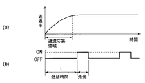
また、(b)において、時間T0で走査線の1行目に左眼用映像が表示され始めると、液晶の性質上所望の透過率に達するまでの時間(過渡応答時間)を考慮し(図3参照)、1行目の走査線に対応するバックライトは、遅延時間tを経過した後に点灯され始め、左眼用映像が終了(黒像の書き込み開始前)するまでのtBLの間で点灯される((d)参照)。 In (b), when the left-eye image starts to be displayed in the first line of the scanning line at time T 0 , the time required to reach a desired transmittance (transient response time) due to the properties of the liquid crystal is considered ( (Refer to FIG. 3) The backlight corresponding to the scanning line of the first row starts to be turned on after the delay time t has elapsed, and during t BL until the left-eye video ends (before the start of black image writing). Is lit (see (d)).
同様にして、パネルの中央部領域(((n/3)+1)〜(2n/3))に対応するk行目の走査線においても、時間T0の(k−1)Δt後に左眼用映像が表示され始めるが、k行目の走査線に対応するバックライトは、さらに遅延時間tを経過した後に点灯され始め、左眼用映像が終了(黒像の書き込み開始前)するまでのtBLの間で点灯される((e)参照)。 Similarly, in the k-th scanning line corresponding to the central region (((n / 3) +1) to (2n / 3)) of the panel, the left eye after (k−1) Δt at time T 0. The backlight corresponding to the k-th scanning line starts to be turned on after the delay time t has elapsed, and the left-eye video is finished (before the start of black image writing). It is turned on between t BL ((e) reference).
これに対して、パネル下部領域(((2n/3)+1)〜n)であるr(r≧((2n/3)+1)、r<n)、・・・n行目の各走査線においては、時間T0の(r−1)Δt後に左眼用映像が表示され始めると、n=r、・・・x行目の走査線に対応するバックライトは、遅延時間t’(t’<t)を経過した後に一斉に点灯され始め、tBL’(tBL’>tBL)経過後、一斉に消灯される。 On the other hand, r (r ≧ ((2n / 3) +1), r <n),..., Each scanning line in the lower panel region (((2n / 3) +1) to n) , When the left-eye video starts to be displayed after (r−1) Δt of time T 0 , the backlight corresponding to the scanning line of n = r,. After '<t) has elapsed, the LEDs start to be turned on all at once, and after t BL' (t BL ' > t BL ) has passed, the lights are turned off all at once.
これは、(c)に示すように、T2で左眼用眼鏡シャッタがONからOFFへと切替る一方、右眼用眼鏡シャッタがOFFからONとされて、右眼用映像が認識可能となるため、(b)においてZで示す領域のバックライトを一斉に消灯して、観察者が左右眼両映像を混在して認識(3Dクロストークが発生)しないようにするためである。 This is because, as shown in (c), one for the left eye eyeglass shutter Ru switched from ON to OFF at T 2, the right-eye glasses shutter is turned ON from OFF, the right eye image and recognizable Therefore, the backlights of the area indicated by Z in (b) are turned off all at once, so that the observer does not recognize both the left and right eye images together (3D crosstalk occurs).
また、バックライトを点灯している時間の割合(BL Duty=tBL/(t+tBL+tBK))は、パネル上部領域、中央部領域共に従来と同様25%とされているが、パネル下部領域のr、・・・nの走査線に対応する領域では、BL Duty=33%とされている。 In addition, the ratio of time during which the backlight is lit (BL Duty = t BL / (t + t BL + t BK )) is 25% in the upper panel area and the central area as in the conventional case, but the lower panel area In the region corresponding to the r,..., N scanning lines, BL Duty = 33%.
本実施の形態の立体映像表示装置においては、バックライトの点灯Dutyをパネル面内で異ならせ、パネル下部領域のr、・・・nの走査線に対応する領域のBL Dutyをパネル上部領域及び中央部領域よりも高く設定しているので、3Dクロストークの発生を防止するためにZで示す領域の部分でバックライトを消灯させても、パネル下部領域が暗くなることがなく、輝度傾斜の発生を抑制することができる。 In the stereoscopic image display apparatus according to the present embodiment, the backlight lighting duty is varied within the panel surface, and the BL duty of the region corresponding to the r,... Since it is set higher than the central area, even if the backlight is turned off in the area indicated by Z in order to prevent the occurrence of 3D crosstalk, the lower area of the panel does not become dark, Occurrence can be suppressed.
また、例えば、本実施形態によれば、上記したように、液晶素子の液晶層及び光シャッタ液晶素子9に用いられる液晶材料として、それぞれ高速応答が可能なOCB液晶を用いると共に、左右映像間に黒挿入を施し、更にパネルの走査と同期したスキャンバックライトを組み合わせることで、0°視角(正面方向)での3Dクロストーク率を、表示上、全く問題とならない2%以下(より好ましくは0.5%以下)、更には0.1%以下である0.08%とすることができた。更に、60°視角での3Dクロストーク率も、2%以下(より好ましくは0.5%以下)である、0.14%とすることができた。
Further, for example, according to the present embodiment, as described above, OCB liquid crystal capable of high-speed response is used as the liquid crystal material used for the liquid crystal layer of the liquid crystal element and the optical shutter
なお、ここで用いるクロストーク率は、輝度計、ゴニオンメータを用い、(B−C)/A×100%(A:左右映像のそれぞれが白表示された状態での左眼(あるいは右眼)に入射される輝度、B:左映像が黒表示、右映像が白表示時に左眼(あるいは右眼)に入射される輝度、C:左右映像のそれぞれが黒表示状態での左眼(あるいは右眼)に入射される輝度)で算出される値を用いた。 The crosstalk rate used here is (BC) / A × 100% (A: left eye (or right eye) in a state where each of the left and right images is displayed in white) using a luminance meter and a goniometer. Incident luminance, B: Luminance incident on the left eye (or right eye) when the left image is displayed in black and right image is displayed in white, and C: Left eye (or right eye) when the left and right images are displayed in black. The value calculated in (the luminance incident on) is used.
更に、この実施形態によれば、スキャンバックライトの点灯制御により、画面内での輝度傾斜が生じることも解消された。 Furthermore, according to this embodiment, the occurrence of a luminance gradient in the screen due to the lighting control of the scan backlight is also eliminated.
なお、バックライトの点灯期間(tBL,tBL’)は、観察者の嗜好に応じて、例えば明るさを重視するのであれば長く設定する等、適宜調整可能としてもかまわない。 Note that the backlight lighting period (t BL , t BL ′ ) may be appropriately adjusted according to the preference of the observer, for example, by setting a longer period if brightness is important.
また、黒像が表示される期間(tBK)についても、観察者の嗜好に応じて、例えば動画表示を重視するのであれば長く、明るさを重視するのであれば短く設定する等、適宜調整可能としてもかまわない。 Also, the period (t BK ) during which the black image is displayed is appropriately adjusted according to the preference of the observer, for example, if the video display is emphasized, the period is long, and if the brightness is important, the period is set short. It does not matter if possible.
(第2の実施の形態)
第1の実施の形態と同様に図1に示す立体映像表示装置10を用いた立体映像表示方法の第2の実施の形態について、図4に基づいて説明する。
(Second Embodiment)
Similar to the first embodiment, a second embodiment of a stereoscopic video display method using the stereoscopic video display device 10 shown in FIG. 1 will be described with reference to FIG.
本実施の形態においても、図4(a)に示すように、時間T0で走査線の1行目に左眼用映像が表示され始めると、1行目の走査線に対応するバックライトは、遅延時間tを経過した後に点灯され始め、左眼用映像が終了(黒像の書き込み開始前)するまでのtBLの間で点灯される。また、パネルの中央部領域であるk行目の走査線においても、時間T0の(k−1)Δt後に左眼用映像が表示され始めるが、k行目の走査線に対応するバックライトは、さらに遅延時間tを経過した後に点灯され始め、左眼用映像が終了(黒像の書き込み開始前)するまでのtBLの間で点灯される。更に、パネル下部領域であるr(r≧((2n/3)+1)、r<n)、・・・n行目の各走査線においては、時間T0の(r−1)Δt後に左眼用映像が表示され始めると、r、・・・n行目の走査線に対応するバックライトは、遅延時間t’(t’<t)を経過した後に一斉に点灯され始め、tBL’(tBL’>tBL)経過後、一斉に消灯される。 Also in the present embodiment, as shown in FIG. 4A, when the left-eye video starts to be displayed on the first line of the scanning line at time T 0 , the backlight corresponding to the first scanning line is After the delay time t elapses, the lighting starts, and the lighting is performed for t BL until the left-eye video ends (before the black image writing starts). Also, the left-eye image starts to be displayed after (k−1) Δt at time T 0 in the k-th scanning line that is the central region of the panel, but the backlight corresponding to the k-th scanning line is displayed. Starts to be turned on after the elapse of the delay time t, and is turned on for tBL until the left-eye video is finished (before the start of writing the black image). Further, r (r ≧ ((2n / 3) +1), r <n),..., Nth scanning line, which is the lower panel region, is left after (r−1) Δt of time T 0. When the eye image starts to be displayed, the backlights corresponding to the scanning lines in the r,..., Nth row start to be turned on simultaneously after the delay time t ′ (t ′ <t) has elapsed, and t BL ′. After (t BL ′ > t BL ) elapses, the lights are turned off all at once.
また、バックライトを点灯している時間の割合(BL Duty=tBL/(t+tBL+tBK))は、パネル上部領域、中央部領域共に25%とされているが、パネル下部領域(走査線n=r、・・・x)では、33%とされている点も第1の実施の形態と同様である。 Further, the ratio of the time during which the backlight is lit (BL Duty = t BL / (t + t BL + t BK )) is 25% in both the upper panel area and the central area, but the lower panel area (scanning line) In the case of n = r,... x), the point being 33% is the same as in the first embodiment.
しかし、本実施の形態では、左眼用映像が表示されているパネル下部領域(走査線r、・・・n)のバックライトが消灯してから、1行目の走査線に右眼用映像のバックライトが表示されるまでの時間tYで表わされるYで示される領域において、液晶パネルの全ての領域におけるバックライトが消灯されている。 However, in this embodiment, after the backlight of the lower panel area (scanning lines r,... N) where the left-eye video is displayed is turned off, the right-eye video is displayed on the first scanning line. In the area indicated by Y represented by the time t Y until the backlight is displayed, the backlight in all areas of the liquid crystal panel is turned off.
この時間tYは、(c)で示すように、左眼用眼鏡シャッタがONからOFFにされる際の液晶の透過率が初期の状態に戻る応答時間、及び右眼用眼鏡シャッタがOFFからONにされる際に液晶の透過率が所望の値に立ち上がるまでの応答時間を考慮して決定される。 This time t Y is the response time for the liquid crystal transmittance to return to the initial state when the left eyeglass shutter is turned from ON to OFF, and the right eyeglass shutter from OFF, as shown in (c). It is determined in consideration of the response time until the transmittance of the liquid crystal rises to a desired value when turned on.
従来、眼鏡シャッタの一方をOFFにしても、液晶の過渡応答性によりバックライトが点灯した際に3Dクロストークが発生することがあったが、本実施の形態によれば、液晶の過渡応答特性を考慮し、この間、液晶パネルの全ての領域におけるバックライトを消灯させているので、3Dクロストークの発生をより一層、効果的に防止することができる。 Conventionally, even when one of the eyeglass shutters is turned off, 3D crosstalk sometimes occurs when the backlight is turned on due to the transient response of the liquid crystal. According to the present embodiment, the transient response characteristic of the liquid crystal In consideration of this, the backlight in all areas of the liquid crystal panel is turned off during this period, so that the occurrence of 3D crosstalk can be more effectively prevented.
(第3の実施の形態)
第1の実施の形態と同様に図1に示す立体映像表示装置10を用いた立体映像表示方法の第3の実施の形態について、図5〜図7に基づいて説明する。
(Third embodiment)
As in the first embodiment, a third embodiment of a stereoscopic video display method using the stereoscopic video display device 10 shown in FIG. 1 will be described with reference to FIGS.
本実施の形態においては、第1の実施の形態におけるパネル上部領域(1・・・(n/3))の走査線に対応するバックライトの発光量を大きくした以外は、第1の実施の形態と同様に動作される。 In the present embodiment, the first embodiment is the same as the first embodiment except that the light emission amount of the backlight corresponding to the scanning line of the panel upper region (1... (N / 3)) in the first embodiment is increased. Operates in the same way as the form.
上記の立体表示装置において、図5(a)に示すパネル中央部領域であるk行目の走査線に対応するバックライトの発光量を(b)に示すように面積Aで表すと、k行目の走査線に右眼用映像が表示され始めてからの液晶の応答性は(c)で示され、右眼用眼鏡シャッタがONされてからの液晶の応答性は(d)で示されるため、観察者がk行目の走査線を見た場合の輝度は、(b)に示すバックライトの発光量Aに、(c)で示すパネル中央部の液晶の応答性と、(d)で示す右眼用眼鏡シャッタの液晶の応答性を乗じた(e)で示す面積Bで示されることになる。 In the above-described stereoscopic display device, if the light emission amount of the backlight corresponding to the k-th scanning line which is the panel central region shown in FIG. 5A is represented by area A as shown in FIG. The response of the liquid crystal after the right eye image starts to be displayed on the eye scanning line is indicated by (c), and the response of the liquid crystal after the right eyeglass shutter is turned on is indicated by (d). The luminance when the observer looks at the scanning line of the k-th line is the light emission amount A of the backlight shown in (b), the responsiveness of the liquid crystal at the center of the panel shown in (c), and (d) The area B shown by (e) multiplied by the response of the liquid crystal of the right eyeglass shutter shown.
これに対して、図6(a)に示すパネル上部領域である1行目の走査線に対応するバックライトの発光量をパネル中央部領域と等しくして、図5(b)と同様に面積Aで表すと、1行目の走査線に右眼用映像が表示され始めてからの液晶の応答性は(c)で示され、右眼用眼鏡シャッタがONされてからの液晶の応答性は(d)で示されるため、観察者が1行目の走査線を見た場合の輝度は、(b)に示すバックライトの発光量Aに、(c)で示すパネル上部の液晶の応答性と、(d)で示す右眼用眼鏡シャッタの液晶の応答性を乗じた(e)で示す面積Cで示されることになる。 On the other hand, the light emission amount of the backlight corresponding to the scanning line of the first row which is the panel upper region shown in FIG. 6A is made equal to the panel central region, and the area is the same as in FIG. When represented by A, the response of the liquid crystal after the right-eye image starts to be displayed on the first scanning line is indicated by (c), and the response of the liquid crystal after the right-eye glasses shutter is turned on is Since it is shown by (d), the brightness when the observer looks at the scanning line of the first row is the responsiveness of the liquid crystal at the top of the panel shown in (c) to the light emission amount A of the backlight shown in (b). And the area C shown by (e) multiplied by the response of the liquid crystal of the right eyeglass shutter shown by (d).
図5に示すように、液晶パネルの中央部領域では、(c)に示すように液晶が十分に応答して透過率が高くなり、かつ右眼用眼鏡シャッタの液晶も(d)に示すように透過率が高くなってからバックライトが点灯するため、輝度は当初の領域Aの面積からそれほど低下しないが(図5(e)の領域Bの面積を参照)、これに対して、液晶パネルの上部領域では、図6(d)に示すように、右眼用眼鏡シャッタの液晶が応答段階にあり透過率が十分に高くない状態でバックライトが点灯するため、輝度は当初の領域Aの面積(図6(b))から領域Cの面積(図9(e))へと低下してしまう。 As shown in FIG. 5, in the central region of the liquid crystal panel, the liquid crystal sufficiently responds to increase the transmittance as shown in (c), and the liquid crystal of the right eyeglass shutter also shows in (d). Since the backlight is turned on after the transmittance becomes high, the luminance does not decrease so much from the area of the initial region A (see the area of the region B in FIG. 5E). In the upper region, as shown in FIG. 6 (d), the backlight is lit in a state where the liquid crystal of the right eyeglass shutter is in a response stage and the transmittance is not sufficiently high. The area (FIG. 6B) decreases to the area C area (FIG. 9E).
しかしながら、本実施の形態においては、図7(a)に示すパネル上部領域の走査線に対応するバックライトの発光量を、同図(b)に示すように、図6(b)の発光量と比較して1.5倍大きくしている。 However, in the present embodiment, the light emission amount of the backlight corresponding to the scanning line in the panel upper region shown in FIG. 7A is the light emission amount of FIG. 6B as shown in FIG. It is 1.5 times larger than
このため、例えば、1行目の走査線に右眼用映像が表示され始めてからの液晶の応答性は図7(c)で示され、右眼用眼鏡シャッタがONされてからの液晶の応答性は同図(d)で示されるため、観察者が1行目の走査線を見た場合の輝度は、同図(b)に示すバックライトの発光量Aに、同図(c)で示すパネル上部の液晶の応答性と、同図(d)で示す右眼用眼鏡シャッタの液晶の応答性を乗じた同図(e)で示す面積C’で示されることになる。 For this reason, for example, the response of the liquid crystal after the right-eye image starts to be displayed on the first scanning line is shown in FIG. 7C, and the response of the liquid crystal after the right-eye glasses shutter is turned on. Therefore, the luminance when the observer looks at the first scanning line is equal to the light emission amount A of the backlight shown in FIG. The area C ′ shown in FIG. 5E is obtained by multiplying the responsiveness of the liquid crystal at the upper portion of the panel shown by the responsiveness of the liquid crystal of the right eyeglass shutter shown in FIG.
この面積C’は,図5(e)に示す面積Bとほぼ等しい面積となるため、パネル上部の輝度は、観察者がパネル中央部を見た場合の輝度とほぼ等しくなり、液晶シャッタのONタイミングとパネル応答のパネル面内のONタイミングの違いに起因する輝度傾斜を抑制することができる。 Since the area C ′ is substantially equal to the area B shown in FIG. 5E, the luminance at the top of the panel is almost equal to the luminance when the observer looks at the center of the panel, and the liquid crystal shutter is turned on. It is possible to suppress the luminance gradient caused by the difference between the timing and the panel response ON timing within the panel surface.
液晶パネル上部のバックライトの発光量を増大させるには、この部分に対応するバックライトのLED電流を高くすること等により達成することができる。 Increasing the amount of light emitted from the backlight at the top of the liquid crystal panel can be achieved by increasing the LED current of the backlight corresponding to this portion.
(その他の実施の形態)
第1の実施の形態乃至第3の実施の形態では、液晶パネルにおいて右眼用映像及び左眼用映像を表示する間に所定幅(25%)の黒像を表示する例を示したが、黒像を挿入する幅は適宜変更できる。また、黒像を省略して、右眼用映像及び左眼用映像のみを表示しても良い。
(Other embodiments)
In the first to third embodiments, an example in which a black image having a predetermined width (25%) is displayed while the right-eye video and the left-eye video are displayed on the liquid crystal panel has been described. The width for inserting the black image can be changed as appropriate. Alternatively, the black image may be omitted and only the right eye video and the left eye video may be displayed.
更に、液晶パネルに表示される黒像は所定の幅ではなく、時間と共に黒像の表示幅が変化する表示手法を用いても良い。 Further, the black image displayed on the liquid crystal panel may be a display method in which the display width of the black image changes with time instead of a predetermined width.
1:スキャンコンバータ、2:液晶パネル、3:バックライト、5:液晶シャッタ駆動回路、7:眼鏡シャッタ、9:光シャッタ液晶素子、10:立体映像表示装置 1: Scan converter, 2: Liquid crystal panel, 3: Backlight, 5: Liquid crystal shutter drive circuit, 7: Glasses shutter, 9: Optical shutter liquid crystal element, 10: Stereoscopic image display device
Claims (2)
前記液晶パネルを照明するバックライトと、
左眼部と右眼部にそれぞれ液晶素子を有する眼鏡シャッタと、
前記液晶パネル及び前記眼鏡シャッタを同期して駆動させる液晶シャッタ駆動回路と、を備え、
前記液晶パネルの前記各領域に左右眼用映像のいずれかが表示されてから所定時間経過後に対応するバックライトが点灯し、前記下部領域に対応して点灯するバックライトの点灯期間と、後行して点灯する前記上部領域の点灯期間が重複せず、更に、前記下部領域の少なくとも一部の走査線に対応するバックライトを直前の走査線に対応するバックライトよりも先行発光させることにより、その点灯時間割合を、他の部分の走査線に対応する前記バックライトの点灯時間割合よりも大きくしたことを特徴とする立体映像表示装置。 It is composed of a plurality of active matrix liquid crystal elements and consists of n scanning lines extending in the row direction, and is divided into at least three regions, an upper region, a central region, and a lower region. A liquid crystal panel that displays images for the left and right eyes in a time-division manner by scanning in the column direction;
A backlight for illuminating the liquid crystal panel;
Glasses shutters having liquid crystal elements in the left eye part and the right eye part,
A liquid crystal shutter driving circuit for driving the liquid crystal panel and the eyeglass shutter synchronously,
The corresponding backlight is turned on after a lapse of a predetermined time since any one of the left and right eye images is displayed in each area of the liquid crystal panel, and the backlight lighting period that is turned on corresponding to the lower area, and the following The lighting period of the upper region that is turned on does not overlap, and further, by causing the backlight corresponding to at least a part of the scanning lines of the lower region to emit light earlier than the backlight corresponding to the immediately preceding scanning line, A stereoscopic video display apparatus characterized in that the lighting time ratio is made larger than the lighting time ratio of the backlight corresponding to the scanning lines of other portions.
前記液晶パネルを照明するバックライトと、 左眼部と右眼部にそれぞれ液晶素子を有する眼鏡シャッタと、 A backlight for illuminating the liquid crystal panel; glasses shutters each having a liquid crystal element in the left eye part and the right eye part;
前記液晶パネル及び前記眼鏡シャッタを同期して駆動させる液晶シャッタ駆動回路と、を備え、 A liquid crystal shutter driving circuit for driving the liquid crystal panel and the eyeglass shutter synchronously,
前記液晶パネルにおける前記上部領域の走査線の少なくとも一部に対応する前記バックライトの発光量を、他の部分の走査線に対応する前記バックライトの発光量よりも大きくしたことを特徴とする立体映像表示装置。 A volume of light emitted from the backlight corresponding to at least a part of the scanning lines in the upper region of the liquid crystal panel is made larger than that emitted from the backlight corresponding to the scanning lines in other parts. Video display device.
Priority Applications (1)
| Application Number | Priority Date | Filing Date | Title |
|---|---|---|---|
| JP2009130516A JP5436050B2 (en) | 2009-05-29 | 2009-05-29 | 3D image display device |
Applications Claiming Priority (1)
| Application Number | Priority Date | Filing Date | Title |
|---|---|---|---|
| JP2009130516A JP5436050B2 (en) | 2009-05-29 | 2009-05-29 | 3D image display device |
Publications (3)
| Publication Number | Publication Date |
|---|---|
| JP2010276928A JP2010276928A (en) | 2010-12-09 |
| JP2010276928A5 JP2010276928A5 (en) | 2012-07-05 |
| JP5436050B2 true JP5436050B2 (en) | 2014-03-05 |
Family
ID=43423938
Family Applications (1)
| Application Number | Title | Priority Date | Filing Date |
|---|---|---|---|
| JP2009130516A Active JP5436050B2 (en) | 2009-05-29 | 2009-05-29 | 3D image display device |
Country Status (1)
| Country | Link |
|---|---|
| JP (1) | JP5436050B2 (en) |
Cited By (2)
| Publication number | Priority date | Publication date | Assignee | Title |
|---|---|---|---|---|
| CN109166536A (en) * | 2018-11-07 | 2019-01-08 | 惠科股份有限公司 | Brightness adjusting method, brightness control system and the display system of display system |
| CN109166534A (en) * | 2018-11-07 | 2019-01-08 | 惠科股份有限公司 | Brightness adjusting method, brightness control system and the display system of display system |
Families Citing this family (13)
| Publication number | Priority date | Publication date | Assignee | Title |
|---|---|---|---|---|
| WO2011033674A1 (en) * | 2009-09-18 | 2011-03-24 | 株式会社 東芝 | 3d image display apparatus |
| WO2012001850A1 (en) * | 2010-06-28 | 2012-01-05 | シャープ株式会社 | Liquid crystal display apparatus and scan backlight control method |
| JP2012128197A (en) * | 2010-12-15 | 2012-07-05 | Toshiba Corp | Stereoscopic image display device and stereoscopic image display method |
| JP5910042B2 (en) * | 2010-12-17 | 2016-04-27 | ソニー株式会社 | Illumination device and display device |
| WO2012081497A1 (en) * | 2010-12-17 | 2012-06-21 | ソニー株式会社 | Illumination device, display device and three-dimensional display device |
| JP5693246B2 (en) * | 2011-01-07 | 2015-04-01 | キヤノン株式会社 | 3D image display device |
| KR20120109158A (en) * | 2011-03-28 | 2012-10-08 | 삼성디스플레이 주식회사 | Display system |
| TWI478137B (en) * | 2011-04-27 | 2015-03-21 | Sony Corp | Display device |
| JP5990743B2 (en) | 2012-03-09 | 2016-09-14 | 株式会社Joled | Organic EL display device and driving method thereof |
| JP6099884B2 (en) | 2012-05-25 | 2017-03-22 | 三菱電機株式会社 | Stereoscopic image display device |
| JP5950692B2 (en) | 2012-05-25 | 2016-07-13 | 三菱電機株式会社 | Stereoscopic image display device |
| WO2014181690A1 (en) | 2013-05-08 | 2014-11-13 | 堺ディスプレイプロダクト株式会社 | Display device and display system |
| US9842547B2 (en) | 2013-05-08 | 2017-12-12 | Sakai Display Products Corporation | Display apparatus and television receiver |
Family Cites Families (5)
| Publication number | Priority date | Publication date | Assignee | Title |
|---|---|---|---|---|
| JPS6261493A (en) * | 1985-09-11 | 1987-03-18 | Toshiba Corp | Picture display device for stereoscopic vision |
| US8659641B2 (en) * | 2007-05-18 | 2014-02-25 | 3M Innovative Properties Company | Stereoscopic 3D liquid crystal display apparatus with black data insertion |
| JP5503549B2 (en) * | 2007-11-28 | 2014-05-28 | コーニンクレッカ フィリップス エヌ ヴェ | 3D visualization |
| JP4775464B2 (en) * | 2009-03-13 | 2011-09-21 | ソニー株式会社 | Image display device, image display observation system, and image display method |
| JP2010243705A (en) * | 2009-04-03 | 2010-10-28 | Hitachi Ltd | Stereoscopic display |
-
2009
- 2009-05-29 JP JP2009130516A patent/JP5436050B2/en active Active
Cited By (3)
| Publication number | Priority date | Publication date | Assignee | Title |
|---|---|---|---|---|
| CN109166536A (en) * | 2018-11-07 | 2019-01-08 | 惠科股份有限公司 | Brightness adjusting method, brightness control system and the display system of display system |
| CN109166534A (en) * | 2018-11-07 | 2019-01-08 | 惠科股份有限公司 | Brightness adjusting method, brightness control system and the display system of display system |
| CN109166536B (en) * | 2018-11-07 | 2020-11-24 | 惠科股份有限公司 | Brightness adjusting method and system of display system and display system |
Also Published As
| Publication number | Publication date |
|---|---|
| JP2010276928A (en) | 2010-12-09 |
Similar Documents
| Publication | Publication Date | Title |
|---|---|---|
| JP5436050B2 (en) | 3D image display device | |
| JP5589311B2 (en) | Video display device and video display system | |
| JP4779020B2 (en) | Display device | |
| US9224323B2 (en) | Systems and methods for increasing spatial or temporal resolution for dual modulated display systems | |
| KR100623726B1 (en) | Stereopsis Liquid Crystal Display Device in Field-Sequential Driving and Method of Driving the same | |
| JP6099884B2 (en) | Stereoscopic image display device | |
| JP5252223B2 (en) | Video display device and video display system | |
| EP2579240B1 (en) | Liquid crystal display device and television receiver | |
| US20120113159A1 (en) | Stereoscopic display apparatus and display method for stereoscopic display apparatus | |
| US9548013B2 (en) | Image display device and drive method therefor | |
| KR101460171B1 (en) | Optical member , backlight assembly having the same and display apparatus | |
| JP6153290B2 (en) | Image display device and display box using the same | |
| JP2012013980A (en) | Stereoscopic display device and display drive circuit | |
| JP4889332B2 (en) | Video display device | |
| US9620044B2 (en) | Image display device and drive method therefor | |
| US20110221788A1 (en) | Liquid crystal display and picture display system | |
| TWI363192B (en) | Stereo-image displaying apparatus and method for reducing stereo-image cross-talk | |
| WO2018181908A1 (en) | Display apparatus and head-mounted display | |
| JP5506205B2 (en) | 3D display device | |
| JP2011075979A (en) | Stereoscopic video display device | |
| JP2019128553A (en) | Display device | |
| JP2013126248A (en) | Method of displaying three-dimensional stereoscopic image and display apparatus for performing the same | |
| US11561441B2 (en) | Display apparatus including a plurality of display panels, and method of controlling thereof | |
| WO2012073795A1 (en) | Display device, method for driving same, and electronic apparatus | |
| JP2013251792A (en) | Liquid crystal display device |
Legal Events
| Date | Code | Title | Description |
|---|---|---|---|
| RD04 | Notification of resignation of power of attorney |
Free format text: JAPANESE INTERMEDIATE CODE: A7424 Effective date: 20110422 |
|
| A521 | Request for written amendment filed |
Free format text: JAPANESE INTERMEDIATE CODE: A523 Effective date: 20120517 |
|
| A621 | Written request for application examination |
Free format text: JAPANESE INTERMEDIATE CODE: A621 Effective date: 20120517 |
|
| A977 | Report on retrieval |
Free format text: JAPANESE INTERMEDIATE CODE: A971007 Effective date: 20130131 |
|
| A131 | Notification of reasons for refusal |
Free format text: JAPANESE INTERMEDIATE CODE: A131 Effective date: 20130611 |
|
| A711 | Notification of change in applicant |
Free format text: JAPANESE INTERMEDIATE CODE: A711 Effective date: 20130624 |
|
| A711 | Notification of change in applicant |
Free format text: JAPANESE INTERMEDIATE CODE: A712 Effective date: 20130624 |
|
| A521 | Request for written amendment filed |
Free format text: JAPANESE INTERMEDIATE CODE: A523 Effective date: 20130805 |
|
| RD03 | Notification of appointment of power of attorney |
Free format text: JAPANESE INTERMEDIATE CODE: A7423 Effective date: 20130909 |
|
| TRDD | Decision of grant or rejection written | ||
| A01 | Written decision to grant a patent or to grant a registration (utility model) |
Free format text: JAPANESE INTERMEDIATE CODE: A01 Effective date: 20131204 |
|
| A61 | First payment of annual fees (during grant procedure) |
Free format text: JAPANESE INTERMEDIATE CODE: A61 Effective date: 20131210 |
|
| R150 | Certificate of patent or registration of utility model |
Ref document number: 5436050 Country of ref document: JP Free format text: JAPANESE INTERMEDIATE CODE: R150 Free format text: JAPANESE INTERMEDIATE CODE: R150 |
|
| R250 | Receipt of annual fees |
Free format text: JAPANESE INTERMEDIATE CODE: R250 |
|
| R250 | Receipt of annual fees |
Free format text: JAPANESE INTERMEDIATE CODE: R250 |
|
| R250 | Receipt of annual fees |
Free format text: JAPANESE INTERMEDIATE CODE: R250 |
|
| R250 | Receipt of annual fees |
Free format text: JAPANESE INTERMEDIATE CODE: R250 |
|
| R250 | Receipt of annual fees |
Free format text: JAPANESE INTERMEDIATE CODE: R250 |
|
| R250 | Receipt of annual fees |
Free format text: JAPANESE INTERMEDIATE CODE: R250 |
|
| R250 | Receipt of annual fees |
Free format text: JAPANESE INTERMEDIATE CODE: R250 |
|
| R250 | Receipt of annual fees |
Free format text: JAPANESE INTERMEDIATE CODE: R250 |