JP5435943B2 - Dynamic fixing device - Google Patents
Dynamic fixing device Download PDFInfo
- Publication number
- JP5435943B2 JP5435943B2 JP2008518436A JP2008518436A JP5435943B2 JP 5435943 B2 JP5435943 B2 JP 5435943B2 JP 2008518436 A JP2008518436 A JP 2008518436A JP 2008518436 A JP2008518436 A JP 2008518436A JP 5435943 B2 JP5435943 B2 JP 5435943B2
- Authority
- JP
- Japan
- Prior art keywords
- segment
- fixation device
- dynamic fixation
- rod
- arm
- Prior art date
- Legal status (The legal status is an assumption and is not a legal conclusion. Google has not performed a legal analysis and makes no representation as to the accuracy of the status listed.)
- Expired - Fee Related
Links
Images


Classifications
-
- A—HUMAN NECESSITIES
- A61—MEDICAL OR VETERINARY SCIENCE; HYGIENE
- A61B—DIAGNOSIS; SURGERY; IDENTIFICATION
- A61B17/00—Surgical instruments, devices or methods, e.g. tourniquets
- A61B17/56—Surgical instruments or methods for treatment of bones or joints; Devices specially adapted therefor
- A61B17/58—Surgical instruments or methods for treatment of bones or joints; Devices specially adapted therefor for osteosynthesis, e.g. bone plates, screws, setting implements or the like
- A61B17/68—Internal fixation devices, including fasteners and spinal fixators, even if a part thereof projects from the skin
- A61B17/70—Spinal positioners or stabilisers ; Bone stabilisers comprising fluid filler in an implant
- A61B17/7001—Screws or hooks combined with longitudinal elements which do not contact vertebrae
- A61B17/7002—Longitudinal elements, e.g. rods
- A61B17/7011—Longitudinal element being non-straight, e.g. curved, angled or branched
-
- A—HUMAN NECESSITIES
- A61—MEDICAL OR VETERINARY SCIENCE; HYGIENE
- A61B—DIAGNOSIS; SURGERY; IDENTIFICATION
- A61B17/00—Surgical instruments, devices or methods, e.g. tourniquets
- A61B17/56—Surgical instruments or methods for treatment of bones or joints; Devices specially adapted therefor
-
- A—HUMAN NECESSITIES
- A61—MEDICAL OR VETERINARY SCIENCE; HYGIENE
- A61B—DIAGNOSIS; SURGERY; IDENTIFICATION
- A61B17/00—Surgical instruments, devices or methods, e.g. tourniquets
- A61B17/56—Surgical instruments or methods for treatment of bones or joints; Devices specially adapted therefor
- A61B17/58—Surgical instruments or methods for treatment of bones or joints; Devices specially adapted therefor for osteosynthesis, e.g. bone plates, screws, setting implements or the like
- A61B17/68—Internal fixation devices, including fasteners and spinal fixators, even if a part thereof projects from the skin
- A61B17/70—Spinal positioners or stabilisers ; Bone stabilisers comprising fluid filler in an implant
- A61B17/7001—Screws or hooks combined with longitudinal elements which do not contact vertebrae
- A61B17/7002—Longitudinal elements, e.g. rods
- A61B17/7019—Longitudinal elements having flexible parts, or parts connected together, such that after implantation the elements can move relative to each other
- A61B17/7023—Longitudinal elements having flexible parts, or parts connected together, such that after implantation the elements can move relative to each other with a pivot joint
-
- A—HUMAN NECESSITIES
- A61—MEDICAL OR VETERINARY SCIENCE; HYGIENE
- A61B—DIAGNOSIS; SURGERY; IDENTIFICATION
- A61B17/00—Surgical instruments, devices or methods, e.g. tourniquets
- A61B17/56—Surgical instruments or methods for treatment of bones or joints; Devices specially adapted therefor
- A61B17/58—Surgical instruments or methods for treatment of bones or joints; Devices specially adapted therefor for osteosynthesis, e.g. bone plates, screws, setting implements or the like
- A61B17/68—Internal fixation devices, including fasteners and spinal fixators, even if a part thereof projects from the skin
- A61B17/70—Spinal positioners or stabilisers ; Bone stabilisers comprising fluid filler in an implant
- A61B17/7001—Screws or hooks combined with longitudinal elements which do not contact vertebrae
- A61B17/7002—Longitudinal elements, e.g. rods
- A61B17/7019—Longitudinal elements having flexible parts, or parts connected together, such that after implantation the elements can move relative to each other
- A61B17/7026—Longitudinal elements having flexible parts, or parts connected together, such that after implantation the elements can move relative to each other with a part that is flexible due to its form
-
- A—HUMAN NECESSITIES
- A61—MEDICAL OR VETERINARY SCIENCE; HYGIENE
- A61F—FILTERS IMPLANTABLE INTO BLOOD VESSELS; PROSTHESES; DEVICES PROVIDING PATENCY TO, OR PREVENTING COLLAPSING OF, TUBULAR STRUCTURES OF THE BODY, e.g. STENTS; ORTHOPAEDIC, NURSING OR CONTRACEPTIVE DEVICES; FOMENTATION; TREATMENT OR PROTECTION OF EYES OR EARS; BANDAGES, DRESSINGS OR ABSORBENT PADS; FIRST-AID KITS
- A61F2/00—Filters implantable into blood vessels; Prostheses, i.e. artificial substitutes or replacements for parts of the body; Appliances for connecting them with the body; Devices providing patency to, or preventing collapsing of, tubular structures of the body, e.g. stents
- A61F2/02—Prostheses implantable into the body
- A61F2/30—Joints
- A61F2/44—Joints for the spine, e.g. vertebrae, spinal discs
-
- A—HUMAN NECESSITIES
- A61—MEDICAL OR VETERINARY SCIENCE; HYGIENE
- A61B—DIAGNOSIS; SURGERY; IDENTIFICATION
- A61B17/00—Surgical instruments, devices or methods, e.g. tourniquets
- A61B17/56—Surgical instruments or methods for treatment of bones or joints; Devices specially adapted therefor
- A61B17/58—Surgical instruments or methods for treatment of bones or joints; Devices specially adapted therefor for osteosynthesis, e.g. bone plates, screws, setting implements or the like
- A61B17/68—Internal fixation devices, including fasteners and spinal fixators, even if a part thereof projects from the skin
- A61B17/70—Spinal positioners or stabilisers ; Bone stabilisers comprising fluid filler in an implant
- A61B17/7001—Screws or hooks combined with longitudinal elements which do not contact vertebrae
- A61B17/7002—Longitudinal elements, e.g. rods
- A61B17/7004—Longitudinal elements, e.g. rods with a cross-section which varies along its length
- A61B17/7007—Parts of the longitudinal elements, e.g. their ends, being specially adapted to fit around the screw or hook heads
-
- A—HUMAN NECESSITIES
- A61—MEDICAL OR VETERINARY SCIENCE; HYGIENE
- A61B—DIAGNOSIS; SURGERY; IDENTIFICATION
- A61B17/00—Surgical instruments, devices or methods, e.g. tourniquets
- A61B2017/00004—(bio)absorbable, (bio)resorbable, resorptive
Description
本発明は、一般に、固定器具に関し、特に、椎骨を互いに屈曲可能に固定できる器具に関する。 The present invention relates generally to fixation devices, and more particularly to devices that are capable of flexibly fixing vertebrae to one another.
腰椎は、通常の活動中における応力及び運動のうちの非常に多くの量を吸収する。人口の大部分に関し、体の治癒反応は、傷害、摩耗及び老化の累積的効果に先行する場合があるが、ほどほどの機能を備えた安定性を依然として維持することができる。しかしながら、場合によっては、外傷又は応力が、体の治癒能力を上回り、それにより局所破損及び過剰の摩耗を招き、又、局所不安定性をもたらす場合が多い。したがって、腰椎のベースライン解剖学的構造に層積され、年を取るにつれて生じる変性的変化により、患者によっては不安定性、疼痛及び神経の悪化を含む問題が生じる。或る場合には、局所解剖学的構造は、同じ保護を運動セグメントにもたらさない場合があり、それにより、この損傷が大きくなる。リハビリテーション、更正、応力の制限及び回復に至るまでの時間は、大抵の患者にとって有効な治療であるが、持続性の疼痛、障害及び潜在的な神経欠陥については失敗率が非常に高い。 The lumbar spine absorbs a tremendous amount of stress and movement during normal activities. For the majority of the population, the body's healing response may precede the cumulative effects of injury, wear and aging, but can still maintain stability with modest functionality. However, in some cases, trauma or stress exceeds the body's ability to heal, thereby leading to local breakage and excessive wear, and often results in local instability. Thus, the degenerative changes that are layered on the baseline anatomy of the lumbar spine and develop over time create problems including instability, pain and nerve deterioration in some patients. In some cases, the local anatomy may not provide the same protection to the motion segment, thereby increasing this damage. Time to rehabilitation, correction, stress limitation and recovery is an effective treatment for most patients, but failure rates are very high for persistent pain, disability and potential neurological deficits.
今図1及び図2を参照すると、1対の隣り合う椎体の2つの側面図が示されている。図1は、脊椎の2つの椎骨V1,V2を中立位置で示している。図2に示すように、ヒトが前傾すると、脊椎は、屈曲する。脊椎の前側部分は、互いに上下に積み重ねられた1組の全体として円筒形の骨から成る。椎骨のこれら部分は、椎体VB1,VB2と呼ばれ、各々、椎間円板Dにより他の部分から分離されている。椎弓根P1,P2は、前側椎体VBを各椎骨の後側部分に結合する骨ブリッジを構成する。各椎骨間軟骨結合又は椎間円板Dのところでは、屈曲は、前方矢状回転と僅かな大きさの前方並進の組合せを含む。 Referring now to FIGS. 1 and 2, two side views of a pair of adjacent vertebral bodies are shown. FIG. 1 shows the two vertebrae V 1 and V 2 of the spine in a neutral position. As shown in FIG. 2, when the person leans forward, the spine bends. The anterior portion of the spine consists of a set of generally cylindrical bones stacked one above the other. These parts of the vertebra are called vertebral bodies VB 1 and VB 2 and are separated from the other parts by an intervertebral disc D, respectively. The pedicles P 1 and P 2 constitute a bone bridge that connects the anterior vertebral body VB to the posterior portion of each vertebra. At each intervertebral cartilage connection or intervertebral disc D, bending includes a combination of anterior sagittal rotation and a slight amount of anterior translation.
椎骨間の軟骨結合は、前側に椎間円板を有し、後側に対をなした椎間関節を有する複雑な構造体である。椎間円板は、椎骨相互間の弾性支持体且つ連結手段として機能し、脊椎の屈曲及び伸展を許容し、他方、回転及び並進を制限する。椎間関節及び関連の解剖学的構造は、相当大きな屈曲及び伸展を可能にする一方で並進及び回転に制約をもたらす。 Intervertebral cartilage is a complex structure with an intervertebral disc on the anterior side and a pair of facet joints on the posterior side. The intervertebral disc functions as an elastic support and connecting means between the vertebrae, allowing spine flexion and extension, while limiting rotation and translation. The facet joints and associated anatomical structures provide translation and rotation constraints while allowing for significant flexion and extension.
腰椎の主要な曲げ運動は、前側/後側平面では屈曲及び伸展である。これは、屈曲及び伸展について約10°〜15°の範囲で生じる。若年又は通常の腰椎では、この運動は、椎間円板の中間部分から後側部分にかけて軸線回りに生じる。これは、10〜15mmの椎間関節又は後側要素の伸展又は亜脱臼に付きものである。これは、純粋な軸線回りには起こらず、中立ゾーン又は腰椎円板と関連した回転重心回りに生じる。椎間円板、関節及び靱帯の通常の弾性、これら関節と関連した遊び又は自由度、脊椎に加えられる荷重の性状は、この回転範囲の大きさの一因となる。或る場合には、椎間円板に加わる再発性の荷重及び運動並びに椎間円板及び運動セグメントに対する関連の外傷は、身体の生まれつきの治癒又は修復速度を上回る。この状況では、通常の回転軸線の喪失と関連した運動セグメントの破損が生じる。セグメント上の運動で生じる亜脱臼が増強するので、回転軸線の劇的なずれが生じ、変位が、椎間腔内で生じ又は多くの場合椎間円板の外部に位置する或る場所まで生じる。したがって、運動セグメントが不足している状況では、椎骨セグメントの関連の並進により回転重心が損なわれる。この並進は、椎間円板内で生じる損傷と、摩耗と椎間関節の変性の両方と関連した不安定性の両方によって生じる。運動セグメント及び関節の下に位置する解剖学的構造は、椎間円板に加わる著しく大きな応力を許容し、椎間円板と関節の両方の変性の一因となっている。 The main bending motion of the lumbar spine is flexion and extension in the anterior / posterior plane. This occurs in the range of about 10 ° to 15 ° for flexion and extension. In young or normal lumbar vertebrae, this movement occurs about the axis from the middle part to the posterior part of the intervertebral disc. This is associated with the extension or subluxation of the 10-15 mm facet or posterior element. This does not occur around the pure axis, but around the rotational center of gravity associated with the neutral zone or lumbar disc. The normal elasticity of the intervertebral disc, joints and ligaments, play or freedom associated with these joints, and the nature of the load applied to the spine contribute to the size of this range of rotation. In some cases, recurrent loads and movements applied to the intervertebral disc and associated trauma to the intervertebral disc and motion segments exceed the body's natural healing or repair rate. In this situation, the motion segment breaks associated with the loss of the normal axis of rotation. As the subluxation caused by movement on the segment is enhanced, a dramatic shift in the axis of rotation occurs and the displacement occurs within the intervertebral space or often to some location located outside the intervertebral disc . Thus, in situations where there is a lack of motion segments, the rotational center of gravity is compromised by the associated translation of the vertebral segments. This translation is caused by both the damage that occurs within the disc and the instability associated with both wear and facet joint degeneration. The anatomical structure located under the motion segment and joint allows for significantly greater stress on the intervertebral disc and contributes to the degeneration of both the intervertebral disc and the joint.
伝統的に、手術による治療は、神経の悪化を治療することに向けられており、或いは、疼痛、不安定性又は不安定性の恐れが十分にあると考えられる場合、分節性固定が考慮された。最近になって、安定化処置が過去数年にわたり試みられ、かかる安定化処置は、人工椎間円板及び靱帯並びに脊椎を保護するためのエラストマー構造体を含む。機能を最大限に生かし、隣り合うセグメントに対する動的効果を減少させる関節形成術は、長期的結果に関してフォローアップの少ない最近の方式である。かかるシステムを設計する際の難題は、通常の生理学的範囲内で運動を拘束することにある。 Traditionally, surgical treatment has been directed to treating nerve deterioration, or segmental fixation has been considered when it is considered that there is sufficient risk of pain, instability or instability. More recently, stabilization procedures have been attempted over the past few years, and such stabilization procedures include artificial discs and ligaments and elastomeric structures to protect the spine. Arthroplasty, which maximizes functionality and reduces dynamic effects on adjacent segments, is a recent approach with less follow-up on long-term results. The challenge in designing such a system is to constrain movement within the normal physiological range.
脊椎固定術は、脊椎の少なくとも2つの可動セグメントを融合してこれらを一ユニットとして結合し、これらセグメント相互間の運動を無くす方法である。現行の脊椎固定システムには、幾つかの欠点がある。剛性固定構造体は、椎弓根ねじ、コネクタ機構体及び剛性ロッドから成る構造体を用いて固定され、椎骨相互間の相互運動を可能にしない。さらに、剛性インプラントは、椎弓根ねじ及びロッドを含む構造体の各種コンポーネント並びに骨構造体それ自体に対して相当大きな応力を生じさせることが知られている。これら応力により、剛性ロッドが破断する場合さえある。加うるに、椎弓根ねじに伝達された応力により、椎弓根ねじが、緩み、それどころか椎骨から脱落し、それにより追加の骨損傷を引き起こす場合がある。 Spinal fusion is a method in which at least two movable segments of the spine are fused and joined as a unit, eliminating movement between these segments. Current spinal fixation systems have several drawbacks. The rigid fixation structure is fixed using a structure consisting of a pedicle screw, a connector mechanism and a rigid rod and does not allow mutual movement between vertebrae. Furthermore, rigid implants are known to cause significant stress on the various components of the structure, including pedicle screws and rods, as well as on the bone structure itself. These stresses can even cause the rigid rod to break. In addition, the stress transmitted to the pedicle screw may cause the pedicle screw to loosen and even fall off the vertebra, thereby causing additional bone damage.
人工椎間円板は、損傷した椎間円板に取って代わり、通常の回転重心又は回転軸線に近似することができるが、かかる器具の配置には、技術的な要求が厳しく、しかも通常の椎間円板に代えて長期間結果が不確かな機械的交換品が用いられる。人工椎間円板は、それ自体治癒性のある体の治癒の可能性が無い状態で摩耗作用を受けることになる。
また、患者によっては、脊柱が人体の体重を受けて自然に落ち着くことができるようにする脊椎インプラントシステムを用いることが望ましい。人の骨は、或る程度の圧力を受けた状態で一層容易に治癒する。剛性脊椎インプラントシステムでは、患者の脊柱は、インプラントの構造により不自然に互いに離されて保持される場合がある。互いに関する椎骨のこの伸展の結果として、骨の治癒が遅れ又は不完全になる可能性がある。
Artificial intervertebral discs can replace damaged intervertebral discs and approximate a normal rotational center of gravity or rotational axis, but the placement of such instruments is technically demanding and normal Instead of the intervertebral disc, a mechanical replacement with uncertain long-term results is used. The artificial intervertebral disc is subject to wear in the absence of any healing potential in the body.
Also, in some patients, it is desirable to use a spinal implant system that allows the spinal column to receive the body weight and settle naturally. Human bones heal more easily under some degree of pressure. In a rigid spinal implant system, the patient's spinal column may be held unnaturally separated from each other by the structure of the implant. As a result of this extension of the vertebrae with respect to each other, bone healing can be delayed or incomplete.
椎弓根固定で配置される後側器具は、或る程度の安定性をもたらすことができるが、かかる器具の自然な運動は、通常の生理学的挙動を真似るようには必ずしも働かない。健常な椎骨では、運動のための回転軸線又は中立領域は、腰骨腰椎椎間板の下後方第三骨の近くに位置する。望ましい人工システムは、生理学的運動に酷似する。しかしながら、今日まで、後側システムは、これらの問題を解決するまでには至っていない。 Although posterior instruments placed with pedicle fixation can provide some degree of stability, the natural movement of such instruments does not necessarily work to mimic normal physiological behavior. In healthy vertebrae, the axis of rotation or neutral region for movement is located near the lower posterior third bone of the lumbar lumbar disc. A desirable artificial system mimics physiological movements. To date, however, the rear system has not yet solved these problems.
幾つかの既存の特許文献は、固定器具を開示している。例えば、米国特許第5,415,661号明細書(以下、「第661号特許明細書」という。)は、インプラントが恐らくは、通常の生体力学的機能をインプラントを受け入れた脊椎の椎骨に対して回復させるよう曲線状のロッドを有する器具を開示している。しかしながら、第661号特許明細書は、0°〜180°の曲率半径を有する曲線の形状以外の構造を有する器具を開示しているわけではない。加うるに、第661号特許明細書は、患者の椎骨により提供される回転ゾーンと実質的に同一の仮想又は事実上の回転ゾーンを提供する構造体を用いることにより患者の椎骨の自然な関節運動をモデル化する前方に突き出されたピボット箇所を提供するという技術的思想を開示しているわけではない。加うるに、第661号特許明細書の図3で分かるように、第661号特許明細書に開示された器具は、中央区分10を備えた本体4を利用しており、中央区分10は、本体の端部6a,6bに対して前方に差し向けられた位置を有している。
Some existing patent documents disclose fixation devices. For example, US Pat. No. 5,415,661 (hereinafter referred to as the “661 patent”) describes an implant, perhaps with respect to the vertebrae of the spine that received the normal biomechanical function. An instrument having a curved rod for recovery is disclosed. However, the '661 patent does not disclose an instrument having a structure other than the shape of a curve having a radius of curvature between 0 ° and 180 °. In addition, the '661 patent discloses a natural joint of the patient's vertebra by using a structure that provides a virtual or virtual rotation zone that is substantially identical to the rotation zone provided by the patient's vertebra. It does not disclose the technical idea of providing a forward-projecting pivot point for modeling movement. In addition, as can be seen in FIG. 3 of the '661 patent, the instrument disclosed in the' 661 patent utilizes a body 4 with a
米国特許第6,293,949号明細書は又、頸椎に沿って用いられるようになっていると共に椎骨の前側に沿って取り付けられるようになった脊椎安定化器具を開示している。
米国特許第6,440,169号明細書(以下、「第169号特許明細書」という。)は、2つの椎骨の棘突起に取り付けられる器具を開示しており、この器具は、この器具が縮み、次に、応力が無くなった後は自発的に回復することができるようにする板ばねを有する。しかしながら、第169号特許明細書は、脊椎が屈曲を行ったときに椎骨が関節運動することができるようにする前方に突き出されたピボット箇所を含む構造体に取り組んではいない。
US Pat. No. 6,293,949 also discloses a spinal stabilization device that is adapted to be used along the cervical vertebra and attached along the anterior side of the vertebra.
US Pat. No. 6,440,169 (hereinafter referred to as “the 169 patent”) discloses an instrument that can be attached to the spinous processes of two vertebrae, the instrument comprising: It has a leaf spring that shrinks and then allows it to recover spontaneously after the stress is gone. However, the '169 patent does not address structures that include an anteriorly protruding pivot location that allows the vertebra to articulate when the spine flexes.
上述のことに鑑みて、上述の先行技術の欠点を解決し、使用するのが比較的簡単であり且つ体組織の変位又は除去を最小限にしか必要としない有効なシステムを提供する方法及び器具が長らく要望されて実現しないままである。 In view of the foregoing, methods and apparatus that solve the above-noted shortcomings of the prior art and provide an effective system that is relatively simple to use and that requires minimal displacement or removal of body tissue. Has long been desired and has not been realized.
本発明は、植え込み可能であり、特定の量の前方曲げ運動を可能にし、それによりインプラントを受け入れる椎骨相互間の前方矢状回転を可能にする器具を提供する。この場合、ニコライ・ボグダック(Nikolai Bogduk)著,「クリニカル・アナトミー・オブ・ザ・ランバー・スパイン・アンド・サクラム(Clinical Anatomy of the Lumbar Spine and Sacrum)」,第3版,チャーチル・リビングストン(Churchill Livingstone),1999年に提供されている、運動及び他の内容についての従来の記述的用語の導入についてこれらを参照されたい。椎骨相互間の前方矢状回転又は屈曲が健常であるが、椎骨相互間のかなり大きな前方矢状並進又は滑走運動は、そうではない。かくして、或る程度の量の回転運動を許容すると共に並進に対して保護することにより、患者の病態又は傷害を防ぐことができ、かくして、治癒プロセスを促進すると共にその後における1つの椎骨をその隣りの椎骨に対して回転させる或る程度の可能性をもたらし、それにより手術及び快復後における脊椎の運動状態を向上させることができる。したがって、本明細書において説明する種々のインプラント(可撓性部分を備えた多くのロッド形態を含む)が提供され、これらインプラントは、伸長したり曲がったりする機能を備えた器具を提供する。かくして、伸長する器具を提供することが本発明の一特徴であり、曲がる器具を提供することが本発明の第2の特徴である。詳細に説明すると、本発明は、可撓性ロッド部分を有する動的固定器具であり、可撓性ロッド部分は、幾何学的形状部及び/又はヒンジ部分を有するのが良い。これら動的固定器具は、適当なサイズ、幾何学的形状のものであって、動的固定器具が曲がり、かくしてインプラントと関連した椎骨が生まれつき備わった脊椎の運動と同様に互いに対して回転することができるような機械的性質を有する材料で構成される。 The present invention provides an instrument that is implantable and allows a certain amount of anterior bending movement, thereby allowing anterior sagittal rotation between vertebrae that receive the implant. In this case, Nikolai Bogduk, “Clinical Anatomy of the Lumbar Spine and Sacrum”, 3rd edition, Churchill Livingstone ), 1999, for their introduction of conventional descriptive terms for movement and other content. Anterior sagittal rotation or flexion between vertebrae is normal, but rather large anterior sagittal translation or gliding movement between vertebrae is not. Thus, by allowing a certain amount of rotational movement and protecting against translation, the patient's pathology or injury can be prevented, thus facilitating the healing process and subsequent one vertebra to its neighbors. Can provide some degree of rotation with respect to the vertebrae, thereby improving the spinal motion state after surgery and recovery. Accordingly, various implants described herein (including many rod configurations with flexible portions) are provided, which provide instruments with the ability to stretch and bend. Thus, it is a feature of the present invention to provide an instrument that extends, and a second feature of the present invention is to provide a bending instrument. More particularly, the present invention is a dynamic fixation device having a flexible rod portion, which may have a geometric shape and / or a hinge portion. These dynamic fixation devices are of an appropriate size and geometry so that the dynamic fixation device bends and thus rotates relative to each other as well as the vertebral motion inherent in the vertebrae associated with the implant. It is made of a material having mechanical properties so that
動的固定器具は、動的固定器具に取り付けられた椎骨相互間の或る運動の尺度の実現を可能にする凝似可撓性半剛性の固定構造体である。腰椎の動的固定は、腰椎構造体を保護する手段を提供し、腰椎関節固定に進まないで治癒を可能にする。かかるシステムに関する制約は、何らかの仕方で、剛性又はほぼ剛性の構造体、例えば固定に用いられる構造体に関する制約とは異なっている。
現時点において、椎弓根固定は、脊椎への受け入れられた固定方法である。腰椎固定の状況では、比較的剛性の構造体が、脊椎を安定化し、骨構造体の治癒を可能にするのに妥当である。腰椎構造体に保護をもたらす状況では、可撓性システムが、腰椎要素の運動を制限するがこれを止めない上で妥当である。かかるシステムの可撓性要素は、幾つかの目的を達成する上で必要である。主要な目的は、脊椎の生理学的運動を可能にし、しかも、過剰の又は非生理学的な運動に対する保護を行うことである。二次的な観点は、椎弓根固定をその骨とのインターフェイスのところの固定具合を緩める場合のある過度の応力から保護することにある。
A dynamic fixation device is a cohesive flexible semi-rigid fixation structure that allows the realization of some measure of movement between vertebrae attached to the dynamic fixation device. Dynamic fixation of the lumbar spine provides a means of protecting the lumbar spine structure and allows healing without proceeding to lumbar joint fixation. The constraints on such systems differ in some way from those on rigid or nearly rigid structures, such as structures used for fixation.
At present, pedicle fixation is an accepted method of fixation to the spine. In lumbar spinal fixation situations, a relatively rigid structure is reasonable to stabilize the spine and allow healing of the bone structure. In situations where protection is provided to the lumbar structure, a flexible system is reasonable in limiting but not stopping movement of the lumbar element. The flexible element of such a system is necessary to achieve several objectives. The main purpose is to allow physiological movement of the spine while still protecting against excessive or non-physiological movement. A secondary aspect is to protect the pedicle fixation from excessive stress that may loosen the fixation at its bone interface.
腰椎の通常の瞬間回転軸線は、典型的には、椎間円板の下後方第三骨の近くで生じる。脊椎の従来の椎弓根固定では、典型的には、固定ロッド又はプレートを椎間関節の背側観のところ又は関節の後方に配置する。したがって、この回転箇所を生理学的軸線に向かって前方に効果的にずらす構造を考慮することが妥当である。
後側器具に適用された場合、セグメントの亜脱臼を抑制し、通常の回転ゾーン又は回転軸線内の又はその近くの回転を維持する一群の幾何学的形状が存在する。使用の適応は、応力及び動きを、体の通常の治癒反応が運動セグメントにおいて適当な適応能力を維持して不安定性又は神経の悪化の発生を回避すると共に疼痛又は関節炎を最小限に抑える範囲内に抑えることにある。かかる重要な特徴は、変性中の椎間円板と関連していて、変性の進行の要因となる異常な亜脱臼又は並進を生じないで、生理学的運動の維持を可能にする。かくして、過剰な亜脱臼又は並進を制限する構造体を提供することが、本発明の別の特徴である。
The normal instantaneous rotational axis of the lumbar spine typically occurs near the inferior posterior third bone of the intervertebral disc. In conventional pedicle fixation of the spine, a fixation rod or plate is typically placed at the dorsal view of the facet joint or behind the joint. Therefore, it is reasonable to consider a structure that effectively shifts this rotational location forward toward the physiological axis.
When applied to the posterior instrument, there is a group of geometric shapes that suppress subluxation of the segment and maintain rotation in or near the normal rotation zone or axis of rotation. Indications for use are within the limits of stress and movement, so that the body's normal healing response maintains adequate adaptive capacity in the motor segment to avoid the occurrence of instability or nerve deterioration and minimize pain or arthritis. It is to suppress to. Such an important feature is associated with the intervertebral disc during degeneration and allows maintenance of physiological movement without causing abnormal subluxation or translation that causes the progression of degeneration. Thus, it is another feature of the present invention to provide a structure that limits excessive subluxation or translation.
加わる場合のある応力の範囲と関連した運動は複雑であるが、それにもかかわらず、圧縮中、運動が軸方向であり又は僅かな背側並進を伴い、屈曲中、後側要素の分離と僅かな腹側並進の両方を可能にし、それにより椎間円板の後側部分回りの回転を可能にする器具を提供することが可能である。
したがって、或る程度の制限された運動を可能にし、それによりインプラントの種々のコンポーネント及び患部としての椎骨に加わる応力を減少させる器具を提供することが本発明の特徴である。運動が脊椎の曲げ運動をモデル化するよう設計された器具を提供することが、本発明の別の特徴である。本発明の幾つかの別々の実施形態は、かかる課題を解決する。
ヒトの脊椎の解剖学的構造に幾何学的に順応する一方で前方に突き出された回転ゾーンを提供する構造部材を提供する構造体を提供することが、本発明の別の特徴である。
The motion associated with the range of stresses that may be applied is complex, but nonetheless, during compression, the motion is axial or with a slight dorsal translation, and during flexion, there is little separation of the rear elements. It is possible to provide an instrument that allows both abdominal translation, thereby enabling rotation about the posterior portion of the intervertebral disc.
Thus, it is a feature of the present invention to provide an instrument that allows some limited movement, thereby reducing the stress on the various components of the implant and the affected vertebra. It is another feature of the present invention to provide an instrument designed so that the movement models the bending motion of the spine. Several separate embodiments of the present invention solve this problem.
It is another feature of the present invention to provide a structure that provides a structural member that geometrically conforms to the anatomy of the human spine while providing a forwardly projecting rotation zone.
一実施形態では、植え込み可能なエラストマー材料を用いるのが良く又は外科的に植え込み可能な合金を用いるのが良く、かかる合金は、複数本のアーム(例えば4本のアーム)を有する幾何学的形状部を含み、これらアーム相互間には内部開放領域が形成される。この実施形態の一例では、幾何学的形状部は、矩形であり、幾何学的形状部のアームは、互いに対して90°の角度を置いて位置するようになる。脊椎の屈曲に起因する変形時、幾何学的形状部は、変形し、アーム相互間の90°の角度は、幾何学的形状部が拡張して平行四辺形になるように変化する。本発明の別の特徴では、アームの先細セグメントは、部分的に円形のコーナー部を有する。変形例として、部分的に円形のコーナー部は、これとは異なる形状、例えば部分的に三角形のものであっても良い。この実施形態の別の特徴では、幾何学的形状部のアームの内部側壁の内面は、幾何学的形状部の平らな表面に対して90°の角度をなす内側の表面を有する。幾何学的形状部の外部には、2つの向かい合ったコーナー部の近くで2つのロッドアームが取り付けられる。ロッドアームにより、器具をコネクタに連結することができ、コネクタは、器具を椎弓根ねじに連結する。本発明の別の特徴では、各ロッドアームは、種々の角度で且つ幾何学的形状部に沿う種々の場所に位置しても良く、それにより、脊椎の屈曲時に幾何学的形状部の平面内における突き出されたピボット箇所の存在場所に影響を及ぼす。 In one embodiment, an implantable elastomeric material may be used, or a surgically implantable alloy may be used, such an alloy having a plurality of arms (eg, four arms). An internal open region is formed between these arms. In one example of this embodiment, the geometric shape is rectangular and the arms of the geometric shape are positioned at an angle of 90 ° relative to each other. Upon deformation due to spinal flexion, the geometric shape deforms and the 90 ° angle between the arms changes so that the geometric shape expands into a parallelogram. In another aspect of the invention, the tapered segment of the arm has a partially circular corner. As a variant, the partially circular corner may be of a different shape, for example partially triangular. In another feature of this embodiment, the inner surface of the inner sidewall of the arm of the geometry has an inner surface that forms an angle of 90 ° with the flat surface of the geometry. On the outside of the geometric part, two rod arms are attached near two opposite corners. The rod arm allows the instrument to be connected to the connector, which connects the instrument to the pedicle screw. In another aspect of the invention, each rod arm may be located at various angles and at various locations along the geometric shape, so that it is within the plane of the geometric shape when the spine is bent. Affects the location of the projected pivot location at.
さらに別の実施形態では、動的固定器具は、アコーディオン状に作用する少なくとも2つの隣り合う幾何学的形状部を利用しているが、この実施形態は、事実上のピボット箇所を器具に対して前方に突き出すのに役立つ。したがって、突き出されたピボット箇所は、器具が取り付けられている椎骨の自然な回転軸線にそっくりである。この実施形態の改造例では、3つ以上の隣り合う幾何学的形状部が組み合わされて器具の可撓性部分を形成する。この実施形態及びその改造例の一特徴は、多くの幾何学的形状部の追加により小さな幾何学的形状部を使用できるということにある。その結果、小さなプロフィールの動的固定器具を提供することができ、それと同時に、器具が取り付けられる椎骨の自然な回転軸線とそっくりになるよう十分な距離前方に突き出される事実上のピボット箇所が得られる。 In yet another embodiment, the dynamic fixation device utilizes at least two adjacent geometric shapes that act like an accordion, but this embodiment provides a virtual pivot point for the device. Helps stick out forward. Thus, the projected pivot location is similar to the natural axis of rotation of the vertebra to which the instrument is attached. In a modification of this embodiment, three or more adjacent geometric shapes are combined to form the flexible portion of the instrument. One feature of this embodiment and its modifications is that small geometric shapes can be used with the addition of many geometric shapes. As a result, a small profile dynamic fixation device can be provided, while at the same time providing a virtual pivot point that protrudes forward a sufficient distance to be similar to the natural axis of rotation of the vertebra to which the device is attached. It is done.
さらに別の実施形態では、動的固定器具の可撓性部分として役立つ改造型幾何学的形状部を有する動的固定器具が提供される。改造型幾何学的形状部は、器具が脊椎の屈曲に順応するよう細長くなると共に変形することができるようにする開口部又は空所を有する。
本発明の更に別の実施形態では、動的固定器具は、内部中空領域、好ましくは傾斜した内部側壁を備える幾何学的形状部を有する。この特徴により、器具は、幾何学的形状部の平面に対して横方向に曲がることができる。内部側壁の角度は、器具の仮想回転軸線として働くピボット箇所の所望の突出量に応じて様々であって良い。
In yet another embodiment, a dynamic fixation device having a modified geometry that serves as a flexible portion of the dynamic fixation device is provided. The modified geometry has an opening or cavity that allows the instrument to be elongated and deformed to accommodate the flexion of the spine.
In yet another embodiment of the present invention, the dynamic fixation device has a geometric shape with an internal hollow region, preferably an inclined internal sidewall. This feature allows the instrument to bend transversely to the plane of the geometric shape. The angle of the inner side wall may vary depending on the desired amount of protrusion of the pivot location that serves as the virtual axis of rotation of the instrument.
本発明の追加の実施形態は、可撓性の前後方向セグメント、ロッド部分に切れ目のある1つ又は2つ以上のゾーンによって境界付けられた前後方向セグメント、可撓性のアコーディオン状セグメント及び/又はヒンジ部分を有する。
本明細書において説明した動的固定器具は、装置内の回転軸線又は回転領域を自然に制御するよう働くが、構造体の一部として椎間円板を考察することも有利である。椎間円板は、並進荷重とは対照的に軸方向荷重に関して適応能力があると仮定した場合、この適応能力を利用して椎間円板の高さを制御することができ、それに付随して、インプラント及び椎骨構造体の前側部分を制御することができる。かくして、更に別の実施形態では、これにより、回転可能な前後方向セグメントを有する後方構造体が、セグメント状構造体の指定された運動範囲内で並進を効果的に制御することができる。許容される僅かな並進があっても、これは、自然な回転領域の範囲内に十分に収まる。この実施形態は、好ましくは、ピンを備えたヒンジ式部分を有する。前後方向セグメント又はヒンジ式アームが、エラストマーセグメントであると見なされる場合、その機能は、このセグメントの座屈を生じさせるのに必要な並進力よりも小さな並進力で決まる。このセグメントの断面形状を調節することにより、脊椎の前方曲げを可能にし、圧縮時の適応能力を植え込み状況において遭遇する力の範囲内に維持することができる。
Additional embodiments of the present invention include a flexible anteroposterior segment, a anteroposterior segment bounded by one or more zones with a cut in the rod portion, a flexible accordion segment, and / or It has a hinge part.
Although the dynamic fixation devices described herein serve to naturally control the rotational axis or region of rotation within the device, it is also advantageous to consider the intervertebral disc as part of the structure. Assuming that the intervertebral disc is adaptive with respect to axial loads as opposed to translational loads, this adaptive capability can be used to control the height of the intervertebral disc and is associated with it. Thus, the anterior portion of the implant and vertebral structure can be controlled. Thus, in yet another embodiment, this allows a rear structure having rotatable front and rear segments to effectively control translation within a specified range of motion of the segmented structure. Even with a slight translation that is allowed, this is well within the natural rotational region. This embodiment preferably has a hinged portion with a pin. When a longitudinal segment or hinged arm is considered to be an elastomeric segment, its function is determined by a translational force that is less than the translational force required to cause this segment to buckle. By adjusting the cross-sectional shape of this segment, it is possible to bend the spine forward and maintain the adaptive capacity during compression within the range of forces encountered in the implantation situation.
上述した器具の場合、第1のロッドアーム及び第2のロッドアームは、可撓性構造体の各端部に取り付けられ、ロッドアームの他端部は、コネクタに取り付けられ、これらコネクタは、脊椎の椎骨中に挿入される椎弓根ねじに連結される。屈曲及び伸展中、各椎骨は、下の椎骨に対して弧状運動を呈する。円弧の中心は、運動中の椎骨の下に位置する。動的固定器具は、椎骨の運動を許容する器具に、この器具が取り付けられた椎骨に関する回転の実際のピボット箇所をモデル化し、これと実質的に整列する前進方向又は前方に突き出されたピボット箇所を与える。したがって、本発明の動的固定器具は、脊椎の椎骨の運動を真似る固定用の曲げ可能なロッドを備える。 In the case of the instrument described above, the first rod arm and the second rod arm are attached to each end of the flexible structure, the other end of the rod arm is attached to a connector, and these connectors are connected to the spine. Connected to the pedicle screw inserted into the vertebrae. During flexion and extension, each vertebra exhibits an arcuate motion relative to the underlying vertebra. The center of the arc is located below the moving vertebra. A dynamic fixation device is a device that allows movement of the vertebrae to model the actual pivot point of rotation with respect to the vertebrae to which the device is attached, and a pivot point protruding forward or forward that substantially aligns with it. give. Accordingly, the dynamic fixation device of the present invention comprises a bendable rod for fixation that mimics the movement of the vertebrae of the spine.
本発明の種々の実施形態の動的部分は、これらが伸長したときに長くなり、これらが圧縮されたときに短くなる。この特性により、動的固定器具を椎弓根ねじシステムを用いて脊椎中に植え込むことができ、又、実際の構造体は、脊椎中の十分背側に位置決めされるが、それにより、脊椎は、あたかも脊椎の前方柱内に可撓性構造体が設けられたように機能することができる。
使用にあたり、問題のある椎間円板を外科医が最初に突き止める。手術の際、脊椎のインプラント配設場所の上の皮膚及び筋肉に切開部を作る。第1の椎弓根ねじを第1の椎骨中に挿入し、第2の椎弓根ねじを第2の椎骨中に挿入する。次に、外科医は、調節可能なコネクタか動的固定器具の一部分として一体形成されている端コネクタかのいずれかを用いて動的固定器具を椎弓根ねじに取り付ける。
The dynamic parts of the various embodiments of the present invention are longer when they are stretched and shorter when they are compressed. This property allows a dynamic fixation device to be implanted into the spine using a pedicle screw system, and the actual structure is positioned sufficiently dorsal in the spine so that the spine is It can function as if a flexible structure was provided in the anterior column of the spine.
In use, the surgeon first locates the problematic disc. During surgery, an incision is made in the skin and muscle above the spinal implant location. A first pedicle screw is inserted into the first vertebra and a second pedicle screw is inserted into the second vertebra. The surgeon then attaches the dynamic fixation device to the pedicle screw using either an adjustable connector or an end connector that is integrally formed as part of the dynamic fixation device.
本明細書の発明の概要の項で種々の実施形態を説明したが、かかる実施形態は、「本発明」に対する制限であると見なされてはならず、詳細な説明、図面及び特許請求の範囲は、本発明の真の範囲及び広がりを理解する上で全体として参照されるべきである。この発明の概要の項は、本発明の特徴及び実施形態の全てを記載しておらず、どのような意味においても本発明を制限し又は制約することを意味しておらず、本明細書において開示する本発明は、これに対する明らかな改良及び改造例を含むものとして、当業者によって理解され、又理解されることとなろう。さらに、上述の説明の大部分は器具及び特定の形態に焦点を当てているが、本発明の種々の特徴は、本発明の一部としても理解されるべき手術方法、かかる器具の製造方法及び使用方法に関する。
本発明の追加の利点は、特に添付の図面を参照して行われる以下の説明から容易に明らかになろう。
While various embodiments have been described in the Summary of the Invention herein, such embodiments should not be considered a limitation on the “present invention” and are described in the detailed description, drawings, and claims. Should be generally referred to in understanding the true scope and breadth of the present invention. This summary section does not describe all features and embodiments of the invention, and is not meant to limit or limit the invention in any way. The disclosed invention will be understood and understood by those skilled in the art as including obvious modifications and alterations thereto. Furthermore, while most of the above description focuses on instruments and specific configurations, the various features of the present invention are to be understood as part of the present invention surgical methods, methods of manufacturing such instruments and Regarding usage.
Additional advantages of the present invention will become readily apparent from the following description, particularly made with reference to the accompanying drawings.
図面は、必ずしも縮尺通りではない。加うるに、図面は又、器具の動きを説明すると共に(或いは)構造的細部を説明するために誇張されている場合がある。
本発明を特定の実施例及び具体化方法が示された添付の図面を参照して以下に詳細に説明するが、最初に、当業者であれば本明細書に記載した本発明を改造することができる一方で、本発明の機能及び結果を達成することができることは理解されるべきである。したがって、以下の説明は、本発明の広い範囲に属する特定の構造、観点及び特徴の例示であると理解されるべきであり、かかる広い範囲を限定するものと理解されてはならない。
上述したように、各椎骨間軟骨結合又は椎間円板Dのところでは、屈曲は、前方矢状回転と僅かな大きさの前方並進の組合せを含む。本発明の種々の実施形態は、制御された回転を可能にする一方で、並進を許容可能な通常の生理学的範囲内に制限することができる。
The drawings are not necessarily to scale. In addition, the drawings may also be exaggerated to illustrate instrument movement and / or to explain structural details.
The present invention will be described in detail below with reference to the accompanying drawings, which illustrate specific embodiments and implementation methods. First, those skilled in the art will modify the invention described herein. While it is possible, it should be understood that the functions and results of the present invention can be achieved. The following description is, therefore, to be understood as illustrative of specific structures, aspects and features that fall within the broad scope of the present invention and should not be construed as limiting the broad scope.
As described above, at each intervertebral cartilage connection or intervertebral disc D, bending includes a combination of anterior sagittal rotation and a slight amount of anterior translation. Various embodiments of the present invention can allow controlled rotation while limiting translation to within the acceptable normal physiological range.
今図3aを参照すると、動的固定器具10の第1の実施形態の側面図が示されている。動的固定器具10は、第1のロッド端部14及び第2のロッド端部16に連結された幾何学的形状部12を有している。第1のロッド端部14及び第2のロッド端部16は、好ましくは、コネクタ18a,18bに連結され、これらコネクタは、椎弓根ねじ20に連結されている。椎弓根ねじ20は、動的固定器具を患者の椎骨に取り付けたとき、椎骨の椎弓根中に挿入される。コネクタ18a,18bは、それぞれ第1のロッド端部14及び第2のロッド端部16の一部として一体形成される形式のものであるのが良い。変形例として、コネクタのうちの一方又は両方は、第1のロッド端部14又は第2のロッド端部16の長さに沿ってそれぞれ選択的に位置決めできるセパレートタイプのコネクタであっても良く、第1のロッド端部14及び第2のロッド端部16は、コネクタを締め付けて器具10を椎弓根ねじ20にしっかりと相互連結する前に、コネクタ内で調節可能(例えば摺動可能に調節可能)であるようになっている。
Referring now to FIG. 3a, a side view of a first embodiment of the
依然として図3aを参照すると、動的固定器具10は、中立位置で示されている。注目されるように、動的固定器具10は、第1のロッド端部14と第2のロッド端部16との間に幾何学的形状部12を有している。具体的に説明すると、一実施形態では、動的固定器具10は、4本のアーム22a,22b,22c,22dを有する実質的に矩形又は実質的にダイヤモンド形の幾何学的形状部12を有している。アーム22a,22b,22c,22dの内側には、中空領域又は開口部24が設けられている。開放した空間に代えて、開口部24を可撓性又は弾性ウェブ材料(図示せず)で形成すると共に(或いは)被覆しても良い。
Still referring to FIG. 3a, the
動的固定器具10の別の特徴では、幾何学的形状部12の中心線は、動的固定器具10の長手方向軸線に対してずらされている。具体的に説明すると、図3aに示すように、動的固定器具10は、第1のロッド端部14及び第2のロッド端部16の中心線を通る長手方向軸線L−Lを有している。しかしながら、幾何学的形状部12の中心線CL−CLは、動的固定器具10の長手方向軸線L−Lに対して後方にずらされている。このずれにより、動的固定器具10が屈曲の際に曲がるが伸展の際に曲げに抵抗する傾向が生じる。
In another feature of the
幾何学的形状部12のアーム22a,22b,22c,22dは、器具10が中立位置にあるとき、互いに対して所望の角度(例えば、約90°の角度)をなして位置することが、この実施形態の特徴である。例えば、アーム22aは、アーム22b及び22dに対して約90°の角度をなして位置する。同様に、アーム22cは、アーム22b及びアーム22dに対して約90°の角度をなして位置する。脊椎の屈曲に起因する幾何学的形状部12の変形時に、幾何学的形状部12が変形してアーム相互間の角度が変化することになる。
The
依然として図3aを参照すると、動的固定器具10の更に別の特徴では、アーム相互間の先細セグメント26は、減少した寸法を有している。具体的に説明すると、アーム22a,22bの寸法は、アーム22aがアーム22bと結合する場所の付近では小さい。同様に、アーム22b,22cの寸法も又、アーム22bがアーム22cと結合する場所の付近では小さい。これは、アーム22c,22d相互間及びアーム22d,22a相互間の先細セグメントについてもそうである。先細セグメント26のところのアーム22a,22b,22c,22dの寸法が減少していることにより、アーム相互間の追加の可撓性の実現が可能になる。図3aに示すように、先細セグメント26は、アーム相互間の部分的に円形のコーナー部を有する。変形例として、部分的に円形のコーナー部は、これとは異なる形状、例えば部分的に三角形(図示せず)のものであっても良い。かくして、動的固定器具10のアームは、好ましくは、先細セグメント26の付近では幅が細く又は薄くなっている。さらに注目されるべきこととして、先細セグメント26は、幾何学的形状部12のためのエラストマーヒンジとして役立つ。
Still referring to FIG. 3a, in yet another feature of the
図3b及び図3cに記載された例に示されているように、第1のロッド端部14は、本質的に動かないままであるものとして示されている。第2のロッド端部16は、図3bに示す中立位置又は第1の位置28と図3cに示す屈曲位置又は第2の位置30との間で動く。動的固定器具10は、第1の位置28と第2の位置30との間で動く際、細長くなり、又、事実上のピボット箇所32回りに回転する。幾何学的形状部12は、第1のロッド端部14及び第2のロッド端部16の長手方向軸線L−Lの前方又は前進方向に位置する事実上のピボット箇所32を備える。動的固定器具10は、第1の位置28と第2の位置30との間における運動中、変形を生じ、それにより曲がると共に細長くなる。
As shown in the example described in FIGS. 3b and 3c, the
使用にあたり、外科医は、まず最初に、切開部を作り、次に椎弓根ねじ20を挿入する。その後、動的固定器具10の第1のロッド端部14及び第2のロッド端部16を、脊椎の脊椎V1,V2に挿入されている椎弓根ねじ20にコネクタ18a,18bの使用により好ましくは相互連結する。屈曲及び伸展中、各椎骨は、下に位置する椎骨に対して弧状運動を呈する。円弧の中心は、運動中の椎骨の下に位置する。動的固定器具10は、器具10が中立位置にあるときの器具10の長手方向軸線L−Lの存在場所と比較して、ピボット箇所32が前進方向に又は前方に突き出された状態で屈曲位置又は第2の位置30への上側椎骨V1の運動を可能にする器具となる。
In use, the surgeon first makes an incision and then inserts the
図3aに示す実施形態の変形例では、幾何学的形状部12を1つの大きな矩形とは対照的に、4つの小さな矩形(図示せず)の状態に細分するのが良い。幾何学的形状部を形成するよう4つの小さな矩形を用いたこの変形例は、その事実上のピボット箇所の観点において大きな矩形として働く。この実施形態の更に別の変形例では、幾何学的形状部12は、菱形(図示せず)の形態を取っても良い。この変形例では、事実上のピボット箇所は、動的固定器具から前進方向に(又は前方に)或る程度の距離突き出される。したがって、幾何学的形状部12は、その構成に応じて、ピボット箇所を器具の限度からはみ出させることができる。動的固定器具10が脊椎に後方から植え込んでも、それにもかかわらず、動的固定器具は、この器具の実質的に前方での回転箇所の実現を可能にする。かくして、動的固定器具の幾何学的形状に応じて、より具体的に言えば、幾何学的形状部12の幾何学的形状に応じて、本発明により、患者の脊椎の生まれつきのピボット箇所に実質的に一致した事実上のピボット箇所32を創出することができる。
In a variant of the embodiment shown in FIG. 3a, the
次に図4aを参照すると、別の実施形態としての動的固定器具34の側面図が示されている。図4aの動的固定器具34は、2つの互いに隣接しているが互いに連結された実質的に幾何学的な形状部36a,36bを利用している。実質的に幾何学的な形状部36a,36bは、脊椎の屈曲中、動的固定器具34が伸長すると共に回転すると、伸展すると共に前方に可撓的に屈曲する2つのアコーディオン形状部として働く。矢印Aは、動的固定器具34の回転及び伸長中における第2のロッド端部16の全体的な動きの方向を示している。
Referring now to FIG. 4a, a side view of another embodiment of a
更に、図4aを参照すると、好ましい一実施形態では、実質的に幾何学的形状部36a,36bは、複数本のアームを有している。実質的に幾何学的形状部36aは、前側アーム38a及び後側アーム40aを有する。同様に、実質的に幾何学的形状部36bは、前側アーム38b及び後側アーム40bを有している。好ましくは、前側アーム38aは、交差アーム42によって後側アーム40bに連結されている。同様に、前側アーム38bは、交差アーム44によって後側アーム40aに連結されている。交差アーム42は、交差アーム42及び交差アーム44に沿って位置決めされたピン46を用いて交差アーム44にヒンジ式に連結されるのが良いが、必ずしもそうである必要はない。上述の動的固定器具10の場合と同様、先細セグメント26の付近ではアームの幅が細く又はアームが薄くなっていることが好ましい。開口部24aが、実質的に幾何学的形状部36aの交差アーム42と前側アーム38aと後側アーム40aとの間に存在し、別の開口部24bが、交差アーム44と前側アーム38bと後側アーム40bとの間に存在している。開放した空間に代えて、開口部24a,24bを可撓性又は弾性ウェブ材料(図示せず)で形成すると共に(或いは)被覆しても良い。
Still referring to FIG. 4a, in one preferred embodiment, the substantially
図4b及び図4cは、それぞれ、動的固定器具34をその中立位置及び屈曲位置で示している。実質的に幾何学的形状部36a,36bの作用効果は、器具34が取り付けられた椎骨の回転位置に実質的に一致した前方に突き出された事実上のピボット箇所32を生じさせることにある。かくして、図4a〜図4cの器具は、この器具が取り付けられた椎骨の並進変位を実質的に制限する一方で、依然として或る量の屈曲を可能にする。一般に、屈曲と共に生じる曲げは、構造体が伸長しているときの前側アーム38aと前側アーム38bとの間の角度の変化に等しい。好ましくは、第1のロッド端部14と前側アーム38aとの間には剛性連結部が存在し、第2のロッド端部16と前側アーム38bとの間には剛性連結部が存在する。
4b and 4c show the
動的固定器具34の別の特徴では、実質的に幾何学的な形状部36a,36bの中心線は、動的固定器具34の長手方向軸線に対してずらされている。具体的に説明すると、図4aに示すように、動的固定器具34は、第1のロッド端部44及び第2のロッド端部46の中心線を通る長手方向軸線L−Lを有している。しかしながら、実質的に幾何学的な形状部36a,36bの中心線CL−CLは、動的固定器具34の長手方向軸線L−Lに対して後方にずらされている。このずれにより、第1のロッド端部14が前側アーム38aの連続部であると共に第2のロッド端部16が前側アーム38bの連続部であるようにするための自然な固定が得られる。
In another feature of the
次に図5aを参照すると、図4aに示す実施形態の変形例では、3つ以上の実質的に幾何学的形状部を動的固定器具34′に組み込んでも良い。具体的に説明すると、実質的に幾何学的形状部36a,36bを備えた動的固定器具34を改造して第3、第4、第5又は任意個数の追加の実質的に幾何学的形状部を有するようにしても良い。例えば、図4aに示す器具の実質的に幾何学的形状部36a,36bは、それぞれ、2つの実質的にダイヤモンド形の特徴部を示している。しかしながら、図5aに示すように、第3の実質的にダイヤモンド形状部36cを幾何学的形状部36a,36bに追加することができる。オプションとしてのピン46を種々の実質的に幾何学的形状部相互間に用いるのが良い。変形例として、4つ(図示せず)、5つ(図示せず)又は6つ以上の幾何学的形状部をまとめて動的固定器具を形成しても良い。多数個の実質的に幾何学的形状部は、サイズ及び/又は全体的な形態が互いに異なっていても良く、このことは、用いられる個数に応じて望ましい場合がある。例えば、動的固定器具34′の場合のように3つの実質的に幾何学的形状部36a,36b,36cが用いられる場合、各幾何学的形状部の全体的サイズは、好ましくは、図4aに示すような動的固定器具34に示された2つの実質的に幾何学的形状部36a,36bよりも小さい。実質的に幾何学的形状部を追加することにより、ピボット箇所32は、用いられる実質的に幾何学的形状部の個数分だけ比例的に前方に突き出される。
Referring now to FIG. 5a, in a variation of the embodiment shown in FIG. 4a, more than two substantially geometric shapes may be incorporated into the dynamic fixation device 34 '. Specifically, the
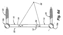
次に図6a〜図6fを参照すると、本発明の更に別の実施形態では、動的固定器具50が、内部中空領域24を備えた幾何学的形状部12を有し、この器具50は、幾何学的形状部12の平らな表面52に対して横の方向に曲がる。内部中空領域24は、好ましくは、傾斜した内面54を備えている。即ち、傾斜側壁56が、幾何学的形状部12の平坦面52と角度θをなした内面54を有している。内面54の角度θは、1つの一定の値であっても良く、器具内で変化しても良い。非限定的な例として、θは、器具50の頂部では60°であるのが良く、器具50の底部では約90°まで変化するのが良い。
6a-6f, in yet another embodiment of the present invention, a
次に図6a〜図6cを参照すると、内部中空領域24は、好ましくは、4つの部分的に円形のコーナー部又は先細セグメント26を有している。第1のロッド端部14及び第2のロッド端部16が、2つの向かい合った部分的に円形のコーナー部又は先細セグメント26に取り付けられている。各ロッド端部14,16が、幾何学的形状部12の各隣接側部から約135°の角度をなして位置している。しかしながら、この実施形態の別の特徴では、ロッド端部14,16は、幾何学的形状部12のアームに対して異なる角度で位置しても良い。器具10の場合と同様、部分的に円形のコーナー部又は先細セグメント26は、異なる形状部、例えば部分的に三角形のものであっても良い。均等例として、エラストマーヒンジ以外の機械的ヒンジを先細セグメント26のところに組み込んでも良い。
Referring now to FIGS. 6 a-6 c, the interior
図6dに示すように、椎弓根ねじ20は、幾何学的形状部12の平坦面52に垂直に差し向けられている。コネクタ18a,18bが、椎弓根ねじ20を動的固定器具50の第1のロッド端部14及び第2のロッド端部16に取り付けるために用いられている。当業者に知られているように、コネクタ18a,18bは、動的固定器具50の一体部分として形成されても良く、或いは、コネクタ18a,18bは、別個の部品であっても良い。使用にあたり、動的固定器具50は、屈曲を生じる2つの椎骨に取り付けられると、回転すると共に(或いは)曲がりながら拡張する。
As shown in FIG. 6 d, the
次に図7a〜図7cを参照すると、更に別の実施形態としての動的固定器具が示されている。動的固定器具58は、4つの実質的に真っ直ぐで且つ剛性のアームセグメントを有している。これらアームセグメントは、下側アーム60aと、第1の中間アーム60bと、第2の中間アーム60cと、上側アーム60dとから成っている。下側アーム60a及び上側アーム60dは、それぞれ、コネクタ18a,18bに連結され、これらコネクタが、この場合、椎弓根ねじ20に連結されている。ピン46により、下側アーム60aは、中間アーム60b,60cの一端部にヒンジ的に連結されている。上側アーム60dは、ピン46により中間アーム60b,60cの反対側の端部にヒンジ式に連結されている。4つのヒンジ箇所相互間には、四辺形の開口部24が形成されている。屈曲中、上側アーム60dは、上方且つ前方に動き、それにより中間アーム60b,60cを下方に回転させる。かくして、上側アーム60dへの中間アーム60b,60cのヒンジ式連結により、上側アーム60dは、前方に動くことができ、これに対し、下方アーム60aへの中間アーム60b,60cの連結により、過剰の並進又は過剰の回転が阻止されるようになっている。動的固定器具58は、上側椎骨が上方且つ前方に動くのを許容するが、動的固定器具58が取り付けられている椎骨の過剰の並進に抵抗する。
Referring now to FIGS. 7a-7c, yet another embodiment of a dynamic fixation device is shown. The
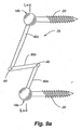
次に図8aを参照すると、更に別の実施形態としての動的固定器具が示されている。図8aに示された動的固定器具62は、前後方向セグメント64を有することを特徴とする動的固定器具である。動的固定器具62は、前後方向セグメント64に向かって角度αをなして延びるロッドアーム65を備えた第1のロッド端部14を有している。角度αは、ロッドアーム65と下側椎弓根ねじ20との剛性連結により、椎弓根ねじ20に対して固定されている。同様に、ロッドアーム73が、上側椎弓根ねじ20への剛性連結により固定されている。第1のロッド端部14のロッドアーム65は、曲がり部66のところで前後方向セグメント64に連結されている。具体的に説明すると、ロッドアーム65と前後方向セグメント64との間の連結部を形成する曲がり部66は、ロッドアーム65及び前後方向セグメント64が本質的に、曲がり部66を含む連続した中実部品であるように連続した構造的部品であるのが良い。変形例として、曲がり部66は、ロッドアーム65を前後方向セグメント64に連結するピンとヒンジ式連結状態にあっても良い。前後方向セグメント64は、角度βだけロッドアーム65から離されている。
Referring now to FIG. 8a, another embodiment of a dynamic fixation device is shown. The
依然として図8aを参照すると、曲がり部66のところでは、前後方向セグメント64は、曲がり部68まで後方に延びている。中間ロッドセグメント70が、前後方向セグメント64の後方端部のところの曲がり部68から第2のロッド端部16のロッドアーム73への連結部を形成する曲がり部72まで延びている。曲がり部72は、中間ロッドセグメント70とロッドアーム73との間の交差部であり且つ連結部を形成している。曲がり部72は、中間ロッドセグメント70及びロッドアーム73が曲がり部72を含む本質的に連続した中実部品であるように連続した構造的部品であっても良く、曲がり部72は、中間ロッドセグメント70とロッドアーム73を相互に連結する連結部であっても良い。中間ロッドセグメント70は、角度φだけ前後方向セグメント64から離されている。
Still referring to FIG. 8 a, at the
第1のロッド端部14及び第2のロッド端部16は、好ましくは、それぞれコネクタ18a,18bを用いて椎弓根ねじ20に連結されている。当業者には知られているように、コネクタ18a,18bは、動的固定器具62の端部の一体部分として形成されても良く、或いは、別個の部品であっても良い。
依然として図8aに示すこの実施形態の例を参照すると、動的固定器具62も又、コネクタ18a,18bの中心によって定められる長手方向軸線L−Lを有している。ロッドアーム65は、全体として、長手方向軸線L−Lの前方に位置し、中間ロッドセグメント70は、全体として、長手方向軸線L−Lの後方に位置し、前後方向セグメント64は、長手方向軸線L−Lの前側と後方側の両方に位置する部分を有している。
The
Still referring to the example of this embodiment shown in FIG. 8a, the
動的固定器具62が取り付けられている椎骨を圧縮状態に置いた場合に曲がり部68が、好ましくは、ヒンジとして働き、下方に動くことができるということがこの実施形態の特徴である。加うるに、曲がり部68は、椎骨の屈曲を許容するよう上方に動くことができる。曲がり部68及び前後方向セグメント64のこの動きは、ヒトの椎骨の通常の弧状運動に酷似している。圧縮時には、曲がり部68は、下方弧状経路74に沿って下方に動く。下方弧状経路74は、動的固定器具62を圧縮状態に置き、前後方向セグメント64がロッドアーム65に向かって動くときに生じ、それにより角度βを減少させる。典型的な患者としてのヒトでは、角度βは、曲がり部68が下方弧状経路74に沿って進むにつれて30°まで減少する場合がある。この動きを達成するため、動的固定器具62の曲がり部68は、好ましくは、これがヒンジとして働くことができるようにする構造を有する。したがって、曲がり部68は、ピン75を含むのが良い。図8aに示すように、ピン75は、中立位置で示されている。しかしながら、圧縮位置では、ピン75′は、その下方位置で示されている。椎骨が屈曲を行うと、曲がり部68は、上方弧状経路76に沿って上方に動く。上方弧状経路76は、動的固定器具62が伸長すると共に前後方向セグメント64が上方に動くときに生じ、それにより角度βを増大させる。少なくとも何人かの患者のでは、角度βは、曲がり部68が上方弧状経路76に沿って進むにつれて30°まで増大する場合がある。少なくとも何人かの患者の場合、前後方向セグメント64の中立位置は、曲がり部68が曲がり部66よりも下に位置した状態で水平から下方へ傾けられるであろう。かくして、角度βは、屈曲による伸長と比較して許容可能な圧縮量が少ない場合がある。伸長状態では、ピン75″は、その上方位置で示されている。圧縮の際、角度φは、減少し、動的固定器具が屈曲中に伸長すると、角度φは、増大することになる。
It is a feature of this embodiment that the bend 68 preferably acts as a hinge and can move downward when the vertebrae to which the
本発明の種々の実施形態は、椎骨の僅かな量の並進運動を可能にするが、並進運動の許容量は、ヒトの椎骨の通常の動作の生理学的限度の範囲内にある。例えば、図8aに示す実施形態の場合、ピン75が下方弧状経路74及び上方弧状経路76に沿って前方に動くと、椎骨は、ピン75′,75″の位置が中立位置から僅かに前方又は前進方向に動かされることによって明らかなように、僅かな量の並進運動を行うことになる。
次に図9a〜図9cを参照すると、更に別の実施形態としての動的固定器具が示されている。動的固定器具78は、3つの実質的に真っ直ぐなアームセグメントを有している。これらは、下方アーム80aと、第1の中間アーム80bと上方アーム80cとから成っている。下側アーム80a及び上側アーム80dは、それぞれ、コネクタ18a,18bに連結され、これらコネクタが、この場合、椎弓根ねじ20に連結されている。中間アーム80bの反対側の端部は、上方アーム80cにヒンジ式に連結されている(例えばピン46によって)。屈曲中、上側アーム80cは、上方且つ前方に動き、それにより中間アーム80bを下方に回転させる。かくして、上側アーム80cへの中間アーム80bのヒンジ式連結により、上側アーム80cは、前方回転を伴って上方に動くことができ、これに対し、中間アーム80bと下側アーム80aの連結により、過剰の並進又は過剰の回転が阻止されるようになっている。器具62の前後方向セグメント64の機能と同様に、この実施形態における中間アーム80bは、所与の範囲の屈曲運動を可能にするが、椎骨が過剰の並進を行うのを阻止する前後方向セグメントとして働く。かくして、動的固定器具78は、上側椎骨が上方に且つ僅かに前方に動くのを許容するが、動的固定器具78が取り付けられている椎骨の過剰の並進に抵抗する。
While various embodiments of the present invention allow for a small amount of translation of the vertebra, the translational tolerance is within the physiological limits of normal motion of the human vertebra. For example, in the embodiment shown in FIG. 8a, as the
Referring now to FIGS. 9a-9c, yet another embodiment of a dynamic fixation device is shown. The
次に、図10aを参照すると、更に別の実施形態としての動的固定器具が示されている。動的固定器具82は、第1のロッド端部14に連結された第1のロッド部材84及び第2のロッド端部16に連結された第2のロッド部材86を有し、第1のロッド端部14及び第2のロッド端部16は、それぞれ、コネクタ18a,18bを用いて椎弓根ねじ20に連結されている。第1のロッド部材84及び第2のロッド部材86は、バネ88を前後方向に閉じ込めている。加うるに、レール90が、バネ88の横方向側部を閉じ込めており、レール90は又、第1のロッド部材84を第2のロッド部材86に連結するのに役立つ。動的固定器具82の構造は、伸長することもでき、かくして屈曲を起こした場合の2つの隣り合う椎骨の自然な生理学的運動を許容する関節式器具を提供する。これらコンポーネントの構造及び機能について以下に詳細に説明する。
Referring now to FIG. 10a, yet another embodiment of a dynamic fixation device is shown. The
さらに図10aを参照すると、第1のロッド部材84は、好ましくは、その後方側部に沿って設けられた凹面92を有し、第1のロッド部材84の凹面92は、ばね88の前方閉じ込めを可能にするのを助けている。第2のロッド部材86は、好ましくは、その前側側部に沿って設けられた凹面94を有し、第2のロッド部材86の凹面94は、ばね88の後方閉じ込めを可能にするのを助けている。
Still referring to FIG. 10 a, the
上述したように、レール90(破線で示されている)は、第1のロッド部材84を第2のロッド部材86に連結している。好ましくは、レール90は、プレート96を有し、このプレート96の両端部を貫通してヒンジピン46が設けられている。プレート96は、図10bに示されている。好ましい一実施形態では、第1のロッド部材84は、第1のヒンジピン46を受け入れる第1の切欠き98を有している。同様に、第2のロッド部材86は、第2のヒンジピン46を受け入れる第2の切欠き98を有している。プレート96は、ばね88の閉じ込めゾーン100をまたいでおり、これらプレートは、第1のロッド部材84と第2のロッド部材86を互いに連結する一方で、ばね88をロッド部材84,86相互間に横方向に収納すると共にばね88が閉じ込めゾーン100の外部に動くのを阻止する。この実施形態の別の特徴では、レール90は、単一の部品を用いて形成されるのが良い。即ち、プレート96とヒンジピン46から成る構造を機械加工し又は違ったやり方で単一の部品で構成するのが良い。
As described above, the rail 90 (shown in broken lines) connects the
一例を挙げると、好ましくはばね88は、動的固定器具82について適正なばね定数を有する円筒形のばねであるが、これには限られない。加うるに、ばね88は、例えば円板又は球として形作られた例えば適当なサイズのシリコーンインサートである弾性材料の形態をしていても良い。脊椎の屈曲運動中、第2のロッド部材86は、上方且つ前方に動く。この運動中、ばね88は、第1のロッド部材84と第2のロッド部材86との間で丸まる。ばね88が丸まるので、第1のロッド部材84と第2のロッド部材86との間の摩擦は、最小限に抑えられる。かくして、ばねの丸まる能力は、ばねの形状並びに閉じ込めゾーン100の内壁の形状及びテクスチャを調節することにより改変可能である。具体的に説明すると、第1及び第2のロッド部材84,86のそれぞれの凹面92,94の形状及び表面テクスチャを改変すると、第1のロッド部材84に対する第2のロッド部材86の伸長の大きさ及び伸長の際の運動のしやすさを調節することができる。ばね88は、圧縮可能なので、ばねは、変形し、それにより曲げを可能にする。圧縮量は、ばねの特徴、例えばばねの材料の種類、直径及び肉厚並びに閉じ込めゾーン100の形状及び凹面92,94のテクスチャによって制御される。閉じ込めゾーン100の形状に関し、凹面92,94は、ばね88の閉じ込めゾーン100の圧縮面としての役目を果たす。凹面92,94の曲線の形状を変更すると、この構造体が伸長するときのばねの圧縮度を制御することができる。例えば、図10aを参照すると、凹面92,94の曲率を平べったくすることができ、それにより、屈曲伸長中における閉じ込めゾーン100内でのばね88の反応に影響を及ぼすことができる。
In one example, the
次に図10c及び図10dを参照すると、動的固定器具82が、それぞれその中立位置とその屈曲位置との両方で示されている。分かりやすくする目的で、レール90は、図10c及び図10dにおいて破線で示されている。図10cに示す中立位置と比較して、図10dの伸長位置は、ばね88が巻き上がり、又僅かに圧縮されていることを示している。ばね88の特性は、ばねの或る程度の所望の圧縮量が、屈曲中許容されるが、ばね88が椎骨の望ましくない並進量に抵抗するのに十分剛性であるように選択される。
Referring now to FIGS. 10c and 10d, the
動的固定器具82は、第2のロッド部材86が第1のロッド部材84にヒンジ式に取り付けられているので伸長するようになり、それにより第1のロッド部材84に対する第2のロッド部材86の垂直運動が可能になる。かくして、動的固定器具82の構造は、伸長でき、かくして脊椎の自然な生理学的運動を許容する関節式器具を提供する。
動的固定器具82は、脊椎の部分的に適用される運動制御の提供に利用される。というのは、インプラントを受け入れるよう設計された各運動セグメントは、その寸法及びばね定数を介してカスタマイズされた動的固定器具インプラントを有することができ、それにより患者に所望される通常の生理学的範囲内の制御された動きを与えることができるからである。
The
The
2つの椎骨を跨ぐための代表的な使用法では、動的固定器具10,34,34′,50,58,62,78,82の全長は、約15〜35mmであるのが良い。動的固定器具の幾何学的形状部分又はヒンジ構造体は、好ましくは、2つの椎骨を橋渡しするインプラントの中央領域を占める。即ち、幾何学的形状部又はヒンジ構造体は、インプラントの一部分しか占めず、それにより第1のロッド端部14及び第2のロッド端部16が、コネクタ器具を用いて椎弓根ねじに連結できる中実ロッドセグメントであることができるようにする。幾何学的形状部及びヒンジ式構造体を有する器具の場合、これら構造体は、代表的には、約15〜20mmの全長を占めることになる。
In a typical use for straddling two vertebrae, the overall length of the
次に図11a〜図11dを参照すると、本発明の実施形態としての動的固定器具102が示されている。この器具は、脊椎に対して横断方向に且つ(或いは)実質的に脊椎に対して前後方向の向きに整列した異形の形状部又は輪郭形状部106を含む前後方向セグメント104を有している。前後方向セグメント104は、一方の方向(屈曲)の方が他方の方向(伸長)よりも比較的容易に曲がることができる。加うるに、前後方向セグメント104は、セグメントの平面内における運動に抵抗し、これは、並進運動の抵抗に相当している。かくして、動的固定器具102は、屈曲の際に少なくとも或る程度の椎骨の回転を許容すると共に椎骨の並進に抵抗する。
Referring now to FIGS. 11a-11d, a
前後方向セグメント104は、約20mmの前後方向寸法及び約10mmの横方向幅を有するのが良いが、前後方向セグメントの寸法は、所望の移動量、インプラントの被移植者としての患者の体格並びに器具を構成するために用いられる寸法及び材料の種類を含む多くの要因に応じて様々であることが予想される。本発明の実施形態によれば、動的固定器具102は、屈曲の際に約10°オーダーの回転をもたらし、伸長の際に約−2°のオーダーの回転をもたらす。
The
次に図11aを参照すると、輪郭形状部106を含む前後方向セグメント104を備えた動的固定器具102が全体的に示されている。輪郭形状部106により、動的固定器具102は、器具102が屈曲の際に伸長すると、事実上のピボット箇所32回りに回転することができる。動的固定器具102は、第1のロッド端部14に連結され又はこれと一体の第1のロッド部材108と、第2のロッド端部16に連結され又はこれと一体の第2のロッド部材110とを有し、第1のロッド端部14と第2のロッド端部16は、それぞれ、コネクタ18a,18bを用いて椎弓根ねじ20に連結されている。第1のロッド部材108及び第2のロッド部材110は、前後方向セグメント104に前後方向に取り付けられ又はこれと一体である。本発明の少なくとも1つの実施形態によれば、前後方向セグメント104とロッド部材108,110との間の取り付け部、相互連結部又は接合部分は、撓み連結部、例えば一体ヒンジ又はピン止め連結部から成るのが良い。
Referring now to FIG. 11a, a
動的固定器具102の少なくとも幾つかの部分は、医学的用途に用いられたときに人体からの加重に耐えるのに必要な適当な強度特性を備えた1種類又は2種類以上の材料で作られるのが良い。加うるに、かかる材料は、所望の可撓性を提供するよう選択されるのが良い。本発明の実施形態によれば、動的固定器具102の少なくとも幾つかの部分を構成するために使用できる材料の例としては、ポリエチレンエーテルプラスチック、例えばケトン(PEEK)、ポリエーテルケトンケトン(PEKK)、超高分子量ポリエチレン(UHMWPE)及びポリメチルメタクリレート(PMMA)、金属、例えばチタン及びステンレス鋼、複合材並びに他の組織適合性材料が挙げられるが、必ずしもこれらには限定されない。
At least some portions of the
依然として図11aに示す本発明の例を参照すると、動的固定器具102は又、コネクタ18a,18bの中心によって定められた長手方向軸線L−Lを有している。ロッド部材108は、全体として、長手方向軸線L−Lの前方に位置し、ロッド部材110は、全体として、実質的に長手方向軸線L−Lのところ又はその後方に位置する。本発明の少なくとも1つの実施形態によれば、前後方向セグメント104は、長手方向軸線L−Lの前側と後方側の両方に位置する部分を有する。加うるに、動的固定器具102が植え込まれるべき患者の体は、上方向及び下方向を定める。具体的に説明すると、上方又は患者の頭に向かう方向は、上方向と定義され、下方又は患者の足に向かう方向は、下方向と定義される。本発明の少なくとも1つの実施形態では、ロッド部材108は、下方向に差し向けられ、ロッド部材110は、上方向に差し向けられる。
Still referring to the example of the present invention shown in FIG. 11a, the
次に図11bを参照すると、前後方向セグメントの拡大図が示されている。本発明の少なくとも幾つかの実施形態によれば、前後方向セグメント104は、一方の方向における他方の方向に対する運動を可能にするのを助ける輪郭形状部106を有しており、輪郭は、例えば1つ又は2つ以上のディンプル112のような形状から成るのが良い。図11bに示す実施形態では、前後方向セグメント104は、第1のディンプル112aを有し、この第1のディンプルは、実質的に長手方向軸線L−Lの後方に又は少なくとも第2のディンプル112bの後方に位置する。加うるに、図11bに示す実施形態では、第2のディンプル112bは、実質的に長手方向軸線L−Lの前方に位置する。第1のディンプル112aは、凹面を有し、この凹面は、凹部が下方向に向くように差し向けられている。第2のディンプル112bは、凹面を有し、この凹面は、凹部が上方向に向くように差し向けられている。変形例として、前後方向セグメント104は、ディンプル112以外の形状部から成っていても良い。例えば、輪郭形状部106は、複数の向き、例えば上方向及び下方向に向いた凹面を備える楕円形特徴部を有しても良い。他の形状部の前後方向セグメント104も又、本発明の範囲に含まれる。ディンプル112を含む前後方向セグメント104は、所望量の曲げを可能にする材料で作られている。ディンプルを備えた輪郭形状部106は、別の方向ではなく、優先的に一方向に優先的に生じる特定の箇所における曲げを可能にする。特に、ディンプル112は、曲線に向かう曲げに対する抵抗が低く、曲線から離れる曲げに対する抵抗が高い。
Referring now to FIG. 11b, an enlarged view of the anteroposterior segment is shown. According to at least some embodiments of the present invention, the
図11c及び図11dに記載された例で示すように、第1のロッド端部14は、本質的に動かないままであるものとして示されている。第2のロッド端部16は、図11bに示す中立位置又は第1の位置114と図11dに示す屈曲位置又は第2の位置116との間で動く。動的固定器具102は、第1の位置114と第2の位置116との間で動く際、細長くなり又は伸長を許容し、又、この動的固定器具102は、生理学的回転ゾーン又は事実上のピボット箇所32回りに回転する。かくして、輪郭形状部106は、長手方向軸線L−Lの前方又は前進方向に位置する事実上のピボット箇所32を備える。動的固定器具102は、第1の位置114と第2の位置116との間における運動中、変形を生じ、それにより動的固定器具は、曲がり、そして、この器具102が取り付けられている椎骨の屈曲の際の少なくとも或る程度の動きを許容するよう伸長する。事実上のピボット箇所32は、脊椎の屈曲と伸展の両方の間における輪郭形状部106の運動状態を含む器具102の幾何学的形状によって提供される。図11に示す脊椎の運動は、ディンプル112bの曲率に向かい、ディンプル112aの曲率から離れる。したがって、ディンプル112bは、この動きに対して生じる抵抗が小さく、ディンプル112aは、この動きに対して生じる抵抗が高い。輪郭形状部106のこの応答により、ほぼ前後方向セグメント104の中心のところに位置する箇所が、ほぼ図11aに示す経路113に沿って移動すると共に事実上のピボット箇所32回りに回転することができる。これと同様な運動が、脊椎の伸展中に生じ、動的固定器具102は、僅かに圧縮状態になる。この動きの方向は、ディンプル112bの曲率から離れ、ディンプル112aの曲率に向かう方向である。したがって、ディンプル112bは、この動きに対して生じる抵抗が高く、ディンプル112aは、この動きに対して生じる抵抗が低い。前後方向セグメント104のこの動きにより、動的固定器具102は、ヒトの椎骨の通常の生理学的運動に酷似した仕方で動くことができる。
As shown in the example described in FIGS. 11c and 11d, the
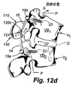
次に図12a〜図12dを参照すると、本発明の実施形態としての動的固定器具118が示されている。この器具は、可撓性ロッド部材120,121及び脊椎に対して横断方向に且つ(或いは)実質的に脊椎に対して前後方向の向きに整列した前後方向セグメント124を有している。動的固定器具は118は、一方の方向(屈曲)の方が他方の方向(伸長)よりも比較的容易に曲がることができる。加うるに、動的固定器具118は、セグメントの平面内における運動に抵抗し、これは、並進運動の抵抗に相当している。かくして、動的固定器具118は、屈曲の際に少なくとも或る程度の椎骨の回転を許容すると共に椎骨の並進に抵抗する。
Referring now to FIGS. 12a-12d, a
前後方向セグメント124は、約20mmの前後方向寸法及び約10mmの横方向幅を有するのが良いが、前後方向セグメントの寸法は、所望の移動量、インプラントの被移植者としての患者の体格並びに器具を構成するために用いられる寸法及び材料の種類を含む多くの要因に応じて様々であることが予想される。本発明の実施形態によれば、動的固定器具116は、屈曲の際に約10°オーダーの回転をもたらし、伸長の際に約−2°のオーダーの回転をもたらす。
The
次に図12aを参照すると、第1の可撓性ロッド部材120、第2の可撓性ロッド部材122及び前後方向セグメント124を備えた動的固定器具118が、全体的に示されている。可撓性ロッド部材120,122により、動的固定器具118は、器具118が屈曲の際に伸長すると、事実上のピボット箇所32回りに回転することができる。第1の可撓性ロッド部材120は、第1のロッド端部14に連結され、この第1のロッド端部は、コネクタ18aにより椎弓根ねじ20に連結されている。第2の可撓性ロッド部材122は、第2のロッド端部16に連結され、この第2のロッド端部は、コネクタ18bにより椎弓根ねじ20に連結されている。第1のロッド部材120及び第2のロッド部材122は、前後方向セグメント124に前後方向に取り付けられ又はこれと一体である。本発明の少なくとも1つの実施形態によれば、前後方向セグメント124とロッド部材120,122との間の取り付け部、相互連結部又は接合部分は、撓み連結部、例えば一体ヒンジ又はピン止め連結部から成るのが良い。
Referring now to FIG. 12a, a
動的固定器具118の少なくとも幾つかの部分は、医学的用途に用いられたときに人体からの加重に耐えるのに必要な適当な強度特性を備えた1種類又は2種類以上の材料で作られるのが良い。加うるに、かかる材料は、所望の可撓性を提供するよう選択されるのが良い。本発明の実施形態によれば、動的固定器具118の少なくとも幾つかの部分を構成するために使用できる材料の例としては、ポリエチレンエーテルプラスチック、例えばケトン(PEEK)、ポリエーテルケトンケトン(PEKK)、超高分子量ポリエチレン(UHMWPE)及びポリメチルメタクリレート(PMMA)、金属、例えばチタン及びステンレス鋼、複合材並びに他の組織適合性材料が挙げられるが、必ずしもこれらには限定されない。
At least some portions of the
依然として図12aに示す本発明の例を参照すると、動的固定器具118は又、コネクタ18a,18bの中心によって定められた長手方向軸線L−Lを有している。ロッド部材120は、全体として、長手方向軸線L−Lの前方に位置し、ロッド部材122は、全体として、実質的に長手方向軸線L−Lのところ又はその後方に位置する。本発明の少なくとも1つの実施形態によれば、前後方向セグメント124は、長手方向軸線L−Lの前側と後方側の両方に位置する部分を有する。
Still referring to the example of the invention shown in FIG. 12a, the
可撓性ロッド部材120,122は、これらロッド部材が曲がることができるようにする継手を備えている。図12aは、ロッド部材120の継手126a及びロッド部材122の継手126bを示している。継手の機能をより明確に説明するために、以下ロッド部材120の継手126aについて説明する。理解できるように、ロッド部材122の継手126bは、これと同様に機能する。継手126aは、下側可撓性ロッド部分120aと上側可撓性ロッド部分120bを互いに連結している。継手126aは、角度λにわたる可撓性ロッド部材120の曲げを可能にし、この角度λは、上可撓性ロッド部分120aと前後方向セグメント124とのなす角度である。同様に、角度μは、継手126bの運動範囲を定めている。
The
図12bは、可撓性ロッド部材120の継手126aの詳細図である。本発明の少なくとも一実施形態によれば、継手126aは、2つのセグメント130により軸方向に境界付けられたセグメント128で構成されている。セグメント130は、一連の凹み部分132から成る。本発明の少なくとも一実施形態によれば、凹み部分132は、ロッド部材120の前側側部かロッド部材120の後側側部かのいずれかに対して差し向けられている。かくして、改造型セグメント130は、後方に差し向けられた凹み部分132aと前方に差し向けられた凹み部分132bが交互に位置する一連の凹み部分132から成る。凹み部分132を当該技術分野において知られている技術、例えば材料を除去すること、切れ目をロッドに入れること又は射出成形により凹み部分132を形成することにより作ることができる。加うるに、継手126a,126bのところに可撓性をもたらす他の構造、例えば薄肉部分、三日月形セグメント等は、本発明の範囲に含まれる。
FIG. 12 b is a detailed view of the joint 126 a of the
図12c及び図12dに記載された例に示すように、第1のロッド端部14は、本質的に動かないままであるものとして示されている。第2のロッド端部16は、図12cに示す中立位置又は第1の位置134と図12dに示す屈曲位置又は第2の位置136との間で動く。動的固定器具118は、第1の位置134と第2の位置136との間で動く際、伸長し、又、この動的固定器具118は、生理学的回転ゾーン又は事実上のピボット箇所32回りに回転する。1つ又は2つ以上の継手126a,126bを備えた可撓性ロッド部材120,122は、前後方向セグメント124と一緒になって、長手方向軸線L−Lの前進方向又は前方に位置する事実上のピボット箇所32を構成する。動的固定器具118は、第1の位置134と第2の位置136との間における運動中、変形を生じ、それにより動的固定器具は、曲がり、そして、この器具118が取り付けられている椎骨の屈曲の際の少なくとも或る程度の動きを許容するよう伸長する。事実上のピボット箇所32は、継手126a,126bの曲げ状態を含む器具118の幾何学的形状により提供される。動的固定器具118が伸長すると、継手126aは、角度λが増大するよう曲がる。同様に、継手126bは、角度μが増大するよう曲がる。これにより、動的固定器具は、図12dに示すように曲がることができる。継手126a,126bが曲がると、動的固定器具118は、事実上のピボット箇所32回りに回転するようになる。この動きにより、動的固定器具118は、ヒトの椎骨の通常の動きに酷似した仕方で動くことができる。
As shown in the example described in FIGS. 12c and 12d, the
次に図13a〜図13dを参照すると、本発明の実施形態としての動的固定器具136が示されている。この器具は、部分的に折り畳まれたロッドセグメント138を有している。部分的折り畳みセグメント138は、一方の方向(屈曲)の方が他方の方向(伸長)よりも比較的容易に曲がることができる。加うるに、部分的折り畳みセグメント138は、セグメントの平面内における運動に抵抗し、これは、並進運動の抵抗に相当している。かくして、動的固定器具136は、屈曲の際に少なくとも或る程度の椎骨の回転を許容すると共に椎骨の並進に抵抗する。
Referring now to FIGS. 13a-13d, a
部分的折り畳みセグメント138は、約20mmの前後方向寸法を有するのが良いが、部分的折畳みセグメントの寸法は、所望の移動量、インプラントの被移植者としての患者の体格並びに器具を構成するために用いられる寸法及び材料の種類を含む多くの要因に応じて様々であることが予想される。本発明の実施形態によれば、動的固定器具136は、屈曲の際に約10°オーダーの回転をもたらし、伸長の際に約−2°のオーダーの回転をもたらす。
The partially folded
次に図13aを参照すると、部分的折り畳みセグメント138を備えた動的固定器具136が、全体として示されている。部分的折り畳みセグメント138により、動的固定器具136は、器具136が屈曲の際に伸長すると、事実上のピボット箇所32回りに回転することができる。この折り畳みセグメントは、第1のロッド端部14及び第2のロッド端部16に取り付けられている。第1のロッド端部14及び第2のロッド端部16は、それぞれ、コネクタ18a,18bによって椎弓根ねじ20に連結されている。動的固定器具136は又、コネクタ18a,18bの中心により定められた長手方向軸線L−Lを有している。
Referring now to FIG. 13a, a
動的固定器具136の少なくとも幾つかの部分は、医学的用途に用いられたときに人体からの加重に耐えるのに必要な適当な強度特性を備えた1種類又は2種類以上の材料で作られるのが良い。加うるに、かかる材料は、所望の可撓性を提供するよう選択されるのが良い。本発明の実施形態によれば、動的固定器具136の少なくとも幾つかの部分を構成するために使用できる材料の例としては、ポリエチレンエーテルプラスチック、例えばケトン(PEEK)、ポリエーテルケトンケトン(PEKK)、超高分子量ポリエチレン(UHMWPE)及びポリメチルメタクリレート(PMMA)、金属、例えばチタン及びステンレス鋼、複合材並びに他の組織適合性材料が挙げられるが、必ずしもこれらには限定されない。
At least some portions of the
依然として図13aに示すこの実施形態の例を参照すると、部分的折り畳みセグメント138は、一連の実質的に平らなセグメント140から成っている。部分的折り畳みセグメント138は、相互に連結された要素で作られるのが良く、或いは、変形例として、単一の材料片から機械加工により形成しても良い。可撓性継手、例えば一体ヒンジ141が、隣り合う平らなセグメント140を互いに連結している。本発明の少なくとも幾つかの実施形態によれば、平らなセグメント140は、四辺形の形をしている。各平らなセグメントは、実質的に前後方向に差し向けられた2つの側部142a,142b及び実質的に上下方向に差し向けられた2つの側部144a,144bを有している。本発明の少なくとも幾つかの実施形態によれば、長手方向軸線L−Lの後方に位置する側部144aの長さは、長手方向軸線L−Lの前方に位置する側部144bの長さよりも長い。長さのこの差により、折り畳みセグメント138は、うちわと似た仕方で広がることができる。図13bは、後方から前方の方向に見た折り畳みセグメント138の拡大図である。
Still referring to the example of this embodiment shown in FIG. 13 a, the partially folded
図13c及び図13dに記載された例で示すように、第1のロッド端部14は、本質的に動かないままであるものとして示されている。第2のロッド端部16は、図13cに示す中立位置又は第1の位置146と図13dに示す屈曲位置又は第2の位置148との間で動く。動的固定器具136は、第1の位置146と第2の位置148との間で動く際、伸長し又は伸長を許容し、又、この動的固定器具136は、生理学的回転ゾーン又は事実上のピボット箇所32回りに回転する。かくして、部分的折畳みセグメント138は、長手方向軸線L−Lの前進方向又は前方に位置する事実上のピボット箇所32を構成する。動的固定器具136は、第1の位置146と第2の位置148との間における運動中、変形を生じ、それにより動的固定器具は、曲がり、そして、この器具136が取り付けられている椎骨の屈曲の際の少なくとも或る程度の動きを許容するよう伸長する。
As shown in the example described in FIGS. 13c and 13d, the
折り畳みセグメント138により、動的固定器具136は、伸長すると共に事実上のピボット箇所32回りに回転することができる。図13a及び図13bに示すように、平らなセグメント140は、全て脊椎に向かう方向に傾けられている。具体的に言えば、平らなセグメント140は、全て動的固定器具136の前方に位置する1点のところに収斂する線上に差し向けられている。この点は、動的固定器具136の事実上のピボット箇所のおおよその存在場所を提供する。動的固定器具136が伸長すると、折り畳みセグメント138は、広がって、事実上のピボット箇所32回りの回転を可能にする。これにより、動的固定器具は、図13dに示すように曲がることができる。この動きにより、動的固定器具118は、屈曲時におけるヒトの椎骨の通常の動きに酷似した仕方で動くことができ、しかも生理学的に異常な量の並進運動に抵抗することができる。
The
次に図14a〜図14dを参照すると、本発明の実施形態としての動的固定器具150が示されている。この器具は、部分的折り畳みロッドセグメント152を有している。部分的折り畳みセグメント152は、一方の方向(屈曲)の方が他方の方向(伸長)よりも比較的容易に曲がることができる。加うるに、部分的折り畳みセグメント152は、セグメントの平面内における運動に抵抗し、これは、並進運動の抵抗に相当している。かくして、動的固定器具150は、屈曲の際に少なくとも或る程度の椎骨の回転を許容すると共に椎骨の並進に抵抗する。
Referring now to FIGS. 14a-14d, a
部分的折り畳みセグメント152は、約20mmの前後方向寸法を有するのが良いが、部分的折畳みセグメントの寸法は、所望の移動量、インプラントの被移植者としての患者の体格並びに器具を構成するために用いられる寸法及び材料の種類を含む多くの要因に応じて様々であることが予想される。本発明の実施形態によれば、動的固定器具150は、屈曲の際に約10°オーダーの回転をもたらし、伸長の際に約−2°のオーダーの回転をもたらす。
The partially folded
次に図14aを参照すると、部分的折り畳みセグメント152を備えた動的固定器具150が、全体として示されている。部分的折り畳みセグメント152により、動的固定器具150は、器具150が屈曲の際に伸長すると、事実上のピボット箇所32回りに回転することができる。この部分的折り畳みセグメント152は、第1のロッド端部14及び第2のロッド端部16に取り付けられている。第1のロッド端部14及び第2のロッド端部16は、それぞれ、コネクタ18a,18bによって椎弓根ねじ20に連結されている。
Referring now to FIG. 14a, a
動的固定器具150の少なくとも幾つかの部分は、医学的用途に用いられたときに人体からの加重に耐えるのに必要な適当な強度特性を備えた1種類又は2種類以上の材料で作られるのが良い。加うるに、かかる材料は、所望の可撓性を提供するよう選択されるのが良い。本発明の実施形態によれば、動的固定器具150の少なくとも幾つかの部分を構成するために使用できる材料の例としては、ポリエチレンエーテルプラスチック、例えばケトン(PEEK)、ポリエーテルケトンケトン(PEKK)、超高分子量ポリエチレン(UHMWPE)及びポリメチルメタクリレート(PMMA)、金属、例えばチタン及びステンレス鋼、複合材並びに他の組織適合性材料が挙げられるが、必ずしもこれらには限定されない。
At least some portions of the
部分的折り畳みセグメント152は、一連の実質的に平らなセグメント154から成っている。部分的折り畳みセグメント152は、相互に連結された要素で作られるのが良く、或いは、変形例として、単一の材料片から機械加工により形成しても良い。本発明の少なくとも幾つかの実施形態によれば、平らなセグメント154は、矩形の形をしている。各平らなセグメント154は、実質的に前後方向に差し向けられた2つの側部156a,156b及び実質的に上下方向に差し向けられた2つの側部158a,158bを有している。図14aに示すように、動的固定器具150も又、コネクタ18a,18bの中心によって定められる長手方向軸線L−Lを有している。本発明の少なくとも幾つかの実施形態によれば、長手方向軸線L−Lの後方に位置する側部158aの長さは、長手方向軸線L−Lの前方に位置する側部158bの長さよりも長い。平らなセグメント154の側部は、ほぼ同一の長さのものであるが、部分的折り畳みセグメント154が十分に弾性のある材料で作られている場合、部分的折り畳みセグメント154は、動的固定器具150の定点に順応することになる。図14bは、後方から前方の方向に見た折り畳みセグメント152の拡大図である。
Partially folded
図14c及び図14dに記載された例で示すように、第1のロッド端部14は、本質的に動かないままであるものとして示されている。第2のロッド端部16は、図14cに示す中立位置又は第1の位置160と図14dに示す屈曲位置又は第2の位置162との間で動く。動的固定器具150は、第1の位置160と第2の位置162との間で動く際、伸長し又は伸長を許容し、又、この動的固定器具150は、生理学的回転ゾーン又は事実上のピボット箇所32回りに回転する。部分的折畳みセグメント138は、長手方向軸線L−Lの前進方向又は前方に位置する事実上のピボット箇所32を構成する。動的固定器具150は、第1の位置160と第2の位置162との間における運動中、変形を生じ、それにより動的固定器具は、曲がり、そして、この器具150が取り付けられている椎骨の屈曲の際の少なくとも或る程度の動きを許容するよう伸長する。
As shown in the example described in FIGS. 14c and 14d, the
折り畳みセグメント152により、動的固定器具150は、伸長すると共に事実上のピボット箇所32回りに回転することができる。脊椎が図14cに示す中立位置から図14dに示す屈曲位置に動いているとき、動的固定器具150は、伸長を生じる。この伸長により、折り畳みセグメント150は、広がる。これにより、動的固定器具は、図14dに示すように曲がることができる。本発明の実施形態によれば、事実上のピボット箇所32回りの回転は、部分的折り畳みセグメントの平らなセグメント及び可撓性継手が、上述の運動を可能にするのに十分な強度及び可撓性の材料で作られていることに起因して生じる。かかる材料としては、PEEK及びPEKKが挙げられるが、これらには限定されない。この動きにより、動的固定器具150は、ヒトの椎骨の通常の動きに酷似した仕方で動くことができる。
The
次に図15a〜図15cを参照すると、本発明の実施形態としての動的固定器具170が図示されている。この器具は、ヒンジ174により互いに連結された複数個のセグメント172を有している。複数のヒンジ式セグメント172は、一方の方向(屈曲)の方が他方の方向(伸長)よりも比較的容易に曲がることができる。加うるに、複数のヒンジ式セグメント172は、セグメントの平面内における運動に抵抗し、これは、並進運動の抵抗に相当している。かくして、動的固定器具170は、屈曲の際に少なくとも或る程度の椎骨の回転を許容すると共に椎骨の並進に抵抗する。
Referring now to FIGS. 15a-15c, a
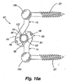
次に図15aを参照すると、複数個のヒンジ式セグメント172を備えた動的固定器具170が示されている。本発明の少なくとも一実施形態では、ヒンジ174は、動的固定器具170の前進方向又は前方方向に差し向けられたピン176を有する。ヒンジ174のピン176のこの向きにより、脊椎が屈曲を起こしたときに第1の椎骨の第2の椎骨に対する自然なピボット箇所に類似した前進方向又は前方に突き出されたピボット箇所32が得られる。動的固定器具170は、下ヒンジ式セグメント172a、上ヒンジ式セグメント172b及び内部ヒンジ式セグメント172cを有している。下ヒンジ式セグメント172a及び上ヒンジ式セグメント172bは各々、それぞれ、コネクタ18a,18bへのヒンジ式連結部を有している。内部ヒンジ式セグメント172cは、下ヒンジ式セグメント172aと上ヒンジ式セグメント172bとの間に配置されていて、これらへのヒンジ式連結部を有している。コネクタ18a,18bは各々、椎弓根ねじ20に取り付けられている。上ヒンジ式セグメント172bの両端部を互いに連結するヒンジ174は、これらの構造を示すために図15aでは互いに分離して示されている。
Referring now to FIG. 15a, a
動的固定器具170は、医学的用途に用いられたときに人体からの加重に耐えるのに必要な適当な強度特性を備えた1種類又は2種類以上の材料で作られるのが良い。加うるに、かかる材料は、所望の可撓性を提供するよう選択されるのが良い。本発明の実施形態によれば、動的固定器具170の少なくとも幾つかの部分を構成するために使用できる材料の例としては、ポリエチレンエーテルプラスチック、例えばケトン(PEEK)、ポリエーテルケトンケトン(PEKK)、超高分子量ポリエチレン(UHMWPE)及びポリメチルメタクリレート(PMMA)、金属、例えばチタン及びステンレス鋼、複合材並びに他の組織適合性材料が挙げられるが、必ずしもこれらには限定されない。
The
依然として図15aに示すこの実施形態の例を参照すると、動的固定器具170も又、コネクタ18a,18bの中心によって定められた長手方向軸線L−Lを有している。本発明の実施形態によれば、下ヒンジ式セグメント172a、上ヒンジ式セグメント172b及び内部ヒンジ式セグメント172cは、全体として、椎弓根ねじ20に垂直な平面内に且つ長手方向軸線L−Lに対して鋭角をなして位置している。
Still referring to the example of this embodiment shown in FIG. 15a, the
動的固定器具170の機能は、図15b及び図15cに示されている。図15bは、動的固定器具170を脊椎が屈曲されておらず伸延もされていない中立位置182で示している。コネクタ18aに連結された椎弓根ねじ20は、下側椎骨に取り付けられている。コネクタ18bに連結された椎弓根ねじ20は、上側椎骨に取り付けられている。図15cは、動的固定器具170を屈曲位置184で示している。動的固定器具170は、第1の位置182と第2の位置184との間で動く際、伸長し、又事実上のピボット箇所32回りに回転する。この屈曲運動中、複数個のヒンジ式セグメント172は、より上下方向に整列した状態で回転し、少なくともセグメント172a,172bが、長手方向軸線L−Lに関してますます平行に整列するようになり、それにより、動的固定器具170を長くすると共に上側椎骨が下側椎骨に対して前方に回転できるようにする。加うるに、かかる構造を形成するために用いられる比較的剛性の材料は、前後方向の運動に抵抗し、それにより2つの互いに連結された椎骨の並進運動に抵抗する。ヒンジ式セグメント172のこの運動により、動的固定器具170は、ヒトの椎骨の通常の生理学的運動に酷似した仕方で動くことができる。本発明の実施形態によれば、動的固定器具170は、屈曲の際に約10°オーダーの回転をもたらし、伸長の際に約−2°のオーダーの回転をもたらす。
The function of the
1つの継手を跨ぐ動的固定器具170の場合、動的固定器具170は、長さが約5〜10mmまで伸長すると共に5°〜10°まで前方に回転して脊椎の屈曲に順応する。明らかなこととして、種々のサイズの動的固定器具170を患者個人個人の特定の要望に応じて使用できる。具体的に説明すると、比較的大型の動的固定器具は、体格の大きな人に必要な場合があり、比較的小型の動的固定器具は、体格の小さな患者、例えば子供又は小柄の婦人に必要な場合がある。しかしながら、サイズの数が限られていても、これらのサイズは、患者人口の大部分を適当にカバーすることができる。任意所与の器具の場合、椎骨運動セグメントの所望の屈曲及びこれと関連した動的固定器具の平面の伸延と一致した動的固定器具の潜在的伸長が予想される。
In the case of a
本発明の実施形態によれば、本明細書において説明したヒンジは、ピンを備えなくても良い。具体的に説明すると、図3a、図4a、図5a、図6a、図7a、図8a、図9a、図11a、図12a、図13a及び図14aに示された本発明の実施形態は、可撓性要素、例えば一体ヒンジを有しても良い。
動的固定器具は、複数個の椎骨を屈曲可能に固定するために使用されるのが良い。変形例として、動的固定器具を脊椎の曲げが望ましい特定の箇所に配置することができる一方で、剛性ロッドを外科医の望む他の場所で使用することができる。使用時に剛性ロッド部分を湾曲させるのが良く、それにより幾何学的形状部のヒンジ式構造体の植え込み場所及びかくして事実上のピボット箇所に影響が及ぼされる。
According to embodiments of the present invention, the hinge described herein may not include a pin. Specifically, the embodiments of the present invention shown in FIGS. 3a, 4a, 5a, 6a, 7a, 8a, 9a, 11a, 12a, 13a and 14a are possible. It may have a flexible element, for example an integral hinge.
The dynamic fixation device may be used to flexibly fix a plurality of vertebrae. Alternatively, the dynamic fixation device can be placed in a specific location where spinal bending is desired, while the rigid rod can be used elsewhere as desired by the surgeon. In use, the rigid rod portion may be curved, thereby affecting the implantation location of the hinged structure of the geometry and thus the actual pivot location.
本発明の構造体は、医学的用途に用いられたときに人体からの加重に耐えるのに必要な適当な強度特性を備えた1種類又は2種類以上の材料で作られるのが良い。加うるに、これら材料は、人体と適合性がある。好ましくは、かかる材料としては、セラミック、プラスチック、金属又は炭素繊維複合材が挙げられる。好ましくは、これら材料は、チタン、チタン合金又はステンレス鋼で作られる。 The structure of the present invention may be made of one or more materials with the appropriate strength characteristics necessary to withstand the load from the human body when used in medical applications. In addition, these materials are compatible with the human body. Preferably, such materials include ceramics, plastics, metals or carbon fiber composites. Preferably, these materials are made of titanium, titanium alloy or stainless steel.
本発明の構造体は、医学的用途に用いられたときに人体からの加重に耐えるのに必要な適当な強度特性を備えた1種類又は2種類以上の材料で作られるのが良い。加うるに、これら材料は、人体と適合性がある。好ましくは、かかる材料としては、セラミック、プラスチック、金属又は炭素繊維複合材が挙げられる。好ましくは、これら材料は、チタン、チタン合金又はステンレス鋼で作られる。 The structure of the present invention may be made of one or more materials with the appropriate strength characteristics necessary to withstand the load from the human body when used in medical applications. In addition, these materials are compatible with the human body. Preferably, such materials include ceramics, plastics, metals or carbon fiber composites. Preferably, these materials are made of titanium, titanium alloy or stainless steel.
本発明の範囲に属するプラスチック材料の例としては、ポリエーテルエーテルケトン(PEEK)、ポリエーテルケトンケトン(PEKK)、ポリアリルエーテルケトン(PAEK)系統から選択された任意の材料、超高分子量ポリエチレン(UHMWPE)、ポリメチルメタクリレート(PMMA)、ポリエチレンテレフタレート(PET)、フッ化エチレンプロピレン(FEP)、ポリウレタン(PU)、ポリイミド(PI)、ポリブチレンテレフタレート(PBT)、ポリウレタンゴム(PUR)が挙げられる。加うるに、シリコーン及びシリコーンゴム並びにポリスルフォン、ポリイミド、エポキシ及びポリシアネートが使用可能である。 Examples of plastic materials within the scope of the present invention include any material selected from polyetheretherketone (PEEK), polyetherketoneketone (PEKK), polyallyletherketone (PAEK), ultrahigh molecular weight polyethylene ( UHMWPE), polymethyl methacrylate (PMMA), polyethylene terephthalate (PET), fluorinated ethylene propylene (FEP), polyurethane (PU), polyimide (PI), polybutylene terephthalate (PBT), polyurethane rubber (PUR). In addition, silicones and silicone rubbers and polysulfones, polyimides, epoxies and polycyanates can be used.
固定器具の各種要素を放射線透過性ポリマーで作るのが良く、それにより、固定器具は、患者の体内にいったん植え込まれると、X線撮影法で見ることができる。かかる放射線透過性材料の例としては、ポリエーテルエーテルケトン及びポリエーテルケトンケトンが挙げられる。
人体と適合性のあるものとして選択された材料は、有機及び無機化学物質に対して耐性があり、所望の強度及び剛性を備え、広い温度範囲にわたり衝撃に対して耐性があり、しかも加水分解及び腐食に対して耐性があるべきである。
本発明の実施形態によれば、骨の中に植え込まれる動的固定器具の各種要素は、骨グラフト材料で作られるのが良い。かかる材料は、同じ種の有機体から成長したものであることを意味する同種移植性であっても良く、或いは別の種の有機体から成長したものであることを意味する異種移植性であっても良い。
The various elements of the fixation device may be made of a radiolucent polymer so that the fixation device can be viewed by radiography once implanted in the patient's body. Examples of such radiation transmissive materials include polyetheretherketone and polyetherketoneketone.
Materials selected to be compatible with the human body are resistant to organic and inorganic chemicals, have the desired strength and rigidity, are resistant to impact over a wide temperature range, and are hydrolytic and Should be resistant to corrosion.
According to embodiments of the present invention, the various elements of the dynamic fixation device implanted in the bone may be made of bone graft material. Such a material may be allograft, meaning that it is grown from the same species of organism, or xenograft, meaning that it is grown from another species of organism. May be.
次の米国特許出願公開明細書、即ち、米国特許出願公開第2005/0203519号明細書、同第2005/0203517号明細書、同第2006/0041259号明細書、同第2006/0064090号明細書及び同第2003/0109880号明細書は、生体適合性材料の例示の使用法を記載している。なお、これら米国特許出願公開を参照により引用し、これらの開示内容全体を本明細書の一部とする。 The following U.S. Patent Application Publications: US 2005/0203519, 2005/0203517, 2006/0041259, 2006/0064090, and US 2003/0109880 describes exemplary uses of biocompatible materials. It should be noted that these US patent application publications are cited by reference, the entire disclosure of which is made a part of this specification.
上述の変形例としての形態は、互いに異なる曲げ特性をもたらす。寸法は、特定の患者に必要な特定の設計に応じて様々であろう。具体的に説明すると、幾何学的形状部及びヒンジ式装置の寸法は、小柄の婦人に必要な寸法とは対照的に、大柄で太った人にとっては大きいであろうと考えられる。さらに、本明細書において説明した動的固定器具を構成するために用いられる材料の種類も又、動的固定器具の所要寸法に影響を及ぼすであろう。本明細書において説明した動的固定器具は、種々の材料で作ることができ、好ましくは、弾性を示す金属又は材料で作られ、より好ましくは、チタン合金又は外科用ステンレス鋼で作られる。互いに異なる材料は、互いに異なる強度及び弾性を有しているので、用いられる材料の種類は、特定の患者において或る特定の機能を達成するのに必要なロッド部分の寸法を或る程度決定することになろう。 The above-described variants provide different bending properties. The dimensions will vary depending on the particular design required for a particular patient. Specifically, it is believed that the dimensions of the geometry and the hinged device will be large for a large and fat person as opposed to the dimensions required for a small lady. Furthermore, the type of material used to construct the dynamic fixation device described herein will also affect the required dimensions of the dynamic fixation device. The dynamic fixation devices described herein can be made of a variety of materials, preferably made of an elastic metal or material, more preferably made of a titanium alloy or surgical stainless steel. Since different materials have different strengths and elasticity, the type of material used will determine to some extent the size of the rod part required to achieve a specific function in a specific patient. It will be.
また、本明細書において開示した器具は、熱的記憶材料又は様々な温度で互いに異なる弾性を示す材料で作られても良い。本発明のこの特徴では、本発明のコンポーネントを所望の温度まで加熱し又は冷却し、植え込み、その後本発明の器具にとって使用期間中に存在する周囲条件の温度、即ち通常の体温まで冷え又は暖まるようにするのが良い。 The devices disclosed herein may also be made of a thermal storage material or a material that exhibits different elasticity at different temperatures. In this aspect of the invention, the components of the invention are heated or cooled to the desired temperature, implanted, and then cooled or warmed to the ambient conditions that exist for the device of the invention during use, i.e. normal body temperature. It is good to be.
本発明は、脊椎インプラント以外の医療器具に利用できることは理解されるべきである。例えば、本発明は、外部固定システムに利用できる。
さらに、本発明は、医療分野以外の分野で利用できることは言うまでもない。本発明の動的固定器具は、医用インプラントには限定されない。動的固定器具は、地震用防振用途に使用できる。変形例として、本発明は、例えば結合機構体において2つの任意の物品を互いに固定するために利用でき、又、可動連結部を備えた任意形式の機械的装置に利用できる。他の用途としては、任意の関節式器具の連結、例えばトラクタへの工具の連結が挙げられるが、これに限られるわけではない。また、本発明は、これまでの静的形式の連結用途、例えばベース構造体へのアンテナの取り付けに使用できる。種々の技術分野における当業者であれば、本明細書において提供した指針(外科用途に関する)を考慮すると共に本明細書に添付された図を考慮すると、本発明をどのように構成して利用すべきかは、理解されよう。
It should be understood that the present invention can be used with medical devices other than spinal implants. For example, the present invention can be used in an external fixing system.
Furthermore, it goes without saying that the present invention can be used in fields other than the medical field. The dynamic fixation device of the present invention is not limited to medical implants. The dynamic fixing device can be used for seismic vibration isolation applications. As a variant, the invention can be used, for example, to fix two arbitrary articles together in a coupling mechanism, and to any type of mechanical device with a movable connection. Other applications include, but are not limited to, the connection of any articulated instrument, such as the connection of a tool to a tractor. The present invention can also be used for conventional static type coupling applications, such as mounting an antenna to a base structure. Those of ordinary skill in the various arts should consider how to make and use the present invention in view of the guidelines provided herein (with respect to surgical applications) and in view of the figures attached hereto. It will be understood.
本発明に関する上述の説明は、例示及び説明の目的で与えられている。上記は、本発明を本明細書に開示した1つ又は複数の形態に限定するものではない。例えば、上述の本発明の詳細な説明の項では、本発明の種々の特徴は、開示を合理化する目的で1つ又は2つ以上の実施形態にまとめられている。この開示の方法は、特許請求の範囲に記載された本発明が各請求項に明示された特徴よりも多くの特徴を必要とする意図を反映するものとして解釈されてはならない。むしろ、特許請求の範囲が反映しているように、本発明の特徴は、単一の上述の開示した実施形態の全ての特徴よりも少ない特徴にある。かくして、特許請求の範囲は、この発明の詳細な説明の項に組み込まれ、各請求項は、本発明の別個の好ましい実施形態としてそれ自体成り立っている。 The foregoing description of the invention has been given for purposes of illustration and description. The above is not intended to limit the invention to the form or forms disclosed herein. For example, in the detailed description section of the invention above, various features of the invention are grouped together in one or more embodiments for the purpose of streamlining the disclosure. This method of disclosure is not to be interpreted as reflecting an intention that the claimed invention requires more features than are expressly recited in each claim. Rather, as the claims reflect, the features of the invention reside in fewer features than all of the features of a single disclosed embodiment. Thus, the following claims are hereby incorporated into the Detailed Description of the Invention, with each claim standing on its own as a separate preferred embodiment of the invention.
本発明の種々の実施形態を詳細に説明したが、当業者であればかかる実施形態の改造例及び変形例を想到できることは明らかである。しかしながら、かかる改造例及び変形例は、特許請求の範囲に記載された本発明の精神及び範囲に属することははっきりと理解されるべきである。 While various embodiments of the present invention have been described in detail, it will be apparent to those skilled in the art that modifications and variations of such embodiments can be devised. However, it should be clearly understood that such modifications and variations fall within the spirit and scope of the present invention as set forth in the appended claims.
Claims (2)
前記動的固定器具は、ロッドを備え、
前記ロッドは、第1のロッド端部(14)及び第2のロッド端部(16)と、第1の可撓性ロッド部材(120)によって前記第1のロッド端部(14)に連結された前後方向ロッドセグメント(124)を含み、前記前後方向ロッドセグメント(124)は、第2の可撓性ロッド部材(122)により前記第2のロッド端部(16)に連結され、前記第1の可撓性ロッド部材(120)は、第1のセグメントおよび第2のセグメント(130)によって境界付けられたセグメント(128)を備えた第1の継手(126a)を含み、前記第1のセグメントおよび前記第2のセグメント(130)の各々は、後方に差し向けられた凹み部分(132a)と前方に差し向けられた凹み部分(132b)が交互に位置する一連の凹み部分(132)を含んでおり、前記第2の可撓性ロッド部材(122)は、第1のセグメントおよび第2のセグメント(130)で境界付けられたセグメント(128)を備えた第2の継手(126b)を備え、前記第1のセグメントおよび前記第2のセグメント(130)の各々は、後方に差し向けられた凹み部分(132a)と前方に差し向けられた凹み部分(132b)が交互に位置する一連の凹み部分(132)を含んでおり、前記第1の継手(126a)及び第2の継手(126b)はコネクタ(18a、18b)の中心により定められた長手方向軸線(L−L)の両側に位置し、
前記前後方向ロッドセグメント(124)は、前記少なくとも2つの椎骨のうちの第1の椎骨を、前記少なくとも2つの椎骨のうちの第2の椎骨に対して回転させることができるようになっている、
ことを特徴とする動的固定器具(118)。 A dynamic fixation device (118) that flexibly couples at least two vertebrae of a patient's spine using two connectors (18a, 18b) and two pedicle screws (20) ,
The dynamic fixation device comprises a rod;
The rod has a first rod end (14) and a second rod end (16), coupled to said first rod end by a first flexible rod member (120) (14) A longitudinal rod segment (124) , wherein the longitudinal rod segment (124) is connected to the second rod end (16) by a second flexible rod member (122); The flexible rod member (120) includes a first coupling (126a) comprising a segment (128) bounded by a first segment and a second segment (130) , wherein the first segment and wherein each of the second segment (130), a series of recessed portions recessed portion directed rearward (132a) and the recessed portion is directed to the front (132b) is positioned alternately (132 The includes the second flexible rod member (122), a second joint having a segment (128) bounded by the first and second segments (130) (126b) Each of the first segment and the second segment (130) includes a series of alternating recessed portions (132a) directed rearward and recessed portions (132b) directed forward. The first joint (126a) and the second joint (126b) on opposite sides of the longitudinal axis (LL) defined by the centers of the connectors (18a, 18b). Located in
The anteroposterior rod segment (124) is adapted to rotate a first vertebra of the at least two vertebrae with respect to a second vertebra of the at least two vertebrae,
A dynamic fixation device (118) characterized in that
Applications Claiming Priority (3)
| Application Number | Priority Date | Filing Date | Title |
|---|---|---|---|
| US69312605P | 2005-06-22 | 2005-06-22 | |
| US60/693,126 | 2005-06-22 | ||
| PCT/US2006/024491 WO2007002409A2 (en) | 2005-06-22 | 2006-06-22 | Dynamic fixation device and method of use |
Publications (3)
| Publication Number | Publication Date |
|---|---|
| JP2008546487A JP2008546487A (en) | 2008-12-25 |
| JP2008546487A5 JP2008546487A5 (en) | 2009-08-06 |
| JP5435943B2 true JP5435943B2 (en) | 2014-03-05 |
Family
ID=37595883
Family Applications (1)
| Application Number | Title | Priority Date | Filing Date |
|---|---|---|---|
| JP2008518436A Expired - Fee Related JP5435943B2 (en) | 2005-06-22 | 2006-06-22 | Dynamic fixing device |
Country Status (7)
| Country | Link |
|---|---|
| EP (1) | EP1898813B9 (en) |
| JP (1) | JP5435943B2 (en) |
| KR (1) | KR20080041628A (en) |
| CN (1) | CN101247764B (en) |
| AU (1) | AU2006262057A1 (en) |
| CA (1) | CA2612943A1 (en) |
| WO (1) | WO2007002409A2 (en) |
Families Citing this family (60)
| Publication number | Priority date | Publication date | Assignee | Title |
|---|---|---|---|---|
| US7833250B2 (en) | 2004-11-10 | 2010-11-16 | Jackson Roger P | Polyaxial bone screw with helically wound capture connection |
| US10729469B2 (en) | 2006-01-09 | 2020-08-04 | Roger P. Jackson | Flexible spinal stabilization assembly with spacer having off-axis core member |
| US7862587B2 (en) | 2004-02-27 | 2011-01-04 | Jackson Roger P | Dynamic stabilization assemblies, tool set and method |
| US10258382B2 (en) | 2007-01-18 | 2019-04-16 | Roger P. Jackson | Rod-cord dynamic connection assemblies with slidable bone anchor attachment members along the cord |
| US8876868B2 (en) | 2002-09-06 | 2014-11-04 | Roger P. Jackson | Helical guide and advancement flange with radially loaded lip |
| US7621918B2 (en) | 2004-11-23 | 2009-11-24 | Jackson Roger P | Spinal fixation tool set and method |
| US7377923B2 (en) | 2003-05-22 | 2008-05-27 | Alphatec Spine, Inc. | Variable angle spinal screw assembly |
| US7776067B2 (en) | 2005-05-27 | 2010-08-17 | Jackson Roger P | Polyaxial bone screw with shank articulation pressure insert and method |
| US7766915B2 (en) | 2004-02-27 | 2010-08-03 | Jackson Roger P | Dynamic fixation assemblies with inner core and outer coil-like member |
| US8926670B2 (en) | 2003-06-18 | 2015-01-06 | Roger P. Jackson | Polyaxial bone screw assembly |
| US7967850B2 (en) | 2003-06-18 | 2011-06-28 | Jackson Roger P | Polyaxial bone anchor with helical capture connection, insert and dual locking assembly |
| US8366753B2 (en) | 2003-06-18 | 2013-02-05 | Jackson Roger P | Polyaxial bone screw assembly with fixed retaining structure |
| US7527638B2 (en) | 2003-12-16 | 2009-05-05 | Depuy Spine, Inc. | Methods and devices for minimally invasive spinal fixation element placement |
| US7179261B2 (en) | 2003-12-16 | 2007-02-20 | Depuy Spine, Inc. | Percutaneous access devices and bone anchor assemblies |
| US11419642B2 (en) | 2003-12-16 | 2022-08-23 | Medos International Sarl | Percutaneous access devices and bone anchor assemblies |
| US7160300B2 (en) | 2004-02-27 | 2007-01-09 | Jackson Roger P | Orthopedic implant rod reduction tool set and method |
| US11241261B2 (en) | 2005-09-30 | 2022-02-08 | Roger P Jackson | Apparatus and method for soft spinal stabilization using a tensionable cord and releasable end structure |
| US8152810B2 (en) | 2004-11-23 | 2012-04-10 | Jackson Roger P | Spinal fixation tool set and method |
| JP2007525274A (en) | 2004-02-27 | 2007-09-06 | ロジャー・ピー・ジャクソン | Orthopedic implant rod reduction instrument set and method |
| US7651502B2 (en) | 2004-09-24 | 2010-01-26 | Jackson Roger P | Spinal fixation tool set and method for rod reduction and fastener insertion |
| US8926672B2 (en) | 2004-11-10 | 2015-01-06 | Roger P. Jackson | Splay control closure for open bone anchor |
| US9168069B2 (en) | 2009-06-15 | 2015-10-27 | Roger P. Jackson | Polyaxial bone anchor with pop-on shank and winged insert with lower skirt for engaging a friction fit retainer |
| US8444681B2 (en) | 2009-06-15 | 2013-05-21 | Roger P. Jackson | Polyaxial bone anchor with pop-on shank, friction fit retainer and winged insert |
| WO2006057837A1 (en) | 2004-11-23 | 2006-06-01 | Jackson Roger P | Spinal fixation tool attachment structure |
| US9216041B2 (en) | 2009-06-15 | 2015-12-22 | Roger P. Jackson | Spinal connecting members with tensioned cords and rigid sleeves for engaging compression inserts |
| US7901437B2 (en) | 2007-01-26 | 2011-03-08 | Jackson Roger P | Dynamic stabilization member with molded connection |
| WO2008073323A2 (en) | 2006-12-08 | 2008-06-19 | Jackson Roger P | Tool system for dynamic spinal implants |
| US8475498B2 (en) | 2007-01-18 | 2013-07-02 | Roger P. Jackson | Dynamic stabilization connecting member with cord connection |
| US8007519B2 (en) | 2007-03-13 | 2011-08-30 | Zimmer Spine, Inc. | Dynamic spinal stabilization system and method of using the same |
| GB0707285D0 (en) * | 2007-04-17 | 2007-05-23 | Burke John | Implantable apparatus for modulation of skeletal growth |
| US10383660B2 (en) | 2007-05-01 | 2019-08-20 | Roger P. Jackson | Soft stabilization assemblies with pretensioned cords |
| FR2919170B1 (en) * | 2007-07-24 | 2010-09-03 | Henry Graf | EXTRA-DISCAL ELEMENT OF INTERVERTEBRAL STABILIZATION, GAME OF SUCH ELEMENTS AND CORRESPONDING STABILIZATION ASSEMBLY |
| FR2930885B3 (en) * | 2007-07-24 | 2010-09-03 | Henry Graf | EXTRA-DISCAL INTERVERTEBRAL STABILIZATION ASSEMBLY FOR ARTHRODESIS |
| US8911477B2 (en) | 2007-10-23 | 2014-12-16 | Roger P. Jackson | Dynamic stabilization member with end plate support and cable core extension |
| JP2012529969A (en) | 2008-08-01 | 2012-11-29 | ロジャー・ピー・ジャクソン | Longitudinal connecting member with tensioning cord with sleeve |
| US20120150309A1 (en) * | 2009-04-29 | 2012-06-14 | Roelof Marissen | Hinge structure |
| CA2764513A1 (en) * | 2009-06-08 | 2010-12-16 | Reduction Technologies Inc. | Systems, methods and devices for correcting spinal deformities |
| US8998959B2 (en) | 2009-06-15 | 2015-04-07 | Roger P Jackson | Polyaxial bone anchors with pop-on shank, fully constrained friction fit retainer and lock and release insert |
| US9668771B2 (en) | 2009-06-15 | 2017-06-06 | Roger P Jackson | Soft stabilization assemblies with off-set connector |
| CN103826560A (en) | 2009-06-15 | 2014-05-28 | 罗杰.P.杰克逊 | Polyaxial bone anchor with pop-on shank and winged insert with friction fit compressive collet |
| EP2753252A1 (en) | 2009-06-15 | 2014-07-16 | Jackson, Roger P. | Polyaxial bone anchor with pop-on shank and friction fit retainer with low profile edge lock |
| US11229457B2 (en) | 2009-06-15 | 2022-01-25 | Roger P. Jackson | Pivotal bone anchor assembly with insert tool deployment |
| US9204901B2 (en) | 2010-04-08 | 2015-12-08 | Globus Medical, Inc. | Jointed rod |
| CN102869309A (en) * | 2010-04-30 | 2013-01-09 | 约翰·霍普金斯大学 | Intersegmental motion preservation system for use in the spine and methods for use thereof |
| AU2011299558A1 (en) | 2010-09-08 | 2013-05-02 | Roger P. Jackson | Dynamic stabilization members with elastic and inelastic sections |
| CN102362816B (en) * | 2011-11-17 | 2013-04-03 | 瞿玉兴 | Dynamic lumbar vertebra fixing system |
| CN103356275B (en) * | 2012-03-29 | 2016-06-01 | 董健文 | A kind of Micro-movement lumber pedicle screw elastic-fixation system |
| US8911478B2 (en) | 2012-11-21 | 2014-12-16 | Roger P. Jackson | Splay control closure for open bone anchor |
| US10058354B2 (en) | 2013-01-28 | 2018-08-28 | Roger P. Jackson | Pivotal bone anchor assembly with frictional shank head seating surfaces |
| US8852239B2 (en) | 2013-02-15 | 2014-10-07 | Roger P Jackson | Sagittal angle screw with integral shank and receiver |
| US9566092B2 (en) | 2013-10-29 | 2017-02-14 | Roger P. Jackson | Cervical bone anchor with collet retainer and outer locking sleeve |
| US9717533B2 (en) | 2013-12-12 | 2017-08-01 | Roger P. Jackson | Bone anchor closure pivot-splay control flange form guide and advancement structure |
| US9451993B2 (en) | 2014-01-09 | 2016-09-27 | Roger P. Jackson | Bi-radial pop-on cervical bone anchor |
| US9597119B2 (en) | 2014-06-04 | 2017-03-21 | Roger P. Jackson | Polyaxial bone anchor with polymer sleeve |
| US10064658B2 (en) | 2014-06-04 | 2018-09-04 | Roger P. Jackson | Polyaxial bone anchor with insert guides |
| KR101616124B1 (en) * | 2014-08-11 | 2016-04-28 | 김현성 | Dynamic rod |
| CN104382682A (en) * | 2014-12-03 | 2015-03-04 | 耿晓鹏 | Composite dynamic lumbar vertebra fixing device |
| CN105816233A (en) * | 2015-01-05 | 2016-08-03 | 财团法人金属工业研究发展中心 | Bone fixing device |
| CN110538013A (en) * | 2019-09-11 | 2019-12-06 | 北京爱康宜诚医疗器材有限公司 | Spinal fusion prosthesis |
| CN111643171B (en) * | 2020-05-22 | 2021-06-04 | 北京市春立正达医疗器械股份有限公司 | Multi-stage angle dynamic vertebral body implantation system |
Family Cites Families (7)
| Publication number | Priority date | Publication date | Assignee | Title |
|---|---|---|---|---|
| US5785712A (en) * | 1996-04-16 | 1998-07-28 | Terray Corporation | Reconstruction bone plate |
| FR2799949B1 (en) * | 1999-10-22 | 2002-06-28 | Abder Benazza | SPINAL OSTETHOSYNTHESIS DEVICE |
| US6293949B1 (en) * | 2000-03-01 | 2001-09-25 | Sdgi Holdings, Inc. | Superelastic spinal stabilization system and method |
| US6966910B2 (en) * | 2002-04-05 | 2005-11-22 | Stephen Ritland | Dynamic fixation device and method of use |
| WO2003094699A2 (en) * | 2002-05-08 | 2003-11-20 | Stephen Ritland | Dynamic fixation device and method of use |
| FR2845587B1 (en) * | 2002-10-14 | 2005-01-21 | Scient X | DYNAMIC DEVICE FOR INTERVERTEBRAL CONNECTION WITH MULTIDIRECTIONALLY CONTROLLED DEBATMENT |
| DE102004055454A1 (en) * | 2004-11-17 | 2006-05-24 | Biedermann Motech Gmbh | Flexible element for setting of bones e.g. spinal cord has loop-shaped staff which runs along the connecting axle from one end to another end on two opposite sides of axle |
-
2006
- 2006-06-22 EP EP06785447.1A patent/EP1898813B9/en not_active Not-in-force
- 2006-06-22 AU AU2006262057A patent/AU2006262057A1/en not_active Abandoned
- 2006-06-22 JP JP2008518436A patent/JP5435943B2/en not_active Expired - Fee Related
- 2006-06-22 CN CN2006800301055A patent/CN101247764B/en not_active Expired - Fee Related
- 2006-06-22 KR KR1020087001586A patent/KR20080041628A/en not_active Application Discontinuation
- 2006-06-22 CA CA002612943A patent/CA2612943A1/en not_active Abandoned
- 2006-06-22 WO PCT/US2006/024491 patent/WO2007002409A2/en active Application Filing
Also Published As
| Publication number | Publication date |
|---|---|
| WO2007002409A2 (en) | 2007-01-04 |
| AU2006262057A1 (en) | 2007-01-04 |
| EP1898813B9 (en) | 2013-04-17 |
| EP1898813A4 (en) | 2009-04-22 |
| JP2008546487A (en) | 2008-12-25 |
| EP1898813A2 (en) | 2008-03-19 |
| EP1898813B1 (en) | 2012-10-10 |
| CN101247764B (en) | 2011-12-28 |
| WO2007002409A3 (en) | 2007-11-15 |
| CN101247764A (en) | 2008-08-20 |
| CA2612943A1 (en) | 2007-01-04 |
| KR20080041628A (en) | 2008-05-13 |
Similar Documents
| Publication | Publication Date | Title |
|---|---|---|
| JP5435943B2 (en) | Dynamic fixing device | |
| US9918744B2 (en) | Dynamic fixation device and method of use | |
| AU2004228019B2 (en) | Dynamic fixation device and method of use | |
| US9463051B2 (en) | Facet joint prosthesis | |
| US7985244B2 (en) | Posterior dynamic stabilizer devices | |
| AU2012244228A1 (en) | Implant device | |
| AU2008201824B2 (en) | Dynamic fixation device and method of use |
Legal Events
| Date | Code | Title | Description |
|---|---|---|---|
| A521 | Written amendment |
Free format text: JAPANESE INTERMEDIATE CODE: A523 Effective date: 20090617 |
|
| A621 | Written request for application examination |
Free format text: JAPANESE INTERMEDIATE CODE: A621 Effective date: 20090617 |
|
| A977 | Report on retrieval |
Free format text: JAPANESE INTERMEDIATE CODE: A971007 Effective date: 20111020 |
|
| A131 | Notification of reasons for refusal |
Free format text: JAPANESE INTERMEDIATE CODE: A131 Effective date: 20111205 |
|
| A601 | Written request for extension of time |
Free format text: JAPANESE INTERMEDIATE CODE: A601 Effective date: 20120302 |
|
| A602 | Written permission of extension of time |
Free format text: JAPANESE INTERMEDIATE CODE: A602 Effective date: 20120309 |
|
| A521 | Written amendment |
Free format text: JAPANESE INTERMEDIATE CODE: A523 Effective date: 20120604 |
|
| A131 | Notification of reasons for refusal |
Free format text: JAPANESE INTERMEDIATE CODE: A131 Effective date: 20121217 |
|
| A601 | Written request for extension of time |
Free format text: JAPANESE INTERMEDIATE CODE: A601 Effective date: 20130314 |
|
| A602 | Written permission of extension of time |
Free format text: JAPANESE INTERMEDIATE CODE: A602 Effective date: 20130322 |
|
| TRDD | Decision of grant or rejection written | ||
| A01 | Written decision to grant a patent or to grant a registration (utility model) |
Free format text: JAPANESE INTERMEDIATE CODE: A01 Effective date: 20131118 |
|
| A61 | First payment of annual fees (during grant procedure) |
Free format text: JAPANESE INTERMEDIATE CODE: A61 Effective date: 20131210 |
|
| R150 | Certificate of patent or registration of utility model |
Free format text: JAPANESE INTERMEDIATE CODE: R150 |
|
| LAPS | Cancellation because of no payment of annual fees |