JP5434265B2 - Region classification device, image quality improvement device, video display device, and methods thereof - Google Patents
Region classification device, image quality improvement device, video display device, and methods thereof Download PDFInfo
- Publication number
- JP5434265B2 JP5434265B2 JP2009124052A JP2009124052A JP5434265B2 JP 5434265 B2 JP5434265 B2 JP 5434265B2 JP 2009124052 A JP2009124052 A JP 2009124052A JP 2009124052 A JP2009124052 A JP 2009124052A JP 5434265 B2 JP5434265 B2 JP 5434265B2
- Authority
- JP
- Japan
- Prior art keywords
- area
- region
- classification
- image
- unit
- Prior art date
- Legal status (The legal status is an assumption and is not a legal conclusion. Google has not performed a legal analysis and makes no representation as to the accuracy of the status listed.)
- Expired - Fee Related
Links
Images


Description
本発明は、テレビやデジタルカメラにおいて用いる領域分割装置および画質改善装置に関する。 The present invention relates to an area dividing device and an image quality improving device used in a television or a digital camera.
従来のノイズ低減やエッジ強調などの画像処理は画面全体に処理を行う。そのため、不必要な部分にまで処理が行われ画質低下の要因となる。例えば、ノイズ低減処理は、輪郭部分などのぼやけの要因となる。また、エッジ強調処理は、エッジだけでなくノイズまでも強調し、画質劣化の要因となる。 Conventional image processing such as noise reduction and edge enhancement is performed on the entire screen. For this reason, processing is performed even on unnecessary portions, which causes a reduction in image quality. For example, the noise reduction process causes blurring of a contour portion or the like. In addition, the edge enhancement process emphasizes not only edges but also noise, which causes image quality degradation.
この改善策として、部分ごとの複雑さに応じて適応的に処理することで画質劣化に対応する方法が開発されている。人間の視覚特性上、平坦な部分に存在するノイズは目立つが、複雑な部分ではノイズは目立ちにくい。このため、ノイズ低減処理は平坦な部分だけに行えば、輪郭部分のぼやけによる画質劣化を抑えつつ主観的にはノイズ低減効果が得られる。また、エッジ強調処理に関しても、複雑な部分にのみ処理を行うことで、平坦な部分でのノイズの強調を抑え、画質の向上が見込める。 As an improvement measure, a method has been developed to cope with image quality degradation by adaptively processing according to the complexity of each part. Noise present in flat parts is conspicuous due to human visual characteristics, but noise is not noticeable in complicated parts. For this reason, if the noise reduction process is performed only on the flat part, a noise reduction effect can be obtained subjectively while suppressing image quality deterioration due to blurring of the outline part. Also, with regard to edge enhancement processing, by performing processing only on complicated portions, noise enhancement on flat portions can be suppressed and image quality can be improved.
例えば、特許文献1に開示された手法では画像の局所的な情報を利用して、部分ごとに複雑さを算出し、それに応じた処理を行うことで画質劣化に対応している。
この手法において出力画像の画素値O(i、j)は、入力画像の画素値I(i、j)、入力画像の位置(i、j)を中心とした近傍の画素の平均画素値A(i、j)、係数kを用いて式(1)及び式(2)のように示される。
For example, in the technique disclosed in
In this method, the pixel value O (i, j) of the output image is obtained by calculating the pixel value I (i, j) of the input image and the average pixel value A () of neighboring pixels centered on the position (i, j) of the input image. i, j) and the coefficient k are used to express as shown in equations (1) and (2).
![]()
![]()
![]()
![]()
A(i、j)は、入力画像の位置(i、j)を中心とした近傍の平均画素値であるので、画素値A(i、j)の画素からなる平均値画像は入力画像の低周波成分を示している。このためI(i、j)とA(i、j)との差を画素値とする差分画像は、入力画像の高周波成分となる。従ってf(x)が1より大きくなるにつれて、出力画像は入力画像の高周波成分がより強調されたエッジ強調画像となる。一方、f(x)が1より小さくなるにつれて、入力画像に対して平均値画像の比率が大きくなるため、出力画像はより平滑化されたノイズ低減画像となる。 Since A (i, j) is an average pixel value in the vicinity centering on the position (i, j) of the input image, the average value image composed of pixels of the pixel value A (i, j) is low in the input image. The frequency component is shown. For this reason, the difference image in which the difference between I (i, j) and A (i, j) is a pixel value is a high-frequency component of the input image. Therefore, as f (x) becomes larger than 1, the output image becomes an edge enhanced image in which the high frequency components of the input image are further enhanced. On the other hand, as f (x) becomes smaller than 1, the ratio of the average value image to the input image increases, so that the output image becomes a smoothed noise reduction image.
この手法では、f(x)の値を局所的な複雑さに応じて変えることによって画質劣化に対応している。複雑さとしては注目画素近傍の所定領域内における分散や平均絶対偏差を用いる方法が提案されている。例えば、入力画像の位置(i、j)を中心とした近傍の分散V(i、j)をxとしてf(x)に代入する。これによりV(i、j)>kならばエッジ強調処理が、V(i、j)<kならばノイズ低減処理が実行される。 In this method, image quality deterioration is dealt with by changing the value of f (x) according to the local complexity. As complexity, a method using variance or average absolute deviation in a predetermined region near the target pixel has been proposed. For example, a variance V (i, j) in the vicinity of the position (i, j) of the input image is substituted for f (x) as x. Thereby, if V (i, j)> k, edge enhancement processing is executed, and if V (i, j) <k, noise reduction processing is executed.
しかし、上述の手法では複雑さに応じた補正量で処理が行われているため、処理が必要な部分に対しても弱い補正しかされない場合がある。例えば、エッジ強調の場合、エッジ強調が必要なややぼやけたエッジ部分では分散や平均絶対偏差はそれほど高くないため、補正量は小さくなる。ある基準点で明確に複雑な部分と平坦な部分に分け、複雑な部分にはエッジ強調を、平坦な部分にはノイズ低減を同じ補正量で処理すれば、この問題は生じない。しかし、その場合、粗い模様では模様内に複雑とみなされる部分と平坦とみなされる部分が混在する可能性がある。これにより、模様内で処理の切り替えが生じ、質感が不均一になり、場合によっては不自然な境界が発生することもある。 However, in the above-described method, since processing is performed with a correction amount corresponding to complexity, there are cases where only a weak correction is performed even on a portion that requires processing. For example, in the case of edge enhancement, since the variance and the average absolute deviation are not so high in a slightly blurred edge portion that requires edge enhancement, the correction amount is small. If a certain reference point is clearly divided into a complex part and a flat part, edge enhancement is processed in the complex part, and noise reduction is processed in the flat part with the same correction amount, this problem does not occur. However, in that case, in a rough pattern, there is a possibility that a portion regarded as complicated and a portion regarded as flat are mixed in the pattern. As a result, processing is switched within the pattern, the texture becomes uneven, and an unnatural boundary may occur in some cases.
この発明は、上述のような課題を解消するためになされたものであり、互いに類似した特徴を有する画素から構成される領域に入力画像を分割する領域分割部と、前記領域分割部により得られた各領域の広さ情報を取得する広さ算出部と、前記広さ算出部により得られた広さ情報を基に各領域の種別を判定する判定部と、前記領域分割部により得られた分割結果と前記判定部により得られた各領域の判定結果に基づき画素ごとの分類結果を生成する分類結果生成部とを備えた領域分類装置において、前記領域広さ算出部は、各領域に属する画素数をその領域の広さ情報とする領域分類装置を提供するものである。 The present invention has been made to solve the above-described problems, and is obtained by an area dividing unit that divides an input image into areas composed of pixels having similar characteristics to each other, and the area dividing unit. Obtained by the area calculation unit for acquiring the area information of each area, the determination unit for determining the type of each area based on the area information obtained by the area calculation unit, and the area division unit In the region classification apparatus including a division result and a classification result generation unit that generates a classification result for each pixel based on the determination result of each region obtained by the determination unit, the region size calculation unit belongs to each region It is an object of the present invention to provide an area classification device that uses the number of pixels as area information .
本発明によれば、粗い模様部分をまとめて同じ種別に分類することが可能となる。これにより、本発明による分類結果を用いた適応処理実行時に処理の切り替えによる不自然な境界の発生を防ぎ、かつ、補正の必要な部分に適切に補正を行うことで高い画質改善効果が得られる。 According to the present invention, it is possible to collectively classify rough pattern portions into the same type. As a result, it is possible to prevent the occurrence of an unnatural boundary due to the switching of the processing when the adaptive processing using the classification result according to the present invention is performed, and to obtain a high image quality improvement effect by appropriately correcting the portion requiring correction. .
実施の形態1.
図1はこの発明の実施の形態1の領域分類装置の構成を示す構成図である。
本実施の形態の領域分類装置100は、入力画像に対して画像内の領域の分類を行い、その分類結果を出力する装置であり、領域分割部1、広さ算出部2、判定部3、及び分類結果生成部4から構成される。
この装置は適応的な画像処理による画質改善に利用でき、テレビやモニターなどの映像表示装置、デジタルカメラへの搭載、さらには、パーソナルコンピュータ上での画像処理への適用等が考えられる。
FIG. 1 is a block diagram showing the configuration of the area classification apparatus according to
The
This apparatus can be used for image quality improvement by adaptive image processing, and can be applied to video display devices such as televisions and monitors, digital cameras, and image processing on personal computers.
領域分割部1では、入力画像を類似した特徴を持つ領域ごとに分割し、その結果を、例えば各画素が所属する領域の番号を示すラベル情報として、広さ算出部2と分類結果生成部4に出力する。分割する際に用いる特徴としては色や輝度、分散、勾配情報などがある。本実施の形態では、一例として輝度が近い領域ごとに分割する。
The
輝度が近い領域ごとに分割する例を図2によって説明する。図2(a)は領域分割を行う前の原画像である。図2(a)に対して輝度が近い領域ごとに分割を行った結果が、図2(b)である。図2(b)において、太い枠は領域の境界を示している。図2(a)において、5は大きな面積の領域において輝度の変化が小さい部分である。領域分割の結果、大きな面積の領域において輝度の変化が小さい部分5は、図2(b)の7に示すように1つの領域として分割される。一方、図2(a)において6は隣り合う小さな面積の領域ごとに輝度の変化が大きい模様の部分である。領域分割の結果、この模様の部分6は図2(b)の8に示すように複数の小領域に分割される。
An example of dividing each region with close luminance will be described with reference to FIG. FIG. 2A shows an original image before area division. FIG. 2B shows a result obtained by performing the division for each region whose luminance is close to that in FIG. In FIG.2 (b), the thick frame has shown the boundary of the area | region. In FIG. 2A,
広さ算出部2では、領域分割部1で得られた分割結果に基づいて各領域の広さを算出し、判定部3に出力する。本実施の形態では、領域の広さとして、その領域を構成する画素数を用いる。
The
判定部3では、広さ算出部2から出力された各領域の広さ情報を受けて、各領域を広さに基づいて定義される種別ごとに分類する。領域分割部1で入力画像がN個の領域に分割された場合、本実施の形態では、図3に示す手順に従って領域を平坦部、複雑部に分類する。なお、図3においてA[i]は領域の番号がiである領域(以下では、領域iと呼ぶ)の広さ、Th1は分類のための閾値でTh1>0である。
The
閾値Th1の設定方法は、画像のサイズや解像度に応じて設定してもよいし、可変にしておき、ユーザの好みに応じて設定できるようにしてもよい。また、テレビなどに搭載する場合には、表示する映像の内容に応じて設定を変えてもよい。 The method of setting the threshold Th1 may be set according to the size and resolution of the image, or may be variable and set according to the user's preference. Moreover, when installing in a television etc., you may change a setting according to the content of the image | video to display.
図3に示す手順では、まず、判定中の領域の番号に相当するiを1に初期化する(S1)。そして、領域iの広さと閾値Th1とが比較される(S2)。ここで広さがTh1よりも大きい領域は平坦部に分類され(S3)、広さがTh1以下の領域は複雑部に分類される(S4)。領域iの分類が終わったら、iに1を加算し次の領域の判定に移る(S5)。このとき、領域番号が画像内に存在する領域の数Nを超えているかどうかを判定し(S6)、超えていた場合は判定処理を終了し、超えていない場合は判定処理を継続する。 In the procedure shown in FIG. 3, first, i corresponding to the number of the area under determination is initialized to 1 (S1). Then, the area i is compared with the threshold Th1 (S2). Here, a region having a width larger than Th1 is classified as a flat portion (S3), and a region having a width equal to or smaller than Th1 is classified as a complex portion (S4). When the classification of the area i is completed, 1 is added to i and the process proceeds to determination of the next area (S5). At this time, it is determined whether or not the area number exceeds the number N of areas present in the image (S6). If it exceeds, the determination process is terminated, and if it does not exceed, the determination process is continued.
この分類方法に従った場合、図2(a)の画像に対しては図2(c)のような分類結果が得られる。図2(a)において、大きな面積の領域において輝度の変化が小さい部分5が平坦部、隣り合う小さな面積の領域ごとに輝度の変化が大きい模様の部分6が複雑部に分類されていることがわかる。このように領域の広さ情報を利用して領域の複雑さを判断することが可能である。
When this classification method is followed, a classification result as shown in FIG. 2C is obtained for the image of FIG. In FIG. 2A, a
領域の広さ情報を利用して領域の複雑さを判断できる理由について説明する。本実施の形態において、入力画像を輝度の近い領域ごとに分割しているため、領域内部の輝度の変化は小さいが、領域の境界では輝度の変化は大きい。そのため、小領域は周囲との輝度の変化が大きい模様のような部分の一部と判断できる。このため、領域の広さ情報を利用することで領域の複雑さを判断できる。 The reason why the complexity of the area can be determined using the area size information will be described. In the present embodiment, since the input image is divided for each region having a close luminance, the change in the luminance within the region is small, but the change in the luminance is large at the boundary of the region. Therefore, it can be determined that the small area is a part of a pattern-like part with a large change in luminance with the surroundings. Therefore, the complexity of the area can be determined by using the area size information.
図1の説明に戻る。分類結果生成部4では、領域分割部1で得られた分割結果(各画素が所属する領域の番号を示すラベル情報)と判定部3で得られた判定結果を入力として受け取り、分類結果を出力する。分類結果は、例えば各画素が所属する領域の種別に対応した値を画素値とする多値画像として出力する。領域をn個の種別に分類する場合、分類結果はn値画像となる。
Returning to the description of FIG. The classification
なお、広さ算出部2において、上記の例では領域を構成する画素数を広さ情報としたが、広さ情報の取得方法はこれに限らない。例えば、領域を完全に囲むことができる矩形を検出し、その大きさを広さ情報として用いることもできる。例えば、領域に外接する長方形の大きさを広さ情報としても良い。
In the above-described example, the
また、判定部3において、上記の例では広さ情報のみで領域の種別を判定しているが、その他の情報を追加して利用することもできる。例えば、領域を完全に囲むことができる最小の矩形を検出し、そのアスペクト比を追加情報として用いてもよい。例えば、横方向に延びる細線のような領域は、横方向には輝度の変化が小さいため分割が起こらないが、一方で縦方向には輝度の変化が大きいため細かく分割されている。したがって、縦方向に関しては変化の大きい複雑な領域である。このような広くてもアスペクト比が極端な領域を複雑部と判定するために、例えば、縦横の長さにおいて、一方がもう一方の10倍以上のとき、その領域を複雑部とする条件を領域の種別の判定に追加してもよい。なお、アスペクト比は、広さ算出部2において、領域を完全に囲むことができる矩形の大きさを広さ情報とした場合には、その矩形のアスペクト比を利用することができる。さらに領域の広さとアスペクト比の両方を考慮して、種別を判定することも可能である。
Further, in the above example, the
また、判定部3において、上記の例では領域を平坦部、複雑部の2つの種別に分類したが、閾値の数を増やし3つ以上の種別に分類してもよい。例えば、新たに中間部を設定し、広い領域を平坦部、狭い領域を複雑部、その中間の領域を中間部に分類してもよい。
Moreover, in the
また、判定部3において、図3の流れによって分類した後、エッジ部分を他の部分とは別に分類することもできる。このことを図4によって説明する。図4(a)に示す高輝度と低輝度の2つの領域からなる画像に対して領域分割処理を行った場合、図4(b)に示す領域分割結果のように2つの領域に分割される。領域の境界部分では輝度の変化が大きいため、この周辺をエッジ部分と判断し、図4(c)のように分類できる。このように平坦部に分類された領域が他の平坦部に分類された領域と隣接する場合、隣接する部分を新たにエッジ部と分類することで容易にエッジ部分を他の部分とは別に分類できる。
Further, after the classification by the
本実施の形態によれば、粗い模様において模様内に複数の種別の領域が混在することを防ぎ、質感ごとに統一された分類結果が、簡単な演算処理によって得られる。 According to the present embodiment, it is possible to prevent a plurality of types of regions from being mixed in a rough pattern, and to obtain a classification result unified for each texture by a simple calculation process.
実施の形態2.
実施の形態1の領域分類装置では、領域の広さについて閾値処理を行うことによって、粗い模様部分を同じ種別に分類することができる。このとき、どの程度の粗さまで同じ模様と判断するかは閾値に依存する。例えば、より広い領域から成る模様部分を複雑部として分類したい場合、複雑部の分類に用いる閾値Th1を大きな値に設定すればよい。しかし、閾値を大きくしすぎると、模様とは関係のない領域が模様と一緒に複雑部と判定される可能性も生じる。画像によって存在する模様の粗さは異なるため、領域単体と閾値を比較する絶対的な広さの評価を行う実施の形態1の分類方法では、模様と模様とは関係のない領域を判断して区別する対応が難しい場合がある。そこで、本実施の形態においては、画像による模様の粗さの違いに対応できる領域分類装置について述べる。
In the region classification apparatus according to the first embodiment, the rough pattern portion can be classified into the same type by performing threshold processing on the width of the region. At this time, how much roughness is determined to be the same pattern depends on the threshold value. For example, when it is desired to classify a pattern portion composed of a wider area as a complex portion, the threshold value Th1 used for the classification of the complex portion may be set to a large value. However, if the threshold value is increased too much, there is a possibility that a region unrelated to the pattern is determined as a complex part together with the pattern. Since the roughness of the existing pattern differs depending on the image, in the classification method of the first embodiment in which the absolute area is evaluated by comparing the threshold value with a single area, an area having no relation between the pattern and the pattern is determined. It may be difficult to distinguish. Therefore, in this embodiment, an area classification apparatus that can cope with the difference in the roughness of the pattern depending on the image will be described.
図5はこの発明の実施の形態2の領域分類装置の構成を示す構成図である。
本実施の形態の領域分類装置200は、入力画像に対して画像内の領域の分類を行い、その分類結果を出力する装置であり、領域分割部1、広さ算出部2、相対評価による判定部9、及び分類結果生成部4から構成される。
この装置は適応的な画像処理による画質改善に利用でき、テレビやモニターなどの映像表示装置、デジタルカメラへの搭載、さらには、パーソナルコンピュータ上での画像処理への適用等が考えられる。
FIG. 5 is a block diagram showing the configuration of the area classification apparatus according to
The
This apparatus can be used for image quality improvement by adaptive image processing, and can be applied to video display devices such as televisions and monitors, digital cameras, and image processing on personal computers.
本実施の形態の領域分類装置と実施の形態1の領域分類装置との相違点は、判定部3の代わりに相対評価による判定部9を置いている点である。判定部3では領域単体と閾値を比較する絶対的な広さの評価を行っていたが、相対評価による判定部9では、判定を行う領域とその周囲の領域との相対的な広さの評価によって領域の分類を行う。領域分割部1、広さ算出部2、及び分類結果生成部4の動作については実施の形態1と同様であるため、説明を省略する。
The difference between the area classification apparatus of the present embodiment and the area classification apparatus of
相対評価による判定部9では、広さ算出部2から出力された各領域の広さ情報を用いて、各領域について周囲の領域と広さを比較し種別ごとに分類する。広さの比較は、判定の対象となる注目領域とその近傍領域について行う。ここでは、近傍領域を注目領域の中心から距離Dth以内に中心を持つ領域と定義する。ある領域を構成する画素数をM、その領域に属する画素の番号がiである画素(以下では、画素iと呼ぶ)の座標を(x[i]、y[i])とし、領域を構成する画素の集合をU={(x[i]、y[i])}(1<=i<=M)とすると、その領域の中心(X、Y)は画素の集合Uの各画素の座標の平均値であり、式(3)及び(4)によって算出される。また、注目領域の中心を(X1、Y1)、近傍領域の中心を(X2、Y2)とすると、近傍領域の定義は式(5)のように表せる。
The

![]()
![]()
図6に注目領域と近傍領域の関係を示す。図6において、黒点は各領域の中心である。注目領域の中心から距離Dth以内に中心がある全ての領域が近傍領域となる。 FIG. 6 shows the relationship between the attention area and the neighboring area. In FIG. 6, the black dot is the center of each region. All regions having a center within the distance Dth from the center of the attention region are neighboring regions.
本実施の形態における分類の流れを図7に示す。なお、図7においてA[i]は注目領域iの広さ、Mean(i)は注目領域iの近傍領域の広さの平均値、NAは注目領域iの近傍領域を示す領域番号、Nは画像内に存在する領域の数、k1とk2は予め定められた定数(k1>1、0<k2<1)、Th2は閾値(Th2>0)である。 FIG. 7 shows a classification flow in the present embodiment. In FIG. 7, A [i] is the size of the attention area i, Mean (i) is the average value of the area size of the attention area i, NA is the area number indicating the vicinity area of the attention area i, and N is The number of regions existing in the image, k1 and k2, are predetermined constants (k1> 1, 0 <k2 <1), and Th2 is a threshold value (Th2> 0).
まず、判定中の領域の番号に相当するiを1に初期化する(S11)。そして、領域iに対する近傍領域が存在しているかどうかを判定する(S12)。上述した近傍領域の定義に従って、注目領域以外の領域について、その領域の中心が注目領域の中心から距離Dth以内ならば近傍領域とする。もし、注目領域に近傍領域が存在しなければ、実施の形態1のような領域単体と閾値を比較する絶対的な広さの評価により注目領域を分類する(S13)。この理由を近傍領域が存在しない場合の例を示した図8を用いて説明する。近傍領域が存在しない場合としては、図8(a)のように注目領域が広い場合や図8(b)のように注目領域に隣接する領域が広い場合が考えられる。このように注目領域の大きさによらず近傍領域が存在しない可能性は有り得るため、S12の判定だけでは注目領域の広さを把握できず、S13のように絶対的な広さの評価により注目領域の分類が必要である。 First, i corresponding to the number of the area under determination is initialized to 1 (S11). Then, it is determined whether there is a neighboring area for the area i (S12). According to the definition of the neighborhood area described above, if the center of the area other than the area of interest is within the distance Dth from the center of the area of interest, the area is regarded as the neighborhood area. If there is no neighboring region in the region of interest, the region of interest is classified by evaluating the absolute size by comparing the threshold value with a single region as in the first embodiment (S13). This reason will be described with reference to FIG. 8 showing an example in the case where there is no neighboring region. As a case where there is no neighboring region, a case where the region of interest is large as shown in FIG. 8A or a region adjacent to the region of interest as shown in FIG. As described above, there is a possibility that the neighboring area does not exist regardless of the size of the attention area. Therefore, the size of the attention area cannot be grasped only by the determination of S12, and attention is paid by the absolute area evaluation as in S13. Area classification is required.
次に注目領域の広さと近傍領域の広さの平均を比較する。まず、注目領域の広さが近傍領域の広さの平均のk1倍よりも大きいかどうかを判定する(S14)。注目領域の広さが近傍領域の広さの平均値のk1倍よりも大きければ注目領域を平坦部に分類する(S15)。k1の大きさを調整することで、注目領域と近傍領域の比がどの程度なら平坦部に分類されるかを調整できる。ここで、平坦部と判定されなかった場合、注目領域の広さが近傍領域の広さの平均値のk2倍よりも小さいかどうかを判定する(S16)。注目領域の広さが近傍領域の広さの平均値のk2倍よりも小さければ注目領域を複雑部に分類する(S17)。k2の大きさを調整することで、注目領域と近傍領域の比がどの程度なら複雑部に分類されるかを調整できる。 Next, the average of the width of the attention area and the area of the neighboring area is compared. First, it is determined whether or not the size of the region of interest is larger than k1 times the average size of neighboring regions (S14). If the area of interest is larger than k1 times the average value of the area of neighboring areas, the area of interest is classified as a flat part (S15). By adjusting the size of k1, it is possible to adjust to what extent the ratio between the attention area and the neighboring area is classified as a flat portion. Here, when it is not determined as a flat part, it is determined whether or not the size of the attention area is smaller than k2 times the average value of the area of the neighboring area (S16). If the area of the attention area is smaller than k2 times the average value of the area of the neighboring area, the attention area is classified as a complex part (S17). By adjusting the magnitude of k2, it is possible to adjust to what extent the ratio between the attention area and the neighboring area is classified as a complex part.
ここまでの判定で分類が決まらない場合、さらに、注目領域である領域iと全ての近傍領域xについて広さを比較する(S18)。全ての近傍領域NAにおいて、その広さと注目領域の広さの差の絶対値が閾値Th2以下ならば、注目領域を複雑部に分類する(S19)。差の絶対値がTh2より大きくなる近傍領域xがひとつでも存在した場合には、注目領域を平坦部に分類する(S20)。領域iの分類が終わったら、iに1を加算し次の領域の判定に移る(S21)。このとき、領域番号が画像内に存在する領域の数Nを超えているかどうかを判定し(S22)、超えていた場合は判定処理を終了し、超えていない場合は判定処理を継続する。 If the classification has not been determined by the determinations so far, the sizes of the region i of interest and all neighboring regions x are compared (S18). If the absolute value of the difference between the size of the neighborhood area NA and the area of the attention area is equal to or smaller than the threshold Th2, the attention area is classified as a complex part (S19). If there is even one neighboring region x where the absolute value of the difference is greater than Th2, the region of interest is classified as a flat part (S20). When the classification of the area i is completed, 1 is added to i and the process proceeds to the determination of the next area (S21). At this time, it is determined whether or not the region number exceeds the number N of regions existing in the image (S22). If it exceeds, the determination process is terminated, and if it does not exceed, the determination process is continued.
なお、実施の形態1及び本実施の形態においては、領域を分割する際に輝度情報を用いたが、輝度情報の代わりに色や分散、勾配情報を用いても同様の効果が得られる。 In the first embodiment and the present embodiment, the luminance information is used when the region is divided. However, the same effect can be obtained by using color, dispersion, and gradient information instead of the luminance information.
本実施の形態によれば、画像による模様の粗さの違いに対応できるため、図9(a)に示すような小領域ではあるが周囲に比べれば大きい異質な部分10を、図9(b)のように相対的な広さの評価によって異なる領域として適切に分類することができる。
According to the present embodiment, since it is possible to cope with the difference in the roughness of the pattern depending on the image, the
実施の形態3.
図10はこの発明の実施の形態3の画質改善装置の構成を示す構成図である。
本実施の形態の画質改善装置300は、入力画像に対して画質改善処理を行った画質改善画像を出力する装置であり、領域分類部11と画像処理部12から構成される。
この装置は適応的な画像処理による画質改善に利用でき、テレビやモニターなどの映像表示装置、デジタルカメラへの搭載、さらには、パーソナルコンピュータ上での画像処理への適用等が考えられる。
FIG. 10 is a block diagram showing the configuration of the image quality improving apparatus according to
The image
This apparatus can be used for image quality improvement by adaptive image processing, and can be applied to video display devices such as televisions and monitors, digital cameras, and image processing on personal computers.
領域分類部11では、画像を複数の領域に分割し、その領域の広さによって各領域を幾つかの種別に分類する。具体的には、実施の形態1または実施の形態2で示した領域分類装置100または200と同等の機能を有する装置により実現される。
The
画像処理部12は、例えば、図11のような構成である。入力画像と領域分類部11からの出力である分類結果を入力、画質改善画像を出力とするものであり、ノイズ低減処理部13、エッジ強調処理部14、及び処理制御部15から成る。また、図において16、19はセレクタ、17、18、20、21は接続端子を示している。入力画像は、セレクタ16と19の切り替えによりノイズ低減処理部13またはエッジ強調処理部14のいずれかを通過し、画質改善画像として出力される。セレクタ16、19の切り替えは、分類結果を基に処理制御部15で生成された制御信号によって制御される。
The
ノイズ低減処理部13では入力された画像に対してノイズ低減処理を行い、その結果を画質改善画像として出力する。ノイズ低減処理は、画素位置(i、j)における入力画像の画素値をI(i、j)、出力画像の画素値をOsmooth(i、j)とすると、例えば式(6)に示す処理である。
The noise
エッジ強調処理部14では入力された画像に対してエッジ強調処理を行い、その結果を画質改善画像として出力する。エッジ強調処理は、画素位置(i、j)における入力画像の画素値をI(i、j)、出力画像の画素値をOsharp(i、j)とすると、例えば式(7)に示す処理である。
The edge
![]()
![]()
処理制御部15では、分類結果を基にセレクタ16と19の切り替えを制御する制御信号を生成する。これにより、入力画像に対してノイズ低減処理とエッジ強調処理のどちらを実行するかを制御する。分類結果が平坦部を示す信号であれば、処理制御部15ではセレクタ16を端子17、セレクタ19を端子20に動かすための制御信号を出力し、結果として入力画像にノイズ低減処理が実行される。分類結果が複雑部を示す信号であれば、セレクタ16を端子18に、セレクタ19を端子21に動かすための制御信号を出力し、結果として入力画像にエッジ強調処理が実行される。これにより、人間の視覚特性上ノイズが目につきやすい平坦部ではノイズ低減処理、複雑部ではぼやけを補正し先鋭感を向上させるエッジ強調処理が実行され画質が改善する。
The
本実施の形態によれば、粗い模様部分を同じ種別の領域と判断して同じ処理を実行するため、処理の切り替えによる不自然な境界の発生を防ぎ、かつ、補正の必要な部分に適切に補正を行うことで高い画質改善効果が得られる。 According to the present embodiment, since the rough pattern portion is determined to be the same type of region and the same processing is executed, the occurrence of an unnatural boundary due to the switching of the processing is prevented, and the correction is appropriately performed on the portion requiring correction. By performing the correction, a high image quality improvement effect can be obtained.
実施の形態4.
実施の形態3に示した画質改善装置により、模様部分において処理の切り替えによる不自然な境界の発生を防ぎ、かつ、補正の必要な部分に適切に補正を行うことで高い画質改善効果が得られる。しかし、ユーザによって好みの画質は異なるため、幅広いユーザが利用する場合、十分な画質改善効果が感じられないユーザが存在する可能性がある。そこで、本実施の形態では、ユーザの好みに合わせて画質の調整ができる機能を備えることで、この問題を解決する。
With the image quality improvement apparatus shown in the third embodiment, it is possible to prevent the occurrence of an unnatural boundary due to process switching in the pattern portion, and obtain a high image quality improvement effect by appropriately correcting the portion that needs to be corrected. . However, since the user's favorite image quality differs depending on the user, there may be a user who does not feel a sufficient image quality improvement effect when used by a wide range of users. Therefore, in the present embodiment, this problem is solved by providing a function that can adjust the image quality according to the user's preference.
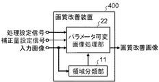
図12は、この発明の実施の形態4の画質改善装置の構成を示す構成図である。
本実施の形態の画質改善装置400は、入力画像に対して処理設定信号と補正量設定信号によって制御される画質改善処理を行い、その結果である画質改善画像を出力する装置であり、領域分類部11とパラメータ可変画像処理部22から構成される。
この装置は適応的な画像処理による画質改善に利用でき、テレビやモニターなどの映像表示装置、デジタルカメラへの搭載、さらには、パーソナルコンピュータ上での画像処理への適用等が考えられる。
FIG. 12 is a block diagram showing the configuration of the image quality improving apparatus according to
The image
This apparatus can be used for image quality improvement by adaptive image processing, and can be applied to video display devices such as televisions and monitors, digital cameras, and image processing on personal computers.
本実施の形態の実施の形態3との相違点は、画像処理部12の代わりにパラメータ可変画像処理部22を置いている点である。パラメータ可変画像処理部22では、処理設定信号と補正量設定信号によって処理内容の切り替えが可能である。画像分類部11の動作については実施の形態3と同様であり、説明を省略する。
The difference of the present embodiment from the third embodiment is that a parameter variable
パラメータ可変画像処理部22は、例えば、図13のような構成である。入力画像と領域分類部11からの出力である分類結果、画像処理内容の切り替えに係る信号である処理設定信号と補正量設定信号を入力、画質改善画像を出力とするもであり、ノイズ低減処理部23、エッジ強調処理部24、及び処理制御部25から成る。また、図において26、30はセレクタ、27、28、29、31、32、33は接続端子を示している。入力画像は、セレクタ26、30の切り替えにより、そのまま通過するか、あるいはノイズ低減処理部23またはエッジ強調処理部24により画像処理が行われ、画質改善画像として出力される。ノイズ低減処理部23とエッジ強調処理部24における補正量は補正量設定信号に応じて変わる。また、セレクタ26、30の切り替えは、分類結果と処理設定信号を基に処理制御部25で生成された制御信号によって制御される。
The parameter variable
ノイズ低減処理部23では入力された画像に対して補正量設定信号に応じた補正量によってノイズ低減処理を行い、その結果を出力する。ノイズ低減処理は、位置(i、j)における入力画像の画素値をI(i、j)、出力画像の画素値をOsmooth2(i、j)、ノイズ低減処理用の補正量設定信号a(0<a<=1)とすると、例えば式(8)のような処理である。
The noise
エッジ強調処理部24では入力された画像に対して補正量設定信号に応じた補正量によってエッジ強調処理を行い、その結果を出力する。エッジ強調処理は、位置(i、j)における入力画像の画素値をI(i、j)、出力画像の画素値をOsharp2(i、j)、エッジ強調処理用の補正量設定信号b(0<b<=1)とすると、例えば式(9)のような処理である。
処理制御部25では、分類結果と処理設定信号を基にセレクタ26、30の切り替えを制御する制御信号を生成する。これにより、入力画像に対してノイズ低減処理とエッジ強調処理のどちらを実行するか、またはいずれの処理も行わずにそのまま通過させるかを制御する。分類結果が平坦部を示す信号であれば、処理制御部25ではセレクタ26を端子28、セレクタ30を端子32に動かすための制御信号を出力し、結果として入力画像にノイズ低減処理が実行される。分類結果が複雑部を示す信号であれば、セレクタ26を端子29に、セレクタ30を端子33に動かすための制御信号を出力し、結果として入力画像にエッジ強調処理が実行される。
The
ただし、処理設定信号によりこれらの処理のオンオフの切り替えが可能である。処理制御部25においてノイズ低減処理が不要であるという処理設定信号を受け取った場合、分類結果が平坦部を示す信号であれば、セレクタ26を端子27、セレクタ30を端子31に動かすための制御信号を出力し、結果として入力画像がそのまま出力される。また、エッジ強調処理が不要であるという処理設定信号を受け取り、かつ、分類結果が複雑部を示す信号であった場合にも同様に、セレクタ26を端子27、セレクタ30を端子31に動かすための制御信号を出力し、結果として入力画像がそのまま出力される。
However, these processes can be switched on and off by a process setting signal. If the
補正量設定信号や処理設定信号は、ユーザにより設定可能である。例えば、テレビの場合にはリモコン等が設定のための入力装置として利用される。また、パソコンでは、キーボードやマウスで入力できる。
また、入力画像の状態を判断して、自動的に設定されるようにしても良い。例えば、テレビで放送を受信する場合、受信波の強度を測定し、受信状態が良好と判断すれば、ノイズ低減処理を不要とするよう処理設定信号を自動設定するようにしても良い。
The correction amount setting signal and the processing setting signal can be set by the user. For example, in the case of a television, a remote controller or the like is used as an input device for setting. On a personal computer, input can be done with a keyboard or mouse.
Alternatively, the state of the input image may be determined and automatically set. For example, when a broadcast is received on a television, the processing setting signal may be automatically set so that noise reduction processing is not necessary if the intensity of the received wave is measured and it is determined that the reception state is good.
本実施の形態によれば、粗い模様部分において処理の切り替えによる不自然な境界の発生を防ぎ、かつ、補正量の変更や処理のオンオフが可能となり、ユーザの好みに応じたより高い画質改善効果が得られる。 According to the present embodiment, it is possible to prevent the occurrence of an unnatural boundary due to switching of processing in a rough pattern portion, and it is possible to change the correction amount and turn on / off the processing, so that a higher image quality improvement effect according to user preferences can get.
実施の形態5.
図14はこの発明の実施の形態5の映像表示装置の構成を示す構成図である。
本実施の形態の映像表示装置500は、入力映像に対して映像のコンテンツ情報や時間情報を基づいてユーザの好みに応じた画質改善処理を行い、その結果を出力映像として表示する装置であり、画質改善装置400、表示部34、コンテンツ情報取得部35、時間情報取得部36、パラメータ記録装置37から構成される。
FIG. 14 is a block diagram showing the configuration of the video display apparatus according to
The
画質改善装置400は、実施の形態4で示したように、映像の各フレームにおいて、画像内の領域を複数の種別に分類し、その分類に応じて処理を切り替えて画質を改善する装置である。画質改善処理の結果は領域の分類のための閾値や画像処理の補正量などのパラメータにより調整可能である。これらの処理パラメータはパラメータ記録装置37に記録されているパラメータを用いる。
As shown in the fourth embodiment, the image
表示部34では、画質改善装置400から出力される画質改善映像を受け取り、出力映像として画面に表示する。
The
コンテンツ情報取得部35では、コンテンツ情報を取得し、その情報を基にパラメータ記録装置37にコンテンツに関する制御信号を送る。コンテンツ情報は、例えばデジタルテレビなどの場合、番組表から取得することができる。
The content
時間情報取得部36では、時間情報を取得し、その情報を基にパラメータ記録装置37に時間に関する制御信号を送る。時間に関する制御信号は、例えば、「朝」、「昼」、「夜」などの時間帯を示す信号である。また、曜日を示す信号でもよい。
The time
パラメータ記録装置37では、コンテンツ別、時間帯別に画質改善のためのパラメータを記録する。ここに記録された処理パラメータは、画質改善装置400において画質を改善する際に参照される。処理パラメータを参照する際にアクセスする位置は、コンテンツ情報取得部35、時間情報取得部36から送られる制御信号により制御され、例えば、コンテンツ情報取得部35から「コンテンツ1」、時間情報所得部36から「夜」へのアクセスを指示する制御信号が送られた場合、38に示す位置に記録された処理パラメータが参照される。また、パラメータ記録装置37はユーザによって処理パラメータが変更された際に、パラメータ設定信号を受け取り、新たな処理パラメータを記録する。処理パラメータの記録位置は、参照時と同様にコンテンツ情報取得部35と時間情報所得部36から送られる制御信号によって制御される。
The
本実施の形態では、画質改善装置400において処理パラメータを自由に設定できるため、ユーザは自分に適した高画質な映像を楽しむことができる。パラメータ記録装置37において、コンテンツの種別ごとに処理パラメータを記録する機能を備えているため、記録された処理パラメータを次回の表示に反映させることで、処理パラメータ調整の手間を省くことが可能である。また、時間帯ごとに処理パラメータを記録する機能を備えているため、1台のテレビを複数のユーザが使う場合にも対応できる。また、あらかじめコンテンツの種別ごとに適当な処理パラメータをパラメータ記録装置37に記録しておくことで、処理パラメータの調整が煩わしいと感じるユーザにも対応できる。
In this embodiment, since the processing parameters can be freely set in the image
本実施の形態によれば、画像内の領域の種別に応じた適切な処理がユーザの好みに応じた処理パラメータによって行われるため高い画質改善効果が得られるとともに、コンテンツの種別や時間帯に応じて処理パラメータを記録することで処理パラメータ調整の手間を軽減しユーザの負担を軽減することができる。 According to the present embodiment, since appropriate processing according to the type of region in the image is performed with processing parameters according to the user's preference, a high image quality improvement effect is obtained, and according to the type of content and time zone By recording the processing parameters, it is possible to reduce the burden of adjusting the processing parameters and reduce the burden on the user.
100、200 領域分類装置
1 領域分割部
2 広さ算出部
3 判定部
4 分類結果生成部
9 相対評価による判定部
300、400 画質改善装置
11 領域分類部
12 画像処理部
13、23 ノイズ低減処理部
14、24 エッジ強調処理部
15、25 処理制御部
22 パラメータ可変画像処理部
500 映像表示装置
34 表示部
35 コンテンツ情報取得部
36 時間情報取得部
37 パラメータ記憶装置
DESCRIPTION OF SYMBOLS 100,200
Claims (12)
前記領域分割部により得られた各領域の広さ情報を取得する広さ算出部と、
前記広さ算出部により得られた広さ情報を基に各領域の種別を判定する判定部と、
前記領域分割部により得られた分割結果と前記判定部により得られた各領域の判定結果に基づき画素ごとの分類結果を生成する分類結果生成部とを備えたことを特徴とする領域分類装置において、
前記広さ算出部は、各領域に属する画素数をその領域の広さ情報とし、
前記判定部は、判定対象である注目領域の広さとその周囲の領域との広さの比較を行い、広さの相対的な評価により各領域を複数の種別に分類することを特徴とする領域分類装置。 A region dividing unit that divides the input image into regions composed of pixels having similar characteristics to each other;
An area calculation unit for acquiring area information of each area obtained by the area dividing unit;
A determination unit that determines the type of each area based on the area information obtained by the area calculation unit;
An area classification apparatus comprising: a classification result generation unit configured to generate a classification result for each pixel based on a division result obtained by the area division unit and a determination result of each area obtained by the determination unit. ,
Before Kihiro calculator is the number of pixels belonging to each area and size information of the region,
The determination unit compares a size of a region of interest as a determination target with a surrounding region, and classifies each region into a plurality of types based on a relative evaluation of the size. Classification device.
前記領域分割ステップにより得られた各領域の広さ情報を取得する広さ算出ステップと、
前記広さ算出ステップにより得られた広さ情報を基に各領域の種別を判定する判定ステップと、
前記領域分割ステップにより得られた分割結果と前記判定ステップにより得られた各領域の判定結果に基づき画素ごとの分類結果を生成する分類結果生成ステップとを備えた領域分類方法において、
前記広さ算出ステップは、各領域に属する画素数をその領域の広さ情報とし、
前記判定ステップは、判定対象である注目領域の広さとその周囲の領域との広さの比較を行い、広さの相対的な評価により各領域を複数の種別に分類することを特徴とする領域分類方法。 A region dividing step for dividing the input image into regions composed of pixels having similar characteristics to each other;
An area calculating step for acquiring area information of each area obtained by the area dividing step;
A determination step of determining the type of each region based on the width information obtained by the width calculation step;
In an area classification method comprising: a classification result generation step for generating a classification result for each pixel based on a division result obtained by the area division step and a determination result of each area obtained by the determination step;
Before Kihiro calculation step is the number of pixels belonging to each area and size information of the region,
The determination step includes comparing a width of a region of interest as a determination target with a surrounding region, and classifying each region into a plurality of types based on a relative evaluation of the width. Classification method.
Priority Applications (1)
| Application Number | Priority Date | Filing Date | Title |
|---|---|---|---|
| JP2009124052A JP5434265B2 (en) | 2009-05-22 | 2009-05-22 | Region classification device, image quality improvement device, video display device, and methods thereof |
Applications Claiming Priority (1)
| Application Number | Priority Date | Filing Date | Title |
|---|---|---|---|
| JP2009124052A JP5434265B2 (en) | 2009-05-22 | 2009-05-22 | Region classification device, image quality improvement device, video display device, and methods thereof |
Publications (3)
| Publication Number | Publication Date |
|---|---|
| JP2010271987A JP2010271987A (en) | 2010-12-02 |
| JP2010271987A5 JP2010271987A5 (en) | 2012-06-28 |
| JP5434265B2 true JP5434265B2 (en) | 2014-03-05 |
Family
ID=43419949
Family Applications (1)
| Application Number | Title | Priority Date | Filing Date |
|---|---|---|---|
| JP2009124052A Expired - Fee Related JP5434265B2 (en) | 2009-05-22 | 2009-05-22 | Region classification device, image quality improvement device, video display device, and methods thereof |
Country Status (1)
| Country | Link |
|---|---|
| JP (1) | JP5434265B2 (en) |
Families Citing this family (12)
| Publication number | Priority date | Publication date | Assignee | Title |
|---|---|---|---|---|
| US9955103B2 (en) | 2013-07-26 | 2018-04-24 | Panasonic Intellectual Property Management Co., Ltd. | Video receiving device, appended information display method, and appended information display system |
| WO2015015712A1 (en) | 2013-07-30 | 2015-02-05 | パナソニックIpマネジメント株式会社 | Video reception device, added-information display method, and added-information display system |
| WO2015033501A1 (en) | 2013-09-04 | 2015-03-12 | パナソニックIpマネジメント株式会社 | Video reception device, video recognition method, and additional information display system |
| JP6281125B2 (en) | 2013-09-04 | 2018-02-21 | パナソニックIpマネジメント株式会社 | Video receiving apparatus, video recognition method, and additional information display system |
| JP6194483B2 (en) | 2014-03-26 | 2017-09-13 | パナソニックIpマネジメント株式会社 | Video receiving apparatus, video recognition method, and additional information display system |
| WO2015145493A1 (en) | 2014-03-26 | 2015-10-01 | パナソニックIpマネジメント株式会社 | Video receiving device, video recognition method, and supplementary information display system |
| EP3171609B1 (en) | 2014-07-17 | 2021-09-01 | Panasonic Intellectual Property Management Co., Ltd. | Recognition data generation device, image recognition device, and recognition data generation method |
| EP3185577B1 (en) | 2014-08-21 | 2018-10-24 | Panasonic Intellectual Property Management Co., Ltd. | Content identification apparatus and content identification method |
| CN106233742B (en) | 2014-08-26 | 2019-07-09 | 松下知识产权经营株式会社 | Display control unit, display control method and recording medium |
| US10620826B2 (en) | 2014-08-28 | 2020-04-14 | Qualcomm Incorporated | Object selection based on region of interest fusion |
| US9542751B2 (en) * | 2015-05-08 | 2017-01-10 | Qualcomm Incorporated | Systems and methods for reducing a plurality of bounding regions |
| CN115661667B (en) * | 2022-12-13 | 2023-04-07 | 济宁市土哥农业服务有限公司 | Method for identifying impurities in descurainia sophia seeds based on computer vision |
Family Cites Families (6)
| Publication number | Priority date | Publication date | Assignee | Title |
|---|---|---|---|---|
| JPH0666884B2 (en) * | 1985-02-23 | 1994-08-24 | 日本電信電話株式会社 | Halftone photo area identification method |
| JPH07220091A (en) * | 1994-02-04 | 1995-08-18 | Canon Inc | Device and method for image processing |
| JP2812232B2 (en) * | 1995-01-27 | 1998-10-22 | 日本電気株式会社 | Halftone image data compression method |
| JP3644716B2 (en) * | 1995-02-23 | 2005-05-11 | 三菱電機株式会社 | Image region separation method and image region separation device, and image processing method and image processing device |
| JPH1175063A (en) * | 1997-08-28 | 1999-03-16 | Canon Inc | Picture processing device and method therefor |
| JP3629959B2 (en) * | 1998-07-06 | 2005-03-16 | ミノルタ株式会社 | Image recognition device |
-
2009
- 2009-05-22 JP JP2009124052A patent/JP5434265B2/en not_active Expired - Fee Related
Also Published As
| Publication number | Publication date |
|---|---|
| JP2010271987A (en) | 2010-12-02 |
Similar Documents
| Publication | Publication Date | Title |
|---|---|---|
| JP5434265B2 (en) | Region classification device, image quality improvement device, video display device, and methods thereof | |
| JP4558806B2 (en) | Visual processing device, visual processing method, program, display device, and integrated circuit | |
| US9218653B2 (en) | Method and apparatus for dynamic range enhancement of an image | |
| US7869649B2 (en) | Image processing device, image processing method, program, storage medium and integrated circuit | |
| JP5121294B2 (en) | Image processing method, image processing apparatus, program, recording medium, and integrated circuit | |
| US20090022396A1 (en) | Image processing device, image processing method, image processing system, program, storage medium, and integrated circuit | |
| JP4778859B2 (en) | Image processing apparatus, image processing method, and image processing program | |
| JP4118688B2 (en) | System and method for enhancement based on segmentation of video images | |
| JP6287337B2 (en) | Image processing apparatus, image processing method, image processing system, and program | |
| CN108090887B (en) | Video image processing method and device | |
| JP4758999B2 (en) | Image processing program, image processing method, and image processing apparatus | |
| US20150248221A1 (en) | Image processing device, image processing method, image processing system, and non-transitory computer readable medium | |
| JP2009038794A (en) | Image processor, image processing method, image processing system, program, recording medium, and integrated circuit | |
| JP2013041565A (en) | Image processor, image display device, image processing method, computer program, and recording medium | |
| JP5781370B2 (en) | Image processing apparatus, image processing method, image display apparatus including image processing apparatus, program, and recording medium | |
| US20100272372A1 (en) | Image Processing Apparatus and Image Processing Method | |
| JP4467416B2 (en) | Tone correction device | |
| US20170046817A1 (en) | Image processing apparatus, image processing method and computer readable medium | |
| US9600858B1 (en) | Visually comfortable content-adaptive dithering for super-resolution | |
| JP5966603B2 (en) | Image processing apparatus, image processing method, image processing program, and recording medium | |
| KR101634652B1 (en) | Method and apparatus for intensificating contrast in image | |
| JP2005285071A (en) | Image processor | |
| JP6701687B2 (en) | Image processing apparatus, image processing method, and image processing program | |
| JP2011022779A (en) | Image correction apparatus, image correction method and program | |
| JP2010288040A (en) | Method and device for correcting contour |
Legal Events
| Date | Code | Title | Description |
|---|---|---|---|
| A521 | Request for written amendment filed |
Free format text: JAPANESE INTERMEDIATE CODE: A523 Effective date: 20120515 |
|
| A621 | Written request for application examination |
Free format text: JAPANESE INTERMEDIATE CODE: A621 Effective date: 20120515 |
|
| A977 | Report on retrieval |
Free format text: JAPANESE INTERMEDIATE CODE: A971007 Effective date: 20130225 |
|
| A131 | Notification of reasons for refusal |
Free format text: JAPANESE INTERMEDIATE CODE: A131 Effective date: 20130305 |
|
| A521 | Request for written amendment filed |
Free format text: JAPANESE INTERMEDIATE CODE: A523 Effective date: 20130415 |
|
| TRDD | Decision of grant or rejection written | ||
| A01 | Written decision to grant a patent or to grant a registration (utility model) |
Free format text: JAPANESE INTERMEDIATE CODE: A01 Effective date: 20131112 |
|
| A61 | First payment of annual fees (during grant procedure) |
Free format text: JAPANESE INTERMEDIATE CODE: A61 Effective date: 20131125 |
|
| R151 | Written notification of patent or utility model registration |
Ref document number: 5434265 Country of ref document: JP Free format text: JAPANESE INTERMEDIATE CODE: R151 |
|
| R250 | Receipt of annual fees |
Free format text: JAPANESE INTERMEDIATE CODE: R250 |
|
| R250 | Receipt of annual fees |
Free format text: JAPANESE INTERMEDIATE CODE: R250 |
|
| R250 | Receipt of annual fees |
Free format text: JAPANESE INTERMEDIATE CODE: R250 |
|
| R250 | Receipt of annual fees |
Free format text: JAPANESE INTERMEDIATE CODE: R250 |
|
| R250 | Receipt of annual fees |
Free format text: JAPANESE INTERMEDIATE CODE: R250 |
|
| LAPS | Cancellation because of no payment of annual fees |