JP5433420B2 - Collective lead for spinal cord stimulation - Google Patents
Collective lead for spinal cord stimulation Download PDFInfo
- Publication number
- JP5433420B2 JP5433420B2 JP2009540485A JP2009540485A JP5433420B2 JP 5433420 B2 JP5433420 B2 JP 5433420B2 JP 2009540485 A JP2009540485 A JP 2009540485A JP 2009540485 A JP2009540485 A JP 2009540485A JP 5433420 B2 JP5433420 B2 JP 5433420B2
- Authority
- JP
- Japan
- Prior art keywords
- electrodes
- electrode
- dorsal root
- lead
- tubular body
- Prior art date
- Legal status (The legal status is an assumption and is not a legal conclusion. Google has not performed a legal analysis and makes no representation as to the accuracy of the status listed.)
- Expired - Fee Related
Links
- 230000000638 stimulation Effects 0.000 title claims description 48
- 210000000278 spinal cord Anatomy 0.000 title description 36
- 210000003594 spinal ganglia Anatomy 0.000 claims description 62
- 230000004936 stimulating effect Effects 0.000 claims description 9
- 230000000694 effects Effects 0.000 claims description 7
- 210000001519 tissue Anatomy 0.000 description 18
- 238000000034 method Methods 0.000 description 12
- 208000002193 Pain Diseases 0.000 description 10
- 230000036407 pain Effects 0.000 description 10
- 210000000273 spinal nerve root Anatomy 0.000 description 10
- 210000000944 nerve tissue Anatomy 0.000 description 7
- 210000004126 nerve fiber Anatomy 0.000 description 5
- 230000001537 neural effect Effects 0.000 description 5
- 210000001175 cerebrospinal fluid Anatomy 0.000 description 4
- 101150083710 DRG3 gene Proteins 0.000 description 3
- 102100028945 Developmentally-regulated GTP-binding protein 1 Human genes 0.000 description 3
- 102100037711 Developmentally-regulated GTP-binding protein 2 Human genes 0.000 description 3
- 208000003098 Ganglion Cysts Diseases 0.000 description 3
- 101000838507 Homo sapiens Developmentally-regulated GTP-binding protein 1 Proteins 0.000 description 3
- 101000880940 Homo sapiens Developmentally-regulated GTP-binding protein 2 Proteins 0.000 description 3
- 101000979748 Homo sapiens Protein NDRG1 Proteins 0.000 description 3
- 208000005400 Synovial Cyst Diseases 0.000 description 3
- 210000001951 dura mater Anatomy 0.000 description 3
- 230000002349 favourable effect Effects 0.000 description 3
- 238000007726 management method Methods 0.000 description 3
- 210000005036 nerve Anatomy 0.000 description 3
- 230000001174 ascending effect Effects 0.000 description 2
- 210000000988 bone and bone Anatomy 0.000 description 2
- 238000013461 design Methods 0.000 description 2
- 238000002684 laminectomy Methods 0.000 description 2
- 210000000653 nervous system Anatomy 0.000 description 2
- 210000000578 peripheral nerve Anatomy 0.000 description 2
- 230000003014 reinforcing effect Effects 0.000 description 2
- 230000001953 sensory effect Effects 0.000 description 2
- 210000001032 spinal nerve Anatomy 0.000 description 2
- 238000002054 transplantation Methods 0.000 description 2
- 206010001497 Agitation Diseases 0.000 description 1
- 208000008035 Back Pain Diseases 0.000 description 1
- 240000006829 Ficus sundaica Species 0.000 description 1
- 206010033425 Pain in extremity Diseases 0.000 description 1
- 206010033799 Paralysis Diseases 0.000 description 1
- 210000003484 anatomy Anatomy 0.000 description 1
- 210000001217 buttock Anatomy 0.000 description 1
- 238000004590 computer program Methods 0.000 description 1
- 230000005684 electric field Effects 0.000 description 1
- 229920005570 flexible polymer Polymers 0.000 description 1
- 238000002594 fluoroscopy Methods 0.000 description 1
- 238000002513 implantation Methods 0.000 description 1
- 230000001788 irregular Effects 0.000 description 1
- 230000007794 irritation Effects 0.000 description 1
- 238000002690 local anesthesia Methods 0.000 description 1
- 210000004705 lumbosacral region Anatomy 0.000 description 1
- 239000000463 material Substances 0.000 description 1
- 238000012986 modification Methods 0.000 description 1
- 230000004048 modification Effects 0.000 description 1
- 210000003205 muscle Anatomy 0.000 description 1
- 230000007433 nerve pathway Effects 0.000 description 1
- 230000007935 neutral effect Effects 0.000 description 1
- 231100000862 numbness Toxicity 0.000 description 1
- 238000011084 recovery Methods 0.000 description 1
- 230000009467 reduction Effects 0.000 description 1
- 238000012827 research and development Methods 0.000 description 1
- 230000035807 sensation Effects 0.000 description 1
- 229920002379 silicone rubber Polymers 0.000 description 1
- 239000004945 silicone rubber Substances 0.000 description 1
- 238000001356 surgical procedure Methods 0.000 description 1
- 208000024891 symptom Diseases 0.000 description 1
- 230000001225 therapeutic effect Effects 0.000 description 1
Images


Classifications
-
- A—HUMAN NECESSITIES
- A61—MEDICAL OR VETERINARY SCIENCE; HYGIENE
- A61N—ELECTROTHERAPY; MAGNETOTHERAPY; RADIATION THERAPY; ULTRASOUND THERAPY
- A61N1/00—Electrotherapy; Circuits therefor
- A61N1/02—Details
- A61N1/04—Electrodes
- A61N1/05—Electrodes for implantation or insertion into the body, e.g. heart electrode
- A61N1/0551—Spinal or peripheral nerve electrodes
- A61N1/0553—Paddle shaped electrodes, e.g. for laminotomy
Description
(関連出願の相互参照)
本願は、2006年12月6日付けで出願された米国仮特許出願第60/873,464号(弁護士整理番号No.10088-706.101)を基礎とする優先権を主張するものであり、すべての目的において参考にここに一体に統合される。
(Cross-reference of related applications)
This application claims priority based on US Provisional Patent Application No. 60 / 873,464 filed December 6, 2006 (Attorney Docket No. 10088-706.101) for all purposes. It is integrated here as a reference.
(連邦政府支援の研究開発でなされた発明に対する権利に関する陳述)
適用なし。
(Statement regarding rights to inventions made in federal-supported research and development)
Not applicable.
(コンパクトディスクで提出する「配列表」、表、またはコンピュータプログラムリストの付録)
適用なし。
(Appendix of “Sequence List”, table or computer program list to be submitted on compact disc)
Not applicable.
1960年代から、疼痛管理(軽減)を目的として脊髄に特定の電気エネルギを加えることが積極的に行われてきた。脊髄神経組織に電場をかけると、刺激された神経組織に関連する体の領域から伝達されるある種の疼痛を効率的に麻痺させる(マスクされる)ことが知られている。こうした麻痺は、痛みを感じる体の領域における無感覚または疼き、錯感覚として知られている。電気エネルギの付加はゲートコントロール理論に基づいている。メルザックおよびウォールにより発表されたこの理論によれば、触覚、冷覚、振動覚などの太い神経線維の情報(興奮)を受けると、痛みを与える細い神経線維の情報(興奮)を遮断または閉じることが提唱されている。したがって、その結果として痛みが緩和されることが期待される。ゲートコントロール理論に基づいて脊髄の太い神経線維に電気刺激を与えると、その脊髄部分における細い神経線維の情報が抑制または排除され、その脊髄部分より下方の他のすべての情報が同様に抑制または排除される。こうした脊髄部分への電気刺激は、脊髄後索刺激として知られているが、本願においては脊髄電気刺激法(SCS:Spinal Cord Stimulation)またはSCSという。 Since the 1960s, specific electrical energy has been actively applied to the spinal cord for the purpose of pain management (reduction). It is known that applying an electric field to spinal nerve tissue effectively paralyzes (masks) certain types of pain transmitted from areas of the body associated with the stimulated nerve tissue. Such paralysis is known as numbness or soreness or illusion in areas of the body that feel pain. The addition of electrical energy is based on gate control theory. According to this theory published by Melzac and Wall, when information (excitement) of thick nerve fibers such as touch, cold, and vibration is received, information (excitement) of fine nerve fibers that cause pain is blocked or closed. Has been proposed. Therefore, it is expected that pain will be relieved as a result. When electrical stimulation is applied to a thick nerve fiber in the spinal cord based on gate control theory, information on the thin nerve fiber in the spinal cord part is suppressed or eliminated, and all other information below the spinal cord part is similarly suppressed or eliminated. Is done. Such electrical stimulation to the spinal cord portion is known as spinal cord retrostimulus stimulation, but in this application is referred to as spinal cord stimulation (SCS) or SCS.
図1Aおよび図1Bは、従来式のSCSシステム10の構成を示すものである。従来式のSCSシステムは、移植可能な電源または移植可能なパルス発生器(IPG:Implantable Pulse Generator)12と、移植可能なリード14とを有する。こうしたIPG12は、ペースメーカと同様の大きさと重量を有し、通常、患者Pの臀部に移植される。蛍光透視法を用いて、図1Bに示すように、脊柱の硬膜上腔Eにリード14を移植して、硬膜硬膜Sに対向するように配置する。リード14は、硬膜外ニードル(たとえば経皮リード)を用いて皮膚を通して移植されるか、(パドルリードについて)微小椎弓切除術による直接的かつ外科手術的に移植される。 1A and 1B show a configuration of a conventional SCS system 10. A conventional SCS system has an implantable power supply or implantable pulse generator (IPG) 12 and an implantable lead 14. Such an IPG 12 has the same size and weight as a pacemaker and is usually implanted in the buttocks of a patient P. As shown in FIG. 1B, the lead 14 is transplanted into the epidural space E of the spinal column and placed so as to face the dura mater S using fluoroscopy. The lead 14 is implanted through the skin using an epidural needle (eg, a percutaneous lead) or directly and surgically via a micro laminectomy (for paddle leads).
図2は、従来式のパドルリード16および経皮リード18の具体例を示す。パドルリード16は、通常、表面上に1つまたはそれ以上に電極20を有する平板状のシリコーンゴムの形態を有する。パドルリード16の具体的な寸法を図3に示す。一方、経皮リード18は、その周囲に延びる1つまたはそれ以上に電極20を有するチューブまたはロッド状の形態を有する。経皮リード18の具体的な寸法を図4に示す。
FIG. 2 shows a specific example of a
経皮リード18の移植手術は、通常、(背および足の疼痛管理に対して)腰部領域を切開すること、または(腕の疼痛管理に対して)上背部および頸部を切開することを含む。経皮ニードルを切開口から硬膜上腔内に配置し、電気刺激を与えたときに、患者の痛みを感じる領域に心地よい疼き(錯感覚)が生じる脊髄領域に達するまで脊髄の上方に沿って挿入する。この領域に配置するために、患者が刺激範囲に対してフィードバックする際に、リードを移動させつつ、オンオフを繰り返す。患者がこの操作に関与して、脊髄に対する適正な位置をオペレータに指示するため、局所麻酔を用いてこの移植手術を行う。
Transplantation of the
パドルリード16の移植手術は、通常、リードを移植するための微小椎弓切除術により行われる。切開口は、刺激すべき脊髄領域の少し下方または少し上方に形成される。硬膜上腔は椎孔を介して直接的に挿入され、パドルリード16は脊髄を刺激するためにその領域の上方に配置される。刺激のための標的領域は、経皮リード18による脊柱刺激の試行錯誤の際に、この手術の前に特定される。
Transplantation of the
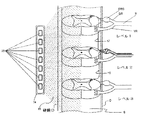
こうしたSCSシステムは、いくらかの患者に対して効果的に疼痛を緩和するが、数多くの問題点を有する。最初に、図5に示すように、リード14は、電極20が脊柱の広範部位および関連する脊髄神経組織を刺激するように、脊柱硬膜D上に配置される。脊髄は連続体であり、脊髄の3つの脊髄レベルを示す。図示のため、脊髄レベルは、後根DRと前根VRとが脊髄Sに結合する部分を示す脊髄の複数の部分領域である。末梢神経Nは、後根DRおよび後根神経節DRGと、前根VRとに分かれ、これらは脊髄Sに延びている。上行経路17がレベル2とレベル1の間に図示され、下行経路19がレベル2とレベル3の間に図示されている。脊髄レベルは、脊髄の複数の脊柱本体部を記述する足に通常用いられる脊柱レベルに対応する。簡略化のため、各脊髄レベルは、一方側のみの神経系を示すが、正常な解剖学的構成は、リードに直接的に隣接する脊髄の側で図示されたものと同様の神経系を有する。
While these SCS systems effectively relieve pain for some patients, they have a number of problems. Initially, as shown in FIG. 5, lead 14 is placed on spinal dura mater D such that
脊髄運動神経組織、すなわち神経前根からの神経組織は、筋肉/運動制御信号を伝達する。脊髄感覚神経組織、すなわち神経後根からの神経組織は、疼痛信号を伝達する。対応する神経前根および神経後根は「個別に」脊髄から延びるが、神経前根および神経後根の神経組織はその直後に合体またはより合わさるものである。したがって、リード14により電気刺激を行うと、脊髄感覚神経組織に加えて脊髄運動神経組織に不要な刺激を与える場合がしばしばある。 Spinal motor nerve tissue, that is, nerve tissue from the anterior root of the nerve, transmits muscle / motor control signals. Spinal sensory nerve tissue, that is, nerve tissue from the nerve dorsal root, transmits pain signals. The corresponding anterior and dorsal roots extend “individually” from the spinal cord, but the neural tissue of the anterior and dorsal roots coalesces or merges immediately thereafter. Therefore, when electrical stimulation is performed by the lead 14, unnecessary stimulation is often given to the spinal motor nerve tissue in addition to the spinal cord sensory nerve tissue.
これらの電極は複数のレベルに拡がるので、形成された刺激エネルギ15は、2以上のレベルの神経組織に与えられ、これらを刺激する。さらに、これら、または他の従来式の非限定的刺激システムは、脊髄や意図した刺激標的以外の他の中立的な組織にも刺激エネルギを与える。本願明細書でいう「非限定的刺激」とは、刺激エネルギが広く差別することなく、神経および脊髄を含むすべての脊髄レベルに与えられることを意味するものである。ただ1つのレベルを刺激するように硬膜外電極の大きさを小さくしても、与えられたエネルギの範囲内にあるすべてのもの(すべての神経線維および他の組織)に無差別に刺激エネルギを与える。さらに硬膜外電極は、より大きいとき、脳脊髄液(Cerebral Spinal Fluid:CSF)の流れを変え、その結果として、局所的な神経興奮状態を変える場合がある。 Since these electrodes extend to multiple levels, the formed stimulation energy 15 is applied to and stimulates two or more levels of neural tissue. In addition, these or other conventional non-limiting stimulation systems also provide stimulation energy to the spinal cord and other neutral tissues other than the intended stimulation target. As used herein, “non-limiting stimulation” means that stimulation energy is applied to all spinal levels including nerves and spinal cord without wide discrimination. Even if the epidural electrode size is reduced to stimulate only one level, all energy (all nerve fibers and other tissues) within the given energy range are indiscriminately stimulated energy give. In addition, epidural electrodes, when larger, can alter the flow of Cerebral Spinal Fluid (CSF) and, as a result, the local neural excitability.
従来式の神経刺激システムが直面する別の課題は、硬膜外電極は、さまざまな組織および脳脊髄液に対して電気エネルギを与える必要がある(すなわちCSF量が脊髄に沿って脊髄軟膜の厚みが変化するときに同様に変化する)ので、所望される神経刺激を得るために必要な刺激エネルギ量を正確に制御することが困難である。したがって、十分な刺激エネルギが所望する刺激領域に到達するように、エネルギ量を増大させることができるものの、刺激エネルギが増大するほど、周辺の組織、構造体または神経経路に対して有害なダメージまたは刺激を与えるおそれが高くなる。 Another challenge facing conventional neurostimulation systems is that epidural electrodes need to provide electrical energy to various tissues and cerebrospinal fluid (ie, the amount of CSF along the spinal cord is the thickness of the spinal puffy coat) So that it is difficult to accurately control the amount of stimulation energy required to obtain the desired neural stimulation. Thus, although the amount of energy can be increased so that sufficient stimulation energy reaches the desired stimulation area, the more stimulation energy, the more harmful damage or damage to surrounding tissues, structures or nerve pathways. The risk of irritation increases.
そこで、刺激エネルギをより正確に、かつ有効に付加することができる改善された刺激システムまたは刺激方法が必要とされている。 Thus, there is a need for an improved stimulation system or method that can add stimulation energy more accurately and effectively.
本発明は、脊柱に沿った脊髄レベルなどのさまざまな標的位置にある脊髄組織を同時に刺激するための装置、システムおよび方法を提供する。上述のように、脊髄は連続体であり、数多くの脊髄レベルを有するものと考えられる。脊髄レベルは、たとえば後根と前根とが脊髄に結合する脊髄の複数の部分領域と考えられる。脊髄レベルは、脊椎の脊椎部分に対応するものであり、脊椎の脊椎本体を記述するために広く用いられる。 The present invention provides an apparatus, system and method for simultaneously stimulating spinal cord tissue at various target locations, such as spinal level along the spinal column. As mentioned above, the spinal cord is a continuum and is thought to have numerous spinal levels. The spinal level is considered to be a plurality of partial areas of the spinal cord where the dorsal and anterior roots join the spinal cord, for example. The spinal level corresponds to the spinal portion of the spine and is widely used to describe the spinal body of the spine.
広範な領域を包括的に刺激する従来式のSCSとは対照的に、標的部位は個別に刺激される。これは、疼痛症状に対するより有効な治療を提供し、副作用を低減する。本発明は、さまざまな脊髄レベルにある標的を絞って刺激するための装置、システムおよび方法を提供する。さらに、いくつかの実施形態は、各標的レベル内でのさらなる選択性を提供する。 In contrast to conventional SCS, which comprehensively stimulates a wide area, the target sites are stimulated individually. This provides a more effective treatment for pain symptoms and reduces side effects. The present invention provides devices, systems and methods for squeezing and stimulating targets at various spinal levels. Furthermore, some embodiments provide additional selectivity within each target level.
好適な実施形態に係る装置、システムおよび方法は、後根DR、とりわけ後根神経節DRGなどの特定の神経組織におけるさまざまな脊髄レベルを刺激するものである。ここで開示する具体例は、さまざまな脊髄レベルにある後根神経節に対する特定の刺激を図示するが、実施形態が限定されるものではない。 The devices, systems and methods according to preferred embodiments stimulate various spinal levels in specific neural tissues such as the dorsal root DR, especially the dorsal root ganglion DRG. While the specific examples disclosed herein illustrate specific stimuli for dorsal root ganglia at various spinal levels, embodiments are not limited.
本発明の第1の態様によれば、複数の後根神経節を刺激する方法が提供される。いくつかの実施形態では、この方法は、長手方向軸を有し、これに沿って配置された少なくとも2つの電極を含むリードを硬膜上腔内に配置するステップと、選択的に刺激を与えることができるように、少なくとも2つの電極のそれぞれが複数の後根神経節のうちの1つの距離の範囲内に配置されるようにリードを位置合わせするステップと、複数の後根神経節のうちの少なくとも1つを選択的に刺激するようにリードに電気的なエネルギを供給するステップとを有する。いくつかの事例において、電気的なエネルギを供給するステップは、互いに隣接しない少なくとも2つの後根神経節に選択的に刺激を与えるようにリードに電気的なエネルギを供給するステップを含む。他の事例では、リードは、互いに隣接する少なくとも2つの後根神経節に選択的に刺激を与える。さまざまな組み合わせの後根神経節を同時に、または任意のパターンで刺激してもよい。 According to a first aspect of the invention, a method for stimulating a plurality of dorsal root ganglia is provided. In some embodiments, the method includes selectively placing a lead in the epidural space having a longitudinal axis and including a lead including at least two electrodes disposed along the longitudinal axis. Aligning the leads such that each of the at least two electrodes is positioned within a distance of one of the plurality of dorsal root ganglia; and Supplying electrical energy to the leads to selectively stimulate at least one of In some instances, supplying electrical energy includes supplying electrical energy to the lead to selectively stimulate at least two dorsal root ganglia that are not adjacent to each other. In other cases, the lead selectively stimulates at least two dorsal root ganglia adjacent to each other. Various combinations of dorsal root ganglia may be stimulated simultaneously or in any pattern.
いくつかの実施形態では、少なくとも2つの電極は、長手方向軸に沿って配置された一連の電極を含む。こうした実施形態では、リードに電気的なエネルギを供給するステップは、一連の電極のうちの個別の電極であって、上記距離の範囲内に配置され、関連する後根神経節を選択的に刺激することができる個別の電極を選択的に電気的なエネルギを供給するステップを含む。個別の電極間の距離のいくつかが不規則であることが理解される。 In some embodiments, the at least two electrodes include a series of electrodes disposed along the longitudinal axis. In such embodiments, the step of supplying electrical energy to the lead is an individual electrode of the series of electrodes that is positioned within the distance and selectively stimulates the associated dorsal root ganglion. Selectively supplying electrical energy to individual electrodes that can be included. It will be appreciated that some of the distances between the individual electrodes are irregular.
本発明の別の態様によれば、体の組織内の神経を刺激するための伸縮自在のリードが提供される。いくつかの実施形態では、伸縮自在のリードは、近位端、遠位端、およびこれらの間のルーメンを有し、表面上に少なくとも1つの電極を有する長い管状本体部を有する。またリードは、近位端、遠位端、および表面上に配置された少なくとも1つの電極を有する内側構造体を有し、内側構造体は、その遠位端が長い管状本体部の遠位端を越えて延びるようにルーメン内を移動することができ、内側構造体は、リードが組織内を押し進められるよう十分な強度を有するように、近位端および遠位端の間に延びる強化部材を有する。 In accordance with another aspect of the present invention, a retractable lead for stimulating nerves in body tissue is provided. In some embodiments, the retractable lead has a long tubular body having a proximal end, a distal end, and a lumen therebetween, with at least one electrode on the surface. The lead also has an inner structure having a proximal end, a distal end, and at least one electrode disposed on the surface, the inner structure being a distal end of a tubular body having a long distal end. And the inner structure includes a reinforcing member extending between the proximal and distal ends so that the lead is strong enough to be advanced through the tissue. Have.
管状本体部および内側構造体はさまざまな断面形状を有していてもよい。いくつかの実施形態では、内側構造体は、ルーメン内での回転を防止するような形状を有していてもよい。さもなければ、管状本体部は、内側構造体の周りで回転することを防止するような形状を有していてもよい。いくつかの実施形態では、管状本体部は、楕円形または長方形のルーメンを有する The tubular body and inner structure may have various cross-sectional shapes. In some embodiments, the inner structure may have a shape that prevents rotation within the lumen. Otherwise, the tubular body may have a shape that prevents rotation around the inner structure. In some embodiments, the tubular body has an oval or rectangular lumen.
通常、少なくとも1つの電極は、実質的に長手方向に位置合わせされている。しかし、いくつかの電極は、互いに隣接するか、または互いに対して長手方向にずれていてもよい。任意であるが、複数の電極は独立してエネルギ供給することが可能であってもよい。 Typically, at least one electrode is substantially longitudinally aligned. However, some electrodes may be adjacent to each other or may be longitudinally offset relative to each other. Optionally, the plurality of electrodes may be capable of independently supplying energy.
いくつかの実施形態では、内側構造体は、孔を貫通するような寸法を有する。通常、管状本体部は、同様に、こうした移動に適した寸法を有する。 In some embodiments, the inner structure is dimensioned to penetrate the hole. Typically, the tubular body has dimensions suitable for such movement as well.
いくつかの実施形態では、伸縮自在のリードは、近位端、遠位端、およびこれらの間のルーメンを有し、表面上に少なくとも1つの電極を有する追加的な長い管状本体部をさらに備える。この追加的な長い管状本体部は、前記長い管状本体部のルーメン内を移動できるように構成され、内側構造体は、追加的な長い管状本体部のルーメン内を移動することができる。通常、少なくとも1つの電極は、実質的に長手方向に位置合わせされている。 In some embodiments, the retractable lead further comprises an additional long tubular body having a proximal end, a distal end, and a lumen therebetween, and having at least one electrode on the surface. . The additional long tubular body is configured to be movable within the lumen of the long tubular body, and the inner structure can be moved within the lumen of the additional long tubular body. Typically, at least one electrode is substantially longitudinally aligned.
長い管状本体部および内側構造体は、長い管状本体部上の少なくとも1つの電極が第1の後根神経節に位置合わせされる一方、内側構造体上の少なくとも1つの電極が第2の後根神経節に位置合わせされるように移動可能であってもよい。あるいは、長い管状本体部および内側構造体は、長い管状本体部上の少なくとも1つの電極が後根神経節の第1部分に位置合わせされる一方、内側構造体上の少なくとも1つの電極が後根神経節の第2部分に位置合わせされるように移動可能であってもよい。 The long tubular body and the inner structure have at least one electrode on the long tubular body aligned with the first dorsal root ganglion, while at least one electrode on the inner structure has a second dorsal root. It may be movable to align with the ganglion. Alternatively, the long tubular body and the inner structure are such that at least one electrode on the long tubular body is aligned with the first portion of the dorsal root ganglion while at least one electrode on the inner structure is on the dorsal root. It may be movable to align with the second part of the ganglion.
本発明に係る別の態様によれば、少なくとも1つの後根神経節を刺激する方法が提供される。いくつかの実施形態によれば、この方法は、伸縮自在のリードを後根神経節に向かって移動させるステップを有し、前記リードは、近位端、遠位端、およびこれらの間のルーメンを有し、表面上に少なくとも1つの電極を有する長い管状本体部と、表面上に少なくとも1つの電極を有する内側構造体であって、その遠位端が長い管状本体部の遠位端を越えて延びるようにルーメン内を移動することができる内側構造体とを有する。この方法は、後根神経節に刺激を与えるために、少なくとも1つの電極を後根神経節の付近に配置するステップをさらに有する。 According to another aspect of the present invention, a method for stimulating at least one dorsal root ganglion is provided. According to some embodiments, the method includes moving a retractable lead toward the dorsal root ganglion, the lead including a proximal end, a distal end, and a lumen therebetween. A long tubular body having at least one electrode on the surface and an inner structure having at least one electrode on the surface, the distal end of which extends beyond the distal end of the long tubular body And an inner structure that is movable within the lumen to extend. The method further comprises placing at least one electrode in the vicinity of the dorsal root ganglion to provide stimulation to the dorsal root ganglion.
いくつかの実施形態によれば、伸縮自在のリードを移動させるステップは、少なくとも部分的に孔を貫通するようにリードを移動させるステップを含む。また伸縮自在のリードを移動させるステップは、脊柱の外部から水平方向に後根神経節に接近させるステップを含むものであってもよい。あるいは、伸縮自在のリードを移動させるステップは、伸縮自在のリードが硬膜上腔を貫通するように移動させるステップを含むものであってもよい。 According to some embodiments, moving the retractable lead includes moving the lead to at least partially penetrate the hole. The step of moving the telescopic lead may include the step of approaching the dorsal root ganglion in the horizontal direction from the outside of the spinal column. Alternatively, the step of moving the telescopic lead may include the step of moving the telescopic lead so as to penetrate the epidural space.
通常、電極を配置するステップは、後根神経節に隣接する内側構造体上の少なくとも1つの電極を後根神経節の付近に配置するために、内側構造体を伸張または収縮させるステップを含む。 Typically, placing the electrodes includes stretching or contracting the inner structure to place at least one electrode on the inner structure adjacent to the dorsal root ganglion in the vicinity of the dorsal root ganglion.
いくつかの実施形態によれば、電極を配置するステップは、内側構造体上に配置された少なくとも1つの電極を後根神経節に隣接して配置させ、管状本体部上に配置された少なくとも1つの電極を別の後根神経節に隣接して配置させるように、内側構造体を移動させるステップを含む。後根神経節および別の後根神経節は隣接する脊髄レベル上にあってもよい。しかし、後根神経節および別の後根神経節は隣接する脊髄レベル上になくてもよい。 According to some embodiments, the step of placing an electrode comprises placing at least one electrode disposed on the inner structure adjacent to the dorsal root ganglion and at least one disposed on the tubular body. Moving the inner structure to place one electrode adjacent to another dorsal root ganglion. The dorsal root ganglion and another dorsal root ganglion may be on adjacent spinal levels. However, the dorsal root ganglion and another dorsal root ganglion need not be on adjacent spinal levels.
本発明の他の目的および利点は、添付図面を参照しつつ、以下の詳細な説明を読めば、より明らかとなる。 Other objects and advantages of the present invention will become more apparent from the following detailed description when read in conjunction with the accompanying drawings.
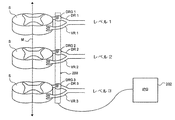
図6は、さまざまなレベル(階層、この具体例ではレベル1,2,3)にある脊髄Sを随意的に同時刺激することができるように構成された本発明に係る実施形態の装置200の構成を示すものである。装置200は、脊柱の正中線Mから所定の水平距離を隔てた位置の脊柱の硬膜上腔内に配置され、その正中線により、装置200が後根神経節DRG1,DRG2,DRG3に対して位置合わせされる。すなわち、装置200の複数の部分が後根神経節DRG1,DRG2,DRG3に位置合わせされ、任意的には、陰影を付したところで、これらと接触してもよい。これらの位置合わせされた部分により、1つまたはそれ以上の後根神経節DRG1,DRG2,DRG3について、標的とした刺激または選択した刺激が与えられ、前根VR1,VR2,VR3などの周辺組織に対する刺激を低減または回避することができる。
FIG. 6 illustrates an
装置200は、患者の体内に移植される電源または図示された移植可能なパルス発生器(IPG)202に電気的に接続されている。図6は、装置200の順行性配置構成を示すものであるが、後行性の手法も採用することができる。すなわち装置200は、IPG202への単一の延長部を有するか、または標的レベルの数より小さい任意の数の延長部を有する集合リードの形態で、複数のレベルにわたって延びる。
The
図7は、骨構造、すなわち脊髄Sを包囲し保護する脊椎骨Vを含む脊髄Sの側面図である。図示された装置200は、脊椎骨Vの椎孔を貫通して長手方向に延びる。任意であるが、移動しないようにするため、図示のように骨ねじまたは骨鋲などの固定手段204を用いて、装置200を脊椎骨Vに固定してもよい。図8は、図7の装置200の断面図であり、装置200がDRGに対して配置されている様子を示す。装置200は、長手方向の配向を維持しつつ、DRGに隣接または近接したさまざまな位置に配置することができる。
FIG. 7 is a side view of the spinal cord S including the bone structure, ie, the vertebra V surrounding and protecting the spinal cord S. FIG. The illustrated
図9A〜図9Cは、本発明に係る実施形態による装置200を示し、この装置は、さまざまな間隔で配置された複数の電極210を有し、そして/または活性電極間の間隔を調節することができる。図9Aは、表面上に少なくとも2つの電極210を含む長い本体部201を有する。長い本体部201は長手方向軸203を有し、この実施形態において、少なくとも2つの電極210が長手方向軸203に沿って配置されている。少なくとも2つの電極210は、(平均的な患者の母集団または特定の生体構造に基づいて)脊髄レベル間の距離または脊柱に沿ったDRG間の長手方向の距離に応じた長手方向軸203に沿った一定間隔を有する。距離Xおよび距離Yは、少なくとも2つの電極210の間の距離を示す。距離Xおよび距離Yは、同一でもよく、互いに異なっていてもよい。電極210が標的とするDRGの範囲内に収まるように、この距離が選択され、各電極210は、DRGを選択的に刺激することができるような距離内に配置される。
9A-9C illustrate a
図9Bは、表面上に複数の電極210を含む長い本体部201を有する装置200の実施形態を示すものである。2つまたはそれ以上の電極210は、離間距離を隔てた位置に集合して配置される。たとえば図9Bは、長い本体部201の遠位端付近に配設された電極210aの第1の集合体と、長い本体部201に沿って中間部に配設された電極210bの第2の集合体と、長い本体部201の近位端付近に配設された電極210cの第3の集合体とを有する。この具体例では、各集合体210a,210b,210cは、長手方向軸203に沿って3つずつの電極を有する。長い本体部201が解剖学的範囲に配置されるとき、DRG間の距離に解剖学的な変動が生じる場合がある。したがって、各集合体210a,210b,210c内の電極210のうち、(陰影を付したように)標的とするDRGに最も適確に位置合わせされた、または最も好適な治療的効果が得られた集合体内の電極210を用いてもよい。集合体内の残りの2つの電極には刺激エネルギが供給されない。いくつかの実施形態において、各集合体内の2つ以上の電極210を用いると、より好ましい結果が得られる場合には、2つ以上の電極を用いてもよい。刺激電極間の距離Xおよび距離Yを変えて、個々の患者に対する異なるDRG間隔に対応することができる。さらに装置200が長時間において変位した(すれた)とき、または最適な効能が得られたときに比して効果が薄れたとき、長い本体部201の位置を変えずに、電気エネルギを供給する電極210を変更することができる。こうして、距離Xおよび距離Yを調整することにより、電極をDRGに位置合わせし直すことができる。
FIG. 9B shows an embodiment of an
図9Cは、装置200の実施形態を示し、この装置200は、長手方向軸203に沿って表面上に配置された複数の電極を含む長い本体部201を有する。この実施形態では、複数の電極210が装置200に沿って実質的に連続的に配置されている。これらの電極は(陰影を付したように)選択的に用いられ、距離Xおよび距離Yを調節して、個々の患者に対する異なるDRG間隔に対応することができる。任意の数の電極を任意の構成で設けてもよい。また任意の数の間隔を設けて、距離X、距離Yおよび距離Zを形成することができる。
FIG. 9C shows an embodiment of the
図10A〜図10Cは、集合リード装置200の実施形態を示し、この装置は、複数の電極の位置を調節することができる伸縮自在の(telescoping:入れ子式の)シャフト220を有する。この実施形態において、伸縮自在シャフト220は、第1の構造体または管状本体部220aと、第2の構造体または管状本体部220bとを有する。第1の管状本体部220aおよび第2の管状本体部220bのそれぞれは、近位端、遠位端、およびその間に延びる内腔部を有する。第1および第2の管状本体部220a,220bは、同様に、表面上であって、好適には遠位端付近に少なくとも1つの電極を有する。この実施形態において、第2の長い管状本体部の遠位端およびその上の電極210が第1の長い管状本体部220aの遠位端を越えて延びるように、第2の長い管状本体部は、第1の長い管状本体部220aの中を並進移動できる。また、シャフト220は、遠位端を含む内側構造体220cを有し、この内側構造体は、その遠位端が第2の長い管状本体部の遠位端を越えて延びるように、第2の長い管状本体部220bの中を並進移動することができる。内側構造体220cは、同様に、表面上に少なくとも1つの電極210を有し、この電極が第2の長い管状本体部220bの遠位端を越えて露出する。すなわち、3つの電極210は、同時に露出し、組織を刺激するために用いることができる。電極間の距離Xおよび距離Yは、管状本体部220a,220bおよび内側構造体220cを互いに対して伸張または収縮させることにより移動させることにより調節することができる。
10A-10C show an embodiment of a
伸縮自在の構造体220a,220b,220cは、さまざまな材料を用いて、好適には可撓性を有するポリマを用いて形成することができる。いくつかの実施形態では、内側構造体220cは、装置200の孔内移動を押し進めるのに十分な強度を有するように、近位端および遠位端の間に延びる強化部材を有する。任意ではあるが、配置の際、構造体220a,220b,220cをスタイレットで支持してもよい。伸縮自在の構造体220a,220b,220cは、回転することを防止するようなさまざまな断面形状を有していてもよい。図10Bは、回転防止形状の具体例としての扁平形状を示すが、楕円形状や長方形、矩形、多角形などであってもよい。平坦な形状により、たとえば内側構造体220cが第2の長い管状本体部220b内で回転すること、または第2の長い管状本体部220bが第1の長い管状本体部220a内で回転することを防止することができる。このように回転を防止することにより、電極の長手方向の位置合わせに際して、複数の電極の回転方向の向きを互いに対して一定に維持することができる。択一的には、円形、正方形、矩形、多角形などの断面形状を厚くしてもよい(図10C)。円形形状である場合には、電極の回転方向の向きを調節することができる。
The
電極210は、平坦な設計への固定や、エネルギの節約等がより容易である場合がある。上述のように、平坦に設計すると、電極210の送達および移植の際、電極の向きを決定しやすくなる場合がある。断面形状も同様に、装置が配置される解剖学上の位置に基づいて選択してもよい。図11は、電極210が複数の脊髄レベル上のDRGに隣接するように硬膜上腔内に配置された伸縮自在シャフト220を図示する。これは、電極210がDRGに実質的に位置合わせされるように、伸縮自在の構造体220a,220b,220cを伸張または収縮させることにより実現することができる。電極210に電気的に接続された導電性ワイヤは、近位端から外部へパルス発生器(IPG)に延びている。
The
上述の実施形態においては、他の生体組織に対する不要な刺激を与えることを極力抑え、または回避しつつ、後根、とりわけ後根神経節(DRG)を直接的に刺激する装置、システムおよび方法について説明してきた。いくつかの実施形態において、これは、単一の装置を用いて、脊柱の複数レベルにアクセスすることを可能にするものである。これは、脊柱の各レベルに個別のアクセス経路を設けるのではなく、単一の経路を形成するため、施術上の煩雑性、所用時間、および回復を低減するものである。また、これらの実施形態は、パルス発生器(IPG)に至る経路の数を低減するものである。本発明に係る装置、システムおよび方法を用いて、他の脊髄組織の部位または他の生体組織を刺激することができる。 In the above-described embodiment, an apparatus, system, and method for directly stimulating the dorsal root, particularly the dorsal root ganglion (DRG), while minimizing or avoiding applying unnecessary stimulation to other living tissues. I have explained. In some embodiments, this allows access to multiple levels of the spinal column using a single device. This creates a single path rather than providing separate access paths at each level of the spinal column, thus reducing surgical complexity, time required, and recovery. These embodiments also reduce the number of paths to the pulse generator (IPG). The apparatus, system and method according to the present invention can be used to stimulate other spinal tissue sites or other biological tissues.
本発明に係る装置およびシステムを用いて、単一の後根神経節(DRG)を刺激することができる。たとえば図12は、図9Cの装置と同様または類似の装置を図示するが、装置200は、表面上に実質的に連続的に長手方向軸203に沿って配置された複数の電極210を含む長い本体部201を有する。装置200は硬膜上腔を通して移動させ、装置200の少なくとも一部は、単一の後根神経節(DRG)に向かって水平方向に移動する。いくつかの事例においては、これは孔を介して移動させる。複数の電極210のうちの少なくとも1つは、後根神経節の上、近傍、または周囲に配置されるように装置200を配設する。そして、もっとも好ましい結果をもたらす電極210に刺激エネルギが供給されるように、複数の電極を(陰影を付したように)選択的に用いる。それ以外の電極には、低レベルの刺激エネルギが供給されるか、または刺激エネルギがまったく供給されない。
Devices and systems according to the present invention can be used to stimulate a single dorsal root ganglion (DRG). For example, FIG. 12 illustrates an apparatus similar or similar to the apparatus of FIG. 9C, but the
また図13は、図10Aの装置と同様または類似の伸縮自在シャフト220を有する装置200を図示する。同様に、伸縮自在シャフト220は、第1の構造体または長い管状本体部220aと、第2の構造体または長い管状本体部220bとを有する。管状本体部220a,220bのそれぞれは、近位端、遠位端、およびこれらの間に延びるルーメンを有する。また各管状本体部220a,220bは、その表面上に配置された少なくとも1つの電極を有する。この実施形態では、第2の長い管状本体部220bの遠位端およびその上にある電極210が第1の長い管状本体部220aの遠位端を越えて延びるように、第2の長い管状本体部220bは、第1の長い管状本体部220aのルーメン内を移動することができる。シャフト220は、遠位端を含む内側構造体220cを有し、内側構造体220cし、その遠位端が第2の長い管状本体部220bの遠位端を越えて延びるように、第2の長い管状本体部220bのルーメン内を移動することができる。内側構造体220cは、その表面上に少なくとも1つの電極210を有し、その電極210は第2の長い管状本体部220bの遠位端を越えて延びるものである。すなわち3つすべての電極210は、同時に露出し、組織を刺激するために用いることができる。
FIG. 13 also illustrates a
図13は、脊柱の外部から水平方向に個別の後根神経節(DRG)に接近する装置200を図示する。少なくとも1つの電極20が後根神経節の上、近傍、または周囲に配置されるように、1つまたはそれ以上の第1の長い管状本体部220a、第2の長い管状本体部220b、および内側構造体220cが伸張または収縮することができる。そして、もっとも好ましい結果をもたらす電極210に刺激エネルギが供給されるように、複数の電極を(陰影を付したように)選択的に用いる。
FIG. 13 illustrates a
本発明について、明確に理解されるように図面および実施例を用いて、これまで詳細に説明してきたが、さまざまな変形例、変更例、および均等物を採用できることは明白であり、上記記載事項は本発明の範囲を限定するものとして解釈すべきではない。 Although the invention has been described in detail with reference to the drawings and examples for clarity of understanding, it will be apparent that various modifications, changes and equivalents may be employed. Should not be construed as limiting the scope of the invention.
10:脊髄電気刺激(SCS)システム、12,202:パルス発生器(IPG)、14:リード、16:パドルリード、17:上行経路、18:経皮リード、19:下行経路、20:電極、200:装置、201:長い本体部、203:長手方向軸、204:固定手段、210:電極、220:伸縮自在シャフト、220a:第1の構造体または管状本体部、220b:第2の構造体または管状本体部、220c:内側構造体、N:末梢神経、S:脊髄、E:硬膜上腔、D:脊柱硬膜、VR:前根、DR:後根、V:脊椎骨、DRG:後根神経節。 10: spinal cord electrical stimulation (SCS) system, 12, 202: pulse generator (IPG), 14: lead, 16: paddle lead, 17: ascending route, 18: percutaneous lead, 19: descending route, 20: electrode, 200: device, 201: long body, 203: longitudinal axis, 204: fixing means, 210: electrode, 220: telescopic shaft, 220a: first structure or tubular body, 220b: second structure Or tubular body part, 220c: inner structure, N: peripheral nerve, S: spinal cord, E: epidural space, D: spinal dura mater, VR: anterior root, DR: dorsal root, V: vertebra, DRG: posterior Root ganglion.
Claims (16)
表面上に複数の電極を有する長い本体部を有するリードであって、本体部の少なくとも一部が硬膜上腔内に配置され、前記複数の電極が後根神経節から所定距離の範囲内に配置されるように構成されたリードと、
リードに接続可能であり、後根神経節以外の組織に対し不要な刺激を与えることなく、後根神経節に対し選択的に刺激を与えることにより、最も良好な効果が得られるように選択された複数の電極に刺激エネルギを与えるための移植可能なパルス発生器とを備え、
パルス発生器は、複数の電極のうちの第1の部位にある第1の電極から刺激エネルギを与え、複数の電極のうちの第2の部位にある第2の電極から刺激エネルギを与え、
第1および第2の電極は、本体部に沿って長手方向に配置され、第1および第2の部位の間の長手方向の距離が調整可能であることを特徴とするシステム。 A system for stimulating the dorsal root ganglia in the body,
A lead having a long body portion having a plurality of electrodes on the surface , wherein at least a part of the body portion is disposed in the epidural space, and the plurality of electrodes are within a predetermined distance from the dorsal root ganglion. A lead configured to be disposed;
It can be connected to the lead and selected to give the best effect by selectively stimulating dorsal root ganglia without causing unnecessary stimulation to tissues other than dorsal root ganglia. An implantable pulse generator for providing stimulation energy to a plurality of electrodes,
The pulse generator provides stimulation energy from a first electrode at a first part of the plurality of electrodes, and applies stimulation energy from a second electrode at a second part of the plurality of electrodes,
The system is characterized in that the first and second electrodes are arranged in the longitudinal direction along the main body, and the longitudinal distance between the first and second parts is adjustable.
複数の電極のうちの異なる電極に刺激エネルギを与えることにより、第1および第2の部位の間の長手方向の距離を調整可能にすることを特徴とするシステム。 The system of claim 1, comprising:
A system characterized in that the longitudinal distance between the first and second sites is adjustable by applying stimulation energy to different ones of the plurality of electrodes.
第1の電極を後根神経節の第1の部位に位置合わせし、第2の電極を後根神経節の第2の部位に位置合わせするように、第1および第2の部位の間の長手方向の距離を調整可能とすることを特徴とするシステム。 The system of claim 2, comprising:
Between the first and second sites such that the first electrode is aligned with the first site of the dorsal root ganglion and the second electrode is aligned with the second site of the dorsal root ganglion. A system characterized in that the longitudinal distance is adjustable.
第1および第2の電極の間に別の電極が配置され、第1および第2の電極に刺激エネルギを与えるときに、別の電極には刺激エネルギを与えられないことを特徴とするシステム。 The system of claim 2, comprising:
A system in which another electrode is disposed between the first and second electrodes, and when the stimulation energy is applied to the first and second electrodes, the stimulation energy cannot be applied to the other electrode.
第1および第2の部位の間の長手方向の距離は、第1および第2の電極を互いに対して物理的に移動させることにより調整可能であることを特徴とするシステム。 The system of claim 1, comprising:
A system wherein the longitudinal distance between the first and second sites is adjustable by physically moving the first and second electrodes relative to each other.
複数の電極には個別にエネルギを供給することができることを特徴とするシステム。 The system of claim 1, comprising:
A system characterized in that energy can be supplied to a plurality of electrodes individually.
後根神経節への選択的刺激による最も良好な効果が得られない1つまたはそれ以上の電極には刺激エネルギを与えないことを特徴とするシステム。 The system of claim 1, comprising:
A system wherein no stimulation energy is applied to one or more electrodes that do not provide the best effect of selective stimulation to the dorsal root ganglion.
後根神経節への選択的刺激による最も良好な効果が得られない1つまたはそれ以上の電極には、後根神経節への選択的刺激による最も良好な効果が得られる電極より小さい刺激エネルギを与えることを特徴とするシステム。 The system of claim 1, comprising:
One or more electrodes that do not provide the best effect due to selective stimulation to the dorsal root ganglion include a stimulation energy that is less than the electrode that provides the best effect due to selective stimulation to the dorsal root ganglion. A system characterized by giving.
リードは、体内の硬膜上腔を貫通して移動できるような寸法を有することを特徴とするシステム。 The system of claim 1, comprising:
A system wherein the lead is sized to move through the epidural space in the body.
リードは、後根神経節に向かって水平方向に移動できるような寸法を有することを特徴とするシステム。 The system of claim 1, comprising:
The lead is sized so that it can move horizontally toward the dorsal root ganglion.
リードは、孔を貫通して移動するような寸法を有することを特徴とするシステム。 The system of claim 1, comprising:
A system wherein the lead is dimensioned to move through the hole.
リードは、伸縮自在のリードであることを特徴とするシステム。 The system of claim 1, comprising:
The system is characterized in that the lead is a retractable lead.
伸縮自在のリードは、長い管状本体部と、内側構造体とを有し、
管状本体部は、近位端、遠位端、これらの間のルーメン、および表面上に配置された少なくとも1つの電極を有し、
内側構造体は、近位端、遠位端、および表面上に配置された少なくとも1つの電極を有し、内側構造体の遠位端が管状本体部の遠位端を越えて延びるように、管状本体部のルーメンを貫通して移動することを特徴とするシステム。 The system of claim 12, comprising:
The telescopic lead has a long tubular body and an inner structure,
The tubular body has a proximal end, a distal end, a lumen therebetween, and at least one electrode disposed on the surface;
The inner structure has a proximal end, a distal end, and at least one electrode disposed on the surface, such that the distal end of the inner structure extends beyond the distal end of the tubular body portion. A system that moves through the lumen of the tubular body.
内側構造体は、伸張または収縮可能であり、内側構造体の上に配置された電極と管状本体部の上に配置された電極との間の距離を調節することができることを特徴とするシステム。 14. The system according to claim 13, wherein
The system wherein the inner structure is stretchable or contractible and the distance between the electrode disposed on the inner structure and the electrode disposed on the tubular body can be adjusted.
管状本体部上の少なくとも1つの電極が後根神経節の第1部分に位置合わせされ、内側構造体上の少なくとも1つの電極が後根神経節の第2部分に位置合わせされるように、内側構造体の上に配置された電極と管状本体部の上に配置された電極との間の距離を調節することができることを特徴とするシステム。 15. The system according to claim 14, wherein
Medial such that at least one electrode on the tubular body is aligned with the first portion of the dorsal root ganglion and at least one electrode on the inner structure is aligned with the second portion of the dorsal root ganglion A system characterized in that the distance between an electrode arranged on the structure and an electrode arranged on the tubular body can be adjusted.
内側構造体が管状本体部のルーメン内で回転するのを防止するような形状を有するか、あるいは管状本体部が内側構造体の周囲で回転するのを防止するような形状を有することを特徴とするシステム。 14. The system according to claim 13, wherein
It has a shape that prevents the inner structure from rotating within the lumen of the tubular body, or a shape that prevents the tubular body from rotating around the inner structure. System.
Applications Claiming Priority (3)
| Application Number | Priority Date | Filing Date | Title |
|---|---|---|---|
| US87346406P | 2006-12-06 | 2006-12-06 | |
| US60/873,464 | 2006-12-06 | ||
| PCT/US2007/086693 WO2008070804A2 (en) | 2006-12-06 | 2007-12-06 | Grouped leads for spinal stimulation |
Related Child Applications (1)
| Application Number | Title | Priority Date | Filing Date |
|---|---|---|---|
| JP2013166689A Division JP5759519B2 (en) | 2006-12-06 | 2013-08-09 | Collective lead for spinal cord stimulation |
Publications (3)
| Publication Number | Publication Date |
|---|---|
| JP2010512185A JP2010512185A (en) | 2010-04-22 |
| JP2010512185A5 JP2010512185A5 (en) | 2011-01-20 |
| JP5433420B2 true JP5433420B2 (en) | 2014-03-05 |
Family
ID=39493080
Family Applications (2)
| Application Number | Title | Priority Date | Filing Date |
|---|---|---|---|
| JP2009540485A Expired - Fee Related JP5433420B2 (en) | 2006-12-06 | 2007-12-06 | Collective lead for spinal cord stimulation |
| JP2013166689A Active JP5759519B2 (en) | 2006-12-06 | 2013-08-09 | Collective lead for spinal cord stimulation |
Family Applications After (1)
| Application Number | Title | Priority Date | Filing Date |
|---|---|---|---|
| JP2013166689A Active JP5759519B2 (en) | 2006-12-06 | 2013-08-09 | Collective lead for spinal cord stimulation |
Country Status (7)
| Country | Link |
|---|---|
| US (1) | US20080147156A1 (en) |
| EP (1) | EP2094350B1 (en) |
| JP (2) | JP5433420B2 (en) |
| CN (1) | CN101588839A (en) |
| AU (1) | AU2007329250B2 (en) |
| CA (1) | CA2671575A1 (en) |
| WO (1) | WO2008070804A2 (en) |
Families Citing this family (37)
| Publication number | Priority date | Publication date | Assignee | Title |
|---|---|---|---|---|
| US8082039B2 (en) | 2004-09-08 | 2011-12-20 | Spinal Modulation, Inc. | Stimulation systems |
| US20120277839A1 (en) | 2004-09-08 | 2012-11-01 | Kramer Jeffery M | Selective stimulation to modulate the sympathetic nervous system |
| US9205261B2 (en) | 2004-09-08 | 2015-12-08 | The Board Of Trustees Of The Leland Stanford Junior University | Neurostimulation methods and systems |
| WO2008070806A2 (en) | 2006-12-06 | 2008-06-12 | Spinal Modulation, Inc. | Hard tissue anchors and delivery devices |
| WO2008070807A2 (en) | 2006-12-06 | 2008-06-12 | Spinal Modulation, Inc. | Delivery devices, systems and methods for stimulating nerve tissue on multiple spinal levels |
| US9072897B2 (en) | 2007-03-09 | 2015-07-07 | Mainstay Medical Limited | Systems and methods for restoring muscle function to the lumbar spine |
| US11331488B2 (en) | 2007-03-09 | 2022-05-17 | Mainstay Medical Limited | Systems and methods for enhancing function of spine stabilization muscles associated with a spine surgery intervention |
| US11679262B2 (en) | 2007-03-09 | 2023-06-20 | Mainstay Medical Limited | Systems and methods for restoring muscle function to the lumbar spine |
| ES2827186T3 (en) * | 2007-03-09 | 2021-05-20 | Mainstay Medical Ltd | Neuromuscular electrical stimulation system |
| US11679261B2 (en) | 2007-03-09 | 2023-06-20 | Mainstay Medical Limited | Systems and methods for enhancing function of spine stabilization muscles associated with a spine surgery intervention |
| BRPI0817544A2 (en) | 2007-10-10 | 2017-05-02 | Univ Wake Forest Health Sciences | apparatus for treating damaged spinal cord tissue |
| CN102202729B (en) | 2008-10-27 | 2014-11-05 | 脊髓调制公司 | Selective stimulation systems and signal parameters for medical conditions |
| EP2346567A4 (en) * | 2008-11-13 | 2012-04-25 | Proteus Biomedical Inc | Multiplexed multi-electrode neurostimulation devices |
| WO2010057063A2 (en) * | 2008-11-13 | 2010-05-20 | Proteus Biomedical, Inc. | Pacing and stimulation system, device and method |
| EP2349466A4 (en) | 2008-11-13 | 2013-03-20 | Proteus Digital Health Inc | Shielded stimulation and sensing system and method |
| US20100228310A1 (en) * | 2009-03-09 | 2010-09-09 | Shuros Allan C | Systems and methods for autonomic nerve modulation |
| CN102438698B (en) | 2009-03-24 | 2014-09-10 | 脊髓调制公司 | Pain management with stimulation subthreshold to parasthesia |
| WO2010132816A2 (en) | 2009-05-15 | 2010-11-18 | Spinal Modulation, Inc. | Methods, systems and devices for neuromodulating spinal anatomy |
| US9327110B2 (en) | 2009-10-27 | 2016-05-03 | St. Jude Medical Luxembourg Holdings SMI S.A.R.L. (“SJM LUX SMI”) | Devices, systems and methods for the targeted treatment of movement disorders |
| US11786725B2 (en) | 2012-06-13 | 2023-10-17 | Mainstay Medical Limited | Systems and methods for restoring muscle function to the lumbar spine and kits for implanting the same |
| US9950159B2 (en) | 2013-10-23 | 2018-04-24 | Mainstay Medical Limited | Systems and methods for restoring muscle function to the lumbar spine and kits for implanting the same |
| US11684774B2 (en) | 2010-03-11 | 2023-06-27 | Mainstay Medical Limited | Electrical stimulator for treatment of back pain and methods of use |
| CN103079633B (en) | 2010-03-11 | 2016-05-04 | 梅恩斯塔伊医疗公司 | Be used for the treatment of modular stimulator, implanted RF ablation system and the using method of backache |
| EP2568904B1 (en) | 2010-05-10 | 2019-10-02 | Spinal Modulation Inc. | Device for reducing migration |
| WO2013112920A1 (en) | 2012-01-25 | 2013-08-01 | Nevro Corporation | Lead anchors and associated systems and methods |
| CA2870052A1 (en) * | 2012-04-12 | 2013-10-17 | Wake Forest University Health Sciences | Design of a conduit for peripheral nerve replacement |
| US20130317587A1 (en) * | 2012-05-25 | 2013-11-28 | Boston Scientific Neuromodulation Corporation | Methods for stimulating the dorsal root ganglion with a lead having segmented electrodes |
| US10219895B2 (en) | 2012-10-26 | 2019-03-05 | Wake Forest University Health Sciences | Nanofiber-based graft for heart valve replacement and methods of using the same |
| US9265935B2 (en) | 2013-06-28 | 2016-02-23 | Nevro Corporation | Neurological stimulation lead anchors and associated systems and methods |
| US9511230B2 (en) | 2013-11-08 | 2016-12-06 | Nuvectra Corporation | Implantable medical lead for stimulation of multiple nerves |
| US9643003B2 (en) | 2014-11-10 | 2017-05-09 | Steven Sounyoung Yu | Craniofacial neurostimulation for treatment of pain conditions |
| EP3256206A1 (en) * | 2015-02-09 | 2017-12-20 | Boston Scientific Neuromodulation Corporation | System for determining neurological position of epidural leads |
| US10376702B2 (en) * | 2016-04-04 | 2019-08-13 | Boston Scientific Neuromodulation Corporation | System to estimate the location of a spinal cord physiological midline |
| US10327810B2 (en) | 2016-07-05 | 2019-06-25 | Mainstay Medical Limited | Systems and methods for enhanced implantation of electrode leads between tissue layers |
| CN109999341A (en) * | 2018-01-04 | 2019-07-12 | 精能医学股份有限公司 | Egersimeter, the method and electric stimulation for manufacturing egersimeter |
| CN110013605A (en) * | 2018-01-10 | 2019-07-16 | 精能医学股份有限公司 | Egersimeter, treatment method and electric stimulation |
| US10933234B2 (en) * | 2018-05-11 | 2021-03-02 | Synerfuse, Inc. | System, devices, and methods combining spinal stabilization and neuromodulation |
Family Cites Families (97)
| Publication number | Priority date | Publication date | Assignee | Title |
|---|---|---|---|---|
| US3724467A (en) * | 1971-04-23 | 1973-04-03 | Avery Labor Inc | Electrode implant for the neuro-stimulation of the spinal cord |
| US4141367A (en) * | 1977-04-29 | 1979-02-27 | Med Telectronics Ltd. | Cardiac electrode/pacer system analyzer |
| US4374527A (en) * | 1978-07-19 | 1983-02-22 | Medtronic, Inc. | Body stimulation lead |
| US4739764A (en) * | 1984-05-18 | 1988-04-26 | The Regents Of The University Of California | Method for stimulating pelvic floor muscles for regulating pelvic viscera |
| US4590946A (en) * | 1984-06-14 | 1986-05-27 | Biomed Concepts, Inc. | Surgically implantable electrode for nerve bundles |
| US4573481A (en) * | 1984-06-25 | 1986-03-04 | Huntington Institute Of Applied Research | Implantable electrode array |
| US4640286A (en) * | 1984-11-02 | 1987-02-03 | Staodynamics, Inc. | Optimized nerve fiber stimulation |
| US4577642A (en) * | 1985-02-27 | 1986-03-25 | Medtronic, Inc. | Drug dispensing body implantable lead employing molecular sieves and methods of fabrication |
| US4920979A (en) * | 1988-10-12 | 1990-05-01 | Huntington Medical Research Institute | Bidirectional helical electrode for nerve stimulation |
| US5299569A (en) * | 1991-05-03 | 1994-04-05 | Cyberonics, Inc. | Treatment of neuropsychiatric disorders by nerve stimulation |
| US5792187A (en) * | 1993-02-22 | 1998-08-11 | Angeion Corporation | Neuro-stimulation to control pain during cardioversion defibrillation |
| US5411540A (en) * | 1993-06-03 | 1995-05-02 | Massachusetts Institute Of Technology | Method and apparatus for preferential neuron stimulation |
| US5417719A (en) * | 1993-08-25 | 1995-05-23 | Medtronic, Inc. | Method of using a spinal cord stimulation lead |
| US5411537A (en) * | 1993-10-29 | 1995-05-02 | Intermedics, Inc. | Rechargeable biomedical battery powered devices with recharging and control system therefor |
| US5489294A (en) * | 1994-02-01 | 1996-02-06 | Medtronic, Inc. | Steroid eluting stitch-in chronic cardiac lead |
| SE9401267D0 (en) * | 1994-04-14 | 1994-04-14 | Siemens Elema Ab | The electrode device |
| US5505201A (en) * | 1994-04-20 | 1996-04-09 | Case Western Reserve University | Implantable helical spiral cuff electrode |
| US5514175A (en) * | 1994-11-09 | 1996-05-07 | Cerebral Stimulation, Inc. | Auricular electrical stimulator |
| US5741319A (en) * | 1995-01-27 | 1998-04-21 | Medtronic, Inc. | Biocompatible medical lead |
| US5733322A (en) * | 1995-05-23 | 1998-03-31 | Medtronic, Inc. | Positive fixation percutaneous epidural neurostimulation lead |
| US5755750A (en) * | 1995-11-13 | 1998-05-26 | University Of Florida | Method and apparatus for selectively inhibiting activity in nerve fibers |
| ATE375070T1 (en) * | 1996-01-31 | 2007-10-15 | Cochlear Ltd | THIN FILM PRODUCTION TECHNOLOGY FOR IMPLANTABLE ELECTRODES |
| WO1997029802A2 (en) * | 1996-02-20 | 1997-08-21 | Advanced Bionics Corporation | Improved implantable microstimulator and systems employing the same |
| US5713922A (en) * | 1996-04-25 | 1998-02-03 | Medtronic, Inc. | Techniques for adjusting the locus of excitation of neural tissue in the spinal cord or brain |
| US5711316A (en) * | 1996-04-30 | 1998-01-27 | Medtronic, Inc. | Method of treating movement disorders by brain infusion |
| US5885290A (en) * | 1996-12-09 | 1999-03-23 | Guerrero; Cesar A. | Intra-oral bone distraction device |
| US5865843A (en) * | 1997-04-23 | 1999-02-02 | Medtronic Inc. | Medical neurological lead with integral fixation mechanism |
| US6839588B1 (en) * | 1997-07-31 | 2005-01-04 | Case Western Reserve University | Electrophysiological cardiac mapping system based on a non-contact non-expandable miniature multi-electrode catheter and method therefor |
| US5871531A (en) * | 1997-09-25 | 1999-02-16 | Medtronic, Inc. | Medical electrical lead having tapered spiral fixation |
| US6045532A (en) * | 1998-02-20 | 2000-04-04 | Arthrocare Corporation | Systems and methods for electrosurgical treatment of tissue in the brain and spinal cord |
| US6319241B1 (en) * | 1998-04-30 | 2001-11-20 | Medtronic, Inc. | Techniques for positioning therapy delivery elements within a spinal cord or a brain |
| US6161047A (en) * | 1998-04-30 | 2000-12-12 | Medtronic Inc. | Apparatus and method for expanding a stimulation lead body in situ |
| US7599736B2 (en) * | 2001-07-23 | 2009-10-06 | Dilorenzo Biomedical, Llc | Method and apparatus for neuromodulation and physiologic modulation for the treatment of metabolic and neuropsychiatric disease |
| US6044297A (en) * | 1998-09-25 | 2000-03-28 | Medtronic, Inc. | Posture and device orientation and calibration for implantable medical devices |
| US6208902B1 (en) * | 1998-10-26 | 2001-03-27 | Birinder Bob Boveja | Apparatus and method for adjunct (add-on) therapy for pain syndromes utilizing an implantable lead and an external stimulator |
| US6366814B1 (en) * | 1998-10-26 | 2002-04-02 | Birinder R. Boveja | External stimulator for adjunct (add-on) treatment for neurological, neuropsychiatric, and urological disorders |
| US6393325B1 (en) * | 1999-01-07 | 2002-05-21 | Advanced Bionics Corporation | Directional programming for implantable electrode arrays |
| US6436099B1 (en) * | 1999-04-23 | 2002-08-20 | Sdgi Holdings, Inc. | Adjustable spinal tether |
| US6055456A (en) * | 1999-04-29 | 2000-04-25 | Medtronic, Inc. | Single and multi-polar implantable lead for sacral nerve electrical stimulation |
| US6214016B1 (en) * | 1999-04-29 | 2001-04-10 | Medtronic, Inc. | Medical instrument positioning device internal to a catheter or lead and method of use |
| US6353762B1 (en) * | 1999-04-30 | 2002-03-05 | Medtronic, Inc. | Techniques for selective activation of neurons in the brain, spinal cord parenchyma or peripheral nerve |
| US6516227B1 (en) * | 1999-07-27 | 2003-02-04 | Advanced Bionics Corporation | Rechargeable spinal cord stimulator system |
| US6517542B1 (en) * | 1999-08-04 | 2003-02-11 | The Cleveland Clinic Foundation | Bone anchoring system |
| US7047082B1 (en) * | 1999-09-16 | 2006-05-16 | Micronet Medical, Inc. | Neurostimulating lead |
| US6356786B1 (en) * | 2000-01-20 | 2002-03-12 | Electrocore Techniques, Llc | Method of treating palmar hyperhydrosis by electrical stimulation of the sympathetic nervous chain |
| US7181289B2 (en) * | 2000-03-20 | 2007-02-20 | Pflueger D Russell | Epidural nerve root access catheter and treatment methods |
| US6510347B2 (en) * | 2000-08-17 | 2003-01-21 | William N. Borkan | Spinal cord stimulation leads |
| US6871099B1 (en) * | 2000-08-18 | 2005-03-22 | Advanced Bionics Corporation | Fully implantable microstimulator for spinal cord stimulation as a therapy for chronic pain |
| US6862479B1 (en) * | 2000-08-30 | 2005-03-01 | Advanced Bionics Corporation | Spinal cord stimulation as a therapy for sexual dysfunction |
| US7043299B2 (en) * | 2000-09-18 | 2006-05-09 | Cameron Health, Inc. | Subcutaneous implantable cardioverter-defibrillator employing a telescoping lead |
| US6522926B1 (en) * | 2000-09-27 | 2003-02-18 | Cvrx, Inc. | Devices and methods for cardiovascular reflex control |
| US6901287B2 (en) * | 2001-02-09 | 2005-05-31 | Medtronic, Inc. | Implantable therapy delivery element adjustable anchor |
| US6873342B2 (en) * | 2001-04-12 | 2005-03-29 | Mitsubishi Electric Research Laboratories, Inc. | Method for generating detail directed visibility elements for a graphics model |
| US6892098B2 (en) * | 2001-04-26 | 2005-05-10 | Biocontrol Medical Ltd. | Nerve stimulation for treating spasticity, tremor, muscle weakness, and other motor disorders |
| US6512958B1 (en) * | 2001-04-26 | 2003-01-28 | Medtronic, Inc. | Percutaneous medical probe and flexible guide wire |
| US6554809B2 (en) * | 2001-08-02 | 2003-04-29 | Teodulo Aves | Epidural catheter needle |
| US6535767B1 (en) * | 2001-08-21 | 2003-03-18 | James W. Kronberg | Apparatus and method for bioelectric stimulation, healing acceleration and pain relief |
| US20030069569A1 (en) * | 2001-08-29 | 2003-04-10 | Burdette Everette C. | Ultrasound device for treatment of intervertebral disc tissue |
| US6999819B2 (en) * | 2001-08-31 | 2006-02-14 | Medtronic, Inc. | Implantable medical electrical stimulation lead fixation method and apparatus |
| AU2002334749A1 (en) * | 2001-09-28 | 2003-04-07 | Northstar Neuroscience, Inc. | Methods and implantable apparatus for electrical therapy |
| US6745079B2 (en) * | 2001-11-07 | 2004-06-01 | Medtronic, Inc. | Electrical tissue stimulation apparatus and method |
| AUPS101502A0 (en) * | 2002-03-11 | 2002-04-11 | Neopraxis Pty Ltd | Wireless fes system |
| US7146222B2 (en) * | 2002-04-15 | 2006-12-05 | Neurospace, Inc. | Reinforced sensing and stimulation leads and use in detection systems |
| US20040015202A1 (en) * | 2002-06-14 | 2004-01-22 | Chandler Gilbert S. | Combination epidural infusion/stimulation method and system |
| WO2004007018A1 (en) * | 2002-07-17 | 2004-01-22 | Remidi (Uk) Limited | Apparatus for the application of electrical pulses to the human body |
| US7993351B2 (en) * | 2002-07-24 | 2011-08-09 | Pressure Products Medical Supplies, Inc. | Telescopic introducer with a compound curvature for inducing alignment and method of using the same |
| US7107105B2 (en) * | 2002-09-24 | 2006-09-12 | Medtronic, Inc. | Deployable medical lead fixation system and method |
| US7069083B2 (en) * | 2002-12-13 | 2006-06-27 | Advanced Neuromodulation Systems, Inc. | System and method for electrical stimulation of the intervertebral disc |
| US20050027338A1 (en) * | 2003-07-29 | 2005-02-03 | Advanced Neuromodulation Systems, Inc. | Stretchable lead body, method of manufacture, and system |
| US7794476B2 (en) * | 2003-08-08 | 2010-09-14 | Warsaw Orthopedic, Inc. | Implants formed of shape memory polymeric material for spinal fixation |
| US20050033393A1 (en) * | 2003-08-08 | 2005-02-10 | Advanced Neuromodulation Systems, Inc. | Apparatus and method for implanting an electrical stimulation system and a paddle style electrical stimulation lead |
| US20050038489A1 (en) * | 2003-08-14 | 2005-02-17 | Grill Warren M. | Electrode array for use in medical stimulation and methods thereof |
| US7930037B2 (en) * | 2003-09-30 | 2011-04-19 | Medtronic, Inc. | Field steerable electrical stimulation paddle, lead system, and medical device incorporating the same |
| US20050080325A1 (en) * | 2003-10-14 | 2005-04-14 | Advanced Neuromodulation Systems, Inc. | Low profile connector and system for implantable medical device |
| US7437197B2 (en) * | 2003-10-23 | 2008-10-14 | Medtronic, Inc. | Medical lead and manufacturing method therefor |
| US8260436B2 (en) * | 2003-10-31 | 2012-09-04 | Medtronic, Inc. | Implantable stimulation lead with fixation mechanism |
| US7174219B2 (en) * | 2004-03-30 | 2007-02-06 | Medtronic, Inc. | Lead electrode for use in an MRI-safe implantable medical device |
| US7585311B2 (en) * | 2004-06-02 | 2009-09-08 | Kfx Medical Corporation | System and method for attaching soft tissue to bone |
| US7395120B2 (en) * | 2004-08-13 | 2008-07-01 | The General Hospital Corporation | Telescoping, dual-site pacing lead |
| US20060041295A1 (en) * | 2004-08-17 | 2006-02-23 | Osypka Thomas P | Positive fixation percutaneous epidural neurostimulation lead |
| US8082039B2 (en) * | 2004-09-08 | 2011-12-20 | Spinal Modulation, Inc. | Stimulation systems |
| US7555343B2 (en) * | 2004-10-15 | 2009-06-30 | Baxano, Inc. | Devices and methods for selective surgical removal of tissue |
| US7734340B2 (en) * | 2004-10-21 | 2010-06-08 | Advanced Neuromodulation Systems, Inc. | Stimulation design for neuromodulation |
| US20060089696A1 (en) * | 2004-10-21 | 2006-04-27 | Medtronic, Inc. | Implantable medical lead with reinforced outer jacket |
| US20080009927A1 (en) * | 2005-01-11 | 2008-01-10 | Vilims Bradley D | Combination Electrical Stimulating and Infusion Medical Device and Method |
| US20060167525A1 (en) * | 2005-01-19 | 2006-07-27 | Medtronic, Inc. | Method of stimulating multiple sites |
| GB2423020A (en) * | 2005-02-14 | 2006-08-16 | Algotec Ltd | Percutaneous electrical stimulation probe for pain relief |
| US20070060954A1 (en) * | 2005-02-25 | 2007-03-15 | Tracy Cameron | Method of using spinal cord stimulation to treat neurological disorders or conditions |
| US20060206178A1 (en) * | 2005-03-11 | 2006-09-14 | Kim Daniel H | Percutaneous endoscopic access tools for the spinal epidural space and related methods of treatment |
| US7672727B2 (en) * | 2005-08-17 | 2010-03-02 | Enteromedics Inc. | Neural electrode treatment |
| US7979131B2 (en) * | 2006-01-26 | 2011-07-12 | Advanced Neuromodulation Systems, Inc. | Method of neurostimulation of distinct neural structures using single paddle lead to treat multiple pain locations and multi-column, multi-row paddle lead for such neurostimulation |
| US20080033431A1 (en) * | 2006-06-29 | 2008-02-07 | Searete Llc, A Limited Liability Corporation Of The State Of Delaware | Position augmenting mechanism |
| US20080039916A1 (en) * | 2006-08-08 | 2008-02-14 | Olivier Colliou | Distally distributed multi-electrode lead |
| US9643004B2 (en) * | 2006-10-31 | 2017-05-09 | Medtronic, Inc. | Implantable medical elongated member with adhesive elements |
| US20080103580A1 (en) * | 2006-10-31 | 2008-05-01 | Medtronic, Inc. | Implantable medical elongated member with dual purpose conduit |
| US20080103572A1 (en) * | 2006-10-31 | 2008-05-01 | Medtronic, Inc. | Implantable medical lead with threaded fixation |
| US7853303B2 (en) * | 2006-11-16 | 2010-12-14 | National Research Council Of Canada | Neurological probe and method of using same |
-
2007
- 2007-12-06 CA CA002671575A patent/CA2671575A1/en not_active Abandoned
- 2007-12-06 US US11/952,049 patent/US20080147156A1/en not_active Abandoned
- 2007-12-06 WO PCT/US2007/086693 patent/WO2008070804A2/en active Application Filing
- 2007-12-06 EP EP07865338.3A patent/EP2094350B1/en not_active Not-in-force
- 2007-12-06 JP JP2009540485A patent/JP5433420B2/en not_active Expired - Fee Related
- 2007-12-06 CN CNA2007800450872A patent/CN101588839A/en active Pending
- 2007-12-06 AU AU2007329250A patent/AU2007329250B2/en not_active Ceased
-
2013
- 2013-08-09 JP JP2013166689A patent/JP5759519B2/en active Active
Also Published As
| Publication number | Publication date |
|---|---|
| JP5759519B2 (en) | 2015-08-05 |
| US20080147156A1 (en) | 2008-06-19 |
| EP2094350B1 (en) | 2018-06-13 |
| WO2008070804A2 (en) | 2008-06-12 |
| CN101588839A (en) | 2009-11-25 |
| JP2010512185A (en) | 2010-04-22 |
| EP2094350A2 (en) | 2009-09-02 |
| JP2013240710A (en) | 2013-12-05 |
| AU2007329250B2 (en) | 2012-03-15 |
| AU2007329250A1 (en) | 2008-06-12 |
| WO2008070804A3 (en) | 2008-09-25 |
| CA2671575A1 (en) | 2008-06-12 |
| EP2094350A4 (en) | 2010-07-14 |
Similar Documents
| Publication | Publication Date | Title |
|---|---|---|
| JP5433420B2 (en) | Collective lead for spinal cord stimulation | |
| JP5414531B2 (en) | Delivery device and systems and methods for stimulating neural tissue at multiple spinal levels | |
| JP6018249B2 (en) | Management of pain with subthreshold stimuli for illusion | |
| US9427570B2 (en) | Expandable stimulation leads and methods of use | |
| US6319241B1 (en) | Techniques for positioning therapy delivery elements within a spinal cord or a brain | |
| US7486995B2 (en) | System and method for stimulation of a person's brain stem | |
| JP2012521801A5 (en) | ||
| US20090076444A1 (en) | Method and apparatus for securing a neuromodulation lead to nervous tissue or tissue surrounding the nervous system | |
| US20130274846A1 (en) | Methods, devices and systems for treating pain | |
| AU2014202705B2 (en) | Grouped leads for spinal stimulation | |
| AU2014201494B2 (en) | Delivery Devices, Systems and Methods for Stimulating Nerve Tissue on Multiple Spinal Levels | |
| AU2012203467B2 (en) | Grouped leads for spinal stimulation |
Legal Events
| Date | Code | Title | Description |
|---|---|---|---|
| A521 | Request for written amendment filed |
Free format text: JAPANESE INTERMEDIATE CODE: A523 Effective date: 20101125 |
|
| A621 | Written request for application examination |
Free format text: JAPANESE INTERMEDIATE CODE: A621 Effective date: 20101125 |
|
| A131 | Notification of reasons for refusal |
Free format text: JAPANESE INTERMEDIATE CODE: A131 Effective date: 20120807 |
|
| A601 | Written request for extension of time |
Free format text: JAPANESE INTERMEDIATE CODE: A601 Effective date: 20121106 |
|
| A602 | Written permission of extension of time |
Free format text: JAPANESE INTERMEDIATE CODE: A602 Effective date: 20121113 |
|
| A601 | Written request for extension of time |
Free format text: JAPANESE INTERMEDIATE CODE: A601 Effective date: 20121207 |
|
| A602 | Written permission of extension of time |
Free format text: JAPANESE INTERMEDIATE CODE: A602 Effective date: 20121214 |
|
| A601 | Written request for extension of time |
Free format text: JAPANESE INTERMEDIATE CODE: A601 Effective date: 20130107 |
|
| A602 | Written permission of extension of time |
Free format text: JAPANESE INTERMEDIATE CODE: A602 Effective date: 20130115 |
|
| A521 | Request for written amendment filed |
Free format text: JAPANESE INTERMEDIATE CODE: A523 Effective date: 20130207 |
|
| A02 | Decision of refusal |
Free format text: JAPANESE INTERMEDIATE CODE: A02 Effective date: 20130409 |
|
| A521 | Request for written amendment filed |
Free format text: JAPANESE INTERMEDIATE CODE: A523 Effective date: 20130809 |
|
| A911 | Transfer to examiner for re-examination before appeal (zenchi) |
Free format text: JAPANESE INTERMEDIATE CODE: A911 Effective date: 20130924 |
|
| TRDD | Decision of grant or rejection written | ||
| A01 | Written decision to grant a patent or to grant a registration (utility model) |
Free format text: JAPANESE INTERMEDIATE CODE: A01 Effective date: 20131119 |
|
| A61 | First payment of annual fees (during grant procedure) |
Free format text: JAPANESE INTERMEDIATE CODE: A61 Effective date: 20131209 |
|
| R150 | Certificate of patent or registration of utility model |
Free format text: JAPANESE INTERMEDIATE CODE: R150 |
|
| R250 | Receipt of annual fees |
Free format text: JAPANESE INTERMEDIATE CODE: R250 |
|
| LAPS | Cancellation because of no payment of annual fees |