JP5432968B2 - Structure - Google Patents
Structure Download PDFInfo
- Publication number
- JP5432968B2 JP5432968B2 JP2011237406A JP2011237406A JP5432968B2 JP 5432968 B2 JP5432968 B2 JP 5432968B2 JP 2011237406 A JP2011237406 A JP 2011237406A JP 2011237406 A JP2011237406 A JP 2011237406A JP 5432968 B2 JP5432968 B2 JP 5432968B2
- Authority
- JP
- Japan
- Prior art keywords
- film
- absorbing material
- sound
- wall
- sound absorbing
- Prior art date
- Legal status (The legal status is an assumption and is not a legal conclusion. Google has not performed a legal analysis and makes no representation as to the accuracy of the status listed.)
- Active
Links
- 239000011358 absorbing material Substances 0.000 claims description 88
- 239000012528 membrane Substances 0.000 claims description 37
- 238000002485 combustion reaction Methods 0.000 claims description 29
- 229920002379 silicone rubber Polymers 0.000 claims description 27
- 239000004945 silicone rubber Substances 0.000 claims description 27
- TZCXTZWJZNENPQ-UHFFFAOYSA-L barium sulfate Chemical compound [Ba+2].[O-]S([O-])(=O)=O TZCXTZWJZNENPQ-UHFFFAOYSA-L 0.000 claims description 22
- 239000011491 glass wool Substances 0.000 claims description 20
- VTYYLEPIZMXCLO-UHFFFAOYSA-L Calcium carbonate Chemical compound [Ca+2].[O-]C([O-])=O VTYYLEPIZMXCLO-UHFFFAOYSA-L 0.000 claims description 18
- VYPSYNLAJGMNEJ-UHFFFAOYSA-N Silicium dioxide Chemical compound O=[Si]=O VYPSYNLAJGMNEJ-UHFFFAOYSA-N 0.000 claims description 18
- 230000020169 heat generation Effects 0.000 claims description 16
- 239000011490 mineral wool Substances 0.000 claims description 14
- 239000000203 mixture Substances 0.000 claims description 14
- 229910000019 calcium carbonate Inorganic materials 0.000 claims description 9
- 239000000377 silicon dioxide Substances 0.000 claims description 9
- BDAGIHXWWSANSR-NJFSPNSNSA-N hydroxyformaldehyde Chemical compound O[14CH]=O BDAGIHXWWSANSR-NJFSPNSNSA-N 0.000 claims description 8
- 229910000018 strontium carbonate Inorganic materials 0.000 claims description 8
- 238000010438 heat treatment Methods 0.000 claims description 7
- 238000010521 absorption reaction Methods 0.000 description 28
- RNFJDJUURJAICM-UHFFFAOYSA-N 2,2,4,4,6,6-hexaphenoxy-1,3,5-triaza-2$l^{5},4$l^{5},6$l^{5}-triphosphacyclohexa-1,3,5-triene Chemical compound N=1P(OC=2C=CC=CC=2)(OC=2C=CC=CC=2)=NP(OC=2C=CC=CC=2)(OC=2C=CC=CC=2)=NP=1(OC=1C=CC=CC=1)OC1=CC=CC=C1 RNFJDJUURJAICM-UHFFFAOYSA-N 0.000 description 17
- 239000003063 flame retardant Substances 0.000 description 17
- 150000001875 compounds Chemical class 0.000 description 7
- 238000010276 construction Methods 0.000 description 7
- 239000002341 toxic gas Substances 0.000 description 7
- 229920001971 elastomer Polymers 0.000 description 6
- 229910052736 halogen Inorganic materials 0.000 description 6
- 150000002367 halogens Chemical class 0.000 description 6
- 239000000463 material Substances 0.000 description 6
- 239000005060 rubber Substances 0.000 description 6
- 239000006260 foam Substances 0.000 description 5
- 230000000052 comparative effect Effects 0.000 description 4
- 230000000694 effects Effects 0.000 description 4
- 230000000712 assembly Effects 0.000 description 3
- 238000000429 assembly Methods 0.000 description 3
- 239000000835 fiber Substances 0.000 description 3
- 238000009413 insulation Methods 0.000 description 3
- 229910052710 silicon Inorganic materials 0.000 description 3
- 229910052712 strontium Inorganic materials 0.000 description 3
- 239000006096 absorbing agent Substances 0.000 description 2
- 229910052788 barium Inorganic materials 0.000 description 2
- 229910052791 calcium Inorganic materials 0.000 description 2
- 239000011575 calcium Substances 0.000 description 2
- 238000006243 chemical reaction Methods 0.000 description 2
- 150000002009 diols Chemical class 0.000 description 2
- 239000011256 inorganic filler Substances 0.000 description 2
- 229910003475 inorganic filler Inorganic materials 0.000 description 2
- 238000000034 method Methods 0.000 description 2
- 238000005192 partition Methods 0.000 description 2
- 229920001296 polysiloxane Polymers 0.000 description 2
- JOYRKODLDBILNP-UHFFFAOYSA-N Ethyl urethane Chemical compound CCOC(N)=O JOYRKODLDBILNP-UHFFFAOYSA-N 0.000 description 1
- 229920000181 Ethylene propylene rubber Polymers 0.000 description 1
- YCKRFDGAMUMZLT-UHFFFAOYSA-N Fluorine atom Chemical compound [F] YCKRFDGAMUMZLT-UHFFFAOYSA-N 0.000 description 1
- 244000043261 Hevea brasiliensis Species 0.000 description 1
- 229920000459 Nitrile rubber Polymers 0.000 description 1
- 239000005062 Polybutadiene Substances 0.000 description 1
- 230000033228 biological regulation Effects 0.000 description 1
- 229920005549 butyl rubber Polymers 0.000 description 1
- 239000003610 charcoal Substances 0.000 description 1
- 229920006235 chlorinated polyethylene elastomer Polymers 0.000 description 1
- 238000010586 diagram Methods 0.000 description 1
- 230000007613 environmental effect Effects 0.000 description 1
- 229920005558 epichlorohydrin rubber Polymers 0.000 description 1
- 239000011737 fluorine Substances 0.000 description 1
- 229910052731 fluorine Inorganic materials 0.000 description 1
- 239000004088 foaming agent Substances 0.000 description 1
- 239000011521 glass Substances 0.000 description 1
- 229920002681 hypalon Polymers 0.000 description 1
- 150000002484 inorganic compounds Chemical class 0.000 description 1
- 229910010272 inorganic material Inorganic materials 0.000 description 1
- 239000012948 isocyanate Substances 0.000 description 1
- 150000002513 isocyanates Chemical class 0.000 description 1
- 229920003049 isoprene rubber Polymers 0.000 description 1
- 238000010030 laminating Methods 0.000 description 1
- 150000002611 lead compounds Chemical class 0.000 description 1
- 229920003052 natural elastomer Polymers 0.000 description 1
- 229920001194 natural rubber Polymers 0.000 description 1
- 239000002245 particle Substances 0.000 description 1
- 230000035699 permeability Effects 0.000 description 1
- 229920002857 polybutadiene Polymers 0.000 description 1
- 229920000098 polyolefin Polymers 0.000 description 1
- 239000005077 polysulfide Substances 0.000 description 1
- 229920001021 polysulfide Polymers 0.000 description 1
- 150000008117 polysulfides Polymers 0.000 description 1
- 230000002265 prevention Effects 0.000 description 1
- 239000002994 raw material Substances 0.000 description 1
- 230000001105 regulatory effect Effects 0.000 description 1
- 239000011347 resin Substances 0.000 description 1
- 229920005989 resin Polymers 0.000 description 1
- 239000010703 silicon Substances 0.000 description 1
- 239000007787 solid Substances 0.000 description 1
- CIOAGBVUUVVLOB-UHFFFAOYSA-N strontium atom Chemical compound [Sr] CIOAGBVUUVVLOB-UHFFFAOYSA-N 0.000 description 1
- 229920003048 styrene butadiene rubber Polymers 0.000 description 1
- XLYOFNOQVPJJNP-UHFFFAOYSA-N water Substances O XLYOFNOQVPJJNP-UHFFFAOYSA-N 0.000 description 1
Images


Classifications
-
- E—FIXED CONSTRUCTIONS
- E01—CONSTRUCTION OF ROADS, RAILWAYS, OR BRIDGES
- E01F—ADDITIONAL WORK, SUCH AS EQUIPPING ROADS OR THE CONSTRUCTION OF PLATFORMS, HELICOPTER LANDING STAGES, SIGNS, SNOW FENCES, OR THE LIKE
- E01F8/00—Arrangements for absorbing or reflecting air-transmitted noise from road or railway traffic
- E01F8/0005—Arrangements for absorbing or reflecting air-transmitted noise from road or railway traffic used in a wall type arrangement
-
- B—PERFORMING OPERATIONS; TRANSPORTING
- B32—LAYERED PRODUCTS
- B32B—LAYERED PRODUCTS, i.e. PRODUCTS BUILT-UP OF STRATA OF FLAT OR NON-FLAT, e.g. CELLULAR OR HONEYCOMB, FORM
- B32B25/00—Layered products comprising a layer of natural or synthetic rubber
- B32B25/20—Layered products comprising a layer of natural or synthetic rubber comprising silicone rubber
-
- B—PERFORMING OPERATIONS; TRANSPORTING
- B32—LAYERED PRODUCTS
- B32B—LAYERED PRODUCTS, i.e. PRODUCTS BUILT-UP OF STRATA OF FLAT OR NON-FLAT, e.g. CELLULAR OR HONEYCOMB, FORM
- B32B5/00—Layered products characterised by the non- homogeneity or physical structure, i.e. comprising a fibrous, filamentary, particulate or foam layer; Layered products characterised by having a layer differing constitutionally or physically in different parts
- B32B5/18—Layered products characterised by the non- homogeneity or physical structure, i.e. comprising a fibrous, filamentary, particulate or foam layer; Layered products characterised by having a layer differing constitutionally or physically in different parts characterised by features of a layer of foamed material
-
- E—FIXED CONSTRUCTIONS
- E01—CONSTRUCTION OF ROADS, RAILWAYS, OR BRIDGES
- E01F—ADDITIONAL WORK, SUCH AS EQUIPPING ROADS OR THE CONSTRUCTION OF PLATFORMS, HELICOPTER LANDING STAGES, SIGNS, SNOW FENCES, OR THE LIKE
- E01F8/00—Arrangements for absorbing or reflecting air-transmitted noise from road or railway traffic
- E01F8/0005—Arrangements for absorbing or reflecting air-transmitted noise from road or railway traffic used in a wall type arrangement
- E01F8/0029—Arrangements for absorbing or reflecting air-transmitted noise from road or railway traffic used in a wall type arrangement with porous surfaces, e.g. concrete with porous fillers
-
- E—FIXED CONSTRUCTIONS
- E04—BUILDING
- E04B—GENERAL BUILDING CONSTRUCTIONS; WALLS, e.g. PARTITIONS; ROOFS; FLOORS; CEILINGS; INSULATION OR OTHER PROTECTION OF BUILDINGS
- E04B1/00—Constructions in general; Structures which are not restricted either to walls, e.g. partitions, or floors or ceilings or roofs
- E04B1/62—Insulation or other protection; Elements or use of specified material therefor
- E04B1/74—Heat, sound or noise insulation, absorption, or reflection; Other building methods affording favourable thermal or acoustical conditions, e.g. accumulating of heat within walls
- E04B1/82—Heat, sound or noise insulation, absorption, or reflection; Other building methods affording favourable thermal or acoustical conditions, e.g. accumulating of heat within walls specifically with respect to sound only
- E04B1/84—Sound-absorbing elements
- E04B1/86—Sound-absorbing elements slab-shaped
-
- G—PHYSICS
- G10—MUSICAL INSTRUMENTS; ACOUSTICS
- G10K—SOUND-PRODUCING DEVICES; METHODS OR DEVICES FOR PROTECTING AGAINST, OR FOR DAMPING, NOISE OR OTHER ACOUSTIC WAVES IN GENERAL; ACOUSTICS NOT OTHERWISE PROVIDED FOR
- G10K11/00—Methods or devices for transmitting, conducting or directing sound in general; Methods or devices for protecting against, or for damping, noise or other acoustic waves in general
- G10K11/16—Methods or devices for protecting against, or for damping, noise or other acoustic waves in general
- G10K11/162—Selection of materials
- G10K11/168—Plural layers of different materials, e.g. sandwiches
-
- E—FIXED CONSTRUCTIONS
- E04—BUILDING
- E04B—GENERAL BUILDING CONSTRUCTIONS; WALLS, e.g. PARTITIONS; ROOFS; FLOORS; CEILINGS; INSULATION OR OTHER PROTECTION OF BUILDINGS
- E04B1/00—Constructions in general; Structures which are not restricted either to walls, e.g. partitions, or floors or ceilings or roofs
- E04B1/62—Insulation or other protection; Elements or use of specified material therefor
- E04B1/74—Heat, sound or noise insulation, absorption, or reflection; Other building methods affording favourable thermal or acoustical conditions, e.g. accumulating of heat within walls
- E04B1/82—Heat, sound or noise insulation, absorption, or reflection; Other building methods affording favourable thermal or acoustical conditions, e.g. accumulating of heat within walls specifically with respect to sound only
- E04B1/84—Sound-absorbing elements
- E04B2001/8457—Solid slabs or blocks
- E04B2001/8461—Solid slabs or blocks layered
Landscapes
- Physics & Mathematics (AREA)
- Engineering & Computer Science (AREA)
- Acoustics & Sound (AREA)
- Architecture (AREA)
- Civil Engineering (AREA)
- Structural Engineering (AREA)
- Electromagnetism (AREA)
- Multimedia (AREA)
- Building Environments (AREA)
- Laminated Bodies (AREA)
- Soundproofing, Sound Blocking, And Sound Damping (AREA)
- Devices Affording Protection Of Roads Or Walls For Sound Insulation (AREA)
Description
本発明は、構造体に係り、特に、200Hz以下の低周波領域のみならず200Hzを超える高周波領域の騒音を効果的に吸収し、製品形態の自由度を向上させることができる構造体に関する。 The present invention relates to a structure, and more particularly to a structure capable of effectively absorbing noise in a high frequency region exceeding 200 Hz as well as a low frequency region of 200 Hz or less and improving the degree of freedom of a product form.
従来から、この種の吸音材として、(a)グラスウールやロックウール等から成る多孔質体層を使用するもの、(b)音源側に空気層を設けたもの、(c)吸音材の音源側に空気層を設けて成るもの、(d)通気度が5〜100倍程度異なる高密度と低密度の繊維集合体を少なくとも2層以上積層して成るものなどが知られている(例えば、特許文献1参照)。 Conventionally, as this kind of sound absorbing material, (a) one using a porous body layer made of glass wool, rock wool or the like, (b) one provided with an air layer on the sound source side, (c) the sound source side of the sound absorbing material And (d) a structure in which at least two layers of high-density and low-density fiber assemblies having different air permeability of about 5 to 100 times are laminated (for example, patents). Reference 1).
しかしながら、(a)および(b)の吸音材においては、周波数帯域が500Hzを超えるような騒音や500Hz以下の騒音に対して、所要の吸音効果を発揮させるためには、多孔質体層の肉厚を厚くしなければならず、ひいては、全体的に吸音材の重量が重くなるという難点があった。また、(c)の吸音材においては、吸音材の音源側に空気層が存在するため、吸音材の重量が重くなり、また、スペースを広くとらなければならないという難点があった。一方、(d)の吸音材は、空気の粘性抵抗を利用し、音波のエネルギーを熱エネルギーに変換して吸音する多孔質吸音構造体に、さらに密度が異なる繊維集合体を積層することで、高密度部分が付加質量、低密度部分がバネの役割を担う、いわゆる動吸振機を構成させて特に低周波数帯域の吸音率を向上させるものであるが、このような構成の吸音材においては、特に100Hz以下のいわゆる低周波帯域においては、十分な吸音効果が得られないという難点があった。また、低周波帯域の音や振動は空気伝搬音だけではなく、建物や窓のがたつきなども発生するため、固体伝搬音および振動防止に対する対策を同時に行う必要があり、従来の吸音材ではその対策が困難であった。 However, in the sound-absorbing material (a) and (b), in order to exert a required sound-absorbing effect against noise whose frequency band exceeds 500 Hz or noise of 500 Hz or less, the thickness of the porous body layer The thickness has to be increased, and as a result, the weight of the sound absorbing material is increased as a whole. In addition, in the sound absorbing material (c), since an air layer is present on the sound source side of the sound absorbing material, there is a problem that the weight of the sound absorbing material becomes heavy and a large space must be taken. On the other hand, the sound-absorbing material (d) uses a viscous resistance of air, and by laminating fiber assemblies having different densities on a porous sound-absorbing structure that absorbs sound by converting sound wave energy into heat energy, The high-density part is an additional mass, and the low-density part plays the role of a spring, so that a so-called dynamic vibration absorber is constructed to improve the sound absorption coefficient particularly in the low frequency band. In particular, in a so-called low frequency band of 100 Hz or less, there is a problem that a sufficient sound absorption effect cannot be obtained. In addition, sound and vibration in the low frequency band generate not only air propagation sound but also rattling of buildings and windows, so it is necessary to take measures against solid propagation sound and vibration prevention at the same time. The countermeasure was difficult.
このため、本出願人は、先に、空気の粘性抵抗を利用し、音波のエネルギーを熱エネルギーに変換して吸音する多孔質吸音構造体に、さらに密度が異なる繊維集合体を積層した吸音材を開発し、出願している(特開2003−316364号公報)。 For this reason, the present applicant firstly uses a viscous resistance of air to convert sound wave energy into thermal energy and absorbs sound, and then a sound absorbing material in which fiber assemblies having different densities are laminated. Has been developed and applied (Japanese Patent Laid-Open No. 2003-316364).
この吸音材は、音源側に配置される発泡体層と、この発泡体層の剛壁側に積層される多孔質体層とを備えている。ここで、発泡体層は、分子量500〜5000の第1のジオール、分子量500以下の第2のジオール、無機充填材、発泡剤としての水、およびイソシアネートの各成分を含有する発泡体で形成され、また、多孔質体層は、汎用のグラスウールで形成されている。 The sound absorbing material includes a foam layer disposed on the sound source side and a porous body layer laminated on the rigid wall side of the foam layer. Here, the foam layer is formed of a foam containing a first diol having a molecular weight of 500 to 5000, a second diol having a molecular weight of 500 or less, an inorganic filler, water as a foaming agent, and isocyanate. Moreover, the porous body layer is formed of general-purpose glass wool.
このような構成の吸音材によれば、高密度部分が付加質量、低密度部分がバネの役割を担う、いわゆる動吸振機を構成させて、特に低周波数帯域の吸音率を向上させることができる。 According to the sound absorbing material having such a configuration, a so-called dynamic vibration absorber, in which the high density portion plays the role of additional mass and the low density portion plays the role of spring, can improve the sound absorption coefficient particularly in the low frequency band. .
しかしながら、このような構成の吸音材においては、次のような難点があった。 However, the sound absorbing material having such a configuration has the following drawbacks.
第1に、吸音材自身に難燃性が付与されていないため、建築基準法における難燃の規格に適合しない。 First, since the sound-absorbing material itself is not provided with flame retardancy, it does not conform to the flame retardant standard in the Building Standard Law.
第2に、多孔質体層を構成するグラスウールは、200Hzを超える高周波領域、若しくは200Hz以下の低周波領域では吸音効果が弱くなる。 Secondly, the glass wool constituting the porous body layer has a weak sound absorption effect in a high frequency region exceeding 200 Hz or a low frequency region of 200 Hz or less.
第3に、発泡体層と多孔質体層とが別体で構成されているため、現場における施工が煩雑になる。 Thirdly, since the foam layer and the porous body layer are configured separately, the construction at the site becomes complicated.
本発明は、200Hz以下の低周波領域のみならず200Hzを超える高周波領域の騒音を効果的に吸収し、製品形態の自由度を向上させることができる吸音材を用いた構造体を提供することを目的としている。 The present invention provides a structure using a sound absorbing material that can effectively absorb not only a low frequency region of 200 Hz or less but also a high frequency region exceeding 200 Hz and improve the degree of freedom of the product form. It is aimed.
本発明の第1の態様である構造体は、剛壁と、剛壁と平行に設置され、膜振動による吸音材とを備え、吸音材は、音源側に向けて設置され、付加質量として作用するシリコーンゴムから成る膜と、膜の背面側に積層一体化されて剛壁側に向けて設置され、バネとして作用するグラスウール、ロックウールの何れかまたはこれらの混合物から成る多孔質体層とを備え、膜はシリコーンゴムに2:1の比でシリカ、炭酸カルシウム、炭酸ストロンチウム、硫酸バリウムの何れか1種を混入して形成され、膜の燃焼発熱量は、8MJ/m 2 以下、燃焼発熱速度は[200kW/m 2 ]・10sec以下とされているものである。 The first is an aspect structure of the present invention includes a rigid wall, disposed parallel to the rigid wall, and a by that the sound absorbing material to the membrane vibration, sound absorbing material is disposed toward the sound source side, added mass And a porous body layer made of glass wool, rock wool, or a mixture thereof, which is laminated and integrated on the back side of the film and installed toward the rigid wall, and acts as a spring. The film is formed by mixing any one of silica, calcium carbonate, strontium carbonate, and barium sulfate in a ratio of 2: 1 to the silicone rubber, and the heating value of combustion of the film is 8 MJ / m 2 or less. The combustion heat generation rate is set to [200 kW / m 2 ] · 10 sec or less .
本発明の第2の態様である構造体は、剛壁と、剛壁と平行に設置され、膜振動による吸音材とを備え、吸音材は、付加質量として作用するシリコーンゴムから成る膜と、膜の背面側に積層されて剛壁側に向けて設置され、バネとして作用するグラスウール、ロックウールの何れかまたはこれらの混合物から成る第1の多孔質体層と、膜の音源側に積層され、バネとして作用するグラスウール、ロックウールの何れかまたはこれらの混合物から成る第2の多孔質体層とを備え、膜は第1、第2の多孔質体層のうち少なくとも何れか一方と一体化され、膜はシリコーンゴムに2:1の比でシリカ、炭酸カルシウム、炭酸ストロンチウム、硫酸バリウムの何れか1種を混入して形成され、膜の燃焼発熱量は、8MJ/m 2 以下、燃焼発熱速度は[200kW/m 2 ]・10sec以下とされているものである。 The second is an aspect structure of the present invention includes a rigid wall, disposed parallel to the rigid wall, and a by that the sound absorbing material to the membrane vibration, sound absorbing material, film made of silicone rubber acting as an additional mass And a first porous layer made of glass wool, rock wool, or a mixture thereof, which is laminated on the back side of the membrane and installed toward the rigid wall side and acts as a spring, and on the sound source side of the membrane And a second porous body layer made of glass wool, rock wool, or a mixture thereof, which functions as a spring, and the film is at least one of the first and second porous body layers. The film is formed by mixing any one of silica, calcium carbonate, strontium carbonate, and barium sulfate with a ratio of 2: 1 to silicone rubber, and the heating value of combustion of the film is 8 MJ / m 2 or less. The heat generation rate of combustion is [2 00 kW / m 2 ] · 10 sec or less .
本発明の第3の態様は、第1の態様または第2の態様である構造体において、吸音材と剛壁との間に空気層を備えるものである。 According to a third aspect of the present invention, in the structure according to the first aspect or the second aspect, an air layer is provided between the sound absorbing material and the rigid wall.
本発明の第4の態様である構造体は、音源側に配設される第1の壁部材および受音側に配設される第2の壁部材を備える中空二重壁体と、第1、第2の壁部材間に配設される膜振動による吸音材とを備え、吸音材は、第1の壁部側に向けて設置され、付加質量として作用するシリコーンゴムから成る膜と、膜の背面側に積層一体化されて第2の壁部側に向けて設置され、バネとして作用するグラスウール、ロックウールの何れかまたはこれらの混合物から成る多孔質体層とを備え、記膜はシリコーンゴムに2:1の比でシリカ、炭酸カルシウム、炭酸ストロンチウム、硫酸バリウムの何れか1種を混入して形成され、膜の燃焼発熱量は、8MJ/m 2 以下、燃焼発熱速度は[200kW/m 2 ]・10sec以下とされているものである。 The structure which is the 4th aspect of this invention is a hollow double wall body provided with the 1st wall member arrange | positioned at the sound source side, and the 2nd wall member arrange | positioned at a sound-receiving side, 1st And a sound absorbing material by membrane vibration disposed between the second wall members, the sound absorbing material being disposed toward the first wall portion side, and a film made of silicone rubber acting as an additional mass; A porous body layer made of glass wool, rock wool, or a mixture thereof, which is laminated and integrated on the back side of the glass and is installed toward the second wall side and acts as a spring. The rubber is formed by mixing any one of silica, calcium carbonate, strontium carbonate, and barium sulfate at a ratio of 2: 1. The combustion heat generation amount of the film is 8 MJ / m 2 or less, and the combustion heat generation rate is [200 kW / m 2 ] · 10 sec or less .
本発明の第5の態様は、音源側に配設される第1の壁部材および受音側に配設される第2の壁部材を備える中空二重壁体と、第1、第2の壁部材間に配設される膜振動による吸音材とを備え、吸音材は、付加質量として作用するシリコーンゴムから成る膜と、膜の背面側に積層されて第1の壁部側に向けて配置され、バネとして作用するグラスウール、ロックウールの何れかまたはこれらの混合物から成る第1の多孔質体層と、膜の前面側に積層されて第2の壁部側に向けて配置され、バネとして作用するグラスウール、ロックウールの何れかまたはこれらの混合物から成る第2の多孔質体層とを備え、膜は第1、第2の多孔質体層のうち少なくとも何れか一方と一体化され、膜はシリコーンゴムに2:1の比でシリカ、炭酸カルシウム、炭酸ストロンチウム、硫酸バリウムの何れか1種を混入して形成され、膜の燃焼発熱量は、8MJ/m 2 以下、燃焼発熱速度は[200kW/m 2 ]・10sec以下とされているものである。 According to a fifth aspect of the present invention, there is provided a hollow double wall body including a first wall member disposed on the sound source side and a second wall member disposed on the sound receiving side, and the first and second And a sound absorbing material disposed between the wall members, the sound absorbing material being laminated on the back side of the film and facing the first wall portion side. A first porous body layer made of glass wool, rock wool, or a mixture thereof, disposed and acting as a spring, laminated on the front side of the membrane and disposed toward the second wall side, and a spring A second porous body layer made of either glass wool, rock wool or a mixture thereof acting as a film, and the membrane is integrated with at least one of the first and second porous body layers, The membrane is a 2: 1 ratio of silica, calcium carbonate, charcoal to silicone rubber Strontium, is formed by mixing any one of barium sulfate, combustion heating value of the film, 8 MJ / m 2 or less, combustion heat release rate is one that is less [200kW / m 2] · 10sec .
本発明の第6の態様は、第1の態様乃至第5の態様の何れかの態様である構造体において、膜の面密度は1.0kg/m2に形成されているものである。 According to a sixth aspect of the present invention, in the structure according to any one of the first to fifth aspects, the surface density of the film is 1.0 kg / m 2 .
本発明の第7の態様は、第1の態様乃至第5の態様の何れかの態様である構造体において、膜は所定の面密度を有して形成されているものである。 According to a seventh aspect of the present invention, in the structure according to any one of the first to fifth aspects, the film is formed with a predetermined surface density.
本発明の第8の態様は、第1の態様乃至第7の態様の何れかの態様である構造体において、膜の厚さは、1.0mmより薄くされているものである。 According to an eighth aspect of the present invention, in the structure according to any one of the first to seventh aspects, the thickness of the film is less than 1.0 mm.
本発明の第1の態様乃至第8の態様の構造体によれば、次のような効果がある。 The structure according to the first to eighth aspects of the present invention has the following effects.
第1に、吸音材自身に建築基準法における難燃の規格に適合する難燃性が付与されているので、当該吸音材を難燃性が必要とされる場所に配設することができる。 First, since the sound absorbing material itself is imparted with flame retardancy that complies with the flame retardant standard in the Building Standards Act, the sound absorbing material can be disposed in a place where flame retardancy is required.
第2に、難燃剤として、ハロゲン系難燃剤や鉛系化合物が使用されていないので、燃焼時に有毒ガスが発生する虞がなく、環境保全対策を施した吸音材を提供することができる。 Secondly, since no halogen-based flame retardant or lead-based compound is used as a flame retardant, there is no risk of generating toxic gas during combustion, and a sound absorbing material with environmental protection measures can be provided.
第3に、膜の両面に多孔質体層を備えた吸音材を用いた構造体によれば、200Hz以下の低周波領域のみならず200Hzを超える高周波領域の騒音を効果的に吸収することができる。 Thirdly, according to the structure using the sound absorbing material provided with the porous layer on both sides of the film, it is possible to effectively absorb noise not only in a low frequency region of 200 Hz or less but also in a high frequency region exceeding 200 Hz. it can.
第4に、膜が多孔質体層と一体化された吸音材を用いた構造体によれば、製品形態の自由度を向上させることができる。 Fourth, according to the structure using the sound absorbing material in which the membrane is integrated with the porous body layer, the degree of freedom of the product form can be improved.
以下、本発明の吸音材を適用した実施の形態例について、図面を参照して説明する。
[第1の実施の形態]
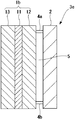
図1は、本発明における構造体の第1の実施の形態を示す断面図である。
Embodiments to which the sound absorbing material of the present invention is applied will be described below with reference to the drawings.
[First Embodiment]
FIG. 1 is a cross-sectional view showing a first embodiment of a structure according to the present invention.
同図において、本発明の吸音材1aは、シリコーンゴムから成る膜11と、膜11の背面側に積層される多孔質体層(以下「第1の多孔質体層」という。)12とを備えている。ここで、シリコーンゴムから成る膜11の背面側に、第1の多孔質体層12を積層するのは、膜11部分が付加質量、すなわち錘の役割として作用し、第1の多孔質体層12の部分がバネ、すなわち空気バネの役割として作用し、膜振動による吸音を行わせるためである。
In the figure, a
かかる吸音材1aは、剛壁2に対して、第1の多孔質体層12を剛壁2側に向けて、かつ剛壁2と平行に設置されることで、本発明の構造体3aが形成されることになる。
The
膜11は、難燃性を有し、かつ燃焼時に有害ガスを発生しない材料で形成されている。具体的には、後述するようにシリコーンゴムに硫酸バリウムを混入したもので形成されている。
The film |
次に、このような構成の膜11に要求される諸性能について説明する。
Next, various performances required for the
第1に、膜11としては単位体積当たりの燃焼発熱量が8MJ/m2以下のものを使用することが好ましい。膜11の単位体積当たりの燃焼発熱量が8MJ/m2を越えると、本実施例による製品の適用法規である建築基準法第2条第9号に規定される不燃グレードに適合できないからである。なお、膜11の燃焼発熱量は膜11の原料用樹脂に配合させる無機フィラーの種類や配合量などにより調節することができる。
First, it is preferable to use a
前述のシリコーンゴムから成る膜11によれば、幅100mm、長さ100mm、厚さ3〜50mmの試験片において、ISO5660で規定する燃焼発熱量試験において、単位体積当たりの燃焼発熱量を8MJ/m2以下にすることができる。
According to the above-described
第2に、膜11としては燃焼発熱速度が[200kW/m2] ・10sec以下のもの使用することが好ましい。膜11の燃焼発熱速度が[200kW/m2]・10secを越えると、建築基準法第2条第9号に規定の不燃グレードに適合しないからである。
Second, it is preferable to use a
前述のシリコーンゴムから成る膜11によれば、幅100mm、長さ100mm、厚さ3〜50mmの試験片において、ISO5660で規定する燃焼発熱速度試験において、燃焼発熱速度を[200kW/m2]・10sec以下にすることができる。
According to the above-described
次に、第1の多孔質体層12は、難燃性を有する材料で形成されている。具体的には、グラスウール、ロックウールの何れかまたはこれらの混合物から成るもので形成されている。
Next, the 1st
このような構成の膜11は、製品形態の自由度を向上させ、現場における施工を簡単にするため、接着やシリコーングラフト反応等により第1の多孔質体層12と一体化することが好ましい。
The
このような構成の吸音材1aを用いた構造体3aによれば、吸音材自身に建築基準法における難燃の規格に適合する難燃性が付与されているので、当該吸音材を難燃性が必要とされる場所に設置することができ、また、難燃剤としてハロゲン系難燃剤や鉛系化合物が使用されていないので、吸音材が燃焼しても燃焼時に有毒ガスを発生する虞がなく、さらに、膜11が第1の多孔質体層12と一体化されているので、現場における施工を簡単に行なうことができる。
According to the
ここで、前述の実施例では、膜11をシリコーンゴムのみで形成した場合について述べているが、膜11は、シリコーンゴムに2:1〜1:1の比で、Si、Ca、Sr、Baの何れか1種を含む化合物またはSi、Ca、Sr、Baの何れか1種を含む化合物の混合物から成る無機化合物を混入したもので形成してもよい。
Here, in the above-described embodiment, the case where the
このような構成の膜11においては、ネットワーク構造のシリコーンゴムの多孔室部分に嵩さ密度が高くかつ粒径の小さい硫酸バリウム等を混入することで、不燃性でかつ柔軟性がある上、所定の面密度を有する膜を形成することができる。
In the
図2は、本発明の実施例における膜の吸音率、面密度、膜厚、発熱量、発熱速度を比較例とともに示した説明図である。 FIG. 2 is an explanatory diagram showing the sound absorption coefficient, surface density, film thickness, heat generation amount, and heat generation rate of the film in the example of the present invention together with a comparative example.
ここで、本実施例の膜は、シリコーンゴムに2:1の比でシリカ、炭酸カルシウム、炭酸ストロンチウム、硫酸バリウムを混入したもの形成されており、比較例としてウレタンから成る膜が使用されている。 Here, the film of this example is formed by mixing silicone rubber with silica, calcium carbonate, strontium carbonate, and barium sulfate at a ratio of 2: 1, and a film made of urethane is used as a comparative example. .
なお、発熱量は建築基準法第2条第9号に規定する方法により、発熱速度はISO5660に規定する方法により測定した。
The calorific value was measured by the method specified in
同図より、本実施例における膜は、その膜厚を比較例の膜厚より略1/3程度薄くしても、比較例と同等の吸音率および面密度を得ることができる。また、建築基準法第2条第9号に規定する不燃グレードに適合させることができ、さらに、燃焼発熱速度を[200kW/m2]・10sec未満にすることができる。
From the figure, it is possible to obtain the sound absorption coefficient and the surface density equivalent to those of the comparative example, even if the film thickness of the present example is about 1/3 thinner than that of the comparative example. Moreover, it can adapt to the nonflammable grade prescribed | regulated to Building
図3は、第1の実施の形態における吸音材1aの吸音特性を示している。ここで、図中、点線L1は、多孔質体層(グラスウール)の厚さを100mmとした従来の吸音材の吸音特性、実線L2は、膜(シリコーンゴム膜)11の厚さを0.5mm、第1の多孔質体層(グラスウール)12の厚さを75mmとした第1の実施の形態における不燃性吸音材の吸音特性を示している。
FIG. 3 shows the sound absorption characteristics of the
同図より、従来の吸音材(L1)は、200Hz程度を超える高周波領域では吸音率が高いものの、200Hz程度以下の低周波領域では吸音率が低く、これに対して、第1の実施の形態における吸音材(L2)は、200Hz以上の高周波領域では吸音率が低いものの、200Hz以下の低周波領域では吸音率が高いことが分かる。従って、第1の実施の形態における吸音材を使用すれば、低周波領域に対応可能な吸音材を提供することができる。
[第2の実施の形態]
図4は、第1の実施の形態における吸音材1aを使用した膜状吸音構造の構造体の断面図を示している。なお、同図において、図1と共通する部分に同一の符号を付して詳細な説明を省略する。
From the figure, the conventional sound absorbing material (L1) has a high sound absorption coefficient in a high frequency region exceeding about 200 Hz, but has a low sound absorption coefficient in a low frequency region of about 200 Hz or less. It can be seen that the sound absorbing material (L2) has a low sound absorption rate in a high frequency region of 200 Hz or higher, but a high sound absorption rate in a low frequency region of 200 Hz or less. Therefore, if the sound absorbing material in the first embodiment is used, it is possible to provide a sound absorbing material that can cope with a low frequency region.
[Second Embodiment]
FIG. 4 shows a cross-sectional view of the structure of the film-like sound absorbing structure using the
図4において、本発明の構造体3bは、剛壁2と、剛壁2の音源側に、第1の多孔質体層12を剛壁2側に向けて、一対の支持部材4a、4bを介して剛壁2と平行に設置される膜状(厚さ:0.5mm程度)の吸音材1aと、吸音材1aと剛壁2により区画される背後空気層5とを備えている。
In FIG. 4, the
このような構成の膜状吸音構造の構造体3bにおいては、膜状の吸音材1aの質量に対して背後空気層5がバネとして作用し、単一共振系を形成し、音波の周波数がこの単一共振系の共振周波数と一致したとき膜状の吸音材1aが振動し内部摩擦により吸音されることになる。従って、第2の実施の形態における構造体3bによれば、前述と同様に、難燃性が必要とされる場所に設置することができ、また、難燃剤としてハロゲン系難燃剤や鉛系化合物が使用されていないので、吸音材が燃焼しても燃焼時に有毒ガスを発生する虞がなく、さらに、膜11が第1の多孔質体層12と一体化されているので、現場における施工を簡単に行なうことができる上、第1の実施の形態における構造体3aよりもさらに吸音率を向上させることができる。
[第3の実施の形態]
図5は、第1の実施の形態における吸音材1aを遮音壁に適用した構造体の断面図を示している。なお、同図において、図1と共通する部分に同一の符号を付して詳細な説明を省略する。
In the
[Third Embodiment]
FIG. 5 shows a cross-sectional view of a structure in which the
図5において、本発明の構造体3cは、例えば建物内部の床上に簡易間仕切りとして設けられた中空二重壁体6を備えている。
In FIG. 5, the structure 3c of this invention is equipped with the hollow
中空二重壁体6は、音源側に配設される第1の壁部材6aと、受音側に第1の壁部材6aから所定長離間した位置に第1の壁部材6aと平行に配設される第2の壁部材6bとを備えており、これらの第1、第2の壁部材6a、6b間に、前述の吸音材1aが第1の壁部材6a(若しくは第2の壁部材6b)と平行に配設されている。
The hollow
このような構成の構造体によれば、第1、第2の壁部材6a、6b間に吸音材自身に建築基準法における難燃の規格に適合する難燃性が付与された吸音材1aが配設されているので、前述と同様に、難燃性が必要とされる場所に設置することができ、また、難燃剤としてハロゲン系難燃剤や鉛系化合物が使用されていないので、吸音材が燃焼しても燃焼時に有毒ガスを発生する虞がなく、さらに、膜11が第1の多孔質体層12と一体化されているので、現場における施工を簡単に行なうことができる。
According to the structure having such a configuration, the
[第4の実施の形態]
図6は、本発明における他の構造体の第4の実施の形態を示
す断面図である。なお、同図において、図1と共通する部分には同一の符号を付して詳細な説明を省略する。
[Fourth Embodiment]
FIG. 6 is a cross-sectional view showing a fourth embodiment of another structure according to the present invention. In the figure, parts common to those in FIG. 1 are denoted by the same reference numerals and detailed description thereof is omitted.
図6において、本発明の他の吸音材1bは、シリコーンゴムから成る膜11と、膜11の背面側に積層される第1の多孔質体層12と、膜11の前面側に積層される多孔質体層(以下「第2の多孔質体層」という。)13とを備えている。
In FIG. 6, another
ここで、膜11の両面に、第1、第2の多孔質体層12、13を積層するのは、膜11部分が付加質量、すなわち錘の役割として作用し、第1、第2の多孔質体層12、13がバネ、すなわち空気バネの役割として作用し、膜振動による吸音を行わせるためである。
Here, the first and second porous body layers 12 and 13 are laminated on both surfaces of the
なお、第2の多孔質体層13は、前述の第1の多孔質体層12と同様の材料で形成されている。また、膜11は、第1、第2の多孔質体層12、13のうち少なくとも何れか一方と、前述と同様の手段により、一体化させることが好ましい。
In addition, the 2nd
このような構成の他の吸音材1bは、剛壁2に対して、第1の多孔質体層12を剛壁2側に向けて、かつ剛壁2と平行に設置されることで本発明の構造体3dが形成されることになる。
The other sound-absorbing
図7は、第4の実施の形態における吸音材の吸音特性を示している。ここで、図中、点線L1は、図3に示すものと同様に、多孔質体層(グラスウール)の厚さを100mmとした従来の吸音材の吸音特性、実線L3は、膜(シリコーンゴム膜)11の厚さを0.5mm、第1、第2の多孔質体層(グラスウール)12、13の厚さを75mmとした第4の実施の形態における吸音材の吸音特性を示している。 FIG. 7 shows the sound absorption characteristics of the sound absorbing material in the fourth embodiment. Here, in the figure, the dotted line L1 is the sound absorption characteristic of a conventional sound absorbing material in which the thickness of the porous body layer (glass wool) is 100 mm, and the solid line L3 is a film (silicone rubber film), as shown in FIG. ) The sound absorption characteristics of the sound absorbing material in the fourth embodiment in which the thickness of 11 is 0.5 mm and the thickness of the first and second porous body layers (glass wool) 12 and 13 is 75 mm.
同図より、従来の吸音材(L1)は、前述と同様に、200Hz程度を超える高周波領域では吸音率が高いものの、200Hz程度以下の低周波領域では吸音率が低く、これに対して、第4の実施の形態における吸音材(L3)は、200Hz程度以下の低周波領域のみならず、200Hz程度以上の高周波領域にわたって、優れた吸音特性を示していることが分かる。従って、第4の実施の形態における吸音材を使用すれば、広帯域の周波数領域に対応可能な吸音材を提供することができる。
[第5の実施の形態]
図8は、第4の実施の形態における吸音材1bを使用した膜状吸音構造の構造体の断面図を示している。なお、同図において、図1、図4および図6と共通する部分には同一の符号を付して詳細な説明を省略する。
As shown in the figure, the conventional sound absorbing material (L1) has a high sound absorption rate in a high frequency region exceeding about 200 Hz, but has a low sound absorption rate in a low frequency region of about 200 Hz or less. It can be seen that the sound absorbing material (L3) in the fourth embodiment exhibits excellent sound absorbing characteristics not only in a low frequency region of about 200 Hz or less but also in a high frequency region of about 200 Hz or more. Therefore, if the sound absorbing material in the fourth embodiment is used, it is possible to provide a sound absorbing material that can cope with a wide frequency range.
[Fifth Embodiment]
FIG. 8 shows a cross-sectional view of the structure of the film-like sound absorbing structure using the
図8において、本発明の構造体3eは、剛壁2と、剛壁2の音源側に、第1の多孔質体層12を剛壁2側に向けて、一対の支持部材4a、4bを介して剛壁2と平行に設置される膜状(厚さ:0.5mm程度)の吸音材1bと、吸音材1bと剛壁2により区画される背後空気層5とを備えている。
In FIG. 8, the structure 3e of the present invention includes a
このような構成の膜状吸音構造の構造体3eにおいては、前述と同様に、膜状の吸音材1bの質量に対して背後空気層5がバネとして作用し、単一共振系を形成し、音波の周波数がこの単一共振系の共振周波数と一致したとき膜状の吸音材1bが振動し内部摩擦により吸音されることになる。従って、第5の実施の形態における構造体3eによれば、前述と同様に、難燃性が必要とされる場所に設置することができ、また、難燃剤としてハロゲン系難燃剤や鉛系化合物が使用されていないので、吸音材が燃焼しても燃焼時に有毒ガスを発生する虞がなく、さらに、膜11が第1の多孔質体層12と一体化されているので、現場における施工を簡単に行なうことができる上、さらに、第4の実施の形態における構造体3bよりもさらに吸音率を向上させることができる。
[第6の実施の形態]
図9は、第4の実施の形態における吸音材1bを遮音壁に適用した構造体の断面図を示している。なお、同図において、図1、図5および図6と共通する部分に同一の符号を付して詳細な説明を省略する。
In the structure 3e of the film-like sound absorbing structure having such a configuration, the
[Sixth Embodiment]
FIG. 9 shows a cross-sectional view of a structure in which the
図9において、本発明の構造体3fは、前述と同様に、建物内部の床上に簡易間仕切りとして設けられた中空二重壁体6を備えている。
In FIG. 9, the
中空二重壁体6は、前述と同様に、音源側に配設される第1の壁部材6aと、受音側に第1の壁部材6aから所定長離間した位置に第1の壁部材6aと平行に配設される第2の壁部材6bとを備えており、これらの第1、第2の壁部材6a、6b間に、第4の実施の形態における吸音材1bが第1の壁部材6a(若しくは第2の壁部材6b)と平行に配設されている。
As described above, the hollow
このような構成の構造体によれば、第1、第2の壁部材6a、6b間に、吸音材自身に建築基準法における難燃の規格に適合する難燃性が付与された吸音材1bが配設されているので、前述と同様に、難燃性が必要とされる場所に設置することができ、また、難燃剤としてハロゲン系難燃剤や鉛系化合物が使用されていないので、吸音材が燃焼しても燃焼時に有毒ガスを発生する虞がなく、さらに、膜11が第1の多孔質体層12と一体化されているので、現場における施工を簡単に行なうことができる。
According to the structure having such a configuration, the
本発明は、特許請求の範囲内で、次のように、変更、修正を加えることができる。 The present invention can be changed and modified as follows within the scope of the claims.
第1に、前述の実施例においては、膜としてシリコーンゴムを使用した場合について説明しているが、シリコーンゴムに代えて、天然ゴム、イソプレンゴム、スチレンブタジエンゴム、ブタジエンゴム、ニトリルブタジエンゴム、ブチルゴム、エチレンプロピレンゴム、フッ素ゴム、クロロスルホン化ポリエチレンゴム、塩素化ポリエチレンゴム、エピクロロヒドリンゴム、多硫化ゴム、ポリオレフィンのうちから選択された何れかのゴムを使用してもよい。 First, in the above-described embodiment, the case where silicone rubber is used as the film is described. However, instead of silicone rubber, natural rubber, isoprene rubber, styrene butadiene rubber, butadiene rubber, nitrile butadiene rubber, butyl rubber are used. Any rubber selected from ethylene propylene rubber, fluorine rubber, chlorosulfonated polyethylene rubber, chlorinated polyethylene rubber, epichlorohydrin rubber, polysulfide rubber, and polyolefin may be used.
第2に、前述の実施例においては、膜11が接着やシリコーングラフト反応等の手段により第1、第2の多孔質体層12、13のうち、すくなくとも何れか一方と一体化させる場合について述べているが、膜11および/または第1、第2の多孔質体層12、13を加熱し、膜11および/または第1、第2の多孔質体層12、13が軟化する温度(例えば、80℃)になったときに、多少の圧力を付与することで両者を一体化させることができる。
Second, in the above-described embodiment, the case where the
第3に、前述の実施例(図5、図9)においては、第1、第2の壁部材2、3間に、第1、第4の実施の形態における吸音材1a、1bを配設した遮音壁について述べているが、第1、第2の壁部材2、3間に、第2の壁部材3の音源側に一対の支持部材5a、5bを介して第2の壁部材3と平行に第1、第4の実施の形態における吸音材1a、1bを配設してもよい。
Thirdly, in the above-described embodiment (FIGS. 5 and 9), the
第4に、前述の実施例においては、膜の燃焼発熱量および燃焼発熱速度について述べているが、吸音材自身の燃焼発熱量を8MJ/m2以下、燃焼発熱速度を[200kW/m2]・10sec以下としてもよい。 Fourthly, in the above-described embodiment, the combustion heat generation amount and the combustion heat generation rate of the film are described, but the combustion heat generation amount of the sound absorbing material itself is 8 MJ / m 2 or less, and the combustion heat generation rate is [200 kW / m 2 ]. -It is good also as 10 sec or less.
1a、1b・・・吸音材
11・・・シリコーンゴムから成る膜
12・・・多孔質体層(第1の多孔質体層)
13・・・多孔質体層(第2の多孔質体層)
2・・・剛壁
3a、3b、3c、3d、3e・・・構造体
4a、4b・・・支持部材
5・・・背後空気層
6・・・中空二重壁体
6a・・・第1の壁部材
6a・・・第2の壁部材
DESCRIPTION OF
13 ... porous body layer (second porous body layer)
2 ...
Claims (8)
前記吸音材は、音源側に向けて設置され、付加質量として作用するシリコーンゴムから成る膜と、前記膜の背面側に積層一体化されて前記剛壁側に向けて設置され、バネとして作用するグラスウール、ロックウールの何れかまたはこれらの混合物から成る多孔質体層とを備え、
前記膜は前記シリコーンゴムに2:1の比でシリカ、炭酸カルシウム、炭酸ストロンチウム、硫酸バリウムの何れか1種を混入して形成され、前記膜の燃焼発熱量は、8MJ/m 2 以下、燃焼発熱速度は[200kW/m 2 ]・10sec以下であることを特徴とする構造体。 And rigid wall, said rigid wall and disposed parallel to, and a sound absorbing material that by the membrane vibration,
The sound-absorbing material is installed toward the sound source side, and a film made of silicone rubber that acts as an additional mass, and is laminated and integrated on the back side of the film and installed toward the rigid wall side, and acts as a spring A porous body layer made of either glass wool, rock wool or a mixture thereof,
The film is formed by mixing any one of silica, calcium carbonate, strontium carbonate, and barium sulfate in a ratio of 2: 1 to the silicone rubber, and the heating value of the film is 8 MJ / m 2 or less. structure heat generation rate is characterized by der Rukoto following [200kW / m 2] · 10sec .
前記吸音材は、付加質量として作用するシリコーンゴムから成る膜と、前記膜の背面側に積層されて前記剛壁側に向けて設置され、バネとして作用するグラスウール、ロックウールの何れかまたはこれらの混合物から成る第1の多孔質体層と、前記膜の音源側に積層され、バネとして作用するグラスウール、ロックウールの何れかまたはこれらの混合物から成る第2の多孔質体層とを備え、
前記膜は前記第1、第2の多孔質体層のうち少なくとも何れか一方と一体化され、前記膜は前記シリコーンゴムに2:1の比でシリカ、炭酸カルシウム、炭酸ストロンチウム、硫酸バリウムの何れか1種を混入して形成され、前記膜の燃焼発熱量は、8MJ/m 2 以下、燃焼発熱速度は[200kW/m 2 ]・10sec以下であることを特徴とする構造体。 And rigid wall, said rigid wall and disposed parallel to, and a sound absorbing material that by the membrane vibration,
The sound absorbing material is a film made of silicone rubber acting as an additional mass, laminated on the back side of the film and installed toward the rigid wall, and is either glass wool or rock wool acting as a spring or these A first porous body layer made of a mixture, and a second porous body layer made of glass wool, rock wool, or a mixture thereof, laminated on the sound source side of the membrane and acting as a spring,
The membrane is integrated with at least one of the first and second porous layers, and the membrane is any one of silica, calcium carbonate, strontium carbonate, and barium sulfate in a ratio of 2: 1 to the silicone rubber. or it is formed by mixing one, combustion heating value of the film, 8 MJ / m 2 or less, combustion heat release rate is [200kW / m 2] · 10sec structure characterized by the following der Rukoto.
前記吸音材は、前記第1の壁部側に向けて設置され、付加質量として作用するシリコーンゴムから成る膜と、前記膜の背面側に積層一体化されて前記第2の壁部側に向けて設置され、バネとして作用するグラスウール、ロックウールの何れかまたはこれらの混合物から成る多孔質体層とを備え、
前記膜は前記シリコーンゴムに2:1の比でシリカ、炭酸カルシウム、炭酸ストロンチウム、硫酸バリウムの何れか1種を混入して形成され、前記膜の燃焼発熱量は、8MJ/m 2 以下、燃焼発熱速度は[200kW/m 2 ]・10sec以下であることを特徴とする構造体。 A hollow double wall body provided with a first wall member disposed on the sound source side and a second wall member disposed on the sound receiving side, and disposed between the first and second wall members. With sound absorbing material by membrane vibration ,
The sound absorbing material is installed toward the first wall portion side, and is laminated and integrated on the back side of the membrane made of silicone rubber that acts as an additional mass, and toward the second wall portion side. And a porous body layer made of glass wool, rock wool or a mixture thereof acting as a spring,
The film is formed by mixing any one of silica, calcium carbonate, strontium carbonate, and barium sulfate in a ratio of 2: 1 to the silicone rubber, and the heating value of the film is 8 MJ / m 2 or less. structure heat generation rate is characterized by der Rukoto following [200kW / m 2] · 10sec .
前記吸音材は、付加質量として作用するシリコーンゴムから成る膜と、前記膜の背面側に積層されて前記第1の壁部側に向けて配置され、バネとして作用するグラスウール、ロックウールの何れかまたはこれらの混合物から成る第1の多孔質体層と、前記膜の前面側に積層されて前記第2の壁部側に向けて配置され、バネとして作用するグラスウール、ロックウールの何れかまたはこれらの混合物から成る第2の多孔質体層とを備え、
前記膜は前記第1、第2の多孔質体層のうち少なくとも何れか一方と一体化され、前記膜は前記シリコーンゴムに2:1の比でシリカ、炭酸カルシウム、炭酸ストロンチウム、硫酸バリウムの何れか1種を混入して形成され、前記膜の燃焼発熱量は、8MJ/m 2 以下、燃焼発熱速度は[200kW/m 2 ]・10sec以下であることを特徴とする構造体。 A hollow double wall body provided with a first wall member disposed on the sound source side and a second wall member disposed on the sound receiving side, and disposed between the first and second wall members. With sound absorbing material by membrane vibration ,
The sound absorbing material is a film made of silicone rubber that acts as an additional mass, and is laminated on the back side of the film and arranged toward the first wall side, and is either glass wool or rock wool that acts as a spring. Or a first porous body layer made of a mixture of these, and glass wool or rock wool that is laminated on the front side of the membrane and arranged toward the second wall side and acts as a spring, or these A second porous body layer made of a mixture of
The membrane is integrated with at least one of the first and second porous layers, and the membrane is any one of silica, calcium carbonate, strontium carbonate, and barium sulfate in a ratio of 2: 1 to the silicone rubber. or it is formed by mixing one, combustion heating value of the film, 8 MJ / m 2 or less, combustion heat release rate is [200kW / m 2] · 10sec structure characterized by the following der Rukoto.
Priority Applications (1)
| Application Number | Priority Date | Filing Date | Title |
|---|---|---|---|
| JP2011237406A JP5432968B2 (en) | 2005-03-17 | 2011-10-28 | Structure |
Applications Claiming Priority (3)
| Application Number | Priority Date | Filing Date | Title |
|---|---|---|---|
| JP2005077593 | 2005-03-17 | ||
| JP2005077593 | 2005-03-17 | ||
| JP2011237406A JP5432968B2 (en) | 2005-03-17 | 2011-10-28 | Structure |
Related Parent Applications (1)
| Application Number | Title | Priority Date | Filing Date |
|---|---|---|---|
| JP2007508019A Division JP4891897B2 (en) | 2005-03-17 | 2005-12-09 | Structure |
Publications (2)
| Publication Number | Publication Date |
|---|---|
| JP2012073620A JP2012073620A (en) | 2012-04-12 |
| JP5432968B2 true JP5432968B2 (en) | 2014-03-05 |
Family
ID=36991421
Family Applications (2)
| Application Number | Title | Priority Date | Filing Date |
|---|---|---|---|
| JP2007508019A Active JP4891897B2 (en) | 2005-03-17 | 2005-12-09 | Structure |
| JP2011237406A Active JP5432968B2 (en) | 2005-03-17 | 2011-10-28 | Structure |
Family Applications Before (1)
| Application Number | Title | Priority Date | Filing Date |
|---|---|---|---|
| JP2007508019A Active JP4891897B2 (en) | 2005-03-17 | 2005-12-09 | Structure |
Country Status (6)
| Country | Link |
|---|---|
| US (1) | US20080164093A1 (en) |
| EP (1) | EP1859928A1 (en) |
| JP (2) | JP4891897B2 (en) |
| KR (1) | KR20070114288A (en) |
| TW (1) | TW200634726A (en) |
| WO (1) | WO2006098064A1 (en) |
Families Citing this family (15)
| Publication number | Priority date | Publication date | Assignee | Title |
|---|---|---|---|---|
| US20110100747A1 (en) * | 2006-05-24 | 2011-05-05 | Airbus Operations Gmbh | Sandwich element for the sound-absorbing inner cladding of means of transport, especially for the sound-absorbing inner cladding of aircraft |
| JP5326472B2 (en) * | 2007-10-11 | 2013-10-30 | ヤマハ株式会社 | Sound absorption structure |
| EP2232482B1 (en) * | 2007-12-21 | 2014-03-19 | 3M Innovative Properties Company | Sound barrier for audible acoustic frequency management |
| EP2223296B1 (en) * | 2007-12-21 | 2011-09-28 | 3m Innovative Properties Company | Viscoelastic phononic crystal |
| JP2009216898A (en) * | 2008-03-10 | 2009-09-24 | Swcc Showa Device Technology Co Ltd | Sound insulating device |
| JP4844935B2 (en) * | 2008-04-25 | 2011-12-28 | 東京ブラインド工業株式会社 | Sound absorption panel |
| JP5245641B2 (en) * | 2008-08-20 | 2013-07-24 | ヤマハ株式会社 | Sound absorbing structure |
| JP2010186144A (en) * | 2009-02-13 | 2010-08-26 | Swcc Showa Device Technology Co Ltd | Sound insulating device |
| JP2010286535A (en) * | 2009-06-09 | 2010-12-24 | Taisei Corp | Sound-absorbing material and sound absorbing structure using the same |
| WO2010151533A2 (en) | 2009-06-25 | 2010-12-29 | 3M Innovative Properties Company | Sound barrier for audible acoustic frequency management |
| AT509717B1 (en) * | 2010-12-23 | 2011-11-15 | Big Bau Und Immobilienges M B H | NOISE ELEMENT |
| JP5816007B2 (en) * | 2011-07-08 | 2015-11-17 | 大成建設株式会社 | Sound absorbing material |
| ITUB20152261A1 (en) * | 2015-07-17 | 2017-01-17 | Mecaer Aviation Group S P A | MULTILAYER PANEL FOR SOUNDPROOFING OF AIRCRAFT INTERIORS |
| JP6646267B1 (en) * | 2019-03-22 | 2020-02-14 | Jnc株式会社 | Laminated sound absorbing material |
| CN116731609B (en) * | 2023-07-25 | 2024-08-13 | 尚德环保科技有限公司 | Silicone rubber sound absorption coating and preparation method thereof |
Family Cites Families (52)
| Publication number | Priority date | Publication date | Assignee | Title |
|---|---|---|---|---|
| US1867549A (en) * | 1929-07-19 | 1932-07-19 | Acoustical Correction Corp | Sound absorbent material |
| US2169370A (en) * | 1936-12-19 | 1939-08-15 | Johns Manville | Sound-absorbing article |
| US2573482A (en) * | 1945-04-25 | 1951-10-30 | Thomas L Fawick | Sound-deadening unit |
| US2745173A (en) * | 1951-07-14 | 1956-05-15 | Gen Electric | Method of thermal insulation |
| US2851730A (en) * | 1952-10-17 | 1958-09-16 | Holzwerke H Wilhelmi O H G Fa | Production of multi-layer boards |
| US2959242A (en) * | 1954-12-21 | 1960-11-08 | Bayer Ag | Sound-absorbing system |
| US3621934A (en) * | 1970-05-18 | 1971-11-23 | Goodrich Co B F | Acoustic wall coverings |
| JPS532892Y2 (en) * | 1974-02-04 | 1978-01-25 | ||
| US4488619A (en) * | 1984-04-11 | 1984-12-18 | Neill Justin T O | Foam-barrier-foam-facing acoustical composite |
| JPS6475752A (en) * | 1987-09-18 | 1989-03-22 | Ozeki Chem Ind | Sound-insulating laminated panel material |
| NL8702324A (en) * | 1987-09-29 | 1989-04-17 | Ir George Gustaaf Veldhoen | METHOD FOR MANUFACTURING FLAT PANELS CONTAINING A CORE OF SOFT FILLING MATERIAL AND A CORE FILM-COVERING THAT CORE |
| DE8715142U1 (en) * | 1987-11-13 | 1988-06-01 | Dr. Alois Stankiewicz GmbH, 3101 Adelheidsdorf | Sound insulation part with absorption properties for partition wall |
| US5068001A (en) * | 1987-12-16 | 1991-11-26 | Reinhold Haussling | Method of making a sound absorbing laminate |
| US4940112A (en) * | 1989-06-20 | 1990-07-10 | Neill Justin T O | High performance flame and smoke foam-barrier-foam-facing acoustical composite |
| JPH0325509U (en) * | 1989-07-21 | 1991-03-15 | ||
| US5125475A (en) * | 1990-08-09 | 1992-06-30 | Les Materiaux Cascades Inc. | Acoustic construction panel |
| US5536556A (en) * | 1991-02-20 | 1996-07-16 | Indian Head Industries, Inc. | Insulating laminate |
| JPH0626127A (en) * | 1992-07-03 | 1994-02-01 | Daiken Trade & Ind Co Ltd | Board for architecture |
| US5824973A (en) * | 1992-09-29 | 1998-10-20 | Johns Manville International, Inc. | Method of making sound absorbing laminates and laminates having maximized sound absorbing characteristics |
| US5459291A (en) * | 1992-09-29 | 1995-10-17 | Schuller International, Inc. | Sound absorption laminate |
| US5364681A (en) * | 1993-02-05 | 1994-11-15 | Gencorp Inc. | Acoustic lamina wall covering |
| DE69610787T2 (en) * | 1995-02-08 | 2001-05-10 | Kabushiki Kaisha Kobe Seiko Sho (Kobe Steel, Ltd.) | Heat laminatable vibration damping resin for structural elements, vibration damping element and manufacturing process therefor |
| JP2869702B2 (en) * | 1995-03-29 | 1999-03-10 | ニチアス株式会社 | Restrained damping material |
| DE29506265U1 (en) * | 1995-04-11 | 1996-08-14 | M. Faist GmbH & Co KG, 86381 Krumbach | Magnetizable flat damping element and adhesive especially for use with anti-drumming mats |
| JP3712012B2 (en) * | 1995-06-02 | 2005-11-02 | 信越化学工業株式会社 | Silicone rubber tube molding method and thin film silicone rubber sheet |
| US5665447A (en) * | 1995-10-18 | 1997-09-09 | Owens-Corning Fiberglas Technology, Inc. | Sound screen insulation with asphalt septum |
| JP3025509U (en) * | 1995-12-06 | 1996-06-21 | 九州アコン株式会社 | Sound absorbing wall structure |
| JPH1046701A (en) * | 1996-08-06 | 1998-02-17 | Nippon Shiyaken Kk | Soundproof material and execution work method of soundproof material |
| WO1998018656A1 (en) * | 1996-10-29 | 1998-05-07 | Rieter Automotive (International) Ag | Ultralight, multifunctional, sound-insulating material assembly |
| US5965851A (en) * | 1997-01-28 | 1999-10-12 | Owens Corning Fiberglas Technology, Inc. | Acoustically insulated apparatus |
| US6177180B1 (en) * | 1997-06-02 | 2001-01-23 | Armstrong World Industries, Inc. | Composite construction board with load bearing properties |
| US5975237A (en) * | 1997-07-30 | 1999-11-02 | The Boeing Company | Reinforcing structure for engine nacelle acoustic panel |
| US5874136A (en) * | 1997-10-17 | 1999-02-23 | Ut Automotive Dearborn, Inc. | Vehicle trim panel including felt and mat layers |
| US5892187A (en) * | 1997-12-17 | 1999-04-06 | United Technologies Corporation | Tunable recyclable headliner |
| CH692731A5 (en) * | 1998-01-09 | 2002-10-15 | Rieter Automotive Int Ag | Ultra-light, sound and shock absorbing kit. |
| US6613424B1 (en) * | 1999-10-01 | 2003-09-02 | Awi Licensing Company | Composite structure with foamed cementitious layer |
| US6345688B1 (en) * | 1999-11-23 | 2002-02-12 | Johnson Controls Technology Company | Method and apparatus for absorbing sound |
| JP2001260290A (en) * | 2000-03-21 | 2001-09-25 | Hagihara Industries Inc | Soundproofing sheet made of polyolefin |
| JP2001343741A (en) * | 2000-03-28 | 2001-12-14 | Fuji Photo Film Co Ltd | Original plate of planographic printing plate requiring no dampening water |
| JP2002060624A (en) * | 2000-08-21 | 2002-02-26 | Dow Corning Toray Silicone Co Ltd | Silicone rubber composition |
| JP2002067826A (en) * | 2000-08-25 | 2002-03-08 | Nissan Motor Co Ltd | Vehicular noise absorbing and insulating structure |
| US20020134615A1 (en) * | 2001-02-21 | 2002-09-26 | Herreman Kevin Michael | Noise reduction system for kitchen |
| EP1428656A1 (en) * | 2002-12-09 | 2004-06-16 | Rieter Technologies A.G. | Ultralight trim composite |
| US7320739B2 (en) * | 2003-01-02 | 2008-01-22 | 3M Innovative Properties Company | Sound absorptive multilayer composite |
| FR2850410B1 (en) * | 2003-01-24 | 2006-02-03 | Hutchinson | ACOUSTIC INSULATION PANEL |
| JP2004262068A (en) * | 2003-02-28 | 2004-09-24 | Sekisui Chem Co Ltd | Vibration-damping material |
| US20060191743A1 (en) * | 2003-04-07 | 2006-08-31 | Pike Clinton W Sr | Sound absorbing wall systems and methods of producing same |
| US7011181B2 (en) * | 2003-07-08 | 2006-03-14 | Lear Corporation | Sound insulation system |
| US7318499B2 (en) * | 2004-02-20 | 2008-01-15 | Honeywell International, Inc. | Noise suppression structure and method of making the same |
| US7318498B2 (en) * | 2004-04-06 | 2008-01-15 | Azdel, Inc. | Decorative interior sound absorbing panel |
| US20060289231A1 (en) * | 2005-06-28 | 2006-12-28 | Priebe Joseph A | Acoustic absorber/barrier composite |
| JP4361036B2 (en) * | 2005-07-13 | 2009-11-11 | 豊和繊維工業株式会社 | Sound insulation for vehicles |
-
2005
- 2005-12-09 JP JP2007508019A patent/JP4891897B2/en active Active
- 2005-12-09 KR KR1020077021276A patent/KR20070114288A/en not_active Application Discontinuation
- 2005-12-09 EP EP05814438A patent/EP1859928A1/en not_active Withdrawn
- 2005-12-09 WO PCT/JP2005/022670 patent/WO2006098064A1/en not_active Application Discontinuation
- 2005-12-09 US US11/885,162 patent/US20080164093A1/en not_active Abandoned
-
2006
- 2006-01-12 TW TW095101235A patent/TW200634726A/en unknown
-
2011
- 2011-10-28 JP JP2011237406A patent/JP5432968B2/en active Active
Also Published As
| Publication number | Publication date |
|---|---|
| JP2012073620A (en) | 2012-04-12 |
| TW200634726A (en) | 2006-10-01 |
| JPWO2006098064A1 (en) | 2008-08-21 |
| JP4891897B2 (en) | 2012-03-07 |
| WO2006098064A1 (en) | 2006-09-21 |
| US20080164093A1 (en) | 2008-07-10 |
| KR20070114288A (en) | 2007-11-30 |
| EP1859928A1 (en) | 2007-11-28 |
Similar Documents
| Publication | Publication Date | Title |
|---|---|---|
| JP5432968B2 (en) | Structure | |
| JP2007133246A (en) | Sound absorbing structure | |
| JP2009029962A (en) | Heat storage resin coating and board having heat storage property using the same | |
| JP2007047567A (en) | Acoustic material and structure using same | |
| KR20040063015A (en) | Acoustic absorption panel | |
| JP2007156309A (en) | Sound absorbing material | |
| CN214062196U (en) | Heat-preservation fireproof sound-insulation wallboard | |
| JP3718639B2 (en) | Seat waterproof structure with fire resistance | |
| JP4927362B2 (en) | Non-combustible sound absorbing material and structure using the same | |
| JPH10219866A (en) | Heat insulating panel and manufacture therefor | |
| JP2010286535A (en) | Sound-absorbing material and sound absorbing structure using the same | |
| JP2008034477A (en) | Soundproofing system for electric apparatus | |
| JP2007003827A (en) | Acoustic material and structure using same | |
| JP2007071962A (en) | Waterproof acoustic material and structure using the same | |
| JP2007071962A5 (en) | ||
| JP5816007B2 (en) | Sound absorbing material | |
| JP2007093738A (en) | Sound absorbing pipe | |
| KR20080018030A (en) | Floor impact noise isolator/shock-absorber for construction | |
| KR200296022Y1 (en) | A Functional Fireproof Hybrid Panel | |
| JP2007223496A (en) | Sound absorbing body, and moving body using the same | |
| JP2007326482A (en) | Sound absorbing body and movement body using this | |
| JP2008076869A (en) | Waterproof sound absorber | |
| KR101458116B1 (en) | Flexible soundproof panel | |
| JP2007218568A (en) | Exhaust device | |
| JP2008038498A (en) | Sound absorbing structure |
Legal Events
| Date | Code | Title | Description |
|---|---|---|---|
| A131 | Notification of reasons for refusal |
Free format text: JAPANESE INTERMEDIATE CODE: A131 Effective date: 20130416 |
|
| A521 | Request for written amendment filed |
Free format text: JAPANESE INTERMEDIATE CODE: A523 Effective date: 20130614 |
|
| TRDD | Decision of grant or rejection written | ||
| A01 | Written decision to grant a patent or to grant a registration (utility model) |
Free format text: JAPANESE INTERMEDIATE CODE: A01 Effective date: 20131112 |
|
| A61 | First payment of annual fees (during grant procedure) |
Free format text: JAPANESE INTERMEDIATE CODE: A61 Effective date: 20131206 |
|
| R150 | Certificate of patent or registration of utility model |
Free format text: JAPANESE INTERMEDIATE CODE: R150 Ref document number: 5432968 Country of ref document: JP Free format text: JAPANESE INTERMEDIATE CODE: R150 |
|
| S111 | Request for change of ownership or part of ownership |
Free format text: JAPANESE INTERMEDIATE CODE: R313111 |
|
| R350 | Written notification of registration of transfer |
Free format text: JAPANESE INTERMEDIATE CODE: R350 |
|
| S111 | Request for change of ownership or part of ownership |
Free format text: JAPANESE INTERMEDIATE CODE: R313111 |
|
| R371 | Transfer withdrawn |
Free format text: JAPANESE INTERMEDIATE CODE: R371 |
|
| S111 | Request for change of ownership or part of ownership |
Free format text: JAPANESE INTERMEDIATE CODE: R313111 |
|
| R350 | Written notification of registration of transfer |
Free format text: JAPANESE INTERMEDIATE CODE: R350 |