JP5432886B2 - Power control device - Google Patents
Power control device Download PDFInfo
- Publication number
- JP5432886B2 JP5432886B2 JP2010501539A JP2010501539A JP5432886B2 JP 5432886 B2 JP5432886 B2 JP 5432886B2 JP 2010501539 A JP2010501539 A JP 2010501539A JP 2010501539 A JP2010501539 A JP 2010501539A JP 5432886 B2 JP5432886 B2 JP 5432886B2
- Authority
- JP
- Japan
- Prior art keywords
- controller
- power control
- power
- speed
- control
- Prior art date
- Legal status (The legal status is an assumption and is not a legal conclusion. Google has not performed a legal analysis and makes no representation as to the accuracy of the status listed.)
- Active
Links
- 238000005259 measurement Methods 0.000 claims description 23
- 230000004044 response Effects 0.000 claims description 16
- 238000012546 transfer Methods 0.000 claims description 15
- 238000004891 communication Methods 0.000 claims description 12
- 238000012544 monitoring process Methods 0.000 claims description 12
- 238000003745 diagnosis Methods 0.000 claims description 8
- 230000001133 acceleration Effects 0.000 description 12
- 238000000034 method Methods 0.000 description 8
- 238000010248 power generation Methods 0.000 description 5
- 230000000903 blocking effect Effects 0.000 description 3
- 238000010586 diagram Methods 0.000 description 3
- 230000003213 activating effect Effects 0.000 description 2
- 230000009471 action Effects 0.000 description 1
- 239000003990 capacitor Substances 0.000 description 1
- 230000008859 change Effects 0.000 description 1
- 238000004590 computer program Methods 0.000 description 1
- 238000004146 energy storage Methods 0.000 description 1
- 238000005516 engineering process Methods 0.000 description 1
- 230000006872 improvement Effects 0.000 description 1
- 230000005764 inhibitory process Effects 0.000 description 1
- 230000005415 magnetization Effects 0.000 description 1
- 238000012545 processing Methods 0.000 description 1
- 230000007704 transition Effects 0.000 description 1
Images


Classifications
-
- B—PERFORMING OPERATIONS; TRANSPORTING
- B66—HOISTING; LIFTING; HAULING
- B66B—ELEVATORS; ESCALATORS OR MOVING WALKWAYS
- B66B5/00—Applications of checking, fault-correcting, or safety devices in elevators
- B66B5/02—Applications of checking, fault-correcting, or safety devices in elevators responsive to abnormal operating conditions
-
- B—PERFORMING OPERATIONS; TRANSPORTING
- B66—HOISTING; LIFTING; HAULING
- B66B—ELEVATORS; ESCALATORS OR MOVING WALKWAYS
- B66B1/00—Control systems of elevators in general
- B66B1/24—Control systems with regulation, i.e. with retroactive action, for influencing travelling speed, acceleration, or deceleration
- B66B1/28—Control systems with regulation, i.e. with retroactive action, for influencing travelling speed, acceleration, or deceleration electrical
- B66B1/30—Control systems with regulation, i.e. with retroactive action, for influencing travelling speed, acceleration, or deceleration electrical effective on driving gear, e.g. acting on power electronics, on inverter or rectifier controlled motor
- B66B1/308—Control systems with regulation, i.e. with retroactive action, for influencing travelling speed, acceleration, or deceleration electrical effective on driving gear, e.g. acting on power electronics, on inverter or rectifier controlled motor with AC powered elevator drive
-
- B—PERFORMING OPERATIONS; TRANSPORTING
- B66—HOISTING; LIFTING; HAULING
- B66B—ELEVATORS; ESCALATORS OR MOVING WALKWAYS
- B66B1/00—Control systems of elevators in general
- B66B1/34—Details, e.g. call counting devices, data transmission from car to control system, devices giving information to the control system
- B66B1/3415—Control system configuration and the data transmission or communication within the control system
- B66B1/3423—Control system configuration, i.e. lay-out
- B66B1/343—Fault-tolerant or redundant control system configuration
Landscapes
- Engineering & Computer Science (AREA)
- Automation & Control Theory (AREA)
- Computer Networks & Wireless Communication (AREA)
- Elevator Control (AREA)
Description
本発明は、請求項1の前段に記載のフェイルセーフ電力制御装置に関するものである。 The present invention relates to a fail-safe power control apparatus according to the first stage of claim 1.
エレベータシステムなどの輸送システムには従来から、輸送システムを制御する別個の制御システムと輸送システムの安全を確保する別個の安全システムとが設けられている。 Conventionally, a transportation system such as an elevator system is provided with a separate control system for controlling the transportation system and a separate safety system for ensuring the safety of the transportation system.
エレベータシステムの制御システムは、少なくとも1つのエレベータモータ、エレベータコントローラ、エレベータモータに給電する電力制御装置を含んでいる。エレベータコントローラはエレベータ群制御機能と、かご呼びおよび乗り場呼びを処理する機能とを含んでいる。 The control system of the elevator system includes at least one elevator motor, an elevator controller, and a power control device that supplies power to the elevator motor. The elevator controller includes an elevator group control function and a function for processing car calls and landing calls.
エレベータシステムの安全システムは安全回路を含み、これは障害状態で開く1つ以上の安全接触器の直列回路と、駆動機械ブレーキもしくは乗りかごブレーキなどの安全回路が開くと作動する安全装置とを有している。さらに、安全システムは、なかでも、速度超過の場合にエレベータかごの安全装置を作動させる超過速度ガバナと、エレベータシャフトの両端部にある終端緩衝器とを含んでもよい。 The safety system of an elevator system includes a safety circuit, which has a series circuit of one or more safety contactors that open in a fault condition and a safety device that operates when a safety circuit such as a drive machine brake or car brake is opened. doing. In addition, the safety system may include, among other things, an overspeed governor that activates the elevator car safety device in the event of overspeed, and end bumpers at both ends of the elevator shaft.
近年、輸送システムに関する安全規則が変わってきて、技術的規則上の観点では、さまざまな機械式安全装置を同様の電気式安全装置に置き換えることが可能になっている。 In recent years, safety rules regarding transportation systems have changed, and in terms of technical rules, various mechanical safety devices can be replaced with similar electrical safety devices.
米国特許第6,170,614号明細書は電子式超過速度ガバナを開示し、これは、エレベータシステムにおいて機械式の遠心力作動超過速度ガバナの代わりに使用することができる。電子式超過速度ガバナはエレベータかごの速度もしくは位置を測定し、そのエレベータかごの速度超過が発生中と判定すると、エレベータかごの安全装置などの停止装置を作動させてエレベータかごを停止させる。 U.S. Pat. No. 6,170,614 discloses an electronic overspeed governor that can be used in an elevator system in place of a mechanical centrifugally actuated overspeed governor. The electronic overspeed governor measures the speed or position of the elevator car, and when it is determined that the elevator car is overspeeding, it activates a stop device such as an elevator car safety device to stop the elevator car.
欧州特許第1,159,218号明細書は、エレベータシステム用に電子的に実現された安全回路を開示している。直列接続の安全接触器を有する従来のエレベータシステム安全回路は、安全接触器もしくは同等のセンサの状態を測定し、これを別のコントローラに直列転送で送信する装置を用いるように改良されている。安全回路のこのような改良は、電気安全機器に関する新しいエレベータシステム安全基準において、いわゆるPESSRAL基準で承認されている。 EP 1,159,218 discloses an electronically implemented safety circuit for an elevator system. Conventional elevator system safety circuits with safety contacts in series have been modified to use a device that measures the status of a safety contactor or equivalent sensor and transmits it in series transfer to another controller. Such an improvement of the safety circuit has been approved under the so-called PESSRAL standard in the new elevator system safety standard for electrical safety equipment.
個々の機械式安全装置もしくはリレーなどの機械スイッチを用いて実現される個々の安全装置を同等の電子式安全装置に代えることは、実質的に安全装置の数を少なくすることにはならない。安全装置の基本的機能はいまだに、輸送機器の速度もしくは位置などの特定の輸送システムパラメータを測定することと、測定したパラメータから輸送機器に障害発生中の可能性があるかを推測することに基づいている。例えば、輸送機器のモータを制御するインバータなどの電力制御装置に危険な障害が生じても、この障害は遅れて検出されるにすぎない。例えば、輸送機器の速度が最高許容速度の限界値を越える危険な水準まで加速されたら、超過速度ガバナによって検出されるにすぎない。 Replacing individual safety devices implemented using mechanical switches such as individual mechanical safety devices or relays with equivalent electronic safety devices does not substantially reduce the number of safety devices. The basic function of the safety device is still based on measuring certain transport system parameters such as the speed or position of the transport equipment and inferring from the measured parameters whether the transport equipment may be faulty. ing. For example, even if a dangerous failure occurs in a power control device such as an inverter that controls a motor of a transportation device, this failure is only detected with a delay. For example, if the speed of the transport equipment is accelerated to a dangerous level that exceeds the maximum allowable speed limit, it is only detected by an overspeed governor.
米国特許出願公開US 2003/0150690 A1号明細書は、輸送システムの速度モニタ用と同システムの停止用の2つのチャンネルを設けたフェイルセーフ制御装置を開示している。 US 2003/0150690 A1 discloses a fail-safe control device having two channels for speed monitoring of a transportation system and for stopping the system.
米国特許出願公開US 2006/0060427 A1号明細書は、輸送システムの速度モニタ用と同システムの停止用の2つのコントローラを設けたフェイルセーフ制御装置を開示している。 US 2006/0060427 A1 discloses a fail-safe control device with two controllers for speed monitoring of the transport system and for stopping the system.
本発明は、輸送システムに発生し得る障害状態を、従来技術の輸送システムの安全システムを用いた場合に起こり得るより実質的に早期に検出できるフェイルセーフ電力制御装置を開示することを目的とする。同時に、本発明は、輸送システムの安全システムを従来技術の安全システムよりもかなり簡易に作ることができる装置を開示することを目的とする。本発明によるフェイルセーフ電力制御装置を有する安全システムは、従来技術の安全システムより少数の個別の安全装置を有している。 It is an object of the present invention to disclose a fail-safe power control apparatus capable of detecting a fault condition that may occur in a transportation system substantially earlier than can occur when a safety system of a conventional transportation system is used. . At the same time, it is an object of the present invention to disclose an apparatus that can make the safety system of a transportation system much simpler than prior art safety systems. The safety system with the fail-safe power control device according to the present invention has fewer individual safety devices than prior art safety systems.
本発明のフェイルセーフ電力制御装置は、請求項1の特徴段に記載する事項を特徴とする。本発明の他の実施例は、その他の請求項に記載する事項を特徴とする。発明の実施例は本願の明細書部分にも提示されている。本願に開示した発明の内容は、下記の請求項にて定義した以外の方法により定義することもできる。本発明の内容はまた、とくに明示的もしくは暗示的サブタスクに照らして、または達成される利点もしくは複数の利点のいくつかの組合せに関して本発明を考慮すれば、いくつかの別個の発明を含むこともある。その場合、下記の請求項に含まれる属性の一部は、別の発明概念の観点から不要なこともある。 The fail-safe power control apparatus of the present invention is characterized by the matters described in the characteristic stage of claim 1. Other embodiments of the invention are characterized by what is set forth in the other claims. Embodiments of the invention are also presented in the specification part of the present application. The content of the invention disclosed in the present application can also be defined by methods other than those defined in the following claims. The subject matter of the present invention may also include several separate inventions, particularly in light of explicit or implicit subtasks, or in view of the present invention with respect to the advantages or combinations of advantages achieved. is there. In that case, some of the attributes included in the claims below may be unnecessary from the viewpoint of another inventive concept.
本発明は、輸送システム用のフェイルセーフ電力制御装置に関する。この意味でのフェイルセーフとは、どのような状況で障害が発生しても、電力制御装置により制御される輸送システムの利用者に装置の障害が危険を及ぼさずに安全であるよう設計された装置を言う。 The present invention relates to a fail-safe power control apparatus for a transportation system. Fail-safe in this sense is designed so that the failure of the equipment does not pose a danger to the user of the transportation system controlled by the power control device, regardless of the situation in which the failure occurs. Say device.
本発明に関わる輸送システムは、例えばエレベータシステム、エスカレータシステム、動く歩道システム、もしくはクレーンシステムであってよい。用語「輸送システム」とはここでは、エレベータシステムなどの輸送を目的としたシステム全体を言うが、一方、用語「輸送機器」とは、エレベータかごなど、実際の輸送に用いられるシステム構成機器を言う。 The transportation system according to the present invention may be, for example, an elevator system, an escalator system, a moving sidewalk system, or a crane system. The term “transport system” here refers to the entire system intended for transport, such as an elevator system, whereas the term “transport equipment” refers to system components used in actual transport, such as an elevator car. .
エネルギー源と輸送システムのモータとの間で給電を行なう本発明の電力制御装置は電源回路を有し、これは制御可能切替スイッチを有する少なくとも1つの電子的電力コンバータを含む。電力制御装置は、互いに通信するよう構成された少なくとも第1のコントローラと第2のコントローラを有し、これらのコントローラは全体で少なくとも1つのコンバータ制御機能を構成している。電力制御装置は少なくとも1つの制動装置の制御手段を有している。少なくとも第1のコントローラおよび第2のコントローラは、輸送機器の動きをモニタする輸送機器動き信号の入力と、少なくとも1つの制動装置に関する制御信号の出力とを有している。「輸送機器動き信号」とは、輸送機器の加速度、速度もしくは位置などの輸送機器の動き状態を示す信号を言う。このような信号は、例えば輸送機器の動きを測定するエンコーダもしくは加速度センサの測定信号でよい。同様に、「輸送機器の動きのモニタ」とは、輸送機器の加速度、速度もしくは位置などの動き状態をモニタすることを言う。「輸送機器の動き基準の判定」とは、輸送機器の加速度、速度もしくは位置などの動き状態に関する基準値/基準値の組を判定することを言う。 The power controller of the present invention, which supplies power between the energy source and the motor of the transportation system, has a power circuit, which includes at least one electronic power converter with a controllable changeover switch. The power control apparatus has at least a first controller and a second controller configured to communicate with each other, and these controllers together constitute at least one converter control function. The power control device has at least one braking device control means. At least the first controller and the second controller have a transport equipment motion signal input for monitoring transport equipment motion and a control signal output for at least one braking device. “Transport equipment motion signal” refers to a signal indicating the motion status of the transport equipment such as acceleration, speed or position of the transport equipment. Such a signal may be, for example, a measurement signal of an encoder or an acceleration sensor that measures the movement of the transportation device. Similarly, “monitoring the movement of the transportation device” means monitoring the movement state of the transportation device such as acceleration, speed, or position. “Determination of transport equipment movement reference” refers to judging a reference value / reference value pair related to a motion state such as acceleration, speed or position of a transport equipment.
本発明の実施例では、少なくとも第1のコントローラはインバータ制御手段を有し、少なくとも第2のコントローラは輸送機器の速度調節手段を有している。この場合、第1および第2のコントローラは輸送機器速度および/または位置を示す測定信号の入力、ならびに輸送機器の速度および/または位置をモニタする入力を有している。 In an embodiment of the present invention, at least the first controller has inverter control means, and at least the second controller has speed adjusting means for the transportation equipment. In this case, the first and second controllers have inputs for measurement signals indicative of the transport equipment speed and / or position, and inputs for monitoring the speed and / or position of the transport equipment.
本発明による電力制御装置において、第1および第2のコントローラは安全診断機能を含んでいる。「安全診断」とは、特定の安全手順に従って設計されたコンピュータプログラムおよび/または制御電子回路など、特定の安全手順に従って設計されたモニタリングもしくは制御を言う。 In the power control apparatus according to the present invention, the first and second controllers include a safety diagnosis function. “Safety diagnosis” refers to monitoring or control designed according to a specific safety procedure, such as a computer program and / or control electronics designed according to a specific safety procedure.
本発明の実施例では、上記の安全診断の障害状態を輸送機器の動きのモニタリングに基づいて判定する。 In the embodiment of the present invention, the failure state of the safety diagnosis is determined based on the monitoring of the movement of the transportation equipment.
本発明の実施例では、上記の安全診断の障害状態を第1コントローラと第2コントローラの間の通信に基づいて判定する。 In the embodiment of the present invention, the failure state of the safety diagnosis is determined based on the communication between the first controller and the second controller.
本発明による電力制御装置において、少なくとも第1および第2のコントローラは第1および第2の制動装置に関する制御信号の出力を有している。この場合、第1の制動装置は、輸送機器のモータの軸もしくは駆動綱車に機械的に係合する機械ブレーキでよい。第2の制動装置もやはり、上述のモータに係合する機械ブレーキ、または例えばエレベータかごとエレベータかごのガイドレールとの間で機械的に係合するレールブレーキもしくは超過速度ガバナ・ウエッジブレーキでよい。 In the power control apparatus according to the present invention, at least the first and second controllers have outputs of control signals related to the first and second braking devices. In this case, the first braking device may be a mechanical brake that mechanically engages the motor shaft or drive sheave of the transport equipment. The second braking device may also be a mechanical brake that engages the motor described above, or a rail brake or an overspeed governor / wedge brake that mechanically engages between the elevator car and the guide rails of the elevator car, for example.
本発明による電力制御装置において、第1のコントローラと第2のコントローラの間には通信バスが配設されている。第2のコントローラは第1のコントローラにメッセージを所定の時間間隔で送信するよう構成され、第1のコントローラは、このメッセージを受信すると第2のコントローラへ応答メッセージを所定の時間内に送信するよう構成されている。両コントローラは、メッセージもしくは応答メッセージの間の時間間隔で所定の限界値からの偏りを検出すると、それぞれが独立して輸送システムを停止させる動作を行なうよう構成されている。 In the power control apparatus according to the present invention, a communication bus is disposed between the first controller and the second controller. The second controller is configured to transmit a message to the first controller at a predetermined time interval, and when the first controller receives the message, the first controller transmits a response message to the second controller within the predetermined time. It is configured. When both controllers detect a deviation from a predetermined limit value in the time interval between the message or the response message, each controller is configured to perform an operation of stopping the transportation system independently.
本発明による電力制御装置において、メッセージおよび応答メッセージはいずれも少なくとも次のようなデータ項目、すなわち、メッセージもしくは応答メッセージを送信するコントローラにより読み取られた速度および/または位置の測定データ、メッセージもしくは応答メッセージを送信するコントローラにより検出された障害に関する通知、および少なくとも1つの制動装置に対する制御コマンドを含む。両コントローラは、制動装置に対する制御コマンド間の偏り、または各コントローラの速度および/もしくは位置の測定データの間の偏りを検出すると、または検出された誤りに関するメッセージを受信すると、それぞれが独自に輸送システムを停止させる動作を行なうよう構成されている。 In the power control apparatus according to the present invention, each of the message and the response message includes at least the following data items, that is, speed and / or position measurement data, message or response message read by the controller that transmits the message or response message. A notification about the fault detected by the controller that transmits and a control command for at least one braking device. When both controllers detect a deviation between control commands to the braking device, or a deviation between each controller's speed and / or position measurement data, or receive a message about the detected error, each controller independently It is comprised so that the operation | movement which stops may be performed.
本発明による電力制御装置は電源回路の遮断機能を有し、この場合、少なくとも第1および第2のコントローラは電源回路を遮断する制御信号の出力を有している。 The power control apparatus according to the present invention has a power supply circuit cutoff function. In this case, at least the first and second controllers have outputs of control signals for shutting down the power supply circuit.
本発明による電力制御装置は、コンバータの切替えスイッチを制御する制御手段を有し、上記制御手段は、少なくとも正の切替接触器もしくは負の切替接触器を制御する制御エネルギー用電源を有している。この場合、電源回路の遮断手段は、電源に直列に取り付けられ制御エネルギーの供給を遮断する2つの制御可能スイッチを有し、第1のコントローラは第1のスイッチを制御し、第2のコントローラは第2のスイッチを制御して制御エネルギーの供給を遮断するよう構成されている。The power control apparatus according to the present invention has a control means for controlling a changeover switch of the converter, and the control means has a power source for control energy for controlling at least a positive switching contactor or a negative switching contactor. . In this case, the blocking means of the power supply circuit includes two controllable switches you cut off the supply of the attached control energy in series to the power supply, the first controller controls the first switch, the second controller Is configured to control the supply of control energy by controlling the second switch.
本発明の実施例では、少なくとも1つの制動装置の制御手段は、ブレーキ制御回路において直列に取り付けられた2つのスイッチを含み、第1のコントローラは第1のスイッチの制御信号の出力を有し、第2のコントローラは第2のスイッチの制御信号の出力を有し、さらに第1および第2のコントローラはいずれも、第1および第2のスイッチの位置を示すデータの入力を有している。 In an embodiment of the invention, the control means of the at least one braking device comprises two switches mounted in series in the brake control circuit, the first controller has an output of the control signal of the first switch, The second controller has an output of the control signal of the second switch, and both the first and second controllers have an input of data indicating the positions of the first and second switches.
本発明による電力制御装置において、第1のコントローラは第1のパルス状制御信号の出力を有し、第2のコントローラは第2のパルス状制御信号の出力を有している。第1のコントローラは第2のパルス状制御信号測定の入力を有し、第2のコントローラは第1のパルス状制御信号測定用の入力を有している。本発明のこの実施例では、少なくとも1つの制動装置の制御手段は第1および第2のパルス状制御信号の入力を有し、上記制動装置の制御手段は第1および第2のパルス状制御信号による同時制御のみにより制動装置に制御電力を供給するよう構成されている。 In the power control apparatus according to the present invention, the first controller has an output of the first pulsed control signal, and the second controller has an output of the second pulsed control signal. The first controller has an input for measuring the second pulsed control signal, and the second controller has an input for measuring the first pulsed control signal. In this embodiment of the invention, the control means of the at least one braking device has inputs of first and second pulsed control signals, the control means of the braking device being the first and second pulsed control signals. The control power is supplied to the braking device only by the simultaneous control.
本発明による電力制御装置は、少なくとも1つのデータバスを含むデータ転送バスを有し、このバスで第1のコントローラが通信を行なうよう構成されている。本発明による他の電力制御装置は、第1のデータバスに加えて、第2のデータバスを有し、このバスで第2のコントローラが通信を行なうよう構成されている。この場合、電力制御装置はさらに、第1のデータバスへ接続されて輸送機器の第1の動き信号を送信する送信器と、第2のデータバスへ接続されて輸送機器の第2の動き信号を送信する送信器とを有している。本発明のこの実施例では、第1および第2のコントローラは自身でデータバスから並列に読み取った第1および第2の動き信号を比較し、これら信号が相互の間で一定の限界値を超えた分だけ異なっていることを検出すると、輸送システムを停止させる動作を行なうよう構成されている。上述の第1および第2のデータバスは有線バスもしくは無線バスにでよい。無線データバスの場合、データは、例えば電磁信号もしくは超音波信号の形で転送することができる。 The power control apparatus according to the present invention has a data transfer bus including at least one data bus, and is configured such that the first controller communicates with the bus. Another power control apparatus according to the present invention has a second data bus in addition to the first data bus, and is configured such that the second controller communicates with the second data bus. In this case, the power control device further includes a transmitter connected to the first data bus for transmitting the first motion signal of the transport equipment, and a second motion signal of the transport equipment connected to the second data bus. And a transmitter for transmitting. In this embodiment of the invention, the first and second controllers themselves compare the first and second motion signals read in parallel from the data bus and these signals exceed a certain limit value between each other. If it is detected that there is a difference, the transportation system is stopped. The first and second data buses described above may be wired or wireless buses. In the case of a wireless data bus, data can be transferred, for example, in the form of electromagnetic signals or ultrasonic signals.
本発明の実施例では、データ転送バスは、第1のデータバスへ接続され輸送システムの安全接触器の状態データを送信する送信器と、第2のデータバスへ接続され輸送システムの安全接触器の状態データを送信する送信器とを有している。 In an embodiment of the present invention, the data transfer bus is connected to the first data bus and transmits the status data of the safety contactor of the transportation system, and the safety contactor of the transportation system is connected to the second data bus. And a transmitter for transmitting the state data.
本発明による電力制御装置において、コンバータ制御機能はモータ駆動モードを有し、少なくとも第1のコントローラは、コンバータ制御機能の状態がモータ駆動モードと異なる状況では、コンバータの正の切替接触器もしくは負の切替接触器を択一的に導通状態へ切り替えてモータの発電制動を行なうよう構成されている。 In the power control apparatus according to the present invention, the converter control function has a motor drive mode, and at least the first controller has a positive switching contactor or a negative contactor of the converter in a situation where the state of the converter control function is different from the motor drive mode. The switching contactor is selectively switched to a conductive state to perform power generation braking of the motor.
本発明による電力制御装置において、輸送機器の速度および/または位置のモニタリングは、第1のコントローラに関しては第1の最大許容速度の包絡線を、また第2のコントローラに関しては第2の最大許容速度包絡線を含む。この場合、第1および第2のコントローラは、測定された速度を対応の最大許容速度の包絡線の値と比較し、測定された速度と包絡線値との間に所定の限界値を超える差を検出すると、輸送システムを停止させる動作を行なうよう構成されている。 In the power control device according to the invention, the speed and / or position monitoring of the transport equipment is a first maximum permissible speed envelope for the first controller and a second maximum permissible speed for the second controller. Includes envelope. In this case, the first and second controllers compare the measured speed with the corresponding maximum allowable speed envelope value, and the difference between the measured speed and the envelope value exceeds a predetermined limit value. Is detected, the transportation system is stopped.
本発明の実施例では、第2のコントローラは、測定された速度と最大許容速度の包絡線値との間に所定の限界値を超える差を検出すると、第1のコントローラにモータトルク設定値を送信して、所定の減速度で輸送システムを停止させるよう構成されている。 In an embodiment of the present invention, when the second controller detects a difference between the measured speed and the envelope value of the maximum allowable speed that exceeds a predetermined limit value, the second controller sets a motor torque setting value to the first controller. It is configured to transmit and stop the transportation system at a predetermined deceleration.
本発明による電力制御装置は、測定された速度と最大許容速度の包絡線値との間に所定の限界値を超える差を検出すると、コンバータ制御によって所定の減速度でモータを停止させるよう構成されている。 The power control device according to the present invention is configured to stop the motor at a predetermined deceleration by converter control when detecting a difference between the measured speed and the envelope value of the maximum allowable speed exceeding a predetermined limit value. ing.
本発明による電力制御装置において、第1のコントローラは動力用電源コンバータ制御手段を有している。 In the power control apparatus according to the present invention, the first controller has power power converter control means.
本発明による電力制御装置において、少なくとも第1のコントローラは、障害状態を検出すると、動力用電源コンバータ制御手段によりエネルギー源から電源回路の直流電圧中間回路への電力供給を遮断するよう構成されている。 In the power control apparatus according to the present invention, at least the first controller is configured to shut off the power supply from the energy source to the DC voltage intermediate circuit of the power supply circuit by the power supply converter control means when detecting a failure state. .
本発明による電力制御装置は、エネルギー源とエレベータシステムのモータとの間で給電を行なうよう構成されている。 The power control apparatus according to the present invention is configured to supply power between the energy source and the motor of the elevator system.
本発明の電力制御装置を用いる際、給電は、何らかのエネルギー源と何らかの輸送システムモータとの間で行なうことができる。モータはいずれの種類の電動機、すなわち回転モータあるいはリニアモータのいずれでもよい。エネルギー源は、例えば動力用電源もしくは発電機でよい。エネルギー源はまた、バッテリーもしくはスーパコンデンサなどの直流電圧源でよい。 When using the power control apparatus of the present invention, power can be supplied between some energy source and some transportation system motor. The motor may be any kind of electric motor, that is, either a rotary motor or a linear motor. The energy source may be, for example, a power source or a generator. The energy source may also be a DC voltage source such as a battery or a super capacitor.
本発明の電力制御装置の電源回路は、制御可能なスイッチを有する少なくとも1つのコンバータを有し、これは、例えば周波数および振幅が変化する電圧をモータへ供給するインバータでよい。電源回路はまた、動力用電源コンバータなどの他のコンバータを含んでもよい。この場合、動力用電源コンバータは、動力用電源の交流電圧を直流電圧に変換して電源回路の直流電圧中間回路へ送って、インバータが直流電圧中間回路の電圧を交流電圧に再変換してモータへ送る。 The power supply circuit of the power control apparatus of the present invention has at least one converter having a controllable switch, which may be, for example, an inverter that supplies a voltage of varying frequency and amplitude to the motor. The power supply circuit may also include other converters such as a power supply converter. In this case, the power supply converter converts the AC voltage of the power supply into a DC voltage and sends it to the DC voltage intermediate circuit of the power supply circuit, and the inverter reconverts the voltage of the DC voltage intermediate circuit into the AC voltage. Send to.
本発明の実施例では、通信バスを第1のコントローラと第2のコントローラの間に設けている。これらコントローラのうち2番目のものは、メッセージを所定の時間間隔で送信するよう構成され、このメッセージの長さおよび内容は、あらかじめ決めておいてもよい。両コントローラのうち1番目のものは、第2のコントローラへ応答メッセージを所定の時間内に送信するよう構成されている。第1のコントローラは、所定の時間間隔内に第2のコントローラからメッセージが到着していないことを検出すると、第2のコントローラを故障と判定する。同様に、第2のコントローラは、第1のコントローラが所定の時間内に応答メッセージを送信していないことを検出すると、第1のコントローラの故障と判定する。このような場合、故障状態を検出したコントローラは、他方のコントローラとは無関係にそれ独自で輸送システムを停止させる動作を行なうことができる。「輸送システムを停止させる動作」とは、所定の加速度による制御された状態で輸送システムを停止させること、または駆動機械用ブレーキもしくはエレベータかごの制動装置などの少なくとも1つの停止装置を作動させて輸送システムを停止させることを言う。輸送システムを停止させる動作は、例えば、少なくとも第1のコントローラもしくは第2のコントローラを、ブレーキの解除および/またはモータの始動を禁止する運用状態に設定することによって輸送システムの再始動を阻止する動作を含む。送信すべき相続くメッセージの間の時間間隔と応答メッセージの許容される時間遅延は、典型的には短かくして、本質的にコントローラの故障で輸送システムが危険な状態になる前にこれを検出できるようにする。相続くメッセージの間の時間間隔は、例えば10ミリ秒でよい。 In the embodiment of the present invention, a communication bus is provided between the first controller and the second controller. The second of these controllers is configured to send a message at predetermined time intervals, and the length and content of this message may be predetermined. The first of both controllers is configured to send a response message to the second controller within a predetermined time. When the first controller detects that a message has not arrived from the second controller within a predetermined time interval, the first controller determines that the second controller is faulty. Similarly, when the second controller detects that the first controller has not transmitted a response message within a predetermined time, it determines that the first controller has failed. In such a case, the controller that has detected the failure state can perform the operation of stopping the transportation system independently of the other controller. “Operation to stop the transportation system” means that the transportation system is stopped in a controlled state by a predetermined acceleration, or the transportation is performed by operating at least one stop device such as a brake for a driving machine or a braking device for an elevator car. Says to stop the system. The operation of stopping the transportation system is, for example, an operation of preventing restart of the transportation system by setting at least the first controller or the second controller to an operation state in which the brake release and / or the motor start is prohibited. including. The time interval between successive messages to be sent and the allowed time delay of the response message are typically short so that this can be detected before the transport system becomes dangerous due to a controller failure. Like that. The time interval between successive messages may be 10 milliseconds, for example.
本発明の実施例では、コンバータに用いられる切替スイッチはIGBTトランジスタである。この場合、「コンバータの切替スイッチを制御する手段」とは、切替スイッチを制御する制御信号の信号路、および制御信号を増幅する手段を言う。これらの手段は少なくとも、IGBTトランジスタのゲート制御部の制御用エネルギー電源、およびIGBTトランジスタのゲートへの制御信号を増幅する増幅回路を含む。使用される切替スイッチはIGBTトランジスタ以外の制御可能なスイッチ、例えば従来技術のMOSFETトランジスタもしくはGTOサイリスタなどでもよい。この場合にも、制御手段は、信号路、各スイッチを制御する制御用エネルギー電源、および制御信号を増幅する増幅回路を含んでよい。 In the embodiment of the present invention, the changeover switch used in the converter is an IGBT transistor. In this case, the “means for controlling the changeover switch of the converter” means a signal path of a control signal for controlling the changeover switch and a means for amplifying the control signal. These means include at least an energy source for control of the gate controller of the IGBT transistor and an amplifier circuit for amplifying a control signal to the gate of the IGBT transistor. The changeover switch used may be a controllable switch other than an IGBT transistor, such as a prior art MOSFET transistor or GTO thyristor. Also in this case, the control means may include a signal path, a control energy power source for controlling each switch, and an amplifier circuit for amplifying the control signal.
本発明の実施例では、電力制御装置は電源回路を遮断する機能を有している。本発明の実施例では、動力用電源回路の遮断は、切替スイッチを制御する手段に含まれる増幅回路への電力供給を抑止することによって実現される。この電力供給は、互いに直列に接続された2つの制御可能なスイッチによって抑止され、各スイッチは増幅回路へ電力を供給する電源と直列にある。これらのスイッチのうち1番目のものは第1のコントローラによって、また2番目のものは第2のコントローラによって制御される。したがって、両コントローラのいずれか一方によって、互いに無関係に、電源回路を遮断することができる。さらに、第2のスイッチの制御信号の状態は第1のコントローラによって、また第1のスイッチの状態は第2のコントローラによってそれぞれ測定することができ、そうすれば、電源回路遮断機能の作動状態の正確性をテレコ状態で測定することによって検証することができる。遮断に用いる制御可能なスイッチは、望ましくはMOSFETトランジスタである。 In the embodiment of the present invention, the power control apparatus has a function of cutting off the power supply circuit. In the embodiment of the present invention, the interruption of the power supply circuit for power is realized by suppressing the power supply to the amplifier circuit included in the means for controlling the changeover switch. This power supply is inhibited by two controllable switches connected in series with each other, each switch being in series with a power supply supplying power to the amplifier circuit. The first of these switches is controlled by the first controller and the second is controlled by the second controller. Therefore, the power supply circuit can be shut off regardless of one another by either one of the controllers. Furthermore, the state of the control signal of the second switch can be measured by the first controller and the state of the first switch can be measured by the second controller, respectively, so that the operating state of the power supply circuit shut-off function can be determined. The accuracy can be verified by measuring in the teleco state. The controllable switch used for blocking is preferably a MOSFET transistor.
本発明の実施例では、電力制御装置は、ブレーキ制御回路、およびブレーキ制御回路において互いに直列に取り付けた2つの制御可能なスイッチを有している。これらのスイッチのうち少なくとも1つが開くと、ブレーキ制御回路は遮断された状態になり、ブレーキコイルには電流が流れない。したがって、ブレーキが掛かり、輸送機器の動きを阻止する。本発明のこの実施例では、第1のスイッチは第1のコントローラによって、また第2のスイッチは第2のコントローラによって制御され、したがってブレーキ制御回路は、いずれかのコントローラによって互いに無関係に遮断することができる。 In an embodiment of the invention, the power control device comprises a brake control circuit and two controllable switches mounted in series with each other in the brake control circuit. When at least one of these switches is opened, the brake control circuit is cut off and no current flows through the brake coil. Therefore, the brake is applied and the movement of the transportation equipment is prevented. In this embodiment of the invention, the first switch is controlled by the first controller and the second switch is controlled by the second controller, so that the brake control circuit is shut off independently of each other by either controller. Can do.
本発明の装置は、制動装置を制御する1つ以上の制御機能を含み、これは、第1のパルス状制御信号および第2のパルス状制御信号の入力を含む。第1のコントローラが第1のパルス状制御信号を、また第2のコントローラが第2のパルス状制御信号を上記の制動装置制御機能のそれぞれに供給してよい。各制動装置制御機能は、第1および第2のパルス状制御信号の両方を受信したときのみ、電力を制動装置へ供給するよう構成されている。両パルス状制御信号のいずれか一方が停止すると、すなわち、制御信号が直流信号に変わると、制動装置を制御する制御機能は直ちに制動装置への電力供給を停止する。制動装置はここで制動を開始し、これによって輸送機器の動きを阻止する。 The device of the present invention includes one or more control functions for controlling the braking device, which includes the input of a first pulsed control signal and a second pulsed control signal. The first controller may supply the first pulsed control signal and the second controller may supply the second pulsed control signal to each of the braking device control functions described above. Each braking device control function is configured to supply power to the braking device only when both the first and second pulsed control signals are received. When either one of the two pulse-like control signals is stopped, that is, when the control signal is changed to a DC signal, the control function for controlling the braking device immediately stops power supply to the braking device. The braking device now initiates braking, thereby preventing movement of the transport equipment.
本発明の実施例では、電力制御装置は2つの個別のデータバスからなるデータ転送バスを有している。第1のコントローラは第1のデータバスを通して通信し、また第2のコントローラは第2のデータバスを通して通信するよう構成されている。これらのコントローラは、データ転送バスの別々のデータバスから同時にデータを読み取り、それぞれが読み取ったデータをコントローラ間の通信バスを通して相手に送信し、同時に読み取ったデータ項目を互いに比較し、これによってデータの正確性を検証することができる。例えば、第1のデータバスには第1の測定装置を配設し、これは、輸送機器の加速度、速度もしくは位置を測定し、その送信器を介して輸送機器の加速度、速度もしくは位置に関する測定データを第1のデータバスを通して第1のコントローラへ送信するものであってよい。第2のデータバスには第2の測定装置を配設して、これは、輸送機器の加速度、速度もしくは位置を測定し、その送信器を介して輸送機器の加速度、速度もしくは位置に関する測定データを第2のデータバスを通して第2のコントローラへ送信するものであってよい。これらコントローラは第1の測定装置と第2の測定装置の測定データを相互に比較することができ、測定データの間に最大許容限界値を超える差を検出すると、測定装置の一方が故障していると判定する。この場合、電力制御装置は輸送システムを停止させる動作を行ない、例えばその輸送機器を所定の加速度で停止させることによって、および/または少なくとも1つの停止装置を作動させることによって運転の再始動を阻止することができる。 In an embodiment of the invention, the power controller has a data transfer bus consisting of two separate data buses. The first controller is configured to communicate over a first data bus, and the second controller is configured to communicate over a second data bus. These controllers simultaneously read data from separate data buses of the data transfer bus, send each read data to the other party through a communication bus between the controllers, and compare the data items read simultaneously with each other, thereby The accuracy can be verified. For example, the first data bus is provided with a first measuring device, which measures the acceleration, speed or position of the transport equipment and measures the acceleration, speed or position of the transport equipment via its transmitter. Data may be transmitted to the first controller through the first data bus. The second data bus is provided with a second measuring device, which measures the acceleration, speed or position of the transport equipment and, via its transmitter, measurement data relating to the acceleration, speed or position of the transport equipment. May be transmitted to the second controller via the second data bus. These controllers can compare the measurement data of the first measurement device and the second measurement device with each other. If a difference exceeding the maximum allowable limit value is detected between the measurement data, one of the measurement devices fails. It is determined that In this case, the power control device performs an action of stopping the transportation system, for example by stopping the transportation equipment at a predetermined acceleration and / or preventing the restart of operation by activating at least one stop device. be able to.
本発明の実施例では、電力制御装置は輸送機器の少なくとも1つの安全スイッチの状態を読み取るよう構成されている。安全スイッチに関連して電子的読取装置が設けられ、これは、安全スイッチの状態を読み取り、それを第1のデータバスと第2のデータバスへ別々に送信する。第1および第2のコントローラは安全スイッチの状態を読み取り、状態データを互いに比較する。このようにして、状態データを比較することによって、安全スイッチ状態データの正確性を検証することができる。このような安全スイッチには、例えばエレベータシステムにおける乗り場ドア安全スイッチや、エスカレータシステムにおけるくし板安全スイッチが含まれる。 In an embodiment of the invention, the power control device is configured to read the state of at least one safety switch of the transport equipment. An electronic reader is provided in connection with the safety switch, which reads the status of the safety switch and transmits it separately to the first data bus and the second data bus. The first and second controllers read the state of the safety switch and compare the state data with each other. In this way, the accuracy of the safety switch status data can be verified by comparing the status data. Such safety switches include, for example, landing door safety switches in elevator systems and comb plate safety switches in escalator systems.
本発明による電力制御装置において、少なくとも第1のコントローラはコンバータ制御段を有している。コンバータ制御機能はモータ駆動モードなどのさまざまな作動モードを有してよく、これは、少なくとも第1のコントローラが速度基準値に可能な限り従って輸送システムのモータのトルクを調節するモードを意味している。コンバータ制御機能は発電ブレーキモードを有してもよく、さらにコンバータ制御機能は、モータ駆動モードを終了する都度、発電ブレーキモードにはいるように構成してもよい。発電ブレーキモードでは、少なくとも第1のコントローラはコンバータの正の切替接触器もしくは負の切替接触器を択一的に導通状態に制御することができ、これによってモータの従来技術の発電ブレーキを作動させる。 In the power control apparatus according to the present invention, at least the first controller has a converter control stage. The converter control function may have various modes of operation, such as a motor drive mode, which means a mode in which at least the first controller adjusts the torque of the motor of the transport system according to the speed reference value as much as possible. Yes. The converter control function may have a power generation brake mode, and the converter control function may be configured to enter the power generation brake mode every time the motor drive mode ends. In the power generation brake mode, at least the first controller can alternatively control the positive switching contactor or the negative switching contactor of the converter to a conductive state, thereby activating the prior art power generation brake of the motor. .
この文脈で「切替スイッチ」とは、電源回路における直流電圧中間回路の正および負の電流レールの間に直列に取り付けられた2つの制御可能なスイッチを言う。「正の切替接触器」とは、正の電流レールへ取り付けたスイッチを意味し、「負の切替接触器」とは、負の電流レールへ取り付けたスイッチを意味する。 “Changeover switch” in this context refers to two controllable switches mounted in series between the positive and negative current rails of the DC voltage intermediate circuit in the power supply circuit. “Positive switching contactor” means a switch attached to the positive current rail, and “negative switching contactor” means a switch attached to the negative current rail.
本発明の実施例では、第1および第2のコントローラは最大許容速度の包絡線を含む。最大許容速度の包絡線の値は、輸送機器の位置の関数として、例えば、輸送機器が動きの終端限界点へ近づいている場合、限界値の絶対値が小さくなるよう変化してよい。さらに、限界値は、輸送機器の所望の速度に従って、すなわち速度基準値に従って変化して、所定の一定値もしくは1より大きい倍率に従って限界値の絶対値が速度基準の絶対値より常に大きくなるようにしてもよい。本発明の実施例では、第1および第2のコントローラは輸送機器の速度と最大許容速度の包絡線の値との間で個々に比較を行なう。第1もしくは第2のコントローラは、輸送機器の測定速度が所定の限界値を超えた分だけ異なっていることを検出すると、それぞれ独自に輸送システムを停止させる動作を行なう。 In an embodiment of the present invention, the first and second controllers include an envelope of maximum allowable speed. The value of the envelope of the maximum permissible speed may change as a function of the position of the transport device, for example if the transport device is approaching the end of motion limit, so that the absolute value of the limit value is reduced. Furthermore, the limit value varies according to the desired speed of the transport equipment, ie according to the speed reference value, so that the absolute value of the limit value is always greater than the absolute value of the speed reference according to a predetermined constant value or a magnification greater than 1. May be. In an embodiment of the invention, the first and second controllers individually compare between the speed of the transport equipment and the value of the maximum allowable speed envelope. When the first or second controller detects that the measurement speed of the transportation device differs by an amount exceeding a predetermined limit value, the first or second controller performs an operation of stopping the transportation system independently.
本発明について説明したコントローラは、例えばマイクロコントローラもしくはプログラム可能なFPGA(フィールドプログラム可能なゲートアレイ)回路でよい。各コントローラは、論路回路などの個別部品を用いて実現してもよい。 The controller described for the present invention may be, for example, a microcontroller or a programmable FPGA (Field Programmable Gate Array) circuit. Each controller may be realized by using individual components such as a logical circuit.
本発明により達成される利点は次のうちの少なくとも1つを含む。
−個別の安全装置の数が減少するので、システム全体が簡素化される。システム全体の信頼性が改善され、コストが低減される。
−停止装置は機械スイッチによって直接制御されず、スイッチの状態を測定し、その測定データをフィルタできるので、スイッチの瞬断によるシステムの信頼性の問題が減少する。
−電力制御装置がエレベータの安全停止を集中的に管理するので、装置は、すでに行なった推測に基づいてエレベータかごを所定の減速度で停止させ、例えばエレベータかごを最寄りの階に停留させてエレベータかごから乗客を降ろすことができ、または状況に応じて電力制御装置は、少なくとも1つの停止装置を作動させてエレベータかごを可能な限り迅速に停止させることができる。
−電力制御装置に含まれている各コントローラは互いの作動をモニタすることができ、障害状況を検出すると、エレベータかごを制御して直ちに停止させるので、電力制御装置の故障の場合のシステムの反応時間が短縮される。
−モータを電力制御装置によって制御する必要がある場合、コントローラは、エレベータかごの動きに関する設定値、すなわち動き基準値を距離もしくは時間の関数として算出する必要がある。最大許容動き限度をモニタする必要がある場合、この動き基準から最大限度を生成するのに多量の計算は必要ない。例えば、速度超過制御に用いられる最大許容速度の包絡線を距離もしくは時間の関数として速度の設定値から、すなわち速度基準値から、例えば従来技術のやり方で線形スケーリングによってたやすく生成することができる。そこで、包絡線の計算をより速く行なうことができ、これがさらにコントローラの計算容量を節減する。
The advantages achieved by the present invention include at least one of the following.
-The whole system is simplified because the number of individual safety devices is reduced. Overall system reliability is improved and costs are reduced.
The stop device is not directly controlled by the mechanical switch, but can measure the state of the switch and filter the measured data, thus reducing the problem of system reliability due to momentary interruption of the switch.
-Since the power control device centrally manages the safety stop of the elevator, the device will stop the elevator car at a predetermined deceleration based on the guesses already made, for example by stopping the elevator car at the nearest floor and Passengers can be unloaded from the car or, depending on the situation, the power controller can activate at least one stop device to stop the elevator car as quickly as possible.
-Each controller included in the power control unit can monitor each other's operation, and if a fault condition is detected, the elevator car is controlled and stopped immediately so that the reaction of the system in case of a power control unit failure Time is shortened.
-If the motor needs to be controlled by the power controller, the controller needs to calculate a set value for the elevator car movement, i.e. a movement reference value, as a function of distance or time. If the maximum allowable motion limit needs to be monitored, a large amount of computation is not required to generate the maximum limit from this motion criterion. For example, the maximum allowable speed envelope used for overspeed control can be easily generated from a speed setpoint as a function of distance or time, i.e. from a speed reference value, for example by linear scaling in the prior art manner. Thus, the envelope can be calculated faster, which further saves the controller's computational capacity.
次に、添付図面を参照して本発明を詳細に説明する。
次の実施例はフェイルセーフ電力制御装置を設けたエレベータシステムを説明するものである。 The following example illustrates an elevator system provided with a fail-safe power control device.
図1は、本発明によるフェイルセーフ電力制御装置を示す。電源回路6は、動力用電源コンバータ8およびインバータ7を有している。動力用電源コンバータは正弦波動力用電源電圧4を直流電圧に変換し、これを電源回路の直流電圧中間回路23へ送る。直流電源中間回路は電圧を平滑化するエネルギー蓄積器22を有している。インバータ7は直流電圧を可変周波数および可変振幅の電圧に変換し、これをモータ5へ供給する。動力用電源線には、動力用電源スイッチ16が追加されている。
FIG. 1 shows a fail-safe power control apparatus according to the present invention. The
第2のコントローラ2はモータ速度13を測定し、その測定速度をできる限り速度基準値59に従って調節するが、これは、速度基準値と速度測定値との間の差に相当するモータトルク設定値を第1のコントローラ1に通信バスを通して送信することによって行なう。第1のコントローラ1は、モータトルクをそのコンバータ制御機能によってインバータ7のスイッチ32を制御することで調節する。
The
第2のコントローラ2は自身が測定した速度値を通信バス17を通してメッセージとして第1のコントローラ1へ送信する。第1のコントローラは同様に、速度12を測定し、これにより得られた速度値を応答メッセージとして第2のコントローラへ通信バスを通して送信する。両コントローラは互いに速度測定値を比較し、これらの測定値間に所定の限界値を超える差を検出すると、それぞれ独自にエレベータシステムを安全状態にする動作を行なう。ここで言う「エレベータシステムを安全状態にする動作」とは、所定の加速度でエレベータかごを停止させ、または少なくとも1つの制動装置を作動させることを言う。第1および第2のコントローラはそれぞれ独自に最大許容速度の包絡線58を計算する。これは速度の設定値、すなわちエレベータかごの速度基準を1より大きい一定値によってスケーリングすることにより行なう。加えて、第1および第2のコントローラは測定速度値12、13を最大許容速度の包絡線と比較して、その速度測定値が包絡線の値を超えている場合、両コントローラはそれぞれ独自にエレベータシステムを安全状態にする動作を行なう。
The
本発明のこの実施例では、エレベータかごの速度は、エレベータモータ5の駆動綱車に係合する2つのエンコーダによって測定するが、エレベータの動きの測定機能は、例えば第1のコントローラ1がエレベータかごの動きを例えばそのエレベータかごに取り付けられた加速度センサもしくはエンコーダによって測定し、第2のコントローラ2がモータ5の動きを回転軸もしくは駆動綱車へ連結されたエンコーダによって測定するように構成することもできる。これにより、エレベータかごの動きの測定値を比較することによって、例えばエレベータロープ破損の発生を検出することができる。しかし、第1のコントローラ1および第2のコントローラ2がエレベータかごの動きを、例えばそのエレベータかごに直接連結された、またはエレベータの超過速度ガバナのローププーリへ連結されたセンサによって測定することも可能である。
In this embodiment of the invention, the speed of the elevator car is measured by two encoders that engage the drive sheave of the
エレベータシステムを安全状態にするため、いずれか一方のコントローラは少なくとも1つの制動装置44、45をそれぞれ独自に作動させることができる。制動装置の制御は、解除すべきブレーキについて各コントローラから同じ制御指令を必要とするよう構成されている。いずれのコントローラからも制御指令が得られない場合、ブレーキは解除されない。
In order to put the elevator system in a safe state, either one of the controllers can independently operate at least one
エレベータシステムを安全状態にするのにブレーキを直ちに閉にする必要がない場合、第2のコントローラは第1のコントローラにエレベータモータのトルクの設定値を送って、エレベータかごを所定の減速度60で停止させることができる。第1のコントローラもやはり、モータトルクをコンバータ制御により制御して、第2のコントローラとは無関係にエレベータかごを所定の減速度で停止させることができる。
If the brakes do not need to be closed immediately to bring the elevator system to a safe state, the second controller sends the elevator motor torque setpoint to the first controller so that the elevator car is at a
フェイルセーフ電力制御装置はデータ転送バス10も含んでいる。このデータ転送バスを通して、第1のコントローラ1および第2のコントローラ2は、エレベータシステムにおける安全スイッチ57の位置などの各センサからの読取りを行なうことができる。第1および第2のコントローラは上記位置データを比較し、これによって測定の動作状態を検証することができる。各測定値に基づいて、第1のコントローラおよび/または第2のコントローラは、必要な場合、エレベータシステムを安全状態にする動作を行なうことができる。
The fail safe power controller also includes a
第1のコントローラ1および第2のコントローラ2は、インバータ7の切替スイッチの負の切替接触器34および/または正の切替接触器33の制御を禁止することによって電源回路6を個々に遮断することができる。また、第2のコントローラは、禁止指令を第1のコントローラへ送信することによって、動力用電源インバータ8を通る動力用電源4から直流電圧中間回路23への給電を阻止することができる。第1のコントローラは、動力用電源から直流電圧中間回路への給電を禁止することができるが、これは、動力用電源インバータ8を動力用電源インバータ制御によって制御して直流電圧中間回路23へ電力が流れないようにすることで行なう。
The first controller 1 and the
動力用電源インバータ8はサイリスタブリッジでよいが、その場合、第1および第2のコントローラは、動力用電源4から直流電圧中間回路23への給電を、サイリスタブリッジにあるサイリスタのゲートへ電流が流れるのを阻止することによって遮断することができる。 The power supply inverter 8 may be a thyristor bridge. In this case, the first and second controllers supply power from the power supply 4 to the DC voltage intermediate circuit 23 and a current flows to the gate of the thyristor in the thyristor bridge. Can be blocked by preventing
図2は、第1のコントローラ1と第2のコントローラ2の間の通信バス17におけるメッセージのタイミングを可視化したものである。第2のコントローラ2はメッセージ19を第1コントローラへ送る。メッセージは一定の間隔18で送信される。第1のコントローラ1は応答メッセージ20を第2のコントローラに、メッセージ19の受信後所定の時間21内に送信する。第1のコントローラが所定の一定間隔18で第2のコントローラからメッセージ19が到着していないことを検出すると、第1のコントローラは第2のコントローラが故障したと推測し、エレベータシステムを安全状態にする動作を行なうことができる。同様に、第2のコントローラにおいて、第1のコントローラが所定の時間21内に応答メッセージ20を送信しなかったことを検出すると、第2のコントローラは第1のコントローラが故障したと推測し、エレベータシステムを安全状態にする動作を行なうことができる。
FIG. 2 visualizes the timing of messages on the
図4は、電源回路6の遮断を示す。遮断回路は2つの制御可能なスイッチ25、31を有し、これらを使用して、切替接触器の制御信号30を増幅する増幅回路29への給電を阻止することができる。第1のコントローラは制御信号26によってスイッチ25を制御し、第2のコントローラは制御信号27によってスイッチ31を制御する。これらスイッチ25、31は直列になっているので、第1コントローラ1および第2のコントローラ2の双方とも、そのスイッチを開にして増幅回路29への給電を阻止することによって、それぞれ独自に電源回路6を遮断することができる。
FIG. 4 shows the interruption of the
図6は制動装置の制御を示す。制動装置は、磁化電流を制動装置36の磁化コイル36に供給することによって制御される。電流がコイルに流れると、ブレーキが解除される。ブレーキ制御回路39は、直列に配設された2つの制御可能なスイッチ37、38を有している。これらのスイッチのいずれか一方が開になると、磁化コイルへの電力の流れが遮断され、これによってブレーキの解除を阻止する。第1のコントローラ1は制御信号40によって第1のスイッチ37を制御し、第2のコントローラ2は制御信号41によって第2のスイッチ38を制御する。各コントローラはそれぞれ独自にブレーキ制御回路を開にして、ブレーキの解除を阻止することができる。換言すれば、解除されるブレーキにとっては、両コントローラ1、2からの同じ制御が必要となる。
FIG. 6 shows the control of the braking device. The braking device is controlled by supplying a magnetizing current to the magnetizing
図7は、ブレーキ制御装置11を示す。このブレーキ制御装置は、一次側に2つの磁化コイルと二次側に1つの出力コイルを設けた変成器50を有している。磁化コイル内の電流は、パルス状制御信号によって制御されるスイッチ51、42を交互に切り替えることによって制御され、第1のスイッチ51は第1のコントローラ1によって、また第2の制御可能スイッチ42は第2のコントローラ2によってそれぞれ制御される。出力コイルが電力を制動装置の磁化コイル44へ供給するためには、変成器50を磁化コイルによって交互に磁化したり消磁したりする必要がある。このため、第1および第2のコントローラからのパルス状制御信号14、15を逆位相にして、スイッチ51、42を交互にオンオフする必要がある。いずれか一方のコントローラがパルス状制御信号ではなく直流信号を生成し始め、これによって磁化の制御が停止すると、制動装置の磁化コイル44への給電が止まり、ブレーキが掛かる。
FIG. 7 shows the
図8は、第1の制動装置44および第2の制動装置45の磁化コイルの制御に用いる制御装置11、43を示す。第1のコントローラ1および第2のコントローラ2は第1のブレーキ制御装置11および第2のブレーキ制御装置43を同時に制御して、制動装置の磁化コイル44、45へ電力を供給するために第1および第2のコントローラはパルス状制御信号14、15を生成する必要がある。また、第1のコントローラ1は第2のコントローラ2により生成されるパルス状制御信号の測定値の入力48を有し、第2のコントローラ2は第1のコントローラにより生成される制御信号の測定値の入力49を有している。このようにして、両コントローラはブレーキ制御の作動状態を測定し、運転の信頼性を検証することができる。
FIG. 8 shows the
図9は、制動装置の磁化コイル44、45の制御を示す。第1のコントローラ1は、第1のブレーキ制御装置の制御信号14用出力と第2のブレーキ制御装置43の制御信号46用出力を有している。第2のコントローラ2は、第1のブレーキ制御装置11の制御信号15用出力と第2のブレーキ制御装置43の制御信号47用出力を有している。本実施例では、第1および第2の磁化コイル44、45をパルス状制御信号によって個別に制御することができる。
FIG. 9 shows the control of the magnetizing coils 44, 45 of the braking device. The first controller 1 has an output for the
図10は、電力制御装置のデータ転送バス10を示す。このデータ転送バスは第1のデータバス52を有し、これを通して第1のコントローラ1が通信を行ない、さらに第2のデータバス53を含み、これを通して第2のコントローラ2が通信を行なうよう構成されている。データ転送バスには、エレベータかご速度の第1の測定結果12を第1のデータバス52へ送信する送信器54やエレベータかご速度の測定結果13を第2のデータバス53へ送信する送信器58などの送信器が接続されている。加えて、データ転送バスには、例えばエレベータシステムにおける安全スイッチの位置を示す位置データを第1および第2のデータバスへ送信する送信器55、56を接続してもよい。エレベータシステムのこのような安全スイッチの例は、乗り場ドアの安全スイッチである。
FIG. 10 shows a
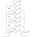
図12はコントローラの安全診断の動作を示す。コントローラ1、2は故障信号もしくは機能上の逸脱などの第1のエラー状況70を判定する。次いでコントローラ1、2は、そのエラー状況が危険を含むものであるか否かに関する推測71を行なう。必要ならば、コントローラはプログラム制御を作動禁止モード78に設定して、その場合、輸送システムを停止させる動作を行なうとともに、輸送システムの再始動を禁止する。エラー状況によっては作動禁止モード78への遷移が必要ない場合、コントローラは依然として、輸送システムを再始動できる停止状態79にプログラム制御が移行する輸送システムの停止を行なうか、または輸送システムが通常状態で作動し続けることを可能にする。コントローラは、次いで第2のエラー状況80を検出すると、再び同様の方法で推測を行ない、エラー状況が危険73、74を含むものであるか否かを判定し、そこでコントローラは、輸送システムを作動禁止モード78に設定るか、あるいは輸送システムの通常の停止79を行なうか、あるいは輸送システムの通常の作動を可能とする。第3のエラー状況81の後は、同様の推測手順75、76をもう一度繰り返し、この後、新たなエラー状況82が続くと、輸送システムを停止し、プログラム制御は、安全診断ソフトウエアに記述されているような作動禁止モード78か、あるいは再始動を許可する停止モード79のいずれかに移行する。
FIG. 12 shows the operation of the safety diagnosis of the controller.
以上、本発明を少数の実施例を参照して説明したが、本発明が上述の実施例だけに限定されることはなく、特許請求の範囲に記載する発明概念の範囲内で多くの他の実施例が可能であることは、当業者に明らかである。
Although the present invention has been described with reference to a few embodiments, the present invention is not limited to the above-described embodiments, and many other embodiments are within the scope of the inventive concept described in the claims. It will be apparent to those skilled in the art that embodiments are possible.
Claims (19)
・前記メッセージもしくは応答メッセージを送信するコントローラが読み取った速度および/または位置の測定データ
・前記メッセージもしくは応答メッセージを送信するコントローラにより検出された障害に関する通知
・少なくとも1つの制動装置への制御指令
を含み、
両コントローラは、前記制動装置への制御指令の間に、もしくは前記コントローラの速度および/または位置の測定データの間に差を検出すると、または前記検出された障害に関する通知を含むメッセージを受信すると、前記輸送システムを停止させる動作をそれぞれが独自に行なうよう構成されていることを特徴とする電力制御装置。 7. The power control apparatus according to claim 6, wherein both the message and the response message are at least the following data items:
- the control command message or the notification, at least one braking device related failure detected by the controller for transmitting the measurement data the message or the response message of the velocity and / or position controller has read to send a response message Including
When both controllers detect a difference during a control command to the braking device or between the speed and / or position measurement data of the controller or receive a message containing a notification about the detected fault, An electric power control device configured to independently perform an operation of stopping the transportation system.
Applications Claiming Priority (3)
| Application Number | Priority Date | Filing Date | Title |
|---|---|---|---|
| FI20070260A FI119508B (en) | 2007-04-03 | 2007-04-03 | Fail safe power control equipment |
| FI20070260 | 2007-04-03 | ||
| PCT/FI2008/000020 WO2008119870A1 (en) | 2007-04-03 | 2008-02-01 | Fail-safe power control apparatus |
Publications (3)
| Publication Number | Publication Date |
|---|---|
| JP2010523434A JP2010523434A (en) | 2010-07-15 |
| JP2010523434A5 JP2010523434A5 (en) | 2011-03-10 |
| JP5432886B2 true JP5432886B2 (en) | 2014-03-05 |
Family
ID=38009803
Family Applications (1)
| Application Number | Title | Priority Date | Filing Date |
|---|---|---|---|
| JP2010501539A Active JP5432886B2 (en) | 2007-04-03 | 2008-02-01 | Power control device |
Country Status (9)
| Country | Link |
|---|---|
| US (2) | US8096387B2 (en) |
| EP (2) | EP2132126A4 (en) |
| JP (1) | JP5432886B2 (en) |
| CN (1) | CN101715426B (en) |
| AU (1) | AU2008234802B2 (en) |
| CA (1) | CA2681780C (en) |
| DK (1) | DK2132127T3 (en) |
| FI (1) | FI119508B (en) |
| WO (2) | WO2008119869A1 (en) |
Families Citing this family (51)
| Publication number | Priority date | Publication date | Assignee | Title |
|---|---|---|---|---|
| KR100995188B1 (en) * | 2005-11-25 | 2010-11-17 | 미쓰비시덴키 가부시키가이샤 | Emergency stop system for elevator |
| JP5122570B2 (en) * | 2006-08-31 | 2013-01-16 | オーチス エレベータ カンパニー | Managing power fluctuations in elevator drive systems |
| KR101034926B1 (en) * | 2007-06-14 | 2011-05-17 | 미쓰비시덴키 가부시키가이샤 | Elevator |
| EP2022742B1 (en) * | 2007-08-07 | 2014-06-25 | ThyssenKrupp Elevator AG | Lift system |
| JP5383664B2 (en) * | 2008-04-15 | 2014-01-08 | 三菱電機株式会社 | Elevator equipment |
| US8000873B2 (en) * | 2008-05-12 | 2011-08-16 | Wabtec Holding Corp. | Braking system |
| EP2565145B1 (en) * | 2008-06-03 | 2015-03-04 | Otis Elevator Company | Elevator brake |
| CN102036898B (en) * | 2008-06-27 | 2013-05-01 | 三菱电机株式会社 | Elevator apparatus and operating method thereof |
| AU2010217638B2 (en) * | 2009-02-25 | 2016-07-28 | Inventio Ag | Elevator having a monitoring system |
| DE102009037347A1 (en) * | 2009-08-14 | 2011-02-17 | K.A. Schmersal Holding Gmbh & Co. Kg | Electronic security system for a lift |
| US8289734B2 (en) * | 2009-10-15 | 2012-10-16 | Ansaldo Sts Usa, Inc. | Output apparatus to output a vital output from two sources |
| KR101354728B1 (en) * | 2009-11-18 | 2014-01-22 | 미쓰비시덴키 가부시키가이샤 | Elevator device |
| DE102010002468A1 (en) * | 2010-03-01 | 2011-09-01 | Robert Bosch Gmbh | Method for stopping functional unit operated by controller in motor vehicle, involves operating functional unit by internal output circuit of controller |
| CN102781804B (en) * | 2010-03-12 | 2014-09-17 | 三菱电机株式会社 | Elevator safety control device |
| FI122183B (en) * | 2010-03-15 | 2011-09-30 | Kone Corp | Method and apparatus for starting the electric drive of an elevator |
| EP2571798B1 (en) * | 2010-05-21 | 2020-03-11 | Otis Elevator Company | Braking device |
| FI20106092A (en) * | 2010-10-21 | 2012-04-22 | Kone Corp | braking equipment |
| US9637349B2 (en) | 2010-11-04 | 2017-05-02 | Otis Elevator Company | Elevator brake including coaxially aligned first and second brake members |
| FI122473B (en) * | 2010-12-14 | 2012-02-15 | Kone Corp | Interface, transport system and method |
| EP2697146B1 (en) * | 2011-04-15 | 2020-10-21 | Otis Elevator Company | Elevator drive power supply control |
| JP2014531377A (en) * | 2011-10-06 | 2014-11-27 | オーチス エレベータ カンパニーOtis Elevator Company | Elevator brake control |
| US8807048B2 (en) * | 2012-04-28 | 2014-08-19 | Valentin Ivanov | Triple rail PRT transportation system |
| WO2013165995A1 (en) * | 2012-04-30 | 2013-11-07 | Thermo King Corporation | Transport refrigeration system controller to engine control unit interface |
| FI123506B (en) * | 2012-05-31 | 2013-06-14 | Kone Corp | Elevator control and elevator safety arrangement |
| IN2014DN09905A (en) | 2012-06-01 | 2015-08-07 | Otis Elevator Co | |
| IN2014DN10836A (en) * | 2012-06-26 | 2015-09-04 | Otis Elevator Co | |
| BR112015007078B1 (en) | 2012-10-30 | 2021-02-23 | Inventio Ag | motion monitoring system, elevator installation and process to monitor movement of an elevator cabin |
| FI125316B (en) | 2013-09-10 | 2015-08-31 | Kone Corp | Procedure for performing emergency stops and safety arrangements for lifts |
| CN105517934B (en) * | 2013-09-27 | 2018-01-02 | 三菱电机株式会社 | The control device of elevator |
| US9452909B2 (en) | 2013-10-25 | 2016-09-27 | Thyssenkrupp Elevator Ag | Safety related elevator serial communication technology |
| CN105960370A (en) * | 2013-12-05 | 2016-09-21 | 奥的斯电梯公司 | Motor drive for linear machines with distributed windings |
| AU2015318820B2 (en) * | 2014-09-15 | 2020-08-27 | Dti Group Limited | Identification of a pantograph represented in an image |
| US10745243B2 (en) * | 2014-10-21 | 2020-08-18 | Inventio Ag | Elevator comprising a decentralized electronic safety system |
| CN104590967B (en) * | 2015-01-26 | 2016-08-24 | 北京诺安舟应急缓降机械装置有限公司 | The safety system of a kind of high-rise rescue run equipment and using method thereof |
| US10689226B2 (en) * | 2015-02-04 | 2020-06-23 | Otis Elevator Company | Position determining system for multicar ropeless elevator system |
| WO2016126939A1 (en) * | 2015-02-05 | 2016-08-11 | Otis Elevator Company | Ropeless elevator control system |
| CN107534314B (en) | 2015-07-17 | 2021-06-08 | 慧与发展有限责任合伙企业 | System and method for current limiting |
| US11175638B2 (en) | 2015-11-09 | 2021-11-16 | Otis Elevator Company | Self-diagnostic electrical circuit |
| EP3214032B1 (en) * | 2016-03-03 | 2020-04-29 | Kone Corporation | Adjustable brake controller of an elevator brake, elevator brake and elevator |
| JP6555163B2 (en) * | 2016-03-17 | 2019-08-07 | 株式会社デンソー | Control system |
| US10427908B2 (en) * | 2016-04-15 | 2019-10-01 | Otis Elevator Company | Emergency mode operation of elevator system having linear propulsion system |
| WO2018010991A1 (en) * | 2016-07-14 | 2018-01-18 | Inventio Ag | Elevator with safety chain overlay control unit comprising a safety plc separately monitoring various safety switches for increasing a safety integrity level |
| ES2886612T3 (en) * | 2017-05-09 | 2021-12-20 | Kone Corp | Elevator Data Communication Arrangement |
| EP3403967B1 (en) * | 2017-05-15 | 2019-07-03 | KONE Corporation | A current cut-off arrangement of an elevator |
| CN108439119B (en) * | 2018-03-16 | 2019-08-13 | 淮南矿业(集团)有限责任公司 | A kind of control method and device of doube bridge mining elevator |
| JP7112240B2 (en) * | 2018-04-25 | 2022-08-03 | 株式会社日立産機システム | Power conversion system and power conversion method |
| DK3569540T3 (en) * | 2018-05-14 | 2022-04-04 | Kone Corp | Arrangement and method for dynamic braking of a permanent magnet motor and elevator with its use |
| US11840423B2 (en) | 2018-12-14 | 2023-12-12 | Otis Elevator Company | Hybrid energy storage system architectures |
| CN113677611B (en) * | 2019-03-29 | 2023-07-04 | 因温特奥股份公司 | Safety torque interruption device for interrupting torque generation of a drive machine of an elevator installation supplied by a power supply device |
| EP3966146A2 (en) * | 2019-05-07 | 2022-03-16 | Inventio AG | Drive of an elevator system |
| WO2021124419A1 (en) * | 2019-12-16 | 2021-06-24 | 三菱電機株式会社 | Control device for elevator |
Family Cites Families (26)
| Publication number | Priority date | Publication date | Assignee | Title |
|---|---|---|---|---|
| US3902573A (en) * | 1974-01-23 | 1975-09-02 | Donald E Grove | Elevator control system |
| US4207508A (en) * | 1977-04-14 | 1980-06-10 | Habisohn Victor J | Variable speed motor control system |
| JPS59144382A (en) * | 1983-02-04 | 1984-08-18 | Hitachi Ltd | Controller for ac elevator |
| JPS59149282A (en) * | 1983-02-12 | 1984-08-27 | 株式会社日立製作所 | Elevator controller |
| JP2503712B2 (en) * | 1990-03-08 | 1996-06-05 | 三菱電機株式会社 | Elevator speed control device |
| JPH03143884A (en) * | 1990-09-19 | 1991-06-19 | Hitachi Ltd | Control circuit of elevator |
| US5387769A (en) * | 1993-06-01 | 1995-02-07 | Otis Elevator Company | Local area network between an elevator system building controller, group controller and car controller, using redundant communication links |
| US5360952A (en) * | 1993-06-01 | 1994-11-01 | Otis Elevator Company | Local area network eleveator communications network |
| DE69633220T2 (en) * | 1995-01-31 | 2005-01-13 | Kone Corp. | CONTROL METHOD AND DEVICE FOR ELEVATOR MOTOR |
| JP3309648B2 (en) * | 1995-06-22 | 2002-07-29 | 三菱電機株式会社 | Elevator control device |
| JP3251844B2 (en) * | 1996-03-29 | 2002-01-28 | 三菱電機株式会社 | Elevator control device |
| US5893432A (en) * | 1996-12-31 | 1999-04-13 | Inventio Ag | Controlled emergency stop apparatus for elevators |
| US5929400A (en) * | 1997-12-22 | 1999-07-27 | Otis Elevator Company | Self commissioning controller for field-oriented elevator motor/drive system |
| US5900597A (en) * | 1998-03-19 | 1999-05-04 | Fernkas; Joseph Clifford | Elevator controller/solid state drive interface |
| KR100303011B1 (en) * | 1998-12-12 | 2002-05-09 | 장병우 | Operation control apparatus for elevator |
| US6173814B1 (en) * | 1999-03-04 | 2001-01-16 | Otis Elevator Company | Electronic safety system for elevators having a dual redundant safety bus |
| WO2002081352A1 (en) * | 2001-04-04 | 2002-10-17 | Toshiba Elevator Kabushiki Kaisha | Elevator control device |
| ATE348779T1 (en) * | 2001-07-04 | 2007-01-15 | Inventio Ag | METHOD FOR PREVENTING AN UNACCEPTABLY HIGH SPEED OF THE LOAD-RESISTING MEANS OF AN ELEVATOR |
| CN1216789C (en) * | 2001-12-24 | 2005-08-31 | 因温特奥股份公司 | Method for stopping operation of personnel transfer equipment |
| CN1239378C (en) * | 2001-12-24 | 2006-02-01 | 因温特奥股份公司 | Method for stopping personnel transport equipment operation |
| DK1510492T3 (en) * | 2003-08-25 | 2007-09-10 | Inventio Ag | Procedure for testing an elevator system and elevator system |
| WO2005049467A1 (en) * | 2003-11-19 | 2005-06-02 | Mitsubishi Denki Kabushiki Kaisha | Elevator controller |
| DE102004050647B4 (en) * | 2004-10-18 | 2014-11-20 | Siemens Aktiengesellschaft | Monitoring method for a drive device to a standstill, hereby corresponding monitoring device and hereby corresponding drive system |
| US7268514B2 (en) * | 2004-11-30 | 2007-09-11 | Rockwell Automation Technologies, Inc. | Motor control for stopping a load and detecting mechanical brake slippage |
| FR2880009B1 (en) * | 2004-12-27 | 2008-07-25 | Leroy Somer Moteurs | SAFETY DEVICE FOR ELEVATOR |
| DE602004029951D1 (en) * | 2004-12-31 | 2010-12-16 | Otis Elevator Co | RESCUE PROCESS CONTROL SYSTEM FOR LIFT |
-
2007
- 2007-04-03 FI FI20070260A patent/FI119508B/en not_active IP Right Cessation
-
2008
- 2008-01-17 WO PCT/FI2008/000005 patent/WO2008119869A1/en active Application Filing
- 2008-01-17 EP EP08701694.5A patent/EP2132126A4/en not_active Withdrawn
- 2008-02-01 CN CN200880018647XA patent/CN101715426B/en active Active
- 2008-02-01 EP EP08718490.9A patent/EP2132127B1/en active Active
- 2008-02-01 JP JP2010501539A patent/JP5432886B2/en active Active
- 2008-02-01 CA CA2681780A patent/CA2681780C/en not_active Expired - Fee Related
- 2008-02-01 AU AU2008234802A patent/AU2008234802B2/en not_active Ceased
- 2008-02-01 WO PCT/FI2008/000020 patent/WO2008119870A1/en active Application Filing
- 2008-02-01 DK DK08718490.9T patent/DK2132127T3/en active
-
2009
- 2009-10-02 US US12/572,800 patent/US8096387B2/en active Active
- 2009-10-02 US US12/572,933 patent/US7896135B2/en active Active
Also Published As
| Publication number | Publication date |
|---|---|
| CA2681780A1 (en) | 2008-10-09 |
| AU2008234802B2 (en) | 2013-03-21 |
| JP2010523434A (en) | 2010-07-15 |
| EP2132127A4 (en) | 2014-10-22 |
| CN101715426A (en) | 2010-05-26 |
| FI20070260A (en) | 2008-10-04 |
| FI119508B (en) | 2008-12-15 |
| US8096387B2 (en) | 2012-01-17 |
| WO2008119869A1 (en) | 2008-10-09 |
| EP2132127B1 (en) | 2017-08-23 |
| EP2132126A1 (en) | 2009-12-16 |
| CA2681780C (en) | 2015-08-11 |
| US20100038185A1 (en) | 2010-02-18 |
| DK2132127T3 (en) | 2017-10-16 |
| EP2132127A1 (en) | 2009-12-16 |
| US7896135B2 (en) | 2011-03-01 |
| AU2008234802A1 (en) | 2008-10-09 |
| EP2132126A4 (en) | 2014-10-22 |
| US20100032246A1 (en) | 2010-02-11 |
| WO2008119870A1 (en) | 2008-10-09 |
| FI20070260A0 (en) | 2007-04-03 |
| CN101715426B (en) | 2013-03-06 |
Similar Documents
| Publication | Publication Date | Title |
|---|---|---|
| JP5432886B2 (en) | Power control device | |
| JP4980423B2 (en) | Elevator equipment | |
| US7938231B2 (en) | Elevator apparatus having independent second brake control | |
| DK2496507T3 (en) | BRAKE DEVICE AND ELECTRICAL DRIVE FOR AN ELEVATOR SYSTEM AND ELEVATOR SYSTEM COMPREHENSIVE THESE | |
| JP2009154988A (en) | System for preventing traveling of elevator with door opened | |
| CN103249662A (en) | Method in connection with an emergency stop situation of an elevator, and also a safety arrangement for an elevator | |
| AU2019204558A1 (en) | An Elevator | |
| KR101189952B1 (en) | Elevator system | |
| JP5111502B2 (en) | Elevator equipment | |
| JP2011136837A (en) | Elevator system | |
| CN113748076B (en) | Driving device of elevator equipment | |
| WO2011010356A1 (en) | Control device for elevator | |
| WO2015151256A1 (en) | Elevator control device | |
| KR101246994B1 (en) | Elevator device | |
| JPS6239017Y2 (en) | ||
| JPH05201656A (en) | Controller for hydraulic elevator |
Legal Events
| Date | Code | Title | Description |
|---|---|---|---|
| A521 | Request for written amendment filed |
Free format text: JAPANESE INTERMEDIATE CODE: A821 Effective date: 20091023 |
|
| RD01 | Notification of change of attorney |
Free format text: JAPANESE INTERMEDIATE CODE: A7426 Effective date: 20091023 |
|
| A521 | Request for written amendment filed |
Free format text: JAPANESE INTERMEDIATE CODE: A523 Effective date: 20110118 |
|
| A621 | Written request for application examination |
Free format text: JAPANESE INTERMEDIATE CODE: A621 Effective date: 20110118 |
|
| A977 | Report on retrieval |
Free format text: JAPANESE INTERMEDIATE CODE: A971007 Effective date: 20120921 |
|
| A131 | Notification of reasons for refusal |
Free format text: JAPANESE INTERMEDIATE CODE: A131 Effective date: 20120925 |
|
| A521 | Request for written amendment filed |
Free format text: JAPANESE INTERMEDIATE CODE: A523 Effective date: 20121218 |
|
| A131 | Notification of reasons for refusal |
Free format text: JAPANESE INTERMEDIATE CODE: A131 Effective date: 20130702 |
|
| A521 | Request for written amendment filed |
Free format text: JAPANESE INTERMEDIATE CODE: A523 Effective date: 20131001 |
|
| TRDD | Decision of grant or rejection written | ||
| A01 | Written decision to grant a patent or to grant a registration (utility model) |
Free format text: JAPANESE INTERMEDIATE CODE: A01 Effective date: 20131112 |
|
| A61 | First payment of annual fees (during grant procedure) |
Free format text: JAPANESE INTERMEDIATE CODE: A61 Effective date: 20131206 |
|
| R150 | Certificate of patent or registration of utility model |
Ref document number: 5432886 Country of ref document: JP Free format text: JAPANESE INTERMEDIATE CODE: R150 |
|
| R250 | Receipt of annual fees |
Free format text: JAPANESE INTERMEDIATE CODE: R250 |
|
| R250 | Receipt of annual fees |
Free format text: JAPANESE INTERMEDIATE CODE: R250 |
|
| R250 | Receipt of annual fees |
Free format text: JAPANESE INTERMEDIATE CODE: R250 |
|
| R250 | Receipt of annual fees |
Free format text: JAPANESE INTERMEDIATE CODE: R250 |
|
| R250 | Receipt of annual fees |
Free format text: JAPANESE INTERMEDIATE CODE: R250 |
|
| R250 | Receipt of annual fees |
Free format text: JAPANESE INTERMEDIATE CODE: R250 |
|
| R250 | Receipt of annual fees |
Free format text: JAPANESE INTERMEDIATE CODE: R250 |
|
| R250 | Receipt of annual fees |
Free format text: JAPANESE INTERMEDIATE CODE: R250 |