JP5432880B2 - Brake system for vehicles - Google Patents
Brake system for vehicles Download PDFInfo
- Publication number
- JP5432880B2 JP5432880B2 JP2010257344A JP2010257344A JP5432880B2 JP 5432880 B2 JP5432880 B2 JP 5432880B2 JP 2010257344 A JP2010257344 A JP 2010257344A JP 2010257344 A JP2010257344 A JP 2010257344A JP 5432880 B2 JP5432880 B2 JP 5432880B2
- Authority
- JP
- Japan
- Prior art keywords
- brake
- vehicle
- hydraulic pressure
- input device
- electric
- Prior art date
- Legal status (The legal status is an assumption and is not a legal conclusion. Google has not performed a legal analysis and makes no representation as to the accuracy of the status listed.)
- Active
Links
Images


Landscapes
- Braking Systems And Boosters (AREA)
- Valves And Accessory Devices For Braking Systems (AREA)
- Regulating Braking Force (AREA)
Description
本発明は、車両用ブレーキシステムに関する。 The present invention relates to a vehicle brake system.
従来、車両(自動車)用のブレーキシステムとしては、例えば、負圧式ブースタや油圧式ブースタ等の倍力装置を備えるものが知られている。また、近年では、電動モータを倍力源として利用する電動倍力装置が知られている(例えば、特許文献1参照)。 Conventionally, as a brake system for a vehicle (automobile), for example, a system including a booster such as a negative pressure booster or a hydraulic booster is known. In recent years, an electric booster that uses an electric motor as a boost source is known (see, for example, Patent Document 1).
この特許文献1に開示された電動倍力装置は、ブレーキペダルの操作によって進退動作する主ピストンと、この主ピストンと相対変位可能に外嵌された筒状のブースタピストンと、このブースタピストンを進退動作させる電動モータとを備えて構成されている。 The electric booster disclosed in Patent Document 1 includes a main piston that moves forward and backward by operating a brake pedal, a cylindrical booster piston that is externally fitted so as to be relatively displaceable with the main piston, and a forward and backward movement of the booster piston. And an electric motor to be operated.
この電動倍力装置によれば、主ピストンとブースタピストンとをマスタシリンダのピストンとし、それぞれの前端部をマスタシリンダの圧力室に臨ませることで、操作者によってブレーキペダルから主ピストンに入力される推力と、電動モータからブースタピストンに入力されるブースタ推力とによって、ブレーキ液圧をマスタシリンダ内に発生させることができる。 According to this electric booster, the main piston and the booster piston are used as the pistons of the master cylinder, and the front ends thereof face the pressure chambers of the master cylinder. The brake fluid pressure can be generated in the master cylinder by the thrust and the booster thrust input from the electric motor to the booster piston.
しかしながら、特許文献1に開示された電動倍力装置では、ブレーキペダルから入力される液圧発生機構と、電動モータから入力される液圧発生機構とを一体に構成しているため、装置全体が大型化する傾向にあり、レイアウトの自由度が損なわれるという問題があった。 However, in the electric booster disclosed in Patent Document 1, since the hydraulic pressure generation mechanism input from the brake pedal and the hydraulic pressure generation mechanism input from the electric motor are integrally configured, the entire apparatus is There is a problem in that the size tends to increase and the degree of freedom in layout is impaired.
本発明は、前記従来の問題を解決するものであり、レイアウトの自由度を高めることができる車両用ブレーキシステムを提供することを課題とする。 This invention solves the said conventional problem, and makes it a subject to provide the brake system for vehicles which can raise the freedom degree of a layout.
前記課題を解決した本発明の車両用ブレーキシステムは、操作者のブレーキ操作が入力される入力装置と、少なくとも前記ブレーキ操作に応じた電気信号に基づいてブレーキ液圧を発生する電動ブレーキアクチュエータと、前記電動ブレーキアクチュエータで発生した前記ブレーキ液圧に基づいて車両の挙動の安定化を支援する車両挙動安定化装置と、を備え、前記入力装置、前記電動ブレーキアクチュエータ及び前記車両挙動安定化装置は、ダッシュボードの前方において区画された動力装置の搭載室に、互いに分離して配置され、前記入力装置、前記電動ブレーキアクチュエータ及び前記車両挙動安定化装置は、ブレーキ液を輸送する配管で接続されている車両用ブレーキシステムであって、前記入力装置は、前記電動ブレーキアクチュエータの異常時にホイールシリンダに液圧を発生可能なマスタシリンダを備え、前記マスタシリンダの出力ポートを、前記車両挙動安定化装置と、前記電動ブレーキアクチュエータとのそれぞれに、独立の配管により接続したことを特徴とする。 The vehicle brake system of the present invention that has solved the above problems includes an input device to which an operator's brake operation is input, an electric brake actuator that generates brake fluid pressure based on at least an electric signal corresponding to the brake operation, A vehicle behavior stabilization device that supports stabilization of vehicle behavior based on the brake fluid pressure generated by the electric brake actuator, and the input device, the electric brake actuator, and the vehicle behavior stabilization device include: The input device, the electric brake actuator, and the vehicle behavior stabilization device are connected to each other by piping for transporting brake fluid. A brake system for a vehicle, wherein the input device includes the electric brake actuator. A master cylinder capable of generating a hydraulic pressure in the wheel cylinder when a motor abnormality occurs, and an output port of the master cylinder is connected to each of the vehicle behavior stabilization device and the electric brake actuator by independent piping. It is characterized by that.
このような本発明の車両用ブレーキシステムによれば、入力装置と電動ブレーキアクチュエータと車両挙動安定化装置とをそれぞれ分離して(別体にて)構成したので、入力装置、電動ブレーキアクチュエータ、車両挙動安定化装置のそれぞれのサイズを小型化することができ、レイアウトの自由度を高めることができる。つまり、動力装置の搭載室内には、エンジン及び/又は走行モータ、トランスミッション、ラジエータ等の冷却系、低圧バッテリなど各種の装置が搭載されるため、必然的に大きな空スペース(設置スペース)を確保することが難しくなる。しかし、本発明のように入力装置と電動ブレーキアクチュエータと車両挙動安定化装置とをそれぞれ分離して構成することで、個々の装置のサイズを小さくすることができ、大きな空スペースを確保する必要がなくなり、狭い空スペースであっても各装置を搭載することが可能になる。 According to such a vehicle brake system of the present invention, since the input device, the electric brake actuator, and the vehicle behavior stabilization device are configured separately (separately), the input device, the electric brake actuator, the vehicle The size of each of the behavior stabilization devices can be reduced, and the degree of freedom in layout can be increased. In other words, various devices such as a cooling system such as an engine and / or a traveling motor, a transmission, a radiator, and a low-voltage battery are mounted in the power device mounting chamber, so that a large empty space (installation space) is necessarily secured. It becomes difficult. However, by separately configuring the input device, the electric brake actuator, and the vehicle behavior stabilization device as in the present invention, it is possible to reduce the size of each device and to secure a large empty space. Each device can be mounted even in a narrow empty space.
また、本発明の車両用ブレーキシステムによれば、入力装置と電動ブレーキアクチュエータと車両挙動安定化装置とをそれぞれ分離して構成するので、各装置の部品に対して従来品を流用し易くなる。 In addition, according to the vehicle brake system of the present invention, the input device, the electric brake actuator, and the vehicle behavior stabilization device are configured separately from each other, so that the conventional product can be easily used for the components of each device.
また、本発明の車両用ブレーキシステムによれば、入力装置と電動ブレーキアクチュエータとをそれぞれ分離して構成するので、音や振動の発生源となることがある電動ブレーキアクチュエータを運転者から離して配置することができ、運転者に音や振動による違和感(不快感)を与えるのを防止することができる。 Further, according to the vehicle brake system of the present invention, the input device and the electric brake actuator are configured separately from each other, so that the electric brake actuator that may be a source of noise and vibration is arranged away from the driver. It is possible to prevent the driver from feeling uncomfortable (uncomfortable) due to sound or vibration.
また、本発明の車両用ブレーキシステムによれば、入力装置と電動ブレーキアクチュエータとをそれぞれ分離して構成するので、これらを配管で接続する際に、その接続態様にバリエーションを持たせることができる。したがって、本発明の車両用ブレーキシステムによれば、車両に対する搭載性に優れる車両用ブレーキシステムを提供することができる。 Moreover, according to the vehicle brake system of the present invention, the input device and the electric brake actuator are configured separately from each other. Therefore, when these are connected by piping, the connection mode can be varied. Therefore, according to the vehicle brake system of the present invention, it is possible to provide a vehicle brake system that is excellent in mountability on a vehicle.
また、本発明の車両用ブレーキシステムによれば、マスタシリンダの出力ポートを、車両挙動安定化装置と、電動ブレーキアクチュエータとのそれぞれに、独立の配管により接続する。そのため、前記したように、例えば、各車種の空スペース(設置スペース)に応じて、車両挙動安定化装置と、電動ブレーキアクチュエータとを分離して配置した場合であっても、配管設計をシンプルに行うことができる。また、独立の配管で構成されているので、例えば配管の取替時において配管の交換を個別に行うことができる。 Further, according to the vehicle brake system of the present invention, the output port of the master cylinder is connected to the vehicle behavior stabilization device and the electric brake actuator by independent piping. Therefore, as described above, for example, even when the vehicle behavior stabilization device and the electric brake actuator are separately arranged according to the empty space (installation space) of each vehicle type, the piping design is simplified. It can be carried out. Moreover, since it is comprised by independent piping, piping replacement | exchange can be performed separately, for example at the time of replacement | exchange of piping.
本発明によれば、レイアウトの自由度を高めることができる車両用ブレーキシステムを提供できる。 ADVANTAGE OF THE INVENTION According to this invention, the brake system for vehicles which can raise the freedom degree of a layout can be provided.
次に、本発明の実施形態について、適宜図面を参照しながら詳細に説明する。
以下の実施形態では、電気信号を伝達してブレーキを作動させるバイ・ワイヤ(By Wire)式のブレーキシステムと、フェイルセイフ時(異常時)用として、油圧を伝達してブレーキを作動させる油圧式のブレーキシステムの双方を備えて構成されるものを例にとって説明する。
Next, embodiments of the present invention will be described in detail with reference to the drawings as appropriate.
In the following embodiments, a by-wire type brake system that transmits an electric signal to operate a brake, and a hydraulic type that transmits hydraulic pressure to operate the brake for fail-safe (when abnormal) A description will be given by taking as an example a configuration including both of the brake systems.
(第1実施形態)
図1に示すように、第1実施形態に係る車両用ブレーキシステム10Aは、基本的に、操作者によってブレーキ操作が入力される入力装置14と、少なくともブレーキ操作に応じた電気信号に基づいてブレーキ液圧を発生させるモータシリンダ装置(電動ブレーキアクチュエータ)16と、このモータシリンダ装置16で発生したブレーキ液圧に基づいて車両挙動の安定化を支援するビークルスタビリティアシスト装置18(車両挙動安定化装置、以下、VSA装置18という、VSA;登録商標)とを備え、入力装置14、モータシリンダ装置16及びVSA装置18が、車両VのエンジンルームR(動力装置の搭載室)内に配置されて構成されている。
本実施形態に係る車両用ブレーキシステム10Aは、入力装置14、モータシリンダ装置16及びVSA装置18がエンジンルームRで互いに分離して配置されると共に、入力装置16を構成する後記マスタシリンダ34(図2参照)の出力ポート54a、54b(図2参照)を、VSA装置18と、モータシリンダ装置16とのそれぞれに、独立の配管チューブ22b、22c、22e、22fにより接続したことを主な特徴点とする。
(First embodiment)
As shown in FIG. 1, the vehicle brake system 10 </ b> A according to the first embodiment basically includes an input device 14 to which a brake operation is input by an operator, and a brake based on at least an electric signal corresponding to the brake operation. A motor cylinder device (electric brake actuator) 16 that generates hydraulic pressure, and a vehicle stability assist device 18 (vehicle behavior stabilization device) that supports stabilization of vehicle behavior based on the brake hydraulic pressure generated by the
In the vehicle brake system 10A according to the present embodiment, the input device 14, the
なお、モータシリンダ装置16は、運転者のブレーキ操作に応じた電気信号だけではなく、他の物理量に応じた電気信号に基づいて液圧を発生させる手段を更に備えていてもよい。他の物理量に応じた電気信号とは、例えば、自動ブレーキシステムのような、運転者のブレーキ操作によらずに、ECU(Electronic Control Unit)が車両Vの周囲の状況をセンサ等で判断して、車両Vの衝突を回避するための信号を意味している。
The
本実施形態でのエンジンルームRは、ダッシュボード2の前方において区画され、車幅方向の左右両側に車両Vの前後方向に沿って延在する一対のフロントサイドフレーム1a、1bと、前記一対のフロントサイドフレーム1a、1bの上方に所定間隔離間して車両Vの前後方向に沿って延在する一対のアッパメンバ1c、1dと、前記一対のフロントサイドフレーム1a、1bの前端部に連結されて複数の部材によって略矩形状の枠体からなるバルクヘッド連結体1eと、前記一対のアッパメンバ1c、1dの前後方向の後ろ寄りに図示しないストラットを支持するダンパハウジング1f、1gとで囲まれて構成されている。なお、図示しないストラットは、例えばショックを吸収するコイルスプリングと振動を低減するショックアブソーバとによって前輪ダンパとして構成されている。
The engine room R in this embodiment is partitioned in front of the
また、エンジンルームRには、車両用ブレーキシステム10Aと共に、動力装置3などの構造物が搭載されている。動力装置3としては、例えばエンジン3aと電動機(走行モータ)3bとトランスミッション(図示省略)とを組み合わされたハイブリッド自動車用のものであり、エンジンルームR内の空間の略中央部に配置されている。なお、エンジン3a及び電動機3bによる動力は、図示しない動力伝達機構を介して左右の前輪を駆動するように構成されている。また、車両Vの車室Cの床下や車室Cの後方には、電動機3bに電力を供給し、電動機3bから電力(回生電力)を充電する図示しない高圧バッテリ(リチウムイオン電池など)が搭載されている。なお、車両は、前輪駆動、後輪駆動、四輪駆動のいずれであってもよい。
In the engine room R, a structure such as the
なお、エンジンルームR内に搭載された動力装置3の周囲には、車両用ブレーキシステム10Aの他に、図示しないランプ類などに電力を供給する低圧バッテリを含む電気系、吸気系、排気系、冷却系など各種の構造物(補機)が取り付けられている。
Around the
本実施形態での入力装置14は、右ハンドル車に適用するものであり、ダッシュボード2の車幅方向の右側に後記するスタッドボルト303(図3参照)を介して固定され、ブレーキペダル12(図2参照)と連結されるプッシュロッド42(図2参照)がダッシュボード2を貫通して車室C側に突出するように構成されている。
The input device 14 in the present embodiment is applied to a right-hand drive vehicle, and is fixed to a right side of the
モータシリンダ装置16は、図1に示すように、入力装置14とは逆側の車幅方向の左側に配置され、例えば左側のフロントサイドフレーム1aに図示しないブラケットを介して取り付けられている。具体的には、モータシリンダ装置16は、ブラケットに対して弾性(フローティング)支持され、ブラケットがフロントサイドフレーム1aに対してボルトなどの締結部材を介して締結されている。これにより、モータシリンダ装置16の作動時に発生する振動等を吸収できるようになっている。
As shown in FIG. 1, the
VSA装置18は、例えば、ブレーキ時の車輪ロックを防ぐABS(アンチロック・ブレーキ・システム)機能、加速時などの車輪空転を防ぐTCS(トラクション・コントロール・システム)機能、旋回時の横すべりを抑制する機能などを備えて構成され、車幅方向の右端の前側に、例えばブラケットを介して車体に取り付けられている。なお、VSA装置18に代えて、ブレーキ時の車輪ロックを防ぐABS機能のみを有するABS装置を接続してもよい。
The
これら入力装置14、モータシリンダ装置16、及びVSA装置18は、例えば、金属製の管材で形成された液圧路によって接続されていると共に、バイ・ワイヤ式のブレーキシステムとして、入力装置14とモータシリンダ装置16とは、図示しないハーネスで電気的に接続されている。
The input device 14, the
すなわち、入力装置14とVSA装置18とは、第1液圧系統70a(図2参照)として、配管チューブ22cを介して互いに接続され、第2液圧系統70b(図2参照)として、配管チューブ22fを介して互いに接続されている。
That is, the input device 14 and the
また、入力装置14とモータシリンダ装置16とは、第1液圧系統70a(図2参照)として、配管チューブ22bを介して接続され、第2液圧系統70b(図2参照)として、配管チューブ22eを介して接続されている。
The input device 14 and the
図2を参照して液圧路について説明すると、入力装置14の接続ポート20a1と、モータシリンダ装置16の出力ポート24aとが配管チューブ22bによって接続され、入力装置14の接続ポート20a2と、VSA装置18の導入ポート26aとが配管チューブ22cによって接続されている。
The hydraulic path will be described with reference to FIG. 2. The connection port 20a1 of the input device 14 and the
また、入力装置14の接続ポート20b1と、モータシリンダ装置16の他の出力ポート24bとが配管チューブ22eによって接続され、入力装置14の接続ポート20b2と、VSA装置18の他の導入ポート26bとが配管チューブ22fによって接続されている。
Further, the connection port 20b1 of the input device 14 and the
VSA装置18には、複数の導出ポート28a〜28dが設けられる。第1導出ポート28aは、配管チューブ22gによって右側前輪に設けられたディスクブレーキ機構30aのホイールシリンダ32FRと接続される。第2導出ポート28bは、配管チューブ22hによって左側後輪に設けられたディスクブレーキ機構30bのホイールシリンダ32RLと接続される。第3導出ポート28cは、配管チューブ22iによって右側後輪に設けられたディスクブレーキ機構30cのホイールシリンダ32RRと接続される。第4導出ポート28dは、配管チューブ22jによって左側前輪に設けられたディスクブレーキ機構30dのホイールシリンダ32FLと接続される。
The
この場合、各導出ポート28a〜28dに接続される配管チューブ22g〜22jによってブレーキ液がディスクブレーキ機構30a〜30dの各ホイールシリンダ32FR、32RL、32RR、32FLに対して供給され、各ホイールシリンダ32FR、32RL、32RR、32FL内の液圧が上昇することにより、各ホイールシリンダ32FR、32RL、32RR、32FLが作動し、対応する車輪(右側前輪、左側後輪、右側後輪、左側前輪)に対して制動力が付与される。
In this case, the brake fluid is supplied to the wheel cylinders 32FR, 32RL, 32RR, 32FL of the
なお、車両用ブレーキシステム10Aは、本実施形態で想定しているハイブリッド自動車のほか、例えば、エンジン(内燃機関)のみによって駆動される自動車、電気自動車、燃料電池自動車等を含む各種車両に対して搭載可能に設けられる。 In addition to the hybrid vehicle assumed in the present embodiment, the vehicle brake system 10A is used for various vehicles including, for example, a vehicle driven only by an engine (internal combustion engine), an electric vehicle, and a fuel cell vehicle. It is provided so that it can be mounted.
入力装置14は、運転者によるブレーキペダル12の操作によって液圧を発生可能なタンデム式のマスタシリンダ34と、前記マスタシリンダ34に付設された第1リザーバ36とを有する。このマスタシリンダ34のシリンダチューブ38内には、前記シリンダチューブ38の軸方向に沿って所定間隔離間する2つのピストン40a、40bが摺動自在に配設される。一方のピストン40aは、ブレーキペダル12に近接して配置され、プッシュロッド42を介してブレーキペダル12と連結される。また、他方のピストン40bは、一方のピストン40aよりもブレーキペダル12から離間して配置される。
The input device 14 includes a tandem master cylinder 34 that can generate hydraulic pressure by operating the
この一方及び他方のピストン40a、40bの外周面には、環状段部を介して一対のピストンパッキン44a、44bがそれぞれ装着される。一対のピストンパッキン44a、44bの間には、それぞれ、後記するサプライポート46a、46bと連通する背室48a、48bが形成される。また、一方及び他方のピストン40a、40bとの間には、ばね部材50aが配設され、他方のピストン40bとシリンダチューブ38の側端部との間には、他のばね部材50bが配設される。
なお、ピストン40a、40bの外周面にピストンパッキン44a、44bを設ける代わりに、シリンダチューブ38の内周面にパッキンを配設してもよい。
A pair of
Instead of providing
マスタシリンダ34のシリンダチューブ38には、2つのサプライポート46a、46bと、2つのリリーフポート52a、52bと、2つの出力ポート54a、54bとが設けられる。この場合、各サプライポート46a(46b)及び各リリーフポート52a(52b)は、それぞれ合流して第1リザーバ36内の図示しないリザーバ室と連通するように設けられる。
The
また、マスタシリンダ34のシリンダチューブ38内には、運転者(操作者)がブレーキペダル12を踏み込む踏力に対応したブレーキ液圧を制御する第1圧力室56a及び第2圧力室56bが設けられる。第1圧力室56aは、出力ポート54a、第1液圧路58a及び連結点A1を介して各接続ポート20a1、20a2と連通するように設けられ、第2圧力室56bは、出力ポート54b、第2液圧路58b及び連結点A2を介して各接続ポート20b1、20b2と連通するように設けられる。
Further, in the
マスタシリンダ34と連結点A1との間であって、第1液圧路58aの上流側には圧力センサPmが配設されると共に、第1液圧路58aの下流側には、ノーマルオープンタイプ(常開型)のソレノイドバルブからなる第1遮断弁60aが設けられる。この圧力センサPmは、第1液圧路58a上において、第1遮断弁60aよりもマスタシリンダ34側の上流の液圧を検知するものである。
A pressure sensor Pm is disposed between the master cylinder 34 and the connection point A1 and upstream of the first
マスタシリンダ34と連結点A2との間であって、第2液圧路58bの上流側には、ノーマルオープンタイプ(常開型)のソレノイドバルブからなる第2遮断弁60bが設けられると共に、第2液圧路58bの下流側には、圧力センサPpが設けられる。この圧力センサPpは、第2液圧路58b上において、第2遮断弁60bよりもホイールシリンダ32FR、32RL、32RR、32FL側の下流側の液圧を検知するものである。
A second shut-off
この第1遮断弁60a及び第2遮断弁60bにおけるノーマルオープンとは、ノーマル位置(非通電時の弁体の位置)が開位置の状態(常時開)となるように構成されたバルブをいう。なお、図2において、第1遮断弁60a及び第2遮断弁60bは、通電時(励磁時)の状態を示している(後記する第3遮断弁62も同様)。
The normal open in the first shut-off
マスタシリンダ34と第2遮断弁60bとの間の第2液圧路58bには、前記第2液圧路58bから分岐する分岐液圧路58cが設けられ、前記分岐液圧路58cには、ノーマルクローズタイプ(常閉型)のソレノイドバルブからなる第3遮断弁62と、ストロークシミュレータ64とが直列に接続される。この第3遮断弁62におけるノーマルクローズとは、ノーマル位置(非通電時の弁体の位置)が閉位置の状態となるように構成されたバルブをいう。
A branch
このストロークシミュレータ64は、第1遮断弁60a及び第2遮断弁60bの遮断時に、ブレーキペダル12の操作に応じた操作反力とストロークを生じさせる装置である。このストロークシミュレータ64は、第2遮断弁60bよりもマスタシリンダ34側で第2液圧路58bから分岐する分岐液圧路58c及びポート65aを介して設けられている。つまり、ストロークシミュレータ64の液圧室65には、マスタシリンダ34の第2圧力室56bから導出されるブレーキ液(ブレーキフルード)が、第2液圧路58b、分岐液圧路58c及びポート65aを介して供給されるようになっている。
The
また、ストロークシミュレータ64は、互いに直列に配置されたばね定数の高い第1リターンスプリング66aとばね定数の低い第2リターンスプリング66bと、前記第1及び第2リターンスプリング66a、66bによって付勢されるシミュレータピストン68とを備え、ブレーキペダル12の踏み込み前期時にペダル反力の増加勾配を低く設定し、踏み込み後期時にペダル反力を高く設定してブレーキペダル12のペダルフィーリングを既存のマスタシリンダと同等になるように設けられている。
The
液圧路は、大別すると、マスタシリンダ34の第1圧力室56aと複数のホイールシリンダ32FR、32RLとを接続する第1液圧系統70aと、マスタシリンダ34の第2圧力室56bと複数のホイールシリンダ32RR、32FLとを接続する第2液圧系統70bとから構成される。
The hydraulic pressure path is roughly divided into a first
第1液圧系統70aは、前記したように、入力装置14におけるマスタシリンダ34(シリンダチューブ38)の出力ポート54aと各接続ポート20a1、20a2とを接続する第1液圧路58aと、入力装置14の接続ポート20a1とモータシリンダ装置16の出力ポート24aとを接続する配管チューブ22bと、モータシリンダ装置16の出力ポート24aとVSA装置18の導入ポート26aとを入力装置14の接続ポート20a2を介して接続する配管チューブ22cと、VSA装置18の導出ポート28a、28bと各ホイールシリンダ32FR、32RLとをそれぞれ接続する配管チューブ22g、22hとによって構成される。
As described above, the first
第2液圧系統70bは、前記したように、入力装置14におけるマスタシリンダ34(シリンダチューブ38)の出力ポート54bと各接続ポート20b1、20b2とを接続する第2液圧路58bと、入力装置14の接続ポート20b1とモータシリンダ装置16の出力ポート24bとを接続する配管チューブ22eと、モータシリンダ装置16の出力ポート24bとVSA装置18の導入ポート26bとを入力装置14の接続ポート20b2を介して接続する配管チューブ22fと、VSA装置18の導出ポート28c、28dと各ホイールシリンダ32RR、32FLとをそれぞれ接続する配管チューブ22i、22jとによって構成される。
As described above, the second
この結果、液圧路が第1液圧系統70aと第2液圧系統70bとによって構成されることにより、各ホィールシリンダ32FR、32RLと各ホィールシリンダ32RR、32FLとをそれぞれ独立して作動させ、相互に独立した制動力を発生させることができる。
As a result, the hydraulic path is constituted by the first
モータシリンダ装置16は、電動モータ72を含むアクチュエータ機構74と、前記アクチュエータ機構74によって付勢されるシリンダ機構76とを有する。
The
アクチュエータ機構74は、電動モータ72の出力軸側に設けられ、複数のギヤが噛合して電動モータ72の回転駆動力を伝達するギヤ機構(減速機構)78と、前記ギヤ機構78を介して前記回転駆動力が伝達されることにより軸方向に沿って進退動作するボールねじ軸80a及びボール80bを含むボールねじ構造体80とを有する。
The
シリンダ機構76は、略円筒状のシリンダ本体82と、前記シリンダ本体82に付設された第2リザーバ84とを有する。第2リザーバ84は、入力装置14のマスタシリンダ34に付設された第1リザーバ36と配管チューブ86で接続され、第1リザーバ36内に貯留されたブレーキ液が配管チューブ86を介して第2リザーバ84内に供給されるように設けられる。
The
シリンダ本体82内には、前記シリンダ本体82の軸方向に沿って所定間隔離間する第1スレーブピストン88a及び第2スレーブピストン88bが摺動自在に配設される。第1スレーブピストン88aは、ボールねじ構造体80側に近接して配置され、ボールねじ軸80aの一端部に当接してこのボールねじ軸80aと一体的に矢印X1又はX2方向に変位する。また、第2スレーブピストン88bは、第1スレーブピストン88aよりもボールねじ構造体80側から離間して配置される。
In the
この第1及び第2スレーブピストン88a、88bの外周面には、環状段部を介して一対のスレーブピストンパッキン90a、90bがそれぞれ装着される。一対のスレーブピストンパッキン90a、90bの間には、それぞれ、後記するリザーバポート92a、92bとそれぞれ連通する第1背室94a及び第2背室94bが形成される。また、第1及び第2スレーブピストン88a、88bとの間には、第1リターンスプリング96aが配設され、第2スレーブピストン88bとシリンダ本体82の側端部と間には、第2リターンスプリング96bが配設される。
A pair of
シリンダ機構76のシリンダ本体82には、2つのリザーバポート92a、92bと、2つの出力ポート24a、24bとが設けられる。この場合、リザーバポート92a(92b)は、第2リザーバ84内の図示しないリザーバ室と連通するように設けられる。
The
また、シリンダ本体82内には、出力ポート24aからホイールシリンダ32FR、32RL側へ出力されるブレーキ液圧を制御する第1液圧室98aと、他の出力ポート24bからホイールシリンダ32RR、32FL側へ出力されるブレーキ液圧を制御する第2液圧室98bが設けられる。
Further, in the
なお、第1スレーブピストン88aと第2スレーブピストン88bとの間には、第1スレーブピストン88aと第2スレーブピストン88bの最大ストローク(最大変位距離)と最小ストローク(最小変位距離)とを規制する規制手段100が設けられる。さらに、第2スレーブピストン88bには、前記第2スレーブピストン88bの摺動範囲を規制して、第1スレーブピストン88a側へのオーバーリターンを阻止するストッパピン102が設けられ、これによって、特にマスタシリンダ34で発生したブレーキ液圧で制動するときのバックアップ時において、1系統の失陥時に他の系統の失陥が防止される。
The maximum stroke (maximum displacement distance) and the minimum stroke (minimum displacement distance) of the
VSA装置18は、周知のものからなり、右側前輪及び左側後輪のディスクブレーキ機構30a、30b(ホイールシリンダ32FR、ホイールシリンダ32RL)に接続された第1液圧系統70aを制御する第1ブレーキ系110aと、右側後輪及び左側前輪のディスクブレーキ機構30c、30d(ホイールシリンダ32RR、ホイールシリンダ32FL)に接続された第2液圧系統70bを制御する第2ブレーキ系110bとを有する。なお、第1ブレーキ系110aは、左側前輪及び右側前輪に設けられたディスクブレーキ機構に接続された液圧系統からなり、第2ブレーキ系110bは、左側後輪及び右側後輪に設けられたディスクブレーキ機構に接続された液圧系統であってもよい。更に、第1ブレーキ系110aは、車体片側の右側前輪及び右側後輪に設けられたディスクブレーキ機構に接続された液圧系統からなり、第2ブレーキ系110bは、車体片側の左側前輪及び左側後輪に設けられたディスクブレーキ機構に接続された液圧系統であってもよい。
The
この第1ブレーキ系110a及び第2ブレーキ系110bは、それぞれ同一構造からなるため、第1ブレーキ系110aと第2ブレーキ系110bで対応するものには同一の参照符号を付していると共に、第1ブレーキ系110aの説明を中心にして、第2ブレーキ系110bの説明を括弧書きで付記する。
Since the
第1ブレーキ系110a(第2ブレーキ系110b)は、ホイールシリンダ32FR、32RL(32RR、32FL)に対して、共通する第1共通液圧路112及び第2共通液圧路114を有する。VSA装置18は、導入ポート26aと第1共通液圧路112との間に配置されたノーマルオープンタイプのソレノイドバルブからなるレギュレータバルブ116と、前記レギュレータバルブ116と並列に配置され導入ポート26a側から第1共通液圧路112側へのブレーキ液の流通を許容する(第1共通液圧路112側から導入ポート26a側へのブレーキ液の流通を阻止する)第1チェックバルブ118と、第1共通液圧路112と第1導出ポート28aとの間に配置されたノーマルオープンタイプのソレノイドバルブからなる第1インバルブ120と、前記第1インバルブ120と並列に配置され第1導出ポート28a側から第1共通液圧路112側へのブレーキ液の流通を許容する(第1共通液圧路112側から第1導出ポート28a側へのブレーキ液の流通を阻止する)第2チェックバルブ122と、第1共通液圧路112と第2導出ポート28bとの間に配置されたノーマルオープンタイプのソレノイドバルブからなる第2インバルブ124と、前記第2インバルブ124と並列に配置され第2導出ポート28b側から第1共通液圧路112側へのブレーキ液の流通を許容する(第1共通液圧路112側から第2導出ポート28b側へのブレーキ液の流通を阻止する)第3チェックバルブ126とを備える。
The
さらに、VSA装置18は、第1導出ポート28aと第2共通液圧路114との間に配置されたノーマルクローズタイプのソレノイドバルブからなる第1アウトバルブ128と、第2導出ポート28bと第2共通液圧路114との間に配置されたノーマルクローズタイプのソレノイドバルブからなる第2アウトバルブ130と、第2共通液圧路114に接続されたリザーバ132と、第1共通液圧路112と第2共通液圧路114との間に配置されて第2共通液圧路114側から第1共通液圧路112側へのブレーキ液の流通を許容する(第1共通液圧路112側から第2共通液圧路114側へのブレーキ液の流通を阻止する)第4チェックバルブ134と、前記第4チェックバルブ134と第1共通液圧路112との間に配置されて第2共通液圧路114側から第1共通液圧路112側へブレーキ液を供給するポンプ136と、このポンプ136の前後に設けられる吸入弁138及び吐出弁140と、ポンプ136を駆動するモータMと、第2共通液圧路114と導入ポート26aとの間に配置されるサクションバルブ142とを備える。
Further, the
なお、第1ブレーキ系110aにおいて、導入ポート26aに近接する液圧路上には、モータシリンダ装置16の出力ポート24aから出力され、前記モータシリンダ装置16の第1液圧室98aで制御されたブレーキ液圧を検知する圧力センサPhが設けられる。各圧力センサPs、Pp、Phで検出された検出信号は、図示しない制御手段に導入される。
In the
本実施形態に係る車両用ブレーキシステム10Aは、基本的に以上のように構成されるものであり、次にその作用効果について説明する。 The vehicle brake system 10A according to the present embodiment is basically configured as described above, and the operation and effect thereof will be described next.
車両用ブレーキシステム10Aが正常に機能する正常時には、ノーマルオープンタイプのソレノイドバルブからなる第1遮断弁60a及び第2遮断弁60bが励磁で弁閉状態となり、ノーマルクローズタイプのソレノイドバルブからなる第3遮断弁62が励磁で弁開状態となる。従って、第1遮断弁60a及び第2遮断弁60bによって第1液圧系統70a及び第2液圧系統70bが遮断されているため、入力装置14のマスタシリンダ34で発生したブレーキ液圧がディスクブレーキ機構30a〜30dのホイールシリンダ32FR、32RL、32RR、32FLに伝達されることはない。
When the vehicle brake system 10A is functioning normally, the first shut-off
このとき、マスタシリンダ34の第2圧力室56bで発生したブレーキ液圧は、分岐液圧路58c及び弁開状態にある第3遮断弁62を経由してストロークシミュレータ64の液圧室65に伝達される。この液圧室65に供給されたブレーキ液圧によってシミュレータピストン68がリターンスプリング66a、66bのばね力に抗して変位することにより、ブレーキペダル12のストロークが許容されると共に、擬似的なペダル反力を発生させてブレーキペダル12に付与される。この結果、運転者にとって違和感のないブレーキフィーリングが得られる。
At this time, the brake hydraulic pressure generated in the second pressure chamber 56b of the master cylinder 34 is transmitted to the
このようなシステム状態において、図示しない制御手段は、運転者によるブレーキペダル12の踏み込みを検出すると、モータシリンダ装置16の電動モータ72を駆動させてアクチュエータ機構74を付勢し、第1リターンスプリング96a及び第2リターンスプリング96bのばね力に抗して第1スレーブピストン88a及び第2スレーブピストン88bを図2中の矢印X1方向に向かって変位させる。この第1スレーブピストン88a及び第2スレーブピストン88bの変位によって第1液圧室98a及び第2液圧室98b内のブレーキ液がバランスするように加圧されて所望のブレーキ液圧が発生する。
In such a system state, when not shown, the control means (not shown) drives the
このモータシリンダ装置16における第1液圧室98a及び第2液圧室98bのブレーキ液圧は、VSA装置18の弁開状態にある第1、第2インバルブ120、124を介してディスクブレーキ機構30a〜30dのホイールシリンダ32FR、32RL、32RR、32FLに伝達され、前記ホイールシリンダ32FR、32RL、32RR、32FLが作動することにより各車輪に所望の制動力が付与される。
The brake hydraulic pressure in the first
換言すると、本実施形態に係る車両用ブレーキシステム10Aでは、動力液圧源として機能するモータシリンダ装置16やバイ・ワイヤ制御する図示しないECU等が作動可能な正常時において、運転者がブレーキペダル12を踏むことでブレーキ液圧を発生するマスタシリンダ34と各車輪を制動するディスクブレーキ機構30a〜30d(ホイールシリンダ32FR、32RL、32RR、32FL)との連通を第1遮断弁60a及び第2遮断弁60bで遮断した状態で、モータシリンダ装置16が発生するブレーキ液圧でディスクブレーキ機構30a〜30dを作動させるという、いわゆるブレーキ・バイ・ワイヤ方式のブレーキシステムがアクティブになる。このため、本実施形態では、例えば、電気自動車等のように、旧来から用いられていた内燃機関による負圧が存在しない車両Vに好適に適用することができる。
In other words, in the vehicle brake system 10A according to the present embodiment, the driver operates the
一方、モータシリンダ装置16等が作動不能となる異常時では、第1遮断弁60a及び第2遮断弁60bをそれぞれ弁開状態とし、かつ第3遮断弁62を弁閉状態として、マスタシリンダ34で発生するブレーキ液圧をディスクブレーキ機構30a〜30d(ホイールシリンダ32FR、32RL、32RR、32FL)に伝達して、前記ディスクブレーキ機構30a〜30d(ホイールシリンダ32FR、32RL、32RR、32FL)を作動させるという、いわゆる旧来の油圧式のブレーキシステムがアクティブになる。
On the other hand, when the
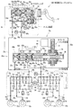
以上説明したように、第1実施形態に係る車両用ブレーキシステム10Aは、図3に示すように、入力装置14とモータシリンダ装置(電動ブレーキアクチュエータ)16とVSA装置(車両挙動安定化装置)18とを、エンジンルーム(動力装置の搭載室)R内において互いに分離して(別体にて)構成して配置したので、入力装置14、モータシリンダ装置16、VSA装置18のそれぞれのサイズを小型化することができ、レイアウトの自由度を高めることができる。
なお、図3中、符号12は、ブレーキペダルであり、符号20a1、20a2、20b1、20b2は、それぞれ入力装置14の接続ポートであり、符号22b、22c、22e、22fは、それぞれ配管チューブであり、符号24a、24bは、それぞれモータシリンダ装置16の出力ポートであり、符号26a、26bは、それぞれVSA装置18の導入ポートであり、符号34は、入力装置14のマスタシリンダであり、符号36は、マスタシリンダ14の第1リザーバであり、符号64は、ストロークシミュレータであり、符号72は、モータシリンダ装置16の電動モータであり、符号84は、モータシリンダ装置16の第2リザーバであり、符号303は、入力装置14のスタッドボルトである。
As described above, the vehicle brake system 10A according to the first embodiment includes the input device 14, the motor cylinder device (electric brake actuator) 16, and the VSA device (vehicle behavior stabilization device) 18, as shown in FIG. Are arranged separately (separately) from each other in the engine room (power device mounting chamber) R, and the sizes of the input device 14, the
In FIG. 3,
ところで、エンジンルームR内には、動力装置の他に、電気系、吸気系、排気系、冷却系などの構造物が搭載されるため、必然的に大きな空スペース(設置スペース)を確保することが難しくなる。そこで、本実施形態のように、入力装置14、モータシリンダ装置16及びVSA装置18をそれぞれ分離して構成することで、個々の装置(入力装置14、モータシリンダ装置16、VSA装置18)のサイズをそれぞれ小さく構成することができ、大きな空スペースを確保する必要がなる。これにより、エンジンルームR内の狭い空スペースであっても前記各装置を搭載することが可能になり、レイアウトが容易になる。
By the way, in the engine room R, in addition to the power unit, structures such as an electric system, an intake system, an exhaust system, and a cooling system are mounted, so a large empty space (installation space) must be secured. Becomes difficult. Therefore, as in the present embodiment, the input device 14, the
また、第1実施形態によれば、入力装置14とモータシリンダ装置16とVSA装置18とをそれぞれ分離して構成することで、各装置(入力装置14、モータシリンダ装置16、VSA装置18)の汎用性を向上して異なる車種に適用し易くなる。
According to the first embodiment, the input device 14, the
また、第1実施形態によれば、モータシリンダ装置16を入力装置14から離間して配置することにより、音や振動の発生源となるモータシリンダ装置16を運転者から離して配置することが可能になるため、運転者に音や振動による違和感(不快感)を与えるのを防止できる。
Further, according to the first embodiment, the
また、第1実施形態によれば、エンジンルームR内においては車幅方向の右側又は左側に偏って空スペースが形成されることは少ないので、モータシリンダ装置16とVSA装置18を車幅方向において互いに逆側に配置することで、これらモータシリンダ装置16とVSA装置18を設置するための空スペースが確保し易くなり、レイアウトが容易になる。
Further, according to the first embodiment, in the engine room R, the empty space is less likely to be formed on the right side or the left side in the vehicle width direction. Therefore, the
また、一体型の従来の電動倍力装置(例えば、特許文献1参照)とVSA装置との接続では一対一の関係でそれらの接続態様は一義的に決まってしまうところ、これに対して、第1実施形態によれば、入力装置14とモータシリンダ装置16とVSA装置18とをそれぞれ分離して構成するので、これらを配管チューブで接続する際に、その接続態様にバリエーションを持たせることができる。したがって、第1実施形態によれば、車両V(図1参照)に対する搭載性に優れる車両用ブレーキシステム10Aを提供することができる。
In addition, in the connection between the integrated conventional electric booster (see, for example, Patent Document 1) and the VSA device, the connection mode is uniquely determined in a one-to-one relationship. According to one embodiment, since the input device 14, the
また、第1実施形態によれば、入力装置14の接続ポート20a、20bを、VSA装置18と、モータシリンダ装置16とのそれぞれに、独立の各配管チューブ22b、22c、22f、22eにより接続する。そのため、前記したように、例えば、各車種の空スペース(設置スペース)に応じて、VSA装置18と、モータシリンダ装置16とを分離して配置した場合であっても、配管設計をシンプルに行うことができる。また、独立の配管チューブ22b、22c、22f、22eで構成されているので、配管取替時に配管チューブ22b、22c、22f、22eの交換を個別に行うことができる。
Further, according to the first embodiment, the
(第2実施形態)
次に、本発明の第2実施形態に係る車両用ブレーキシステムについて説明する。なお、以下の説明では、前記第1実施形態と同じ構成要素については、同じ符号を付してその詳細な説明を省略する。
また、前記第1実施形態では、図3に示すように、入力装置16の各接続ポート20a1、20a2、20b1、20b2を、VSA装置18の各導入ポート26a、26bと、モータシリンダ装置16の各出力ポート24a、24bとのそれぞれに、独立の各配管チューブ22b、22c、22f、22eにより接続しているのに対して、第2実施形態に係る車両用ブレーキシステム10B(図4参照)は、図5に示すように、入力装置16の各接続ポート20a、20bを、VSA装置18の各導入ポート26a、26bと、モータシリンダ装置16の各出力ポート24a、24bとを接続する配管チューブ22b、22c、及び配管チューブ22e、22fに対して、ジョイント(分岐管)23a、23bにより接続した点で相違する。
したがって、以下では、その相違点について主に説明し、共通点についての詳細な説明は省略する。次に参照する図4は、本発明の第2実施形態に係る車両用ブレーキシステムの概略構成図、図5は、本発明の第2実施形態に係る車両用ブレーキシステムにおいて、入力装置に対して車両挙動安定化装置及び電動ブレーキアクチュエータを配管チューブで接続した一態様を示す斜視図である。
(Second Embodiment)
Next, a vehicle brake system according to a second embodiment of the present invention will be described. In the following description, the same components as those in the first embodiment are denoted by the same reference numerals, and detailed description thereof is omitted.
In the first embodiment, as shown in FIG. 3, the
Therefore, in the following, the difference will be mainly described, and a detailed description of the common points will be omitted. Next, FIG. 4 to be referred to is a schematic configuration diagram of the vehicle brake system according to the second embodiment of the present invention, and FIG. 5 is a block diagram of the vehicle brake system according to the second embodiment of the present invention. It is a perspective view which shows the aspect which connected the vehicle behavior stabilization apparatus and the electric brake actuator with the piping tube.
図4に示すように、第2実施形態に係る車両用ブレーキシステム10Bの入力装置14は、第1実施形態に係る車両用ブレーキシステム10Aの入力装置14(図2参照)と異なって、入力装置14内に連結点A1、A2(図2参照)を有していない。
したがって、図4に示すように、第2実施形態の入力装置14においては、マスタシリンダ34の出力ポート54aと接続される第1液圧路58aの末端に形成される接続ポート20aと、マスタシリンダ34の出力ポート54bと接続される第2液圧路58bの末端に形成される接続ポート20bとの2つのポートが設けられている。
As shown in FIG. 4, the input device 14 of the vehicle brake system 10B according to the second embodiment is different from the input device 14 (see FIG. 2) of the vehicle brake system 10A according to the first embodiment. 14 does not have connection points A1 and A2 (see FIG. 2).
Therefore, as shown in FIG. 4, in the input device 14 of the second embodiment, the
そして、入力装置14とVSA装置18とは、第1液圧系統70aとしての、配管チューブ22a、連結点A1としてのジョイント(三方の分岐管)23a、及び配管チューブ22cを介して互いに接続され、第2液圧系統70bとしての、配管チューブ22d、連結点A2としてのジョイント(三方の分岐管)23b、及び配管チューブ22fを介して互いに接続されている。
The input device 14 and the
また、モータシリンダ装置16は、第1液圧系統70aとしての配管チューブ22bを介してジョイント23aと接続され、第2液圧系統70bとしての配管チューブ22eを介してジョイント23bと接続されている。
The
つまり、ジョイント23aを基準として、入力装置14の接続ポート20aとジョイント23aとが配管チューブ22aによって接続され、また、モータシリンダ装置16の出力ポート24aとジョイント23aとが配管チューブ22bによって接続され、さらに、VSA装置18の導入ポート26aとジョイント23aとが配管チューブ22cによって接続されている、
That is, with reference to the joint 23a, the
また、ジョイント23bを基準として、入力装置14の接続ポート20bとジョイント23bとが配管チューブ22dによって接続され、また、モータシリンダ装置16の出力ポート24bとジョイント23bとが配管チューブ22eによって接続され、さらに、VSA装置18の導入ポート26bとジョイント23bとが配管チューブ22fによって接続されている。
With reference to the joint 23b, the
換言すると、図4に示すマスタシリンダ34の出力ポート54aと第1液圧路58aを介して繋がる入力装置14の接続ポート20aは、図5に示すように、VSA装置18の導入ポート26aと、モータシリンダ装置16の出力ポート24aとを接続する配管チューブ22c及び配管チューブ22bに対して、ジョイント23a及び配管チューブ22aを介して接続される。
In other words, the
また、図4に示すマスタシリンダ34の出力ポート54bと第2液圧路58bを介して繋がる入力装置14の接続ポート20bは、図5に示すように、VSA装置18の導入ポート26bと、モータシリンダ装置16の出力ポート24bとを接続する配管チューブ22f及び配管チューブ22eに対して、ジョイント23b及び配管チューブ22dを介して接続される。
Further, as shown in FIG. 5, the
そして、以上の相違点を除けば、本実施形態に係る車両用ブレーキシステム10Bと、前記第1実施形態に係る車両用ブレーキシステム10A(図2及び図3参照)と同様の構成とすることができる。 Except for the above differences, the vehicle brake system 10B according to the present embodiment and the vehicle brake system 10A according to the first embodiment (see FIGS. 2 and 3) may have the same configuration. it can.
本実施形態に係る車両用ブレーキシステム10Bは、基本的に以上のように構成されるものであり、この車両用ブレーキシステム10Bによれば、前記第1実施形態に係る車両用ブレーキシステム10Aと同様の作用効果を奏すると共に、更に次の作用効果をも奏することができる。 The vehicle brake system 10B according to the present embodiment is basically configured as described above. According to the vehicle brake system 10B, the same as the vehicle brake system 10A according to the first embodiment. In addition to the effects described above, the following effects can also be achieved.
本実施形態に係る車両用ブレーキシステム10Bは、図5に示すように、入力装置16の各接続ポート20a、20bを、VSA装置18の各導入ポート26a、26bと、モータシリンダ装置16の各出力ポート24a、24bとを接続する配管チューブ22b、22c、及び配管チューブ22e、22fに対して、ジョイント(分岐管)23a、23bにより接続している。したがって、この車両用ブレーキシステム10Bによれば、前記第1実施形態に係る車両用ブレーキシステム10Aの入力装置14における接続ポートの数が4つ(図3の接続ポート20a1、20a2、20b1、20b2)に対して、2つ(図5の接続ポート20a、20b)に減じることができる。その結果、入力装置14に接続される配管チューブの数を4つ(図3の配管チューブ22b、22c、22e、22f)から2つ(図5の配管チューブ22a、22d)に減じることができる。
As shown in FIG. 5, the vehicle brake system 10 </ b> B according to this embodiment includes the
また、エンジンルームR内で、入力装置16からVSA装置18及びモータシリンダ装置16を離間して配置すると共に、VSA装置18とモータシリンダ装置16とを近接させて配置した際に、VSA装置18とモータシリンダ装置16とを接続する配管チューブ(図5の配管チューブ22b、22c、22e、22f)を短くすると共に、入力装置14とジョイント23a、23bとを接続する配管チューブ(図5の配管チューブ22a、22d)を長くすることによって、使用する配管チューブ全体の長さを低減することができる。
Further, in the engine room R, when the
また、入力装置14に接続される配管チューブの数を4つ(図3の配管チューブ22b、22c、22e、22f)から2つ(図5の配管チューブ22a、22d)に減じることができることで、これらをエンジンルームR内の適所に固定するための固定具を、より簡素化することができると共に、固定具の配置数をも減じることができる。
Further, the number of piping tubes connected to the input device 14 can be reduced from four (
以上、本発明の実施形態について説明したが、本発明は前記実施形態に限定されず、種々の形態で実施することができる。
前記第1実施形態及び第2実施形態においては、モータシリンダ装置16の位置は、フロントサイドフレーム1aの後側に限定されるものではなく、前側であってもよく、またフロントサイドフレーム1aの内側面に限定されるものではなく、フロントサイドフレーム1aの上面側などであってもよい。また、モータシリンダ装置16は、ダッシュボード2の車幅方向の左側、ダンパハウジング1fの側面などに取り付けるようにしてもよい。
As mentioned above, although embodiment of this invention was described, this invention is not limited to the said embodiment, It can implement with a various form.
In the first embodiment and the second embodiment, the position of the
また、第1実施形態においては、入力装置14における接続ポートの数を4つ(図3の接続ポート20a1、20a2、20b1、20b2)とし、モータシリンダ装置16の出力ポートの数を2つ(図3の出力ポート24a、24b)とし、VSA装置18の導入ポートの数を2つ(図3の導入ポート26a、26b)としたが、これらは増減することができる。また、第2実施形態においても入力装置14における接続ポート20a、20b、モータシリンダ装置16の出力ポート24a、24b、及びVSA装置18の導入ポート26a、26bの数を増減することができる。
In the first embodiment, the number of connection ports in the input device 14 is four (connection ports 20a1, 20a2, 20b1, and 20b2 in FIG. 3), and the number of output ports in the
また、本発明は、右ハンドル車及び左ハンドル車のいずれにおいても適用できることは言うまでもない。 Needless to say, the present invention can be applied to both right-hand drive vehicles and left-hand drive vehicles.
10A 車両用ブレーキシステム
10B 車両用ブレーキシステム
12 ブレーキペダル
14 入力装置
16 モータシリンダ装置(電動ブレーキアクチュエータ)
18 VSA装置(車両挙動安定化装置)
20a 接続ポート
20b 接続ポート
22a 配管チューブ
22b 配管チューブ
22c 配管チューブ
22d 配管チューブ
22e 配管チューブ
22f 配管チューブ
23a ジョイント(分岐管)
23b ジョイント(分岐管)
24a 出力ポート
24b 出力ポート
26a 導入ポート
26b 導入ポート
34 マスタシリンダ
54a 出力ポート
54b 出力ポート
58a 第1液圧路
58b 第2液圧路
58c 分岐液圧路
60a 第1遮断弁
60b 第2遮断弁
62 第3遮断弁
64 ストロークシミュレータ
65 液圧室
70a 第1液圧系統
70b 第2液圧系統
72 電動モータ
84 第2リザーバ
Pm 圧力センサ
Pp 圧力センサ
DESCRIPTION OF SYMBOLS 10A Vehicle brake system 10B
18 VSA device (vehicle behavior stabilization device)
23b Joint (branch pipe)
Claims (1)
少なくとも前記ブレーキ操作に応じた電気信号に基づいてブレーキ液圧を発生する電動ブレーキアクチュエータと、
前記電動ブレーキアクチュエータで発生した前記ブレーキ液圧に基づいて車両の挙動の安定化を支援する車両挙動安定化装置と、
を備え、
前記入力装置、前記電動ブレーキアクチュエータ及び前記車両挙動安定化装置は、ダッシュボードの前方において区画された動力装置の搭載室に、互いに分離して配置され、
前記入力装置、前記電動ブレーキアクチュエータ及び前記車両挙動安定化装置は、ブレーキ液を輸送する配管で接続されている車両用ブレーキシステムであって、
前記入力装置は、前記電動ブレーキアクチュエータの異常時にホイールシリンダに液圧を発生可能なマスタシリンダを備え、
前記マスタシリンダの出力ポートを、前記車両挙動安定化装置と、前記電動ブレーキアクチュエータとのそれぞれに、独立の配管により接続したことを特徴とする車両用ブレーキシステム。 An input device for inputting an operator's brake operation;
An electric brake actuator that generates a brake fluid pressure based on at least an electric signal corresponding to the brake operation;
A vehicle behavior stabilization device that supports stabilization of vehicle behavior based on the brake fluid pressure generated by the electric brake actuator;
With
The input device, the electric brake actuator, and the vehicle behavior stabilization device are arranged separately from each other in a power equipment mounting chamber partitioned in front of the dashboard,
The input device, the electric brake actuator, and the vehicle behavior stabilization device are vehicle brake systems connected by piping for transporting brake fluid,
The input device includes a master cylinder capable of generating hydraulic pressure in a wheel cylinder when the electric brake actuator is abnormal.
The vehicular brake system, wherein an output port of the master cylinder is connected to each of the vehicle behavior stabilization device and the electric brake actuator by independent piping.
Priority Applications (5)
| Application Number | Priority Date | Filing Date | Title |
|---|---|---|---|
| JP2010257344A JP5432880B2 (en) | 2010-11-17 | 2010-11-17 | Brake system for vehicles |
| EP11841242.8A EP2641797B1 (en) | 2010-11-17 | 2011-11-11 | Vehicle brake system |
| CN201180055252.9A CN103221285B (en) | 2010-11-17 | 2011-11-11 | Vehicle brake system |
| PCT/JP2011/076055 WO2012067032A1 (en) | 2010-11-17 | 2011-11-11 | Vehicle brake system |
| US13/885,235 US8812210B2 (en) | 2010-11-17 | 2011-11-11 | Vehicle brake system |
Applications Claiming Priority (1)
| Application Number | Priority Date | Filing Date | Title |
|---|---|---|---|
| JP2010257344A JP5432880B2 (en) | 2010-11-17 | 2010-11-17 | Brake system for vehicles |
Publications (2)
| Publication Number | Publication Date |
|---|---|
| JP2012106637A JP2012106637A (en) | 2012-06-07 |
| JP5432880B2 true JP5432880B2 (en) | 2014-03-05 |
Family
ID=46492764
Family Applications (1)
| Application Number | Title | Priority Date | Filing Date |
|---|---|---|---|
| JP2010257344A Active JP5432880B2 (en) | 2010-11-17 | 2010-11-17 | Brake system for vehicles |
Country Status (1)
| Country | Link |
|---|---|
| JP (1) | JP5432880B2 (en) |
Cited By (1)
| Publication number | Priority date | Publication date | Assignee | Title |
|---|---|---|---|---|
| US11565676B2 (en) | 2018-05-30 | 2023-01-31 | Hl Mando Corporation | Electric brake system |
Families Citing this family (4)
| Publication number | Priority date | Publication date | Assignee | Title |
|---|---|---|---|---|
| JP5892706B2 (en) | 2013-12-27 | 2016-03-23 | 日信工業株式会社 | Brake fluid pressure generator |
| US10106138B2 (en) | 2015-02-13 | 2018-10-23 | Autoliv Nissin Brake Systems Japan Co., Ltd. | Brake system |
| JP6304633B2 (en) * | 2015-02-13 | 2018-04-04 | オートリブ日信ブレーキシステムジャパン株式会社 | Brake system |
| JP6512695B2 (en) * | 2015-03-30 | 2019-05-15 | ヴィオニア日信ブレーキシステムジャパン株式会社 | Brake system |
Family Cites Families (4)
| Publication number | Priority date | Publication date | Assignee | Title |
|---|---|---|---|---|
| JPH06183330A (en) * | 1992-12-17 | 1994-07-05 | Nippon Seiko Kk | Motor-driven assist type braking device |
| JP3391324B2 (en) * | 1999-12-27 | 2003-03-31 | トヨタ自動車株式会社 | Brake fluid pressure control device |
| JP2006103548A (en) * | 2004-10-06 | 2006-04-20 | Toyota Motor Corp | Hydraulic brake control device |
| JP4717721B2 (en) * | 2006-06-06 | 2011-07-06 | 本田技研工業株式会社 | Brake device |
-
2010
- 2010-11-17 JP JP2010257344A patent/JP5432880B2/en active Active
Cited By (2)
| Publication number | Priority date | Publication date | Assignee | Title |
|---|---|---|---|---|
| US11565676B2 (en) | 2018-05-30 | 2023-01-31 | Hl Mando Corporation | Electric brake system |
| US11945421B2 (en) | 2018-05-30 | 2024-04-02 | Hl Mando Corporation | Electric brake system |
Also Published As
| Publication number | Publication date |
|---|---|
| JP2012106637A (en) | 2012-06-07 |
Similar Documents
| Publication | Publication Date | Title |
|---|---|---|
| JP5688097B2 (en) | Brake system for vehicles | |
| JP5379113B2 (en) | Input device for vehicle brake system | |
| WO2012067004A1 (en) | Vehicle brake system | |
| WO2012067032A1 (en) | Vehicle brake system | |
| JP5698258B2 (en) | Brake system for vehicles | |
| JP5432880B2 (en) | Brake system for vehicles | |
| JP5840142B2 (en) | Brake system for vehicles | |
| JP5200092B2 (en) | Brake system for vehicle and input device thereof | |
| JP5337133B2 (en) | Brake system for vehicles | |
| JP5149953B2 (en) | Input device for vehicle brake system | |
| JP5364077B2 (en) | Input device for vehicle brake system | |
| JP5646965B2 (en) | Arrangement structure of vehicle structure mounting room | |
| JP2012106648A (en) | Vehicle brake system | |
| JP5715382B2 (en) | Brake system for vehicles | |
| JP5364076B2 (en) | Input device for vehicle brake system | |
| JP5537391B2 (en) | Brake system for vehicle and input device thereof | |
| JP5602596B2 (en) | Brake system for vehicles | |
| JP6317659B2 (en) | Brake system for vehicles | |
| JP5276646B2 (en) | Input device for vehicle brake system | |
| JP5427197B2 (en) | Braking force generator for vehicle | |
| JP5193268B2 (en) | Electric brake actuator mounting structure | |
| JP5193269B2 (en) | Electric brake actuator displacement suppression structure | |
| JP5297439B2 (en) | Piping support structure for electric brake actuator |
Legal Events
| Date | Code | Title | Description |
|---|---|---|---|
| A621 | Written request for application examination |
Free format text: JAPANESE INTERMEDIATE CODE: A621 Effective date: 20121128 |
|
| A131 | Notification of reasons for refusal |
Free format text: JAPANESE INTERMEDIATE CODE: A131 Effective date: 20130903 |
|
| A521 | Written amendment |
Free format text: JAPANESE INTERMEDIATE CODE: A523 Effective date: 20131101 |
|
| TRDD | Decision of grant or rejection written | ||
| A01 | Written decision to grant a patent or to grant a registration (utility model) |
Free format text: JAPANESE INTERMEDIATE CODE: A01 Effective date: 20131126 |
|
| A61 | First payment of annual fees (during grant procedure) |
Free format text: JAPANESE INTERMEDIATE CODE: A61 Effective date: 20131206 |
|
| R150 | Certificate of patent or registration of utility model |
Free format text: JAPANESE INTERMEDIATE CODE: R150 Ref document number: 5432880 Country of ref document: JP Free format text: JAPANESE INTERMEDIATE CODE: R150 |
|
| R250 | Receipt of annual fees |
Free format text: JAPANESE INTERMEDIATE CODE: R250 |