JP5432273B2 - Collet for use with valves - Google Patents
Collet for use with valves Download PDFInfo
- Publication number
- JP5432273B2 JP5432273B2 JP2011534562A JP2011534562A JP5432273B2 JP 5432273 B2 JP5432273 B2 JP 5432273B2 JP 2011534562 A JP2011534562 A JP 2011534562A JP 2011534562 A JP2011534562 A JP 2011534562A JP 5432273 B2 JP5432273 B2 JP 5432273B2
- Authority
- JP
- Japan
- Prior art keywords
- opening
- collet
- shaft
- rectangular
- center
- Prior art date
- Legal status (The legal status is an assumption and is not a legal conclusion. Google has not performed a legal analysis and makes no representation as to the accuracy of the status listed.)
- Expired - Fee Related
Links
Images


Classifications
-
- F—MECHANICAL ENGINEERING; LIGHTING; HEATING; WEAPONS; BLASTING
- F16—ENGINEERING ELEMENTS AND UNITS; GENERAL MEASURES FOR PRODUCING AND MAINTAINING EFFECTIVE FUNCTIONING OF MACHINES OR INSTALLATIONS; THERMAL INSULATION IN GENERAL
- F16K—VALVES; TAPS; COCKS; ACTUATING-FLOATS; DEVICES FOR VENTING OR AERATING
- F16K31/00—Actuating devices; Operating means; Releasing devices
- F16K31/12—Actuating devices; Operating means; Releasing devices actuated by fluid
- F16K31/16—Actuating devices; Operating means; Releasing devices actuated by fluid with a mechanism, other than pulling-or pushing-rod, between fluid motor and closure member
- F16K31/165—Actuating devices; Operating means; Releasing devices actuated by fluid with a mechanism, other than pulling-or pushing-rod, between fluid motor and closure member the fluid acting on a diaphragm
- F16K31/1655—Actuating devices; Operating means; Releasing devices actuated by fluid with a mechanism, other than pulling-or pushing-rod, between fluid motor and closure member the fluid acting on a diaphragm for rotating valves
-
- F—MECHANICAL ENGINEERING; LIGHTING; HEATING; WEAPONS; BLASTING
- F16—ENGINEERING ELEMENTS AND UNITS; GENERAL MEASURES FOR PRODUCING AND MAINTAINING EFFECTIVE FUNCTIONING OF MACHINES OR INSTALLATIONS; THERMAL INSULATION IN GENERAL
- F16K—VALVES; TAPS; COCKS; ACTUATING-FLOATS; DEVICES FOR VENTING OR AERATING
- F16K31/00—Actuating devices; Operating means; Releasing devices
- F16K31/12—Actuating devices; Operating means; Releasing devices actuated by fluid
- F16K31/16—Actuating devices; Operating means; Releasing devices actuated by fluid with a mechanism, other than pulling-or pushing-rod, between fluid motor and closure member
- F16K31/163—Actuating devices; Operating means; Releasing devices actuated by fluid with a mechanism, other than pulling-or pushing-rod, between fluid motor and closure member the fluid acting on a piston
- F16K31/1635—Actuating devices; Operating means; Releasing devices actuated by fluid with a mechanism, other than pulling-or pushing-rod, between fluid motor and closure member the fluid acting on a piston for rotating valves
-
- Y—GENERAL TAGGING OF NEW TECHNOLOGICAL DEVELOPMENTS; GENERAL TAGGING OF CROSS-SECTIONAL TECHNOLOGIES SPANNING OVER SEVERAL SECTIONS OF THE IPC; TECHNICAL SUBJECTS COVERED BY FORMER USPC CROSS-REFERENCE ART COLLECTIONS [XRACs] AND DIGESTS
- Y10—TECHNICAL SUBJECTS COVERED BY FORMER USPC
- Y10T—TECHNICAL SUBJECTS COVERED BY FORMER US CLASSIFICATION
- Y10T403/00—Joints and connections
- Y10T403/70—Interfitted members
- Y10T403/7047—Radially interposed shim or bushing
- Y10T403/7051—Wedging or camming
- Y10T403/7052—Engaged by axial movement
- Y10T403/7058—Split or slotted bushing
Landscapes
- Engineering & Computer Science (AREA)
- General Engineering & Computer Science (AREA)
- Mechanical Engineering (AREA)
- Mechanically-Actuated Valves (AREA)
- Lift Valve (AREA)
Description
本開示は、概括的には、制御弁に関し、より具体的には、弁と共に使用するコレットに関する。 The present disclosure relates generally to control valves, and more specifically to collets for use with valves.
流体処理システムでは、標準的には、プロセス流体の流れを制御するために例えば回転弁のような弁を使用している。一般的には、回転弁は、標準的には、流体経路に配置され、シャフトを介して回転弁の本体と回転自在に連結された流体流れ制御部材を含んでいる。標準的には、回転弁から延在するシャフトの一部分は、流れ制御部材を作動させるアクチュエータ(例えば空気圧式アクチュエータ、電動アクチュエータ、油圧式アクチュエータ等)と作動可能に連結されている。アクチュエータを弁棒と連結させるために、レバー又はレバーアームが、標準的には、採用されている。レバーは、アクチュエータの心棒の線形変位を弁棒の回転変位に変換する。このようにして、レバーの回転は、弁を通過する流体の流れを増やす又は制限するために弁棒及び流れ制御部材(例えば円板、ボール等)を回転させる。作動時、レバー及び弁棒を回転させ、それによって弁の流れ制御部材を、回転弁を通過する所望の流体流れを達成するような所望の角度位置に回転させるようにアクチュエータの変位を制御するために、制御要素を使用する場合がある。 In fluid processing systems, valves such as rotary valves are typically used to control the flow of process fluid. In general, a rotary valve typically includes a fluid flow control member disposed in a fluid path and rotatably connected to a main body of the rotary valve via a shaft. Typically, a portion of the shaft extending from the rotary valve is operably connected to an actuator (eg, pneumatic actuator, electric actuator, hydraulic actuator, etc.) that operates the flow control member. In order to connect the actuator with the valve stem, a lever or lever arm is typically employed. The lever converts the linear displacement of the actuator stem to the rotational displacement of the valve stem. In this way, rotation of the lever rotates the valve stem and flow control member (eg, disc, ball, etc.) to increase or limit the flow of fluid through the valve. In operation, to control the displacement of the actuator to rotate the lever and valve stem, thereby rotating the valve flow control member to the desired angular position to achieve the desired fluid flow through the rotary valve. In some cases, a control element is used.
しかしながら、例えば線形並進を弁棒の回転運動へ変換するレバーのようなシャフト継手は、しばしばバックラッシを起こす傾向がある。レバーがシャフトに対して適切な大きさではない場合に発生する、バックラッシは、レバー接触面とシャフトの接触面との間の遊隙に起因する。バックラッシは、作動の不完全及び弁を通過する流体流れ制御の精度低下をもたらす。更に、工業規格(例えば国際標準化機構)は、アクチュエータが異なった大きさの弁棒と連結するように要求する場合がある。ISO規格を順守するためには、複数の又は異なる製造業者によって作られたアクチュエータ及び弁が、アクチュエータ又は弁の修正を必要とせずに交換可能なように互いに連結することができることが求められる。不正確な大きさの継手に起因するバックラッシを実質的に減らし、制御弁の様々なアクチュエータとの互換性を助長するために、多くの市販されるアクチュエータは、例えば弁棒を受けるためにコレットを備えて適合されたレバーのようなシャフト継手を有している。具体的には、多くの既製品のアクチュエータは、異なった大きさの四角い弁棒を受け入れるために四角い孔又は開口部を有するコレットを提供している。 However, shaft joints, such as levers that convert linear translation into valve stem rotational motion, for example, often tend to cause backlash. The backlash that occurs when the lever is not properly sized relative to the shaft is due to play between the lever contact surface and the shaft contact surface. Backlash results in incomplete operation and reduced accuracy of fluid flow control through the valve. In addition, industry standards (eg, International Organization for Standardization) may require actuators to be coupled with different sized valve stems. In order to comply with ISO standards, it is required that actuators and valves made by multiple or different manufacturers can be connected to each other so that they can be replaced without requiring modification of the actuators or valves. In order to substantially reduce backlash due to inaccurately sized joints and to facilitate compatibility with various actuators in the control valve, many commercially available actuators, for example, require a collet to receive the valve stem. It has a shaft coupling like a lever fitted and fitted. Specifically, many off-the-shelf actuators provide collets with square holes or openings to accept different sized square valve stems.
レバーと四角い弁棒の間で動作損失(lost motion)が生じることを回避するために、コレットは、弁棒の四角い端部に十分な締め付け力を提供する必要がある。コレット及び弁棒間に十分な締め付け力を提供することができない場合、概して、機械的な結合を緩ませ、それによってレバーと弁棒との間の動作損失をもたらす。そのような動作損失は、流れ制御部材の不正確な位置調整、ひいては弁を通過して流れる流体全体の制御不良を招く可能性がある。 In order to avoid lost motion between the lever and the square valve stem, the collet needs to provide sufficient clamping force at the square end of the valve stem. If a sufficient clamping force cannot be provided between the collet and the valve stem, it will generally loosen the mechanical coupling, thereby resulting in a loss of motion between the lever and the valve stem. Such operational losses can lead to inaccurate positioning of the flow control member, and thus poor control of the overall fluid flowing through the valve.
1つの実施例では、回転弁と共に使用するためのシャフト継手アッセンブリは、第1の端部及び第2の端部を有する細長い部材を含んでおり、第1の端部は、長方形のシャフトを受け入れるように構成された第1の開口部を有する継手部を含んでいる。継手部は、弓状の外部表面及び第1の開口部の少なくとも一部を画定している第2の内部表面に隣接する第1の内部表面を有する、少なくとも1つの可撓性部材を含んでいる。第1の内部表面の少なくとも一部は、長方形シャフトの第1の側面と係合するものであり、第2の内部表面の少なくとも一部は、長方形シャフトの第2の側面と係合するものである。シャフト継手アッセンブリは、細長い部材を受け入れる第2の開口部及び継手部を受け入れるように構成されたテーパ付きの第3の開口部を有するスリーブを更に含んでいる。 In one embodiment, a shaft coupling assembly for use with a rotary valve includes an elongated member having a first end and a second end, the first end receiving a rectangular shaft. A joint portion having a first opening configured as described above is included. The joint includes at least one flexible member having a first inner surface adjacent to an arcuate outer surface and a second inner surface defining at least a portion of the first opening. Yes. At least a portion of the first inner surface is engaged with the first side of the rectangular shaft and at least a portion of the second inner surface is engaged with the second side of the rectangular shaft. is there. The shaft coupling assembly further includes a sleeve having a second opening for receiving the elongated member and a tapered third opening configured to receive the coupling.
別の実施例では、長方形シャフトと共に使用されるコレットは、細長い部材と連結されるように構成され、長方形のシャフトを受け入れるために実質的に長方形の孔を有している複数の可撓性部材を含んでいる。可撓性部材は、長方形の孔の少なくとも一部を画定している座表面及びレバー開口部の内部表面と係合する弓状の外部表面を有している。複数の可撓性部材の第1の可撓性部材の少なくとも1つの座表面は、長方形シャフトの第1の側面及び第2の側面を受け入れるものである。 In another embodiment, a collet used with a rectangular shaft is configured to be coupled with an elongate member and a plurality of flexible members having substantially rectangular holes for receiving the rectangular shaft. Is included. The flexible member has a seating surface that defines at least a portion of the rectangular hole and an arcuate outer surface that engages the inner surface of the lever opening. At least one seating surface of the first flexible member of the plurality of flexible members is to receive a first side and a second side of the rectangular shaft.
更に別の実施例では、コレットは、細長い部材と連結され、丸みを帯びた角及び長方形シャフトを受け入れるように構成された第1の開口部を有する長方形断面形状を画定している外部表面を有している継手部を含んでいる。継手部は、複数の可撓性部材を備えており、それぞれは、第1の開口部の少なくとも一部を画定している第2の内部表面に隣接する第1の内部表面と、継手部の丸みを帯びた角の少なくとも一部を画定している弓状の外部表面と、を有している。 In yet another embodiment, the collet has an exterior surface that defines a rectangular cross-sectional shape coupled to the elongated member and having a rounded corner and a first opening configured to receive a rectangular shaft. The joint part is included. The joint includes a plurality of flexible members, each having a first inner surface adjacent to a second inner surface defining at least a portion of the first opening, and the joint portion. And an arcuate outer surface defining at least a portion of rounded corners.
本明細書で開示される例示的なコレットは、弁アクチュエータを制御するために異なる大きさの、略正方形又は長方形の弁棒と連結するために使用され得る。本明細書で使用する場合、略長方形という用語は、略正方形の形状を含んでいる。公知の結合技法とは対照的に、本明細書で説明している例示的なコレットは、楔、シャフトキー等の使用を必要とせずにレバーと実質的な長方形(例えば正方形)シャフトとの間の実質的に密着した継手を提供するように構成されている。作動時、本明細書で説明している例示的なコレットは、アクチュエータと閉鎖部材(例えば弁体)との間の作動の不完全を実質的になくす。更に、本明細書で説明している例示的なコレットは、例えば取り付け工程、修理工程などを目的としたアクチュエータ及び弁棒の連結及び分離を容易にすることができる。 The exemplary collets disclosed herein can be used to connect with different sized, generally square or rectangular valve stems to control valve actuators. As used herein, the term substantially rectangular includes a substantially square shape. In contrast to known coupling techniques, the exemplary collet described herein does not require the use of wedges, shaft keys, etc., between the lever and the substantially rectangular (eg, square) shaft. Of substantially tight fittings. In operation, the exemplary collet described herein substantially eliminates incomplete actuation between the actuator and the closure member (eg, valve body). Furthermore, the exemplary collets described herein can facilitate the connection and disconnection of actuators and valve stems, eg, for attachment, repair, etc. purposes.
以下にさらに詳細に説明するように、例示的なコレットは、長方形シャフトを受け入れるように構成された略長方形の開口部を有している継手部と連結される細長い部材を含んでいてもよい。具体的には、継手部は、長方形開口部の少なくとも一部を画定している第2の内部表面に隣接する第1の内部表面を有している、少なくとも1つの可撓性部材(例えばタング、指状突起等)を含んでいる。第1の内部表面及び第2の内部表面は、或る角度(例えば270度角度)を形成しており、長方形シャフトの角表面を受け入れる座表面を画定している。可撓性部材は、テーパ付きであり、例えばレバー又はスリーブのような継手構成要素のテーパ付きの内部表面と係合するように構成された弓状又は円筒形状の外部表面を更に含んでいる。1つの実施例では、可撓性部材は、テーパ付きの円筒形状の外部表面及び円形扇形を有している。可撓性部材は、継手構成要素によって細長い部材のシャフト方向にずらすことができる。一般的には、本明細書で説明している例示的なコレットを実装するために任意の数の可撓性部材を使用してもよい。 As described in further detail below, an exemplary collet may include an elongate member that is coupled to a joint having a generally rectangular opening configured to receive a rectangular shaft. Specifically, the joint has at least one flexible member (e.g., a tongue) having a first inner surface adjacent to a second inner surface that defines at least a portion of the rectangular opening. , Finger projections, etc.). The first inner surface and the second inner surface form an angle (eg, a 270 degree angle) and define a seating surface that receives the angular surface of the rectangular shaft. The flexible member is tapered and further includes an arcuate or cylindrical outer surface configured to engage a tapered inner surface of a coupling component, such as a lever or sleeve. In one embodiment, the flexible member has a tapered cylindrical outer surface and a circular sector. The flexible member can be displaced in the shaft direction of the elongate member by the coupling component. In general, any number of flexible members may be used to implement the exemplary collet described herein.
本明細書で説明している例示的なコレットは、有利なことに、可撓性部材が締め付け力を弁棒の正方形端部の角表面に加える又は集中させることを可能にしている。そのような締め付け力をそれらの角表面に加えることは、コレット及びコレットが連結される弁棒の間での実質的に改良された継手又はトルク伝達を可能にする。特に、本明細書で説明している実施例では、弓状の外部表面の中心(即ち曲率中心)は、長方形シャフトのそれぞれの角の内側に位置している。更に、本明細書で説明している例示的な可撓性部材の弓状又は円筒形状のテーパ付きの外部表面は、継手構成要素とコレットとの間の作動の不完全、ひいてはアクチュエータと継手構成要素及びコレットに関連付けられる弁の流れ制御部材との間の作動の不完全をさらに回避する又は最小限に抑えるべく、継手構成要素とコレットとの間に実質的な密着した嵌め合い又は接続を提供するように、継手構成要素(例えばレバー)の内部表面と係合している。 The exemplary collet described herein advantageously allows the flexible member to apply or concentrate a clamping force on the angular surface of the square end of the valve stem. Applying such a clamping force to their angular surfaces allows a substantially improved coupling or torque transmission between the collet and the valve stem to which the collet is connected. In particular, in the embodiment described herein, the center of the arcuate outer surface (ie, the center of curvature) is located inside each corner of the rectangular shaft. Further, the arcuate or cylindrical tapered outer surface of the exemplary flexible member described herein may cause incomplete operation between the coupling component and the collet, and thus the actuator and coupling configuration. Provide a substantially intimate fit or connection between the coupling component and the collet to further avoid or minimize incomplete actuation between the element and the valve flow control member associated with the collet. As such, it engages an internal surface of a coupling component (eg, a lever).
図1Aは、本明細書で説明している例示的な継手アッセンブリ102を有している例示的な回転制御弁アッセンブリ100を図解している。図1Bは、図1Aの回転制御弁アッセンブリ100を実装するために使用することができる回転弁104を図解している。一般的には、例示的な弁アッセンブリ100は、継手アッセンブリ102を介して回転弁104と作動可能なように連結されているアクチュエータ106を含んでいる。アクチュエータ106は、弁104を通過して流れる流体を制御するために回転弁104を開閉するように作動させる(即ち回転させる、向きを変える等)ように構成される。
FIG. 1A illustrates an exemplary rotation
図1Aを参照すると、アクチュエータ106(例えば隔膜アクチュエータ、ピストンアクチュエータ等)は、回転制御弁100のハウジング108と連結されている。ハウジング108は、第1の面板112及び第1の面板112と向かい合っている(即ちアクチュエータ106の背面)第2の面板(図示せず)を含んでいる。第1の面板112及び第2の面板は、実質的には類似している又は同一であり、現場で構成することができる(field configurable)、フェイルセーフのアクチュエータ106の動作を可能にしている。第1の面板112は、回転弁104をアクチュエータ106に取り付けるための複数の取り付け穴114を含んでいる。取り付けブラケット116(図1B)は、締結具118(図1B)又は取り付け穴114の中へ入る及び/又はその中を貫通する任意の他の適切な締結機構を用いて回転弁104を面板112に取り付ける。
Referring to FIG. 1A, an actuator 106 (for example, a diaphragm actuator, a piston actuator, etc.) is connected to the
図1Aで図解しているように、第1の面板112は、継手アッセンブリ102を曝け出すためにアクチュエータ106から取り外されている。継手アッセンブリ102は、例示的なコレット122と連結する又は係合する例示的なレバー120を含む。レバー120及びコレット122のアッセンブリは、以下でさらに詳細に説明される。コレット122は、回転弁104を作動可能にアクチュエータ106と連結させる。アクチュエータ106は、レバー120と連結するロッドエンド軸受124を有するアクチュエータ心棒(図示せず)を含んでいる。
As illustrated in FIG. 1A, the
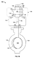
図1Bを参照すると、回転弁104は、流れ制御部材128及び座表面又はシール環130を収納している弁本体126を含んでいる。流れ制御部材128は、弁104を通過する流体の流れを制御するためにシール環130と係合している。流れ制御部材128は、弁棒132と連結されており、さらに、コレット122を介してレバー120と連結されている。弁棒132は、略正方形の端部134を有しており、正方形のシャフトに対するISO規格に適合し得る。しかしながら、弁棒132は、任意の他の形状(例えば任意の多角形形状)及び/又は大きさを用いて実装されてもよい。以下により詳細に説明されるように、コレット122は、コレット122がレバー120と連結される時、締め付け力を回転弁104の弁棒132に加えるように構成されている。
Referring to FIG. 1B, the
図1Bで示しているように、レバー106の第1の端部136は、継手アッセンブリ102を形成するために例示的なコレット122を受け入れる又は当該コレットと係合するように構成されている第1のスリーブ138を提供している。同様に、レバー106の第2の端部140は、第2の継手144を形成するために例示的なコレット122をその中に通して挿入し得る第2のスリーブ142を提供している。第1のスリーブ138又は第2のスリーブ142が例示的なコレット122と係合するように、例示的なコレット122を、レバー120の中へ引き込み得る。以下により詳細に説明するように、レバー120は、座金146と係合し、ファスナ148は、コレット122が締め付け力を弁棒132に加えるようにさせるためにレバー120の内部でコレット122を引き寄せる。
As shown in FIG. 1B, the
作動時、回転制御弁アッセンブリ100は、アクチュエータ106を変位させるように例えば圧縮空気のような制御信号を受信する。アクチュエータ106の変位は、アクチュエータ心棒の対応する線形変位をもたらす。アクチュエータ心棒の線形変位は、レバー120の回転変位に変換され、これによってレバー120は、コレット122を介して回転力を弁棒132へ伝える。例えば、レバー120が回転すると、コレット122は、弁棒132を回転させ、回転弁104を通過して流れている流体を変化させる又は制御するような所望の角度位置まで流れ制御部材128を回転させる。流れ制御部材128が閉じると、流れ制御部材128は、弁104を通過する流体の流れを止めるために、回転弁104を通過する流れ経路を取り囲んでいるシール環130と係合する。
In operation, rotation
流れ制御部材128を調整することは、所望のプロセス流体流れ及び/又は圧力を実現するために、完全に開いた位置と完全に閉じた位置の間で流れ制御部材128の位置を調節及び制御することを含んでいてもよい。更に、流れ制御部材128を調整することは、プロセス流体の流れ及び/又は圧力を継続的に測定するように構成されているフィードバックシステム(図示せず)と接続して実行してもよい。フィードバックシステムは、その後、プロセス流体の流れ及び/又は圧力の変化に応えて、例えばアクチュエータ106がレバー120の少なくともその一部を作動させるようにしてもよい。調整の適用時、レバー120及び弁棒132の間での作動の不完全を最小に抑える又は減らすことは、流れ制御部材128の正確な位置調整を実現するために重要である。そのような作動の不完全は、概して、流れ制御部材の実際の位置を所望の位置からずれさせる。そのような作動の不完全が発生することを実質的に減らす又は阻止することは、より正確な且つ改良された弁性能を提供する。
Adjusting the
図2Aは、図1Aで示している例示的なレバー120及び例示的なコレット122を図解している。図2Bは、図1A及び図2Aの例示的なレバー120及び弁棒132と連結されている例示的なコレット122の端面図を図解している。図2Cは、図1A、図2A及び図2Bの例示的なコレット122の拡大した一部を図解している。図2Dは、図1A、図2A及び図2Bの例示的なコレット122の側面図を図解している。上述のように、組み立てられた構成では、例示的なレバー120及び例示的なコレット122は、例えば図1A及び図1Bで示しているような継手を形成する。
FIG. 2A illustrates the
レバー120は、本体202の中心に実質的に近接している第1の開口部又は孔204を有している本体202を含んでいる。スリーブ138は、開口部204より大きい第2の開口部206を含んでいる。第2の開口部206は、内部表面208を有しており、コレット122を受け入れるために開口部206を構成している丸みを帯びた又は円形状の角210a〜210dを含んでいる長方形又は正方形の断面形状を画定している。更に、内部表面208は、第1の開口部204に向けてテーパ付きになっている。幾つかの実施例では、レバー120の第2のスリーブ142は、更に、第2の開口部206と対向していて、丸みを帯びた又は円形状の角を含んでいる長方形又は正方形の断面形状を有していて、第1の開口部204に向けてテーパ付きになっている第3の開口部(図示せず)を含んでいてもよい。図解している実施例では、スリーブ138及び142は、レバー120と一体化して形成されている。しかしながら、他の実施例では、スリーブ138及び/又は142は、任意の他の単数又は複数の適切な方法でレバー120に受け入れられる又は当該レバーと連結されてもよい。
The
レバー120は、本体202から延在しているレバーアーム212及び214を含んでいる。アーム212及び214は、レバー120をアクチュエータ心棒のロッドエンドベアリング124(図1A)と回転自在に連結するために締結具(図示せず)を受け入れるアパーチャ又は取り付け穴216及び218をそれぞれ含んでいる。更に、本体202は、位置決め装置(図示せず)と作動可能なように連結しているカム(図示せず)を含んでいてもよく、当該位置決め装置はカムの位置に基づいて弁100を制御するためにフィードバックを提供している。
更に図2B及び図2Cを参照すると、コレット122は、第1の端部222及び第2の端部224を有している細長い部材220を含んでいる。第1の端部222は、例えば図1Bの弁棒132のような長方形の弁棒を受け入れるように構成された第1の開口部又は実質的に長方形の孔228を有している継手部226を含んでいる。図解している実施例では、継手部226は、実質的に単一の要素又は構造を形成するために細長い部材220と一体化して構成されている。しかしながら、他の実施例では、継手部226は、任意の適切な単数又は複数の締め付け機構を用いて細長い部材220と連結している。
Still referring to FIGS. 2B and 2C, the
継手部226は、複数の可撓性部材230a〜230dを含んでいる。図解している実施例では、複数の可撓性部材230a〜230dのそれぞれは、円形扇形断面形状を有している又は円筒形状の扇形を形成している。可撓性部材230a〜230dは、第1の平面232(例えば略水平面)及び第2の平面234(例えば略垂直面)に対して及び互いに対して、口が広がっている、斜めに切り落とされている、傾斜している又は角度(例えば角度6度)付きである。可撓性部材230a〜230dは、円形又は弓状形状の外部面236a〜236dを含んでいる。弓状外部表面236a〜236dは、レバー120の内部表面208の丸みを帯びた角210a〜210dと係合するような形状になっている。更に、可撓性部材230a〜230dは、第2の開口部206のテーパ付きの表面208と対合可能に係合するようにテーパ付きになっている。
The joint portion 226 includes a plurality of
可撓性部材230a〜230dは、可撓性部材230a〜230dのそれぞれの座表面242a〜242dを形成又は画定している第2の内部表面240a〜240dに隣接するそれぞれの第1の内部表面238a〜238dを含んでいる。第1及び第2の内部表面238a〜238d及び242a〜242dは、継手部226の長方形の孔228の少なくとも一部を画定している。第1の内部表面238a〜238dは、第2の内部表面240a〜240dに対して凡そ垂直であり、それぞれの角度244a〜244dを形成している。更に、可撓性部材230aの第1の内部表面238aは、可撓性部材230b〜230dの第1の内部表面238b〜238dと略平行であり、可撓性部材230aの第2の内部表面240aは、可撓性部材230b〜230dの第2の内部表面240b〜240dと略平行である。可撓性部材230a〜230dのそれぞれの角度244a〜244dは、可撓性部材230a〜230dの第1の端部246(図2D)で最も大きく(例えば270度)、可撓性部材230a〜230dは、テーパ付きになっているので、可撓性部材230a〜230dの長さLに沿ってテーパ付きになっている(例えば角度が減っている)。
The
座表面242a〜242dは、弁棒132のそれぞれの角部248a〜248dを受け入れている。図解している実施例では、第1の内部表面238a及び238dの少なくとも一部分は、長方形シャフト132の第1の側面又は表面250aと係合しており、第2の内部表面240a及び240bの少なくとも一部分は、長方形シャフト132の第1の表面250aに隣接する長方形シャフト132の第2の側面又は表面250bと係合している。同様に、第1の内部表面238b及び238cの少なくとも一部分は、弁棒132の第3の側面又は表面250cと係合しており、第2の内部表面240c及び240dは、弁棒132の第4の側面又は表面250dと係合している。弓状の外部表面236a〜236dは、有利なことに、弁棒132が孔228によって受け入れられる時に、弁棒132のそれぞれの角248a〜248dの内側又は内部に延在する又は位置している湾曲部252a〜252dの中心を有している。例えば、弓状の外部表面236aの湾曲部252aの中心は、可撓性部材230aの第1及び第2の内部表面238a及び240aが長方形シャフト132の第1及び第2の表面250a及び250bとそれぞれ係合している部分の間の長方形シャフト132の角248aの内部に含まれている。これにより、第1及び第2の内部表面238a〜238d及び240a〜240dがより大きい締め付け力を弁棒132の角248a〜248dに加えることを可能にしており、アクチュエータ106がレバー120を回転させるように作動する時に最も有効的なトルク伝達がコレット122と弁棒132との間に発生する。このように、弓状の外部表面236a〜236dは、弁棒132の角248a〜248dの内側に含まれる湾曲部252a〜252dの中心を有しているという理由で、可撓性部材230a〜230dは、弁棒132と連結される時、より有効的な締め付け力を提供している。
The
幾つかの実施例では、第1の内部表面238a〜238d及び第2の内部表面240a〜240dの間の角度244a〜244dは、可撓性部材230a〜230dの第1の端部246では、例えば268度のように270度より僅かに小さくてもよい。このように、第1及び第2の内部表面238a〜238d及び240a〜240dは、弁棒132の製造公差に適合することができる。更に、より大きい締め付け力を、弁棒132の角248a〜248dの近くに集中させることができる。例えば、図2Cで最も明瞭に示されているように、可撓性部材230bの第1の内部表面238b及び第2の内部表面240bの間の角度244bは、第1の端部246では270度より小さく成り得るので、第1の間隙254が、第1の内部表面238bの第1の部分256と弁棒132の表面250cとの間に生じ、第2の間隙258が、第2の内部表面240bの第1の部分260と弁棒132との間に生じる。このように、コレット122が、弁棒132の角248bの近くに締め付け力を集中させることによってレバー120の内部で引き寄せられるので、間隙254及び258は、可撓性部材230bがより大きい締め付け力又は荷重を弁棒132の角248bに伝達することをできるようにする。
In some embodiments, the
更に、本明細書で説明している例示的なコレット122の構成は、実質的に、コレット122の表面と弁棒132との間の把持係合を緩めさせるフレッチングを減らす又は無くす。弁棒132の表面250a〜250d、並びに第1及び第2の内部表面238a〜238d、及び240a〜240dは、十分に密着した把持力又は締め付け力で把持されない場合、フレッチングを発生させる可能性がある微細な表面凹凸を有している。荷重を受けている2つの材料の間の対合する表面又は接触区域の凹凸が、力(例えば、アクチュエータ106を用いて弁棒132に加えられるトルク)による相対的な動きに曝される時、フレッチングは発生し、対合する表面の凹凸が互いに擦り合わされ、かつ剥げ落とさせ、結果的にコレット122及び弁棒132の間の接続に緩みをもたらす。
Further, the
より大きい締め付け力を与えることは、コレット122がレバー120の中へ密着して引き寄せられる締め付け時の間に微細な局所的な降伏を角248a〜248dの近くのそれらの局所的な接触点又は区域に与えることによって、対合する表面の凹凸が擦り合わされることを回避する。局所的な降伏は、コレット122がドローナット148によってレバー120の中に引き込まれる際、弁棒132と穴228との間、並びに第1及び第2の内部表面238a〜238d及び240a〜240dと弁棒132の表面250a〜250dとの間に、対合する表面の凹凸又は接触点、局所的な密接的な係合又は順応性(即ちより密着した把持)を提供する。より大きい締め付け力は、弁棒132が、開位置と閉位置との間で回転する時に、対合する表面の凹凸が擦り合わされ、かつ剥げ落とされることを回避し、それによって弁棒132とコレット122との間の緩んだ接続を実質的に回避している。更に、第1の内部表面と第2との内部表面、238a〜238dと240a〜240dとの間の僅かにより小さい角度242a〜242dを有することで形成される間隙は、更にフレッチングを減らし得る。例えば、図2Cを参照すると、間隙254及び258は、コレット122がレバー120の中へ密着して引き寄せられる締め付けの間、微細な局所的な降伏を角248b近くのそれらの局所的な接触点又は区域に集中させるために、第1の表面238bの第2の部分262を弁棒132の表面250cと係合させ、第2の表面240bの第2の部分264が弁棒132の表面250bと係合させ、これは、アクチュエータ(例えばアクチュエータ106)がレバー120を回転させる時に、最も有効的なトルク伝達がレバー120、コレット122及び弁棒132の間で発生する場合である。
Giving a greater clamping force provides fine local yielding to those local contact points or areas near the corners 248a-248d during clamping when the
例示のコレット122は、引き寄せ又は引張技法を用いてレバー120の中へ引き込んでもよい。図1A及び図1Bに関連して上文で説明しているように、例示のコレット122をスリーブ138に向けて及び/又はその中へ引き寄せる又は引っ張るために座金146及び締結具(例えばドローナット)148を使用してもよい。例えば、細長い部材220は、ドローナット148と螺合的に係合するためにレバー120の開口部204及び座金146を通って延在することができる第2の端部224に外ねじを有していてもよい。このように、ドローナット148を締めることは、例示のコレットをレバー120の中へ引っ張り、結果的に、第2の開口部206の内部表面208は、下文で説明しているように孔228に受け入れられる弁棒(例えば弁棒132)と係合するように可撓性部材230a〜230dを内側に向けて動かすために外部表面236a〜236dと対合可能に係合する。代替的な構造では、細長い部材220は、内ねじ(図示せず)及び例示のコレット122をレバー120の中へ引き寄せるために内ねじと係合し得るドローボルト(ドローナット148の代わりに)を含んでいてもよい。
The
コレット122がレバー120の中へ引き寄せられると、第2の開口部206のテーパ付きの表面208は、可撓性部材230a〜230dを細長い部材220の軸268に向けて屈曲させる又は押し動かすために外部表面236a〜236dと係合し、当該細長い部材220は、孔228の寸法を減らすために可撓性部材230a〜230dを屈曲させる。このように、例示的なコレット122は、例えば弁棒132と直接的に係合することができ、それによって孔228の第1及び第2の内部表面238a〜238d及び240a〜240dと弁棒132の角表面との間のいかなる間隙も減らす及び/又は無くすことができる。弁棒132が孔228の内部に位置付けられる時、内部表面230a〜230dは、弁棒132の表面250a〜250dと直接的に係合して締め付け力を加えているので、内部表面238a〜238d及び240a〜240dと弁棒132の表面250a〜250dとの間に実質的に密着した嵌め合いが実現されることになる。
As the
更に又は或いは、可撓性部材230a〜230dは、可撓性部材230a〜230dが長さLに沿って及び細長い部材220の第2の端部224に向けてテーパ付きになっているので、より薄くなっている。より薄い材料は、コレット122がスリーブ138の中へ引き込まれる時、より大きい締め付け力を弁棒132に更に与えるために、コレット122の軸268に対する可撓性部材230a〜230dの可撓性又は変位を助長する。更に、図2A及び図2Dで最も明白に示しているように、可撓性部材230a〜230dは、コレット122がスリーブ138の中へ引き込まれる時、コレット122の軸268に対する可撓性部材230a〜230dの可撓性又は変位を更に助長するために弓型形状アパーチャ270a〜270hを含んでいてもよい。
Additionally or alternatively, the
レバー120と弁棒132との間の回転作動の不完全(即ち作動の不完全)は、例示のコレット122を用いて、表面238a〜238d及び240a〜240dと弁棒132の表面250a〜250dとの間の間隙を無くすることによって実質的に減らされる又は無くされる。更に、コレット122がレバー120の中へドローナット148によって引き寄せられる又は引っ張られる際、スリーブ138の内部表面208は、レバー120とコレット122との間の作動の不完全を更に減らす又は最小限に抑えるべくレバー120とコレット122との間に密着した結合を提供するために、可撓性部材230a〜230dの外部表面236a〜236dと対合可能に係合する。
Incomplete rotation (ie, incomplete operation) between the
経時的に、及び弁(例えば図1A及び図1Bの弁100)の連続的な作動を通して、弁棒の表面は、損耗する場合がある。これは、シャフト及びアクチュエータの間の当初の接続に緩みを引き起こす場合がある。しかしながら、例えば例示のコレット122のような、本明細書で説明している例示のコレットを用いれば、例示のコレット122をレバー120のスリーブ138の内部に更に引き込み、可撓性部材230a〜230dを軸に向かって更に変位させるためにドローナット148又はボルトを締めることで、アクチュエータ(例えばアクチュエータ106)と弁棒(例えばシャフト132)との間の実質的に密着した嵌め合い又は継手を維持する又は容易に復元し得る。
Over time and through the continuous operation of the valve (eg,
例示のコレット122及び/又はスリーブ138は、インベストメント鋳造又は任意の他の適切な単数又は複数の加工法を用いて形成されてもよい。更に、例示のコレット122は、4つの可撓性部材230a〜230dを有しているように示されているが、より少ない又はより多い数の可撓性部材を使用して例示のコレット122を実装することが可能である。例えば、例示のコレットは、締め付け力を弁棒132の表面250a〜250dの内の1つに加える単一の可撓性部材を用いて実装されてもよい。そのような場合では、可撓性部材の第2の内部表面に隣接する第1の内部表面は、コレットの長方形の孔の一部分の少なくとも一部を画定しており、長方形の孔によって受け入れられる弁棒の角の内側に位置する曲率の中心を有している弓状の外部表面を有している。
The
図3Aは、本明細書で説明している別の例示のコレット300及び例示のレバー302を図解している。図3Bは、図3Aの例示のコレット300及びレバー302の端面図を図解している。例示のコレット300は、細長い部材304及び継手部306を含んでいる。細長い部材304は、第1の端部308及び第2の端部310を有している。継手部306は、細長い部材304の第1の端部308と連結されており、長方形の弁棒314を受け入れるように構成された第1の又は実質的に長方形の開口部312を含んでいる。継手部306は、丸みを帯びた角318a〜318dを有している長方形の断面形状316を有している。このように、例示のコレット300は、図1A、図1B及び図2A〜図2Dの例示のコレット122と比べてより小型の外形を提供しており、例示のコレット122より比較的により小さい弁棒を受け入れることができる。レバー302も、同様に、レバー120より小さく、有利なことに比較的により小さい制御弁と共に使用することができる。細長い部材304の第2の端部310は、コレット300をレバー302と連結させ、ナット又はボルトのうちの少なくとも1つと係合するように構成されている。
FIG. 3A illustrates another
継手部306は、第2の内部締め付け表面324a〜324dに隣接するそれぞれの第1の内部締め付け表面322a〜322dを有している複数の可撓性部材320a〜320dを含んでいる。第1及び第2の内部表面322a〜322d及び324a〜324dは、長方形の弁棒314と係合する又は当該弁棒を受け入れるそれぞれの座表面326a〜326dを画定している。可撓性部材320a〜320dは、継手部306の丸みを帯びた角318a〜318dを画定している曲線状の外部表面330a〜330dを有しているL字形断面形状328を有している。曲線状の外部表面330a〜330dは、弁棒314のそれぞれの角334a〜334dの内側に延在又は位置している曲率332a〜332dのそれぞれの中心を有している。このように、増大した締め付け力を、弁棒314の角334a〜334dに伝達することができ、これは、アクチュエータ(例えば図1Aのアクチュエータ106)がレバー302を回転させるように作動する時、最も有効的なトルク伝達がコレット300と弁棒314との間で発生する場合である。可撓性部材320a〜320dは、細長い部材304の第2の端部310に向かってテーパ付きになっており、スリット又は開口部336a〜336dによって形成又は分割される場合がある。
例示のコレット300は、図1A、図1B、図2A及び図2Bと関連させて説明したように、コレット122がレバー120によって受け入れられるのと実質的に同じ方法でレバー302によって受け入れられる。レバー302は、細長い部材304の第2の端部310を受け入れるために第1の開口部338を有し、かつ継手部306を受け入れるためにテーパ付きの第2の開口部を有している。テーパ付きの第2の開口部340は、丸みを帯びた角342a〜342dを有する長方形断面形状を有している。継手部306は、可撓性部材320a〜320dの弓状の外部表面330a〜330dが第2の開口部340の丸みを帯びた角342a〜342dと係合するように、レバー302の第2の開口部340と係合する。コレット300がレバー302の中へ引き込まれる際、第2の開口部340のテーパ付きの内部表面は、可撓性部材320a〜320dをコレット300の軸344に向けて屈曲又は変位させるためにテーパ付きの外部表面330a〜330dと係合する。このように、コレット300がレバー302の中へ引き込まれる時、可撓性部材320a〜320dは、弁棒314に向けて変位され、当該弁棒と直接的に係合する。具体的には、第2の開口部340が、継手部306を受け入れる時(即ち、コレット300がレバー302の中へ引き込まれる時)、第1の内部表面322a及び322dは、弁棒314の第1の表面346aと係合し、第2の内部表面324a及び324bは、弁棒314の第2の表面346bと係合する。同様に、第1の内部表面322b及び322cは、弁棒314の第3の表面346cと係合し、第2の内部表面324c及び324dは、弁棒314の第4の表面346dと係合する。第1及び第2の内部表面322a〜322d及び324a〜324dは、締め付け力を弁棒314に提供するために弁棒314の表面346a〜346dと直接的に係合することができる。
The
更に、可撓性部材320a〜320dは、可撓性部材320a〜320dがより可撓性を有することができるようにするために開口部又はアパーチャ348a〜348hを含んでいてもよい。そのような可撓性は、可撓性部材320a〜320dをレバー302の対合する内部表面340に向けて外側へ押し付ける。このように、可撓性部材320a〜320dは、有利なことに、コレット300とレバー302との間の作動の不完全を更に最小に抑えるためにレバー302と係合する、独立して作用する楔を形成している。上文で検討したように、例示のコレット300は、有利なことに、図1A、図2A及び図2Bの例示のコレット122と比べてより小型のコレット300を提供している。
Further, the
本明細書では、特定の方法、装置及び製造品を説明してきたが、本特許の保護範囲はそれらに限定されるものではない。それどころか、本特許は、逐語的に又は均等論の下で添付の特許請求の範囲の中に正当に該当するあらゆる方法、装置及び製造品を含むものである。 Although specific methods, apparatus and articles of manufacture have been described herein, the protection scope of this patent is not limited thereto. On the contrary, this patent includes all methods, devices and articles of manufacture that fall within the scope of the appended claims, either verbatim or under the doctrine of equivalents.
Claims (23)
第1の端部及び第2の端部を有する細長い部材を有し、前記第1の端部は、多角形形状のシャフトを受け入れるように構成された第1の開口部を有する継手部を含んでおり、前記継手部は、弓状の外部表面及び前記第1の開口部の少なくとも一部を画定している第2の内部表面に隣接する第1の内部表面を有する1つの可撓性部材を含んでおり、前記第1の内部表面の少なくとも一部は、前記多角形形状シャフトの第1の側面と係合するように構成され、前記第2の内部表面の少なくとも一部は、前記多角形形状シャフトの第2の側面と係合する、コレットと、
内部に前記コレットを受け入れるように構成され、前記第1の開口部の中央に向けて前記可撓性部材を半径方向内向きにするスリーブと、
前記可撓性部材の弓状の外部表面は、前記第1及び第2の表面によって画定される角への第1の開口部の中央から離れている湾曲部の中心を有している、を備えているシャフト継手アッセンブリ。 In a shaft coupling assembly configured to operably engage an actuator with a rotary valve ,
An elongated member having a first end and a second end, said first end includes a coupling portion having a first opening configured to receive the polygonal-shaped shafts Wherein the joint has a first inner surface adjacent to an arcuate outer surface and a second inner surface defining at least a portion of the first opening. the contains, said first at least a portion of the interior surface, the is configured to engage a first side of the polygonal shaft, at least a portion of said second inner surface, the multi A collet that engages the second side of the square-shaped shaft;
A sleeve that is configured to receive the collet therein and that causes the flexible member to radially inward toward a center of the first opening ;
The arcuate outer surface of the flexible member has a center of curvature that is spaced from the center of the first opening to the corner defined by the first and second surfaces. Equipped with shaft coupling assembly.
前記第3の内部表面の少なくとも一部分は、前記多角形形状のシャフトの第3の側面と係合し、前記第4の内部表面の少なくとも一部分は、前記多角形形状のシャフトの第4の側面と係合するように構成され、前記第2の可撓性部材の弓状の外部表面は、前記第3及び第4の表面によって画定される第2の角への第1の開口部の中央から離れている湾曲部の中心を有しており、前記湾曲部の第1の中心は前記湾曲部の第2の中心から離れている、請求項1に記載のシャフト継手アッセンブリ。 The collet joint has a third inner surface adjacent to a fourth inner surface that at least partially defines the first opening, and has a second arcuate outer surface. A second flexible member that includes:
At least a portion of the third inner surface engages a third side of the polygonal shaped shaft, and at least a portion of the fourth inner surface meets a fourth side of the polygonal shaped shaft. An arcuate outer surface of the second flexible member configured to engage is from a center of the first opening to a second corner defined by the third and fourth surfaces. The shaft coupling assembly according to claim 1, wherein the shaft coupling assembly has a center of a curved portion that is distant and a first center of the curved portion is separated from a second center of the curved portion .
細長い部材と連結されるように構成され、長方形のシャフトを受け入れるために実質的に長方形の孔を形成している複数の可撓性部材を備えており、前記複数の可撓性部材は、前記長方形の孔を少なくとも部分的に画定している座表面及びレバー開口部の内部表面と係合する弓状の外部表面を有しており、前記複数の可撓性部材の第1の可撓性部材の少なくとも1つの座表面は、前記長方形シャフトの第1の側面及び第2の側面を受け入れるものであり、
少なくとも1つの前記可撓性部材の弓状の外部表面は、湾曲部の中心を有し、該中心は前記第1及び第2の表面によって画定される角への第1の開口部の中央から離れている、コレット。 In collets used with rectangular shafts,
A plurality of flexible members configured to be coupled to the elongate member and forming a substantially rectangular hole for receiving a rectangular shaft, the plurality of flexible members comprising: A first flexible surface of the plurality of flexible members having a seating surface that at least partially defines a rectangular hole and an arcuate outer surface that engages the inner surface of the lever opening; At least one seating surface of the member is for receiving a first side and a second side of the rectangular shaft;
The arcuate outer surface of the at least one flexible member has a center of curvature, the center from the center of the first opening to the corner defined by the first and second surfaces. A collet away .
細長い部材と連結され、丸みを帯びた角及び長方形シャフトを受け入れるように構成された第1の開口部を有する長方形断面形状を画定している外部表面を有する継手部を備えており、前記継手部は、複数の可撓性部材を備えており、それぞれは、前記第1の開口部を少なくとも部分的に画定している第2の内部表面に隣接する第1の内部表面と、前記継手部の前記丸みを帯びた角を少なくとも部分的に画定している弓状の外部表面と、を有しており、
少なくとも1つの前記可撓性部材の弓状の外部表面は、少なくとも1つの可撓性部材の前記第1及び第2の表面によって画定される角への第1の開口部の中央から離れている湾曲部の中心を有している、コレット。 In collet,
A coupling portion having an outer surface coupled to the elongated member and having a rectangular cross-sectional shape having a rounded corner and a first opening configured to receive a rectangular shaft; Comprises a plurality of flexible members, each having a first inner surface adjacent to a second inner surface at least partially defining the first opening, and the coupling portion. An arcuate outer surface that at least partially defines the rounded corners;
The arcuate outer surface of the at least one flexible member is spaced from the center of the first opening to the corner defined by the first and second surfaces of the at least one flexible member. A collet that has a center of curvature .
Applications Claiming Priority (3)
| Application Number | Priority Date | Filing Date | Title |
|---|---|---|---|
| US12/262,983 US7955021B2 (en) | 2008-10-31 | 2008-10-31 | Collets for use with valves |
| US12/262,983 | 2008-10-31 | ||
| PCT/US2009/057876 WO2010051114A1 (en) | 2008-10-31 | 2009-09-22 | Collets for use with valves |
Publications (3)
| Publication Number | Publication Date |
|---|---|
| JP2012507673A JP2012507673A (en) | 2012-03-29 |
| JP2012507673A5 JP2012507673A5 (en) | 2013-03-28 |
| JP5432273B2 true JP5432273B2 (en) | 2014-03-05 |
Family
ID=41401879
Family Applications (1)
| Application Number | Title | Priority Date | Filing Date |
|---|---|---|---|
| JP2011534562A Expired - Fee Related JP5432273B2 (en) | 2008-10-31 | 2009-09-22 | Collet for use with valves |
Country Status (8)
| Country | Link |
|---|---|
| US (1) | US7955021B2 (en) |
| EP (1) | EP2347156A1 (en) |
| JP (1) | JP5432273B2 (en) |
| CN (1) | CN102203484B (en) |
| BR (1) | BRPI0920091A2 (en) |
| CA (1) | CA2741759A1 (en) |
| MX (1) | MX2011004595A (en) |
| WO (1) | WO2010051114A1 (en) |
Families Citing this family (4)
| Publication number | Priority date | Publication date | Assignee | Title |
|---|---|---|---|---|
| US8408837B2 (en) * | 2008-10-31 | 2013-04-02 | Fisher Controls International, Llc | Collets for use with valves |
| US8205633B2 (en) * | 2008-10-31 | 2012-06-26 | Fisher Controls International, Llc | Collets for use with valves |
| US20120156081A1 (en) * | 2010-12-17 | 2012-06-21 | James Wang | Shaft Structure in a Pneumatic Actuator |
| JP7389451B2 (en) * | 2019-07-12 | 2023-11-30 | 株式会社ネリキ | Opening/closing device and valve opening/closing system |
Family Cites Families (32)
| Publication number | Priority date | Publication date | Assignee | Title |
|---|---|---|---|---|
| US172689A (en) * | 1876-01-25 | Improvement in punch-holders | ||
| US1521202A (en) | 1919-12-15 | 1924-12-30 | Sullivan Machinery Co | Puller device |
| US1857012A (en) * | 1931-03-13 | 1932-05-03 | Procunier Safety Chuck Company | Tap holder |
| US2888282A (en) * | 1955-11-16 | 1959-05-26 | Naimer Hubert Laurenz | Adjustable rotary connection between a prismatic shaft and a coaxial connecting member |
| US3141678A (en) * | 1962-01-11 | 1964-07-21 | Oliver Instr Company | Chuck construction |
| US3190609A (en) | 1962-05-16 | 1965-06-22 | Honeywell Inc | Control devices |
| US3839882A (en) * | 1973-05-04 | 1974-10-08 | Chrysler Corp | Speedometer cable noise absorption member |
| DE2807686C2 (en) * | 1978-02-23 | 1982-05-27 | Messer Griesheim Gmbh, 6000 Frankfurt | Welding torch for arc welding with a consumable wire electrode |
| US4940249A (en) * | 1987-11-03 | 1990-07-10 | Drbal Vladimir J | Clamp device with radially split head |
| US5100420A (en) | 1989-07-18 | 1992-03-31 | United States Surgical Corporation | Apparatus and method for applying surgical clips in laparoscopic or endoscopic procedures |
| DE3827428A1 (en) | 1988-08-12 | 1990-02-15 | Georg Fritz | Pneumatic or hydraulic swivel drive for fittings |
| US4909095A (en) | 1989-01-23 | 1990-03-20 | Teleflex Incorporated | Telescopic helm |
| DE3927396A1 (en) | 1989-04-15 | 1990-10-18 | Zeev Wexler | Pneumatic or hydraulic rotary drive for stopcock - includes central piston rod with diametric cross-bolt |
| US5176464A (en) | 1990-07-02 | 1993-01-05 | General Signal Corporation | Mechanical coupling particularly adapted for coupling a valve and actuator |
| US5197338A (en) | 1991-07-22 | 1993-03-30 | Liberty Technology Center, Inc. | System and method for determining torque output of motor actuated valve operators |
| US5197738A (en) | 1992-03-09 | 1993-03-30 | Hartman Sr David C | Miniature golf course |
| US5887608A (en) * | 1995-06-21 | 1999-03-30 | Bordelon; Leonard J. | Universal shaft adapter system |
| US5744773A (en) | 1995-09-19 | 1998-04-28 | Newcor, Inc. | Resistance heating process and apparatus |
| JP3653818B2 (en) * | 1995-09-22 | 2005-06-02 | アイシン精機株式会社 | Drive device |
| US6076799A (en) * | 1996-04-12 | 2000-06-20 | Fisher Controls International, Inc. | Rotary valve actuator and linkage |
| GB2327463B (en) | 1996-10-14 | 1999-10-06 | Smc Corp | Rotary actuator |
| US5975106A (en) | 1996-11-05 | 1999-11-02 | Morgan; Douglas A. | Rotary actuator valve closure apparatus |
| AUPP787098A0 (en) * | 1998-12-23 | 1999-01-21 | Ani Corporation Limited, The | Post anchor |
| JP4275245B2 (en) * | 1999-05-18 | 2009-06-10 | 株式会社アルプスツール | Liquid-tight collet |
| DE19950582B9 (en) | 1999-10-21 | 2004-09-09 | Tuchenhagen Gmbh | Actuating device for a rotatable closure part of a valve |
| DE20102880U1 (en) * | 2001-02-16 | 2001-07-19 | Robert Schröder GmbH & Co. KG, 42369 Wuppertal | Jaw |
| US20030014854A1 (en) | 2001-07-19 | 2003-01-23 | Brown Keith A. | Transmission torque converter tool assembly |
| US20030084556A1 (en) | 2001-11-06 | 2003-05-08 | Dunlop Roy J | Pump plunger installation tool |
| US6857448B2 (en) * | 2003-01-24 | 2005-02-22 | Teleflex Canada Incorporated | Air bleed apparatus for a burner unit |
| US20050274416A1 (en) * | 2004-06-14 | 2005-12-15 | Engle Chad M | Collets for use with process control devices |
| NZ551189A (en) * | 2006-01-24 | 2007-11-30 | Puku Ltd | Friction mechanism |
| US7874542B2 (en) * | 2006-08-09 | 2011-01-25 | Fisher Controls International Llc | Actuator levers, collets, and collet removers |
-
2008
- 2008-10-31 US US12/262,983 patent/US7955021B2/en active Active
-
2009
- 2009-09-22 JP JP2011534562A patent/JP5432273B2/en not_active Expired - Fee Related
- 2009-09-22 WO PCT/US2009/057876 patent/WO2010051114A1/en active Application Filing
- 2009-09-22 MX MX2011004595A patent/MX2011004595A/en active IP Right Grant
- 2009-09-22 EP EP20090792858 patent/EP2347156A1/en not_active Withdrawn
- 2009-09-22 BR BRPI0920091A patent/BRPI0920091A2/en not_active IP Right Cessation
- 2009-09-22 CN CN2009801438557A patent/CN102203484B/en active Active
- 2009-09-22 CA CA2741759A patent/CA2741759A1/en not_active Abandoned
Also Published As
| Publication number | Publication date |
|---|---|
| CN102203484B (en) | 2013-11-27 |
| US20100109254A1 (en) | 2010-05-06 |
| JP2012507673A (en) | 2012-03-29 |
| EP2347156A1 (en) | 2011-07-27 |
| WO2010051114A1 (en) | 2010-05-06 |
| US7955021B2 (en) | 2011-06-07 |
| CA2741759A1 (en) | 2010-05-06 |
| CN102203484A (en) | 2011-09-28 |
| MX2011004595A (en) | 2011-06-16 |
| BRPI0920091A2 (en) | 2015-12-15 |
Similar Documents
| Publication | Publication Date | Title |
|---|---|---|
| EP2054656B1 (en) | Actuator levers, collets and collet removers | |
| EP1774211B1 (en) | Collets for use with process control devices | |
| JP5432273B2 (en) | Collet for use with valves | |
| US11346451B2 (en) | Nut locking coupling for actuated valve | |
| US8205633B2 (en) | Collets for use with valves | |
| CA2741923C (en) | Rotary actuator lever apparatus having an annular recess | |
| US8408837B2 (en) | Collets for use with valves |
Legal Events
| Date | Code | Title | Description |
|---|---|---|---|
| A621 | Written request for application examination |
Free format text: JAPANESE INTERMEDIATE CODE: A621 Effective date: 20120906 |
|
| A521 | Written amendment |
Free format text: JAPANESE INTERMEDIATE CODE: A523 Effective date: 20130205 |
|
| A977 | Report on retrieval |
Free format text: JAPANESE INTERMEDIATE CODE: A971007 Effective date: 20131025 |
|
| TRDD | Decision of grant or rejection written | ||
| A01 | Written decision to grant a patent or to grant a registration (utility model) |
Free format text: JAPANESE INTERMEDIATE CODE: A01 Effective date: 20131105 |
|
| A61 | First payment of annual fees (during grant procedure) |
Free format text: JAPANESE INTERMEDIATE CODE: A61 Effective date: 20131205 |
|
| R150 | Certificate of patent or registration of utility model |
Free format text: JAPANESE INTERMEDIATE CODE: R150 |
|
| R250 | Receipt of annual fees |
Free format text: JAPANESE INTERMEDIATE CODE: R250 |
|
| LAPS | Cancellation because of no payment of annual fees |