JP5432017B2 - Library apparatus, control method and program - Google Patents
Library apparatus, control method and program Download PDFInfo
- Publication number
- JP5432017B2 JP5432017B2 JP2010068020A JP2010068020A JP5432017B2 JP 5432017 B2 JP5432017 B2 JP 5432017B2 JP 2010068020 A JP2010068020 A JP 2010068020A JP 2010068020 A JP2010068020 A JP 2010068020A JP 5432017 B2 JP5432017 B2 JP 5432017B2
- Authority
- JP
- Japan
- Prior art keywords
- medium
- pulses
- confirmation
- encoder count
- count number
- Prior art date
- Legal status (The legal status is an assumption and is not a legal conclusion. Google has not performed a legal analysis and makes no representation as to the accuracy of the status listed.)
- Active
Links
Images


Classifications
-
- G—PHYSICS
- G11—INFORMATION STORAGE
- G11B—INFORMATION STORAGE BASED ON RELATIVE MOVEMENT BETWEEN RECORD CARRIER AND TRANSDUCER
- G11B17/00—Guiding record carriers not specifically of filamentary or web form, or of supports therefor
- G11B17/22—Guiding record carriers not specifically of filamentary or web form, or of supports therefor from random access magazine of disc records
- G11B17/225—Guiding record carriers not specifically of filamentary or web form, or of supports therefor from random access magazine of disc records wherein the disks are transferred from a fixed magazine to a fixed playing unit using a moving carriage
-
- G—PHYSICS
- G11—INFORMATION STORAGE
- G11B—INFORMATION STORAGE BASED ON RELATIVE MOVEMENT BETWEEN RECORD CARRIER AND TRANSDUCER
- G11B15/00—Driving, starting or stopping record carriers of filamentary or web form; Driving both such record carriers and heads; Guiding such record carriers or containers therefor; Control thereof; Control of operating function
- G11B15/675—Guiding containers, e.g. loading, ejecting cassettes
- G11B15/68—Automatic cassette changing arrangements; automatic tape changing arrangements
- G11B15/682—Automatic cassette changing arrangements; automatic tape changing arrangements with fixed magazines having fixed cassette storage cells, e.g. in racks
- G11B15/6835—Automatic cassette changing arrangements; automatic tape changing arrangements with fixed magazines having fixed cassette storage cells, e.g. in racks the cassettes being transferred to a fixed recorder or player using a moving carriage
-
- G—PHYSICS
- G11—INFORMATION STORAGE
- G11B—INFORMATION STORAGE BASED ON RELATIVE MOVEMENT BETWEEN RECORD CARRIER AND TRANSDUCER
- G11B15/00—Driving, starting or stopping record carriers of filamentary or web form; Driving both such record carriers and heads; Guiding such record carriers or containers therefor; Control thereof; Control of operating function
- G11B15/675—Guiding containers, e.g. loading, ejecting cassettes
- G11B15/68—Automatic cassette changing arrangements; automatic tape changing arrangements
- G11B15/689—Control of the cassette changing arrangement
-
- G—PHYSICS
- G11—INFORMATION STORAGE
- G11B—INFORMATION STORAGE BASED ON RELATIVE MOVEMENT BETWEEN RECORD CARRIER AND TRANSDUCER
- G11B17/00—Guiding record carriers not specifically of filamentary or web form, or of supports therefor
- G11B17/22—Guiding record carriers not specifically of filamentary or web form, or of supports therefor from random access magazine of disc records
- G11B17/228—Control systems for magazines
Description
本発明は、ライブラリ装置に関する。 The present invention relates to a library apparatus.
一般的なライブラリ装置としては、例えば、特許文献1(特開2008−217938号公報)に開示されている構成のものがある。 As a general library device, for example, there is one having a configuration disclosed in Patent Document 1 (Japanese Patent Laid-Open No. 2008-217938).
特許文献1のライブラリ装置1は、図7に示すように、種々の情報を格納した複数の媒体(データカートリッジ2)を個別に格納するセル4を有する媒体収容手段(カートリッジマガジン5)、データカートリッジ2を搭載して情報の読み書きを行う媒体読書手段(ドライブ装置3)、所定のセル4にアクセスし、データカートリッジ2を投入または搬出したり、所定のドライブ装置3にデータカートリッジを投入または搬出したりする媒体移送手段(アクセッサ機構6)等を有して構成している。
As shown in FIG. 7, the library apparatus 1 of Patent Document 1 includes medium accommodating means (cartridge magazine 5) having
また、ステッピングモータを使用して図7に示すようなアクセッサ機構6の移動(図7に示すX方向やY方向の移動)を制御するものもある。
Also, there is a type that controls the movement of the
ステッピングモータを使用して図7に示すようなアクセッサ機構6の移動(例えば、図7に示すX方向)を制御する場合は、アクセッサ機構6は、ステッピングモータのパルス数に応じた距離だけ移動することになる(アクセッサ機構6の移動距離=ステッピングモータのパルス数×1パルス数でアクセッサ機構6が移動できる移動距離)。このため、例えば、図8に示すように、アクセッサ機構6をホームポジション(図8のAの位置)からある特定の指定位置(図8のBの位置)まで移動させたい場合には、ホームポジションAから指定位置Bまでの移動距離に応じたパルス数だけステッピングモータを駆動させることで、アクセッサ機構6をホームポジションAから指定位置Bまで移動させることができる。図8は、図7に示すアクセッサ機構6を、ステッピングモータを使用してX方向に移動させた場合の例を示す図である。
When the movement of the
しかし、ステッピングモータに脱調などが発生した場合は、アクセッサ機構6が移動しないのにもかかわらず、ステッピングモータのパルス数だけがカウントされることになる。このため、ステッピングモータに脱調などが発生した場合は、ステッピングモータのパルス数と、アクセッサ機構6の移動距離と、の同期が取れず、ホームポジションAから指定位置Bまでの移動距離に応じたパルス数だけステッピングモータを駆動させたとしても、アクセッサ機構6をホームポジションAから指定位置Bまで移動させることができないことになる。
However, when stepping out of the stepping motor occurs, only the number of pulses of the stepping motor is counted even though the
このため、ステッピングモータを使用してアクセッサ機構6を移動させると共に、そのアクセッサ機構6の移動距離を、エンコーダセンサでカウントしたエンコーダカウント数で確認できるようにしたものがある。この場合は、ステッピングモータのパルス数と、エンコーダセンサでカウントしたエンコーダカウント数と、に相関関係を持たせることになる。具体的には、所定のパルス数だけステッピングモータを駆動した場合にエンコーダセンサでカウントされたエンコーダカウント数(実際のエンコーダカウント数)が、その所定のパルス数に確認係数を乗算して得られる想定エンコーダカウント数(所定のパルス数×確認係数)となるようにする。即ち、想定エンコーダカウント数(所定のパルス数×確認係数)=実際のエンコーダカウント数となるようにする。
For this reason, there is one in which the
この場合、アクセッサ機構6をホームポジションAから指定位置Bまで移動させたい場合には、ホームポジションAから指定位置Bまでの移動距離に応じたパルス数だけステッピングモータを駆動させると共に、そのパルス数だけステッピングモータを駆動させた時までにエンコーダセンサでカウントされたエンコーダカウント数を確認する。そして、ステッピングモータのパルス数と、エンコーダカウント数と、に相関関係があるか(ステッピングモータのパルス数×確認係数=実際のエンコーダカウント数の関係になっているか)否かを確認し、ステッピングモータのパルス数と、エンコーダカウント数と、に相関関係がある場合(ステッピングモータのパルス数×確認係数=実際のエンコーダカウント数の関係になっている場合)は、アクセッサ機構6が指定位置Bまで移動したと判定する。また、ステッピングモータのパルス数と、エンコーダカウント数と、に相関関係がない場合(ステッピングモータのパルス数×確認係数=実際のエンコーダカウント数の関係になっていない場合)は、アクセッサ機構6が指定位置Bまで移動していないと判定する。これにより、ステッピングモータを使用してアクセッサ機構6を移動させると共に、そのアクセッサ機構6の移動距離をエンコーダセンサでカウントしたエンコーダカウント数で確認することができる。
In this case, in order to move the
しかし、何らかの外部要因により、ステッピングモータのパルス数と、エンコーダカウント数と、の関係(ステッピングモータのパルス数×確認係数=実際のエンコーダカウント数の関係)が変わってしまい、アクセッサ機構6の移動距離をエンコーダセンサでカウントしたエンコーダカウント数で確認することができなくなってしまう場合がある。外部要因としては、アクセッサ機構6を構成するギアのモジュールを変更した場合などが挙げられる。
However, due to some external factor, the relationship between the number of pulses of the stepping motor and the number of encoder counts (the number of pulses of the stepping motor x the confirmation coefficient = the relationship of the actual encoder count number) changes, and the movement distance of the
このため、ステッピングモータのパルス数と、エンコーダカウント数と、の関係(ステッピングモータのパルス数×確認係数=実際のエンコーダカウント数の関係)が変わってしまっても、アクセッサ機構6の移動距離をエンコーダセンサでカウントしたエンコーダカウント数で確認することができる仕組みの開発が必要になる。
Therefore, even if the relationship between the number of pulses of the stepping motor and the encoder count (the number of pulses of the stepping motor x the confirmation coefficient = the relationship of the actual encoder count) changes, the moving distance of the
なお、本発明より先に出願された技術文献として、ライブラリ装置の構成に変更があった場合、その場合を限定して、全フレームの位置情報を更新する処理を容易に短時間で行えるようにする技術について開示された文献がある(例えば、特許文献2参照)。 In addition, as a technical document filed prior to the present invention, if there is a change in the configuration of the library apparatus, the process of updating the position information of all frames can be easily performed in a short time by limiting the case. There is a document that discloses a technique to be performed (see, for example, Patent Document 2).
上記特許文献2では、ライブラリ装置のアクセッサ、または、アクセッサ構成部品の交換を行う場合に、交換前のアクセッサにより、基準ユニットに対する位置制御情報を予め測定して第1の位置制御情報とし、かつ、それぞれのフレームに対する位置制御情報を予め測定して第2の位置制御情報とする。次に、交換後のアクセッサにより基準ユニットに対する位置制御情報を測定して第3の位置制御情報とする。そして、第1の位置制御情報と第3の位置制御情報との差分値を求め、該差分値で第2の位置制御情報を補正して第4の位置制御情報とする。そして、第4の位置制御情報に基づいて交換後のアクセッサの動作を制御することにしている。
In
上記特許文献2には、交換後のライブラリ装置の各フレームおよび各セルの位置制御情報を更新し、交換後のアクセッサの動作を制御する点について開示されている。
しかし、上記特許文献2には、ステッピングモータのパルス数と、エンコーダカウント数と、の関係(ステッピングモータのパルス数×確認係数=実際のエンコーダカウント数の関係)が変わってしまっても、媒体移送手段であるアクセッサ機構の移動距離をエンコーダセンサでカウントしたエンコーダカウント数で確認する仕組みについては何ら記載も示唆もされていない。
However, even if the relationship between the pulse number of the stepping motor and the encoder count number (the relationship between the number of pulses of the stepping motor × confirmation coefficient = the actual encoder count number) is changed in
本発明は、上記事情に鑑みてなされたものであり、ステッピングモータのパルス数と、エンコーダカウント数と、の関係(ステッピングモータのパルス数×確認係数=実際のエンコーダカウント数の関係)が変わってしまっても、媒体移送手段の移動距離をエンコーダセンサでカウントしたエンコーダカウント数で確認することができるライブラリ装置、制御方法及びプログラムを提供することを目的とする。 The present invention has been made in view of the above circumstances, and the relationship between the number of pulses of the stepping motor and the number of encoder counts (the relationship of the number of pulses of the stepping motor × confirmation coefficient = the actual encoder count number) has changed. Even so, an object of the present invention is to provide a library device, a control method, and a program capable of confirming the moving distance of the medium transfer means by the encoder count number counted by the encoder sensor.
かかる目的を達成するために、本発明は、以下の特徴を有することとする。 In order to achieve this object, the present invention has the following features.
本発明にかかるライブラリ装置は、
コンピュータが読み取り可能な媒体を複数収容可能な媒体収容手段と、
前記媒体に格納された情報の読み出しと、前記媒体に対する情報の書き込みと、の少なくとも1つを行う媒体読書手段と、
前記媒体収容手段と、前記媒体読書手段と、の間で前記媒体を移送する媒体移送手段と、
前記媒体移送手段を制御する制御手段と、を有し、
前記制御手段は、
前記媒体移送手段の移動距離に応じたパルス数だけステッピングモータを駆動することによって、前記媒体移送手段を移動させる移動制御手段と、
前記パルス数だけ前記ステッピングモータを駆動した場合に前記媒体移送手段の移動に応じてエンコーダセンサでカウントされる実際のエンコーダカウント数と、前記パルス数に基づいて想定される想定エンコーダカウント数と、を比較する確認手段と、
前記パルス数に基づいて想定される想定エンコーダカウント数を算出する際に使用する確認係数を決定する調整手段と、
を有することを特徴とする。
The library apparatus according to the present invention includes:
Medium accommodating means capable of accommodating a plurality of computer-readable media;
Medium reading means for performing at least one of reading information stored in the medium and writing information to the medium;
Medium transfer means for transferring the medium between the medium accommodation means and the medium reading means;
Control means for controlling the medium transfer means,
The control means includes
A movement control means for moving the medium transfer means by driving a stepping motor by the number of pulses corresponding to the moving distance of the medium transfer means;
When the stepping motor is driven by the number of pulses, an actual encoder count number counted by an encoder sensor in accordance with the movement of the medium transfer unit, and an assumed encoder count number assumed based on the pulse number, Confirmation means for comparison;
Adjusting means for determining a confirmation coefficient used when calculating an assumed encoder count number assumed based on the number of pulses;
It is characterized by having.
本発明にかかるライブラリ装置は、
コンピュータが読み取り可能な媒体を複数収容可能な媒体収容手段と、
前記媒体に格納された情報の読み出しと、前記媒体に対する情報の書き込みと、の少なくとも1つを行う媒体読書手段と、
前記媒体収容手段と、前記媒体読書手段と、の間で前記媒体を移送する媒体移送手段と、
前記媒体移送手段の移動距離に応じたパルス数だけステッピングモータを駆動することによって、前記媒体移送手段を移動させる制御手段と、を有し、
前記制御手段は、
調整指示を受け付けた場合に、前記媒体移送手段の移動距離に応じたパルス数に基づいて想定される想定エンコーダカウント数を算出する際に使用する確認係数を決定する調整手段と、
前記媒体移送手段の移動距離を確認する場合に、前記調整手段で決定した前記確認係数及び前記媒体移送手段の移動距離に応じたパルス数に基づいて想定される想定エンコーダカウント数と、前記媒体移送手段の移動距離に応じたパルス数だけ前記ステッピングモータを駆動した場合にエンコーダセンサでカウントされる実際のエンコーダカウント数と、を比較する確認手段と、
を有することを特徴とする。
The library apparatus according to the present invention includes:
Medium accommodating means capable of accommodating a plurality of computer-readable media;
Medium reading means for performing at least one of reading information stored in the medium and writing information to the medium;
Medium transfer means for transferring the medium between the medium accommodation means and the medium reading means;
Control means for moving the medium transfer means by driving the stepping motor by the number of pulses corresponding to the moving distance of the medium transfer means,
The control means includes
An adjusting means for determining a confirmation coefficient to be used when calculating an assumed encoder count based on the number of pulses corresponding to the moving distance of the medium transporting means when receiving an adjustment instruction;
When confirming the movement distance of the medium transfer means, the assumed encoder count number assumed based on the confirmation coefficient determined by the adjustment means and the number of pulses corresponding to the movement distance of the medium transfer means, and the medium transfer Checking means for comparing the actual encoder count number counted by the encoder sensor when the stepping motor is driven by the number of pulses corresponding to the moving distance of the means;
It is characterized by having.
本発明にかかる制御方法は、
コンピュータが読み取り可能な媒体を複数収容可能な媒体収容手段と、前記媒体に格納された情報の読み出しと、前記媒体に対する情報の書き込みと、の少なくとも1つを行う媒体読書手段と、前記媒体収容手段と、前記媒体読書手段と、の間で前記媒体を移送する媒体移送手段と、前記媒体移送手段を制御する制御手段と、を有して構成するライブラリ装置で行う制御方法であって、
前記制御手段は、
前記媒体移送手段の移動距離に応じたパルス数だけステッピングモータを駆動することによって、前記媒体移送手段を移動させる移動制御工程と、
前記パルス数だけ前記ステッピングモータを駆動した場合に前記媒体移送手段の移動に応じてカウントされる実際のエンコーダカウント数と、前記パルス数に基づいて想定される想定エンコーダカウント数と、を比較する確認工程と、
前記パルス数に基づいて想定される想定エンコーダカウント数を算出する際に使用する確認係数を決定する調整工程と、
を行うことを特徴とする。
The control method according to the present invention includes:
Medium accommodating means capable of accommodating a plurality of computer-readable media, medium reading means for performing at least one of reading information stored in the medium and writing information to the medium, and the medium accommodating means And a medium reading means for transferring the medium between the medium reading means and a control means for controlling the medium transferring means.
The control means includes
A movement control step of moving the medium transfer means by driving the stepping motor by the number of pulses corresponding to the moving distance of the medium transfer means;
Confirmation of comparing the actual encoder count number counted according to the movement of the medium transfer means when the stepping motor is driven by the number of pulses with the assumed encoder count number assumed based on the pulse number Process,
An adjustment step for determining a confirmation coefficient used when calculating an assumed encoder count number assumed based on the number of pulses;
It is characterized by performing.
本発明にかかるプログラムは、
コンピュータが読み取り可能な媒体を複数収容可能な媒体収容手段と、前記媒体に格納された情報の読み出しと、前記媒体に対する情報の書き込みと、の少なくとも1つを行う媒体読書手段と、前記媒体収容手段と、前記媒体読書手段と、の間で前記媒体を移送する媒体移送手段と、前記媒体移送手段を制御する制御手段と、を有して構成するライブラリ装置に実行させるプログラムであって、
前記媒体移送手段の移動距離に応じたパルス数だけステッピングモータを駆動することによって、前記媒体移送手段を移動させる移動制御処理と、
前記パルス数だけ前記ステッピングモータを駆動した場合に前記媒体移送手段の移動に応じてカウントされる実際のエンコーダカウント数と、前記パルス数に基づいて想定される想定エンコーダカウント数と、を比較する確認処理と、
前記パルス数に基づいて想定される想定エンコーダカウント数を算出する際に使用する確認係数を決定する調整処理と、
を、前記制御手段に実行させることを特徴とする。
The program according to the present invention is:
Medium accommodating means capable of accommodating a plurality of computer-readable media, medium reading means for performing at least one of reading information stored in the medium and writing information to the medium, and the medium accommodating means And a medium reading means for transferring the medium between the medium reading means and a control means for controlling the medium transferring means, and a program to be executed by a library apparatus comprising:
A movement control process for moving the medium transfer means by driving the stepping motor by the number of pulses corresponding to the moving distance of the medium transfer means;
Confirmation of comparing the actual encoder count number counted according to the movement of the medium transfer means when the stepping motor is driven by the number of pulses with the assumed encoder count number assumed based on the pulse number Processing,
An adjustment process for determining a confirmation coefficient used when calculating an assumed encoder count number assumed based on the pulse number;
Is executed by the control means.
本発明によれば、ステッピングモータのパルス数と、エンコーダカウント数と、の関係(ステッピングモータのパルス数×確認係数=実際のエンコーダカウント数の関係)が変わってしまっても、媒体移送手段の移動距離をエンコーダセンサでカウントしたエンコーダカウント数で確認することができる。 According to the present invention, even if the relationship between the pulse number of the stepping motor and the encoder count number (the relationship between the stepping motor pulse number x the confirmation coefficient = the actual encoder count number) changes, the movement of the medium transfer means The distance can be confirmed by the encoder count number counted by the encoder sensor.
<本実施形態のライブラリ装置100の概要>
まず、図1、図3、図4を参照しながら、本実施形態のライブラリ装置100の概要について説明する。
<Outline of
First, an overview of the
本実施形態のライブラリ装置100は、図1に示すように、コンピュータが読み取り可能な媒体7を複数収容可能な媒体収容手段(マガジン6に相当)と、媒体7に格納された情報の読み出しと、媒体7に対する情報の書き込みと、の少なくとも1つを行う媒体読書手段(ドライブ装置1に相当)と、媒体収容手段6と、媒体読書手段1と、の間で媒体7を移送する媒体移送手段(アクセッサ機構5に相当)と、媒体移送手段5を制御する制御手段(制御装置2に相当)と、を有して構成する。
As shown in FIG. 1, the
本実施形態のライブラリ装置100の制御手段2は、図4に示すように、移動制御手段101と、確認手段102と、調整手段103と、を有して構成する。
As shown in FIG. 4, the
移動制御手段101は、媒体移送手段5の移動距離に応じたパルス数だけ図3に示すステッピングモータ51を駆動することによって、媒体移送手段5を移動させる。
The
確認手段102は、媒体移送手段5の移動距離に応じたパルス数だけ図3に示すステッピングモータ51を駆動した場合に媒体移送手段5の移動に応じて図3に示すエンコーダセンサ53でカウントされる実際のエンコーダカウント数と、媒体移送手段5の移動距離に応じたパルス数に基づいて想定される想定エンコーダカウント数と、を比較し、媒体移送手段5の移動距離を確認する。
When the stepping
調整手段103は、媒体移送手段5の移動距離に応じたパルス数に基づいて想定される想定エンコーダカウント数を算出する際に使用する確認係数を決定する。
The adjusting
本実施形態のライブラリ装置100の制御手段2は、媒体移送手段5の移動距離に応じたパルス数に基づいて想定される想定エンコーダカウント数を算出する際に使用する確認係数を調整手段103が決定することになる。このため、ステッピングモータ51のパルス数と、エンコーダカウント数と、の関係(ステッピングモータ51のパルス数×確認係数=実際のエンコーダカウント数の関係)が変わってしまっても、確認手段102は、調整手段103で決定した確認係数を基に、媒体移送手段5の移動距離に応じたパルス数に基づいて想定される想定エンコーダカウント数を算出することができるため、媒体移送手段5の移動距離をエンコーダセンサ53でカウントしたエンコーダカウント数で確認することができる。以下、添付図面を参照しながら、本実施形態のライブラリ装置100について詳細に説明する。
In the
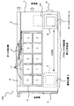
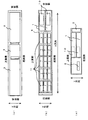
<ライブラリ装置100の構成例>
まず、図1、図2を参照しながら、本実施形態のライブラリ装置100の構成例について説明する。図1は、ライブラリ装置100を上方から見た図(上面図)であり、図2は、ライブラリ装置100を側面及び背面から見た図(側面図)であり、図2(a)は、図1に示す第1の側面側からライブラリ装置100を見た図であり、図2(b)は、図1に示す第2の側面側からライブラリ装置100を見た図であり、図2(c)は、図1に示す背面側からライブラリ装置100を見た図である。なお、図2(b)では、アクセッサ機構5の図示を省略している。
<Configuration example of
First, a configuration example of the
本実施形態のライブラリ装置100は、ドライブ装置1、制御装置2、電源装置3、バックボード4、アクセッサ機構5、マガジン6、媒体7、LANコネクタ8、オペレーションパネル9と、を有して構成する。
The
マガジン6は、媒体7を収容するための媒体収容手段の一例である。本実施形態のマガジン6は、複数のセル(破線で区切られた部分)11を有しており、1つのセル11毎に媒体7を2つ収容することが可能なディープセル方式を採用している。本実施形態のマガジン6は、図2(b)に示すように、ライブラリ装置100の高さ方向(Y方向)に3段のディープセルを備え、ライブラリ装置100の奥行き方向(X方向)に5列のディープセルを備えている。また、マガジン6は、図1に示すように、ライブラリ装置100の前面側(正面側)から取り外すことが可能な構成になっている。
The
媒体7は、コンピュータが読み取り可能な媒体であり、例えば、磁気テープを包装したカートリッジ等が挙げられる。
The
アクセッサ機構5は、媒体7を移送するための媒体移送手段の一例である。本実施形態のアクセッサ機構5は、図1に示すように、ライブラリ装置100の背面側から前面側へ移動したり、または、ライブラリ装置100前面側から背面側へ移動したりすることができる(図1、図2(b)のX方向)。
The
また、アクセッサ機構5は、図2(b)に示すように、ライブラリ装置100の底面側から上面側に移動したり、または、ライブラリ装置100の上面側から底面側に移動したりすることができる(図2(b)のY方向)。
Further, as shown in FIG. 2B, the
なお、本実施形態のライブラリ装置100は、アクセッサ機構5を図1、図2(b)のX方向に移動する際に使用するモータは、ステッピングモータを使用し、図2(b)のY方向に移動する際に使用するモータは、DCモータを使用し、別々のモータを使用してアクセッサ機構5の移動を制御するように構成する。
In the
また、アクセッサ機構5は、例えば、所定の媒体7に対する読み出し又は書き込みの指示があった場合に、その媒体7の移送を行う。具体的には、アクセッサ機構5は、制御装置2からの指示に従って、制御装置2から指定された媒体7をマガジン6から抜き出し、その抜き出した媒体7をドライブ装置1に移送し、スロット10に差し込む。そして、アクセッサ機構5は、媒体7の読み出し又は書き込みが終わると、ドライブ装置1のスロット10から媒体7を抜き出し、その抜き出した媒体7を収容元のマガジン6に移送し、収容元のセル11に媒体7を差し込むことになる。
The
なお、ディープセル方式では、指定された媒体7がセル11の奥側(図1の第1の側面側)に収容されている場合は、そのセル11の手前(図1の第2の側面側)に収容されている媒体7を空きセルに一時的に退避させる退避動作が必要となるが、アクセッサ機構5は、その退避動作も行うことになる。
In the deep cell method, when the designated
ドライブ装置1は、媒体7に格納されている情報を読み出したり、媒体7に情報を書き込んだりする媒体読書手段の一例である。本実施形態のドライブ装置1は、スロット10に差し込まれた媒体7からデータを読み出したり、または、媒体7にデータを書き込んだりする。本実施形態では、図2(b)及び図2(c)に示すように、2つのドライブ装置1がライブラリ装置100の高さ方向(図2(b)、(c)のY方向)で上下に重なって配置されている。
The drive device 1 is an example of a medium reading unit that reads information stored in the
制御装置2は、ライブラリ装置100の制御を行う制御手段の一例である。本実施形態の制御装置2は、図示しないホスト等から媒体7の読み出し又は書き込み指示を受け付けた場合に、アクセッサ機構5を用いてマガジン6内に収容されている媒体7をドライブ装置1に搬送し、ドライブ装置1で媒体7の読み出し又は書き込み処理を行い、再び、マガジン6内に媒体7を収容するように制御する。
The
電源装置3は、ライブラリ装置100を動作させるための電気を供給する電源手段の一例である。
The
バックボード4は、ライブラリ装置100内の各装置(デバイス)を電気的に接続する接続手段の一例である。本実施形態のバックボード4は、ドライブ装置1、制御装置2、電源装置3のそれぞれがバックボード4に接続できるように構成している。また、LANコネクタ8、オペレーションパネル9は、ケーブルを介してバックボード4に接続できるように構成している。また、アクセッサ機構5は、フロントパネルにケーブルを介して接続し、フロントパネルを中継して最終的にバックボード4に接続できるように構成している。
The
LANコネクタ8は、ライブラリ装置100をローカルエリアネットワークに接続するためのコネクタである。
The
オペレーションパネル9は、各種操作を受け付けたり、各種情報を表示したりする。
The
本実施形態のライブラリ装置100は、図1、図2(a)に示すように、第1の側面に沿って制御装置2と電源装置3とが配置されるように構成している。また、制御装置2と電源装置3との間にバックボード4が配置されるように構成している。なお、バックボード4は、ライブラリ装置100の奥行き方向(X方向)のほぼ中央部分に配置されるように構成している。
As shown in FIGS. 1 and 2A, the
また、本実施形態のライブラリ装置100は、図1に示すように、第1の側面に沿って配置された制御装置2、バックボード4、電源装置3の隣に、マガジン6が装着され、且つ、電源装置3の隣にドライブ装置1が配置されるように構成している。即ち、ドライブ装置1は、スロット10における媒体7の出入口(抜き差し口)が第2の側面の方向を向くように構成している。
Further, as shown in FIG. 1, the
また、本実施形態のライブラリ装置100は、図1に示すように、マガジン6の各ディープセルにおける媒体7の出入口(抜き差し口)が第2の側面の方向を向くように構成している。そして、スロット10における媒体7の出入口と各ディープセルにおける媒体7の出入口とが並列となるように構成している。
Further, as shown in FIG. 1, the
また、本実施形態のライブラリ装置100は、図1に示すように、第2の側面側にアクセッサ機構5が配置されるように構成している。また、第2の側面に沿って、アクセッサ機構5の可動範囲(ライブラリ装置100のX方向における可動範囲)である空間を設けるように構成している。本実施形態のライブラリ装置100は、スロット10における媒体7の出入口と各ディープセルにおける媒体7の出入口とがこの空間の方を向いており、アクセッサ機構5はそれらの出入口から媒体7の抜き差しを行う。
Further, as shown in FIG. 1, the
また、本実施形態のライブラリ装置100は、図1に示すように、バックボード4を1つだけ備えるように構成しており、そのバックボード4に、制御装置2、電源装置3、ドライブ装置1が直接接続できるように構成している。即ち、1つのバックボード4を3つの装置2,3,1で共有できるように構成している。
Further, as shown in FIG. 1, the
3つの装置2,3,1は、バックボード4から着脱可能な構成になっており、制御装置2は、ライブラリ装置100の前面側からバックボード4に着脱可能な構成になっている。例えば、制御装置2は、図1に示すように、前面側(図1中の矢印方向)に抜き出すことができるように構成している。また、電源装置3、ドライブ装置1は、ライブラリ装置100の背面側からバックボード4に着脱可能な構成になっている。例えば、電源装置3、ドライブ装置1は、図1に示すように、背面側(図1中の矢印方向)に抜き出すことができるように構成している。
The three
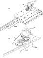
<アクセッサ機構5の内部概略構成例>
次に、図3を参照しながら、アクセッサ機構5の内部概略構成例について説明する。図3は、アクセッサ機構5の内部概略構成例を示す図であり、アクセッサ機構5を図1に示すX方向に移動する際の駆動構成例を示している。図3(a)は、アクセッサ機構5の内部概略構成例を示し、図3(b)は、図3(a)のステッピングモータ51と複数のギア52との部分の拡大構成例を示している。
<Example of internal schematic configuration of
Next, an internal schematic configuration example of the
アクセッサ機構5は、図3(a)、(b)に示すように、ステッピングモータ51と、複数のギア52と、を有しており、ステッピングモータ51の回転駆動に伴い、複数のギア52が回転し、アクセッサ機構5が図1、図3(a)、(b)に示すX方向に移動することになる。また、図3(b)に示すように、アクセッサ機構5を構成する一部のギア521には、エンコーダセンサ53が設けられており、そのエンコーダセンサ53でカウントしたエンコーダカウント数を制御装置2が取得することになる。
As shown in FIGS. 3A and 3B, the
本実施形態のエンコーダセンサ53は、公知のエンコーダセンサであり、光を発光する発光部と、光を受光する受光部と、を有して構成する。本実施形態のエンコーダセンサ53は、発光部で発光した光が一部のギア521に設けられたスリットを通過し、そのスリットを通過した光を受光部が受光することで、エンコーダセンサ53がHigh、Lowの出力信号を生成し、その出力信号を基に、エンコーダカウント数をカウントすることになる。本実施形態では、図3(b)に示すように、一部のギア521に2つのエンコーダセンサ53を設け、その2つのエンコーダセンサ53でカウントしたエンコーダカウント数を制御装置2が取得し、制御装置2は、2つのエンコーダセンサ53の位相をずらし、精度の高いエンコーダカウント数を取得する。
The
なお、図3(b)では、一部のギア521に2つのエンコーダセンサ53を設け、その2つのエンコーダセンサ53でカウントしたエンコーダカウント数を制御装置2が取得し、制御装置2は、2つのエンコーダセンサ53から取得したエンコーダカウント数を用いて精度の高いエンコーダカウント数を取得することにした。しかし、一部のギア521に1つのエンコーダセンサ53を設け、その1つのエンコーダセンサ53でカウントしたエンコーダカウント数を制御装置2が取得する構成にすることも可能である。
In FIG. 3B, two
<制御装置2の内部構成例>
次に、図4を参照しながら、本実施形態の制御装置2の内部構成例について説明する。
<Internal configuration example of
Next, an example of the internal configuration of the
本実施形態の制御装置2は、移動制御手段101と、確認手段102と、調整手段103と、メモリ104と、を有して構成する。移動制御手段101と、確認手段102と、調整手段103と、は1つのファームウェアで実現することができる。
The
移動制御手段101は、アクセッサ機構5の移動を制御するものである。移動制御手段101は、アクセッサ機構5の移動距離に応じたパルス数だけ図3に示すステッピングモータ51を駆動することによって、アクセッサ機構5を移動させる。
The movement control means 101 controls the movement of the
確認手段102は、アクセッサ機構5の移動距離を確認するものである。確認手段102は、アクセッサ機構5の移動距離に応じたパルス数だけ図3に示すステッピングモータ51を駆動した場合に、そのアクセッサ機構5の移動に応じて図3に示すエンコーダセンサ53で実際にカウントされたエンコーダカウント数と、アクセッサ機構5の移動距離に応じたパルス数に基づいて想定される想定エンコーダカウント数と、を比較し、アクセッサ機構5の移動距離を確認する。想定エンコーダカウント数は、アクセッサ機構5の移動距離に応じたパルス数×確認係数=想定エンコーダカウント数となる。
The confirmation means 102 confirms the moving distance of the
調整手段103は、アクセッサ機構5の移動距離に応じたパルス数に基づいて想定されるエンコーダカウント数を算出する際に使用する確認係数を決定する。調整手段103は、例えば、ライブラリ装置100の電源ON時等に、上記確認係数を決定する。これにより、確認手段102は、調整手段102で決定した確認係数を基に、アクセッサ機構5の移動距離に応じたパルス数に基づいて想定されるエンコーダカウント数を算出し、その算出した想定エンコーダカウント数と、アクセッサ機構5の移動に応じて図3に示すエンコーダセンサ53で実際にカウントされたエンコーダカウント数と、を比較し、アクセッサ機構5の移動距離を確認することができる。なお、調整手段103で行う確認係数の決定は、ライブラリ装置100の電源ON時等に限定するものではなく、任意のタイミングで行うことが可能である。
The adjusting
メモリ104は、制御装置2で使用する各種情報を管理する。
The
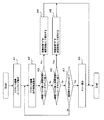
<ライブラリ装置100の処理動作例>
次に、図5、図6を参照しながら、本実施形態のライブラリ装置100の処理動作例について説明する。図5は、ライブラリ装置100の電源ON時の処理動作例を示し、図6は、アクセッサ機構5の指定位置確認動作時の処理動作例を示す。指定位置確認動作は、ライブラリ装置100の通常動作時に行われる。
<Example of processing operation of
Next, an example of processing operation of the
<ライブラリ装置100の電源ON時の処理動作例>
まず、図5を参照しながら、ライブラリ装置100の電源ON時の処理動作例について説明する。
<Example of processing operation when the
First, an example of processing operation when the
ライブラリ装置100の電源をONにした時に、制御装置2は、アクセッサ機構5のイニシャライズ動作を行う(ステップA1)。イニシャライズ動作は、公知の動作であるため、具体的な処理は割愛する。この時、制御装置2は、エンコーダセンサ53でカウントされたエンコーダカウント数を初期化し、エンコーダカウント数を0にしておく。
When the
次に、移動制御手段101は、アクセッサ機構5の走行路確認動作を行い、アクセッサ機構5の走行路に障害物がないか否かを確認する(ステップA2)。走行路確認動作は、アクセッサ機構5を、ホームポジションの位置(図1に示すAの位置)から一番遠い媒体7の最終位置(図1に示すBの位置)まで移動させ、ホームポジションの位置Aから最終位置Bまでの走行路に障害物がないか否かを確認する。
Next, the movement control means 101 performs a traveling path confirmation operation of the
制御装置2は、ホームポジションの位置Aから最終位置Bまでアクセッサ機構5を移動させるのに必要な移動パルス数を予めメモリ104等で管理しているため、移動制御手段101は、そのメモリ104等で管理している移動パルス数だけステッピングモータ51を駆動し、アクセッサ機構5をホームポジションの位置Aから最終位置Bまで移動し、走行路確認動作を行うことになる。
Since the
なお、調整手段103は、移動パルス数だけステッピングモータ51を駆動した時までにエンコーダセンサ53でカウントされたエンコーダカウント数を取得し、移動パルス数と、エンコーダカウント数と、を基に、確認係数として使用する調整係数を決定する(ステップA3〜A6)。確認係数は、後述する指定位置確認動作の処理で確認手段102が上記想定エンコーダカウント数を算出する際に使用する係数である。
The adjusting means 103 obtains the encoder count number counted by the
本実施形態では、制御装置2は、確認係数として使用する複数の調整係数(調整係数A、調整係数B)を予めメモリ104等に管理しておき(但し、調整係数A≠調整係数B)、調整手段103は、移動パルス数と、エンコーダカウント数と、メモリ104等で管理する複数の調整係数(調整係数A、調整係数B)と、を基に、確認係数として使用する調整係数を決定する(ステップA3〜A6)。
In the present embodiment, the
具体的には、調整手段103は、移動パルス数と、エンコーダカウント数と、調整係数Aと、の関係が以下の式1を満足するか否かを判定する(ステップA3)。 Specifically, the adjustment means 103 determines whether or not the relationship among the number of moving pulses, the encoder count number, and the adjustment coefficient A satisfies the following expression 1 (step A3).
移動パルス数×調整係数A=エンコーダカウント数・・・式1 Number of moving pulses x adjustment factor A = number of encoder counts (1)
調整手段103は、上記の式1の条件を満たす場合は(ステップA3/Yes)、確認係数として調整係数Aを使用すると決定し(ステップA4)、処理を終了する(End)。
If the condition of Equation 1 above is satisfied (step A3 / Yes), the
また、上記の式1の条件を満たさない場合は(ステップA3/No)、移動パルス数と、エンコーダカウント数と、調整係数Bと、の関係が以下の式2を満足するか否かを判定する(ステップA5)。
If the condition of the above expression 1 is not satisfied (step A3 / No), it is determined whether or not the relationship among the number of moving pulses, the encoder count number, and the adjustment coefficient B satisfies the following
移動パルス数×調整係数B=エンコーダカウント数・・・式2
Number of moving pulses x adjustment factor B = number of encoder counts ...
調整手段103は、上記の式2の条件を満たす場合は(ステップA5/Yes)、確認係数として調整係数Bを使用すると決定し(ステップA6)、処理を終了する(End)。
If the condition of
また、上記の式2の条件を満たさない場合は(ステップA5/No)、調整手段103は、移動制御手段101が走行路確認動作をN(Nは、任意の整数)回行ったか否かを判定し(ステップA7)、走行路確認動作をN回行っていない場合は(ステップA7/No)、移動制御手段101は、再び走行路確認動作を行い(ステップA2)、調整手段103は、移動パルス数だけステッピングモータ51を駆動した時までにエンコーダセンサ53でカウントされたエンコーダカウント数を取得し、移動パルス数と、エンコーダカウント数と、を基に、確認係数として使用する調整係数を決定する(ステップA3〜A6)。
If the condition of the
調整手段103は、移動制御手段101が走行路確認動作をN回行っても、確認係数として使用する調整係数を決定することができない場合は(ステップA7/Yes)、エラー通知を行い(ステップA8)、処理を終了する(End)。エラー通知としては、確認係数を決定できない旨をユーザに通知する等の処理を行うことになる。 If the adjustment means 103 cannot be determined as the confirmation coefficient even after the movement control means 101 performs the travel path confirmation operation N times (step A7 / Yes), the adjustment means 103 performs error notification (step A8). ), And ends the processing (End). As the error notification, processing such as notifying the user that the confirmation coefficient cannot be determined is performed.
<確認係数の決定時の具体例>
次に、上述した確認係数の決定時の具体例について説明する。
<Specific example when determining confirmation factor>
Next, a specific example when determining the confirmation coefficient described above will be described.
例えば、式1の調整係数Aが0.8、式2の調整係数Bが0.9のアクセッサ機構5があると仮定する。また、ホームポジションの位置(図1に示すAの位置)から一番遠い媒体7の最終位置(図1に示すBの位置)までアクセッサ機構5を移動させるのに必要な移動パルス数を1000パルスとする。
For example, it is assumed that there is an
調整手段103は、移動パルス数を1000パルスとしてステッピングモータ51を駆動した時までにエンコーダセンサ53でカウントされたエンコーダカウント数を取得し、その取得したエンコーダカウント数が900とする。この場合、移動パルス数と、エンコーダカウント数と、の関係は、移動パルス数(1000)×調整係数B(0.9)=エンコーダカウント数(900)となり、上記式2の条件に該当するため、確認係数として調整係数Bを使用すると決定する。
The adjusting means 103 acquires the encoder count number counted by the
これにより、調整手段103は、移動パルス数だけステッピングモータ51を駆動した時までにエンコーダセンサ53でカウントされたカウント数と、移動パルス数と、の関係を基に、確認係数として使用する調整係数を決定することができる。
Thereby, the adjustment means 103 uses the adjustment coefficient used as a confirmation coefficient based on the relationship between the count number counted by the
なお、上記処理では、ホームポジションの位置Aから最終位置Bまでアクセッサ機構5を移動させるのに必要な移動パルス数を用いて、確認係数として使用する調整係数を決定することにした。しかし、確認係数として使用する調整係数を決定する際に使用するパルス数は、上述した移動パルス数に限定するものではなく、ホームポジションの位置Aから所定の位置までアクセッサ機構5を移動させるのに必要な所定のパルス数を用いて、確認係数として使用する調整係数を決定するようにすることも可能である。この場合は、ホームポジションの位置Aから所定の位置までアクセッサ機構5を移動させるのに必要な所定のパルス数だけステッピングモータ51を駆動した時までにエンコーダセンサ53でカウントされたエンコーダカウント数を取得し、上記所定のパルス数と、エンコーダカウント数と、を基に、確認係数として使用する調整係数を決定することになる。
In the above processing, the adjustment coefficient used as the confirmation coefficient is determined using the number of movement pulses necessary to move the
<アクセッサ機構5の指定位置確認動作時の処理動作例>
次に、図6を参照しながら、アクセッサ機構5の指定位置確認動作時の処理動作例について説明する。
<Example of processing operation when the specified position of the
Next, an example of processing operation at the time of the designated position confirmation operation of the
制御装置2は、通常動作時にアクセッサ機構5の移動指示を受け付けた場合に、移動制御手段101は、指定位置移動動作を行い、その移動指示で受け付けた指定位置(ユーザから指定されたセル11の位置)までアクセッサ機構5を移動させる(ステップB1)。
When the
制御装置2は、ホームポジションの位置Aから指定位置(各セル11の位置)までアクセッサ機構5を移動させるのに必要なパルス数を予めメモリ104等で管理しているため、移動制御手段101は、ホームポジションの位置Aから指定位置まで移動させるのに必要なパルス数だけステッピングモータ51を駆動し、アクセッサ機構5をホームポジションの位置Aから指定位置まで移動し、指定位置移動動作を行うことになる。
Since the
なお、確認手段102は、指定位置まで移動させるのに必要なパルス数だけステッピングモータ51を駆動した時までにエンコーダセンサ53でカウントされたエンコーダカウント数を取得し、指定位置まで移動させるのに必要なパルス数と、エンコーダカウント数と、を基に、以下の式3を用いてアクセッサ機構5の指定位置確認を行い、指定位置まで移動させるのに必要なパルス数と、エンコーダカウント数と、に相関関係があるか否かを確認する(ステップB2)。但し、以下の式3の確認係数Xは、図5の処理で調整手段103が確認係数として決定した調整係数を使用する(上述した具体例では、調整係数B)。
The confirmation means 102 is necessary to acquire the encoder count number counted by the
指定位置まで移動させるのに必要なパルス数×確認係数X=エンコーダカウント数・・・式3
Number of pulses required to move to the specified position x confirmation coefficient X = number of encoder counts ...
確認手段102は、上記の式3の条件を満たす場合は(ステップB2/Yes)、指定位置まで移動させるのに必要なパルス数と、エンコーダカウント数と、に相関関係があると判定し、アクセッサ機構5が指定位置まで移動したと判断し、処理を終了する(End)。
If the condition of the
即ち、上記式3に示す、指定位置までに移動させるのに必要なパルス数×確認係数Xにより得られるエンコーダカウント数は、想定エンコーダカウント数になるため、上記式3の条件を満たす場合は、エンコーダセンサ53でカウントされたエンコーダカウント数は想定エンコーダカウント数と一致することになる。このため、確認手段102は、上記の式3の条件を満たす場合は、指定位置まで移動させるのに必要なパルス数と、エンコーダカウント数と、に相関関係があると判定し、アクセッサ機構5が指定位置まで移動したと判断することができる。
That is, since the encoder count number obtained by the number of pulses required to move to the specified position shown in the
また、確認手段102は、上記の式3の条件を満たさない場合は(ステップB2/No)、指定位置まで移動させるのに必要なパルス数と、エンコーダカウント数と、に相関関係がないと判定し、アクセッサ機構5が指定位置まで移動していないと判断する。
In addition, when the condition of the
即ち、上記式3の条件を満たさない場合は、エンコーダセンサ53でカウントされたエンコーダカウント数は想定エンコーダカウント数と一致しないことになる。このため、確認手段102は、上記の式3の条件を満たさない場合は、指定位置まで移動させるのに必要なパルス数と、エンコーダカウント数と、に相関関係がないと判定し、アクセッサ機構5が指定位置まで移動していないと判断することができる。
That is, when the condition of the
この場合、確認手段102は、移動制御手段101が指定位置移動動作をN(Nは、任意の整数)回行ったか否かを判定し(ステップB3)、N回行っていない場合は(ステップB3/No)、移動制御手段101は、再び指定位置移動動作を行い(ステップB1)、確認手段102は、指定位置まで移動させるのに必要なパルス数だけステッピングモータ51を駆動した時までにエンコーダセンサ53でカウントされたエンコーダカウント数を取得し、その取得したパルス数と、エンコーダカウント数と、に相関関係があるか否かを確認する(ステップB2)。
In this case, the
確認手段102は、移動制御手段101が指定位置移動動作をN回行っても、上記式3の条件を満たすことができず、指定位置まで移動させるのに必要なパルス数と、エンコーダカウント数と、に相関関係がないと判定した場合は(ステップB3/Yes)、エラー通知を行い(ステップB4)、処理を終了する(End)。エラー通知としては、アクセッサ機構5が指定位置まで移動できない旨をユーザに通知する等の処理を行うことになる。
Even if the movement control means 101 performs the designated position movement operation N times, the confirmation means 102 cannot satisfy the condition of the
<本実施形態のライブラリ装置100の作用・効果>
このように、本実施形態のライブラリ装置100の制御装置2は、複数の調整係数(調整係数A、調整係数B;但し、調整係数A≠調整係数B)を予めメモリ104等で管理する。そして、移動制御手段101は、予め定められた移動パルス数だけステッピングモータ51を駆動し、走行路確認動作を行うと共に、調整手段103は、移動パルス数だけステッピングモータ51を駆動した時までにエンコーダセンサ53でカウントされたエンコーダカウント数を取得する。そして、調整手段103は、移動パルス数と、エンコーダカウント数と、の関係が、移動パルス数×調整係数=エンコーダコーダカウント数の関係となる調整係数を、制御装置2のメモリ104等で管理する複数の調整係数(調整係数A、調整係数B)の中から決定し、該決定した調整係数を確認係数として決定する。
<Operation and Effect of
As described above, the
これにより、本実施形態のライブラリ装置100は、指定位置まで移動させるのに必要なステッピングモータ51のパルス数と、エンコーダカウント数と、の関係(指定位置まで移動させるのに必要なパルス数×確認係数X=実際のエンコーダカウント数の関係)が変わってしまっても、調整手段103が確認係数Xを調整することになるため、確認手段102は、アクセッサ機構5の移動距離をエンコーダセンサ53でカウントしたエンコーダカウント数で確認することができる。
As a result, the
また、本実施形態のライブラリ装置100は、移動制御手段101と、確認手段102と、調整手段103と、は1つのファームウェアで実現することができるため、1つのファームウェアでアクセッサ機構5の移動制御を実現することができる。また、本実施形態のライブラリ装置100は、ハードウェア構成を変更することなく、指定位置まで移動させるのに必要なパルス数と、エンコーダカウント数と、の関係を調整することができる。
In the
なお、上述する実施形態は、本発明の好適な実施形態であり、上記実施形態のみに本発明の範囲を限定するものではなく、本発明の要旨を逸脱しない範囲において種々の変更を施した形態での実施が可能である。 The above-described embodiment is a preferred embodiment of the present invention, and the scope of the present invention is not limited to the above-described embodiment alone, and various modifications are made without departing from the gist of the present invention. Implementation is possible.
例えば、上述した実施形態では、制御装置2は、図1に示すアクセッサ機構5のX方向の移動制御について説明した。しかし、図2に示すアクセッサ機構5のY方向の移動制御についても、ステッピングモータを使用する場合には、X方向の移動制御と同様な制御を行うことも可能である。
For example, in the above-described embodiment, the
また、上述した実施形態では、調整手段103は、ライブラリ装置100の電源ON時に、図5に示す処理動作を行い、確認係数として使用する調整係数を決定し、確認手段102は、調整手段103が決定した確認係数を用いて、図6に示す指定位置確認動作を行うことにした。しかし、確認係数として使用する調整係数を決定するタイミングは、ライブラリ装置100の電源ON時に限定するものではなく、任意のタイミングで行うことも可能である。例えば、オペレーションパネル9等から、確認係数として使用する調整係数の決定開始指示を受け付けた場合に、調整手段103が図5に示す処理動作を行うようにすることも可能である。また、図6に示す処理動作において、ステップB4のエラー通知を行うことになった場合に、調整手段103が自動的に図5に示す処理動作を行うようにすることも可能である。即ち、調整手段103は、確認手段102が使用する前に確認係数を調整したり、確認手段102が使用した後に確認係数を調整したりすることが可能である。
In the above-described embodiment, the
また、上述した本実施形態におけるライブラリ装置100を構成する各装置における制御動作は、ハードウェア、または、ソフトウェア、あるいは、両者の複合構成を用いて実行することも可能である。
Further, the control operation in each device constituting the
なお、ソフトウェアを用いて処理を実行する場合には、処理シーケンスを記録したプログラムを、専用のハードウェアに組み込まれているコンピュータ内のメモリにインストールして実行させることが可能である。あるいは、各種処理が実行可能な汎用コンピュータにプログラムをインストールして実行させることが可能である。 In the case of executing processing using software, it is possible to install and execute a program in which a processing sequence is recorded in a memory in a computer incorporated in dedicated hardware. Alternatively, the program can be installed and executed on a general-purpose computer capable of executing various processes.
例えば、プログラムは、記録媒体としてのハードディスクやROM(Read Only Memory)に予め記録しておくことが可能である。あるいは、プログラムは、リムーバブル記録媒体に、一時的、あるいは、永続的に格納(記録)しておくことが可能である。このようなリムーバブル記録媒体は、いわゆるパッケージソフトウエアとして提供することが可能である。なお、リムーバブル記録媒体としては、フロッピー(登録商標)ディスク、CD-ROM(Compact Disc Read Only Memory)、MO(Magneto optical)ディスク、DVD(Digital Versatile Disc)、磁気ディスク、半導体メモリなどが挙げられる。 For example, the program can be recorded in advance on a hard disk or ROM (Read Only Memory) as a recording medium. Alternatively, the program can be stored (recorded) temporarily or permanently in a removable recording medium. Such a removable recording medium can be provided as so-called package software. Examples of the removable recording medium include a floppy (registered trademark) disk, a CD-ROM (Compact Disc Read Only Memory), an MO (Magneto optical) disk, a DVD (Digital Versatile Disc), a magnetic disk, and a semiconductor memory.
なお、プログラムは、上述したようなリムーバブル記録媒体からコンピュータにインストールすることになる。また、ダウンロードサイトから、コンピュータに無線転送することになる。また、ネットワークを介して、コンピュータに有線で転送することになる。 The program is installed in the computer from the removable recording medium as described above. In addition, it is wirelessly transferred from the download site to the computer. In addition, it is transferred to the computer via a network by wire.
また、本実施形態におけるライブラリ装置100は、上記実施形態で説明した処理動作に従って時系列的に実行されるのみならず、処理を実行する装置の処理能力、あるいは、必要に応じて並列的にあるいは個別に実行するように構築することも可能である。
In addition, the
100 ライブラリ装置
1 ドライブ装置
2 制御装置
3 電源装置
4 バックボード
5 アクセッサ機構
6 マガジン
7 媒体
8 LANコネクタ
9 オペレーションパネル
51 ステッピングモータ
52 ギア
53 エンコードセンサ
101 移動制御手段
102 確認手段
103 調整手段
104 メモリ(管理手段)
DESCRIPTION OF
Claims (7)
前記媒体に格納された情報の読み出しと、前記媒体に対する情報の書き込みと、の少なくとも1つを行う媒体読書手段と、
前記媒体収容手段と、前記媒体読書手段と、の間で前記媒体を移送する媒体移送手段と、
前記媒体移送手段を制御する制御手段と、を有し、
前記制御手段は、
前記媒体移送手段の移動距離に応じたパルス数だけステッピングモータを駆動することによって、前記媒体移送手段を移動させる移動制御手段と、
前記パルス数だけ前記ステッピングモータを駆動した場合に前記媒体移送手段の移動に応じてエンコーダセンサでカウントされる実際のエンコーダカウント数と、前記パルス数に基づいて想定される想定エンコーダカウント数と、を比較する確認手段と、
前記パルス数に基づいて想定される想定エンコーダカウント数を算出する際に使用する確認係数を決定する調整手段と、
を有することを特徴とするライブラリ装置。 Medium accommodating means capable of accommodating a plurality of computer-readable media;
Medium reading means for performing at least one of reading information stored in the medium and writing information to the medium;
Medium transfer means for transferring the medium between the medium accommodation means and the medium reading means;
Control means for controlling the medium transfer means,
The control means includes
A movement control means for moving the medium transfer means by driving a stepping motor by the number of pulses corresponding to the moving distance of the medium transfer means;
When the stepping motor is driven by the number of pulses, an actual encoder count number counted by an encoder sensor in accordance with the movement of the medium transfer unit, and an assumed encoder count number assumed based on the pulse number, Confirmation means for comparison;
Adjusting means for determining a confirmation coefficient used when calculating an assumed encoder count number assumed based on the number of pulses;
A library apparatus comprising:
所定のパルス数だけ前記ステッピングモータを駆動した時までに前記エンコーダセンサでカウントされたカウント数と、前記所定のパルス数と、の関係を基に、前記確認係数を決定することを特徴とする請求項1記載のライブラリ装置。 The adjusting means includes
The confirmation coefficient is determined based on a relationship between a count number counted by the encoder sensor until the stepping motor is driven by a predetermined pulse number and the predetermined pulse number. Item 2. The library device according to Item 1.
前記パルス数×前記確認係数=前記想定エンコーダカウント数の関係になっており、
前記調整手段は、
前記カウント数と、前記所定のパルス数と、の関係が、前記所定のパルス数×調整係数=前記カウント数の関係となる前記調整係数を、前記確認係数として決定することを特徴とする請求項2記載のライブラリ装置。 The assumed encoder count number assumed based on the number of pulses is
The number of pulses × the confirmation coefficient = the assumed encoder count number.
The adjusting means includes
2. The adjustment coefficient for which the relationship between the count number and the predetermined pulse number is such that the predetermined pulse number × adjustment coefficient = the count number is determined as the confirmation coefficient. 2. The library apparatus according to 2.
前記調整手段は、
前記カウント数と、前記所定のパルス数と、の関係が、前記所定のパルス数×調整係数=前記カウント数の関係となる前記調整係数を、前記管理手段で管理する複数の前記調整係数の中から決定することを特徴とする請求項3記載のライブラリ装置。 Management means for managing a plurality of the adjustment factors;
The adjusting means includes
Among the plurality of adjustment coefficients managed by the management means, the adjustment coefficient is such that the relationship between the count number and the predetermined pulse number is the relationship of the predetermined pulse number × the adjustment coefficient = the count number. 4. The library device according to claim 3, wherein the library device is determined from:
前記媒体に格納された情報の読み出しと、前記媒体に対する情報の書き込みと、の少なくとも1つを行う媒体読書手段と、
前記媒体収容手段と、前記媒体読書手段と、の間で前記媒体を移送する媒体移送手段と、
前記媒体移送手段の移動距離に応じたパルス数だけステッピングモータを駆動することによって、前記媒体移送手段を移動させる制御手段と、を有し、
前記制御手段は、
調整指示を受け付けた場合に、前記媒体移送手段の移動距離に応じたパルス数に基づいて想定される想定エンコーダカウント数を算出する際に使用する確認係数を決定する調整手段と、
前記媒体移送手段の移動距離を確認する場合に、前記調整手段で決定した前記確認係数及び前記媒体移送手段の移動距離に応じたパルス数に基づいて想定される想定エンコーダカウント数と、前記媒体移送手段の移動距離に応じたパルス数だけ前記ステッピングモータを駆動した場合にエンコーダセンサでカウントされる実際のエンコーダカウント数と、を比較する確認手段と、
を有することを特徴とするライブラリ装置。 Medium accommodating means capable of accommodating a plurality of computer-readable media;
Medium reading means for performing at least one of reading information stored in the medium and writing information to the medium;
Medium transfer means for transferring the medium between the medium accommodation means and the medium reading means;
Control means for moving the medium transfer means by driving the stepping motor by the number of pulses corresponding to the moving distance of the medium transfer means,
The control means includes
An adjusting means for determining a confirmation coefficient to be used when calculating an assumed encoder count based on the number of pulses corresponding to the moving distance of the medium transporting means when receiving an adjustment instruction;
When confirming the movement distance of the medium transfer means, the assumed encoder count number assumed based on the confirmation coefficient determined by the adjustment means and the number of pulses corresponding to the movement distance of the medium transfer means, and the medium transfer Checking means for comparing the actual encoder count number counted by the encoder sensor when the stepping motor is driven by the number of pulses corresponding to the moving distance of the means;
A library apparatus comprising:
前記制御手段は、
前記媒体移送手段の移動距離に応じたパルス数だけステッピングモータを駆動することによって、前記媒体移送手段を移動させる移動制御工程と、
前記パルス数だけ前記ステッピングモータを駆動した場合に前記媒体移送手段の移動に応じてカウントされる実際のエンコーダカウント数と、前記パルス数に基づいて想定される想定エンコーダカウント数と、を比較する確認工程と、
前記パルス数に基づいて想定される想定エンコーダカウント数を算出する際に使用する確認係数を決定する調整工程と、
を行うことを特徴とする制御方法。 Medium accommodating means capable of accommodating a plurality of computer-readable media, medium reading means for performing at least one of reading information stored in the medium and writing information to the medium, and the medium accommodating means And a medium reading means for transferring the medium between the medium reading means and a control means for controlling the medium transferring means.
The control means includes
A movement control step of moving the medium transfer means by driving the stepping motor by the number of pulses corresponding to the moving distance of the medium transfer means;
Confirmation of comparing the actual encoder count number counted according to the movement of the medium transfer means when the stepping motor is driven by the number of pulses with the assumed encoder count number assumed based on the pulse number Process,
An adjustment step for determining a confirmation coefficient used when calculating an assumed encoder count number assumed based on the number of pulses;
The control method characterized by performing.
前記媒体移送手段の移動距離に応じたパルス数だけステッピングモータを駆動することによって、前記媒体移送手段を移動させる移動制御処理と、
前記パルス数だけ前記ステッピングモータを駆動した場合に前記媒体移送手段の移動に応じてカウントされる実際のエンコーダカウント数と、前記パルス数に基づいて想定される想定エンコーダカウント数と、を比較する確認処理と、
前記パルス数に基づいて想定される想定エンコーダカウント数を算出する際に使用する確認係数を決定する調整処理と、
を、前記制御手段に実行させることを特徴とするプログラム。 Medium accommodating means capable of accommodating a plurality of computer-readable media, medium reading means for performing at least one of reading information stored in the medium and writing information to the medium, and the medium accommodating means And a medium reading means for transferring the medium between the medium reading means and a control means for controlling the medium transferring means, and a program to be executed by a library apparatus comprising:
A movement control process for moving the medium transfer means by driving the stepping motor by the number of pulses corresponding to the moving distance of the medium transfer means;
Confirmation of comparing the actual encoder count number counted according to the movement of the medium transfer means when the stepping motor is driven by the number of pulses with the assumed encoder count number assumed based on the pulse number Processing,
An adjustment process for determining a confirmation coefficient used when calculating an assumed encoder count number assumed based on the pulse number;
Is executed by the control means.
Priority Applications (4)
| Application Number | Priority Date | Filing Date | Title |
|---|---|---|---|
| JP2010068020A JP5432017B2 (en) | 2010-03-24 | 2010-03-24 | Library apparatus, control method and program |
| US13/636,424 US8953270B2 (en) | 2010-03-24 | 2011-03-03 | Library device, control method and program |
| PCT/JP2011/054996 WO2011118363A1 (en) | 2010-03-24 | 2011-03-03 | Library device, control method, and program |
| EP11759171.9A EP2551852B1 (en) | 2010-03-24 | 2011-03-03 | Library device, control method, and program |
Applications Claiming Priority (1)
| Application Number | Priority Date | Filing Date | Title |
|---|---|---|---|
| JP2010068020A JP5432017B2 (en) | 2010-03-24 | 2010-03-24 | Library apparatus, control method and program |
Publications (2)
| Publication Number | Publication Date |
|---|---|
| JP2011204293A JP2011204293A (en) | 2011-10-13 |
| JP5432017B2 true JP5432017B2 (en) | 2014-03-05 |
Family
ID=44672931
Family Applications (1)
| Application Number | Title | Priority Date | Filing Date |
|---|---|---|---|
| JP2010068020A Active JP5432017B2 (en) | 2010-03-24 | 2010-03-24 | Library apparatus, control method and program |
Country Status (4)
| Country | Link |
|---|---|
| US (1) | US8953270B2 (en) |
| EP (1) | EP2551852B1 (en) |
| JP (1) | JP5432017B2 (en) |
| WO (1) | WO2011118363A1 (en) |
Families Citing this family (3)
| Publication number | Priority date | Publication date | Assignee | Title |
|---|---|---|---|---|
| JP5871319B2 (en) * | 2012-03-29 | 2016-03-01 | Necプラットフォームズ株式会社 | Library device, computer program |
| JP2015084267A (en) * | 2013-10-25 | 2015-04-30 | 日本電気株式会社 | Library apparatus, library control method, and program |
| US10032474B2 (en) * | 2016-12-07 | 2018-07-24 | Quantum Corporation | Unsuccessful storage media movement handling in automated removable storage media environments |
Family Cites Families (13)
| Publication number | Priority date | Publication date | Assignee | Title |
|---|---|---|---|---|
| US4527262A (en) * | 1982-07-28 | 1985-07-02 | Manto Incorporated | Information storer and retriever |
| JPH0833401B2 (en) * | 1988-06-13 | 1996-03-29 | 住友金属鉱山株式会社 | Automatic sample feeder |
| JP3096334B2 (en) * | 1991-11-08 | 2000-10-10 | パイオニア株式会社 | Position detection device |
| DE4313373A1 (en) * | 1992-04-28 | 1993-11-04 | Docupoint Inc A California Cor | Archival storage unit for optical disc memory cassettes - incorporates grippers driven by stepping motor programmed in accordance with properties of disc drives installed in pairs |
| JPH09198755A (en) * | 1996-01-19 | 1997-07-31 | Fujitsu Ltd | Library device |
| US6008964A (en) * | 1997-11-14 | 1999-12-28 | Exabyte Corporation | Cartridge library and method of operation thereof |
| JPH11149696A (en) | 1997-11-19 | 1999-06-02 | Fujitsu Ltd | Library device and control method therefor |
| US6612499B2 (en) * | 2002-01-24 | 2003-09-02 | Exabyte Corporation | Calibration cartridge for automated cartridge library and method of using same |
| JP3891142B2 (en) * | 2003-04-23 | 2007-03-14 | 日本電気株式会社 | Cartridge transport and storage apparatus and method, cartridge transport and storage program, and storage medium |
| US7107121B2 (en) * | 2003-08-29 | 2006-09-12 | International Business Machines Corp. | Autonomic fiducial search pattern in an automated tape library |
| JP4159481B2 (en) * | 2004-01-22 | 2008-10-01 | Necパーソナルプロダクツ株式会社 | Library device |
| JP4665918B2 (en) * | 2007-03-06 | 2011-04-06 | 日本電気株式会社 | Library device |
| EP2189982B1 (en) | 2007-09-28 | 2014-03-05 | NEC Embedded Products, Ltd. | Housing cell, and magazine |
-
2010
- 2010-03-24 JP JP2010068020A patent/JP5432017B2/en active Active
-
2011
- 2011-03-03 WO PCT/JP2011/054996 patent/WO2011118363A1/en active Application Filing
- 2011-03-03 US US13/636,424 patent/US8953270B2/en not_active Expired - Fee Related
- 2011-03-03 EP EP11759171.9A patent/EP2551852B1/en active Active
Also Published As
| Publication number | Publication date |
|---|---|
| EP2551852A1 (en) | 2013-01-30 |
| EP2551852A4 (en) | 2017-04-26 |
| EP2551852B1 (en) | 2019-08-07 |
| JP2011204293A (en) | 2011-10-13 |
| US8953270B2 (en) | 2015-02-10 |
| US20130057979A1 (en) | 2013-03-07 |
| WO2011118363A1 (en) | 2011-09-29 |
Similar Documents
| Publication | Publication Date | Title |
|---|---|---|
| JP5432017B2 (en) | Library apparatus, control method and program | |
| JP5648941B2 (en) | System and method for high speed center correction of tape drives for flangeless tape paths | |
| US20150193145A1 (en) | Tape volume access block having data set information stored therein | |
| WO2015016922A1 (en) | Calibrating a tape drive | |
| US11127430B1 (en) | Robotic confirmation of column straightness | |
| JP2010079936A (en) | Media processing device, control method of media processing device and control program thereof | |
| JP2003196901A (en) | Magnetic tape cartridge library device | |
| US9147437B2 (en) | Library apparatus, magazine insertion detection method, and program | |
| JP5056047B2 (en) | Library apparatus and position control method thereof | |
| JP2011023068A (en) | Housing device, housing method, and library device | |
| JP5979558B2 (en) | Disk drive unit and disk device including the unit | |
| JP3891142B2 (en) | Cartridge transport and storage apparatus and method, cartridge transport and storage program, and storage medium | |
| US8873195B2 (en) | Library device, accessor, and method of positioning for library device | |
| JP4665918B2 (en) | Library device | |
| JP2023501919A (en) | Multi-spool tape recorder having removable mounts for supporting tape spool pairs | |
| US20080109117A1 (en) | Media processing device and control method for a media processing device | |
| JP2011150761A (en) | Library device | |
| CN101740056B (en) | Optical disk apparatus and driving method thereof | |
| JP2008243356A (en) | Library apparatus and positioning method in library apparatus | |
| JP5831932B2 (en) | Library device, model type identification method and program | |
| JP2003178510A (en) | Disk changer apparatus | |
| EP2551853B1 (en) | Library device | |
| JP2013062005A (en) | Accessor mobile device and accessor movement method | |
| JP2004178702A (en) | Magnetic tape library device | |
| JP6172728B2 (en) | Library apparatus and accessor control method in library apparatus |
Legal Events
| Date | Code | Title | Description |
|---|---|---|---|
| RD01 | Notification of change of attorney |
Free format text: JAPANESE INTERMEDIATE CODE: A7421 Effective date: 20110920 |
|
| A621 | Written request for application examination |
Free format text: JAPANESE INTERMEDIATE CODE: A621 Effective date: 20130218 |
|
| TRDD | Decision of grant or rejection written | ||
| A01 | Written decision to grant a patent or to grant a registration (utility model) |
Free format text: JAPANESE INTERMEDIATE CODE: A01 Effective date: 20131112 |
|
| A61 | First payment of annual fees (during grant procedure) |
Free format text: JAPANESE INTERMEDIATE CODE: A61 Effective date: 20131205 |
|
| R150 | Certificate of patent or registration of utility model |
Free format text: JAPANESE INTERMEDIATE CODE: R150 Ref document number: 5432017 Country of ref document: JP Free format text: JAPANESE INTERMEDIATE CODE: R150 |
|
| S111 | Request for change of ownership or part of ownership |
Free format text: JAPANESE INTERMEDIATE CODE: R313111 |
|
| R350 | Written notification of registration of transfer |
Free format text: JAPANESE INTERMEDIATE CODE: R350 |