JP5430371B2 - Recessed ceiling air conditioner - Google Patents
Recessed ceiling air conditioner Download PDFInfo
- Publication number
- JP5430371B2 JP5430371B2 JP2009271798A JP2009271798A JP5430371B2 JP 5430371 B2 JP5430371 B2 JP 5430371B2 JP 2009271798 A JP2009271798 A JP 2009271798A JP 2009271798 A JP2009271798 A JP 2009271798A JP 5430371 B2 JP5430371 B2 JP 5430371B2
- Authority
- JP
- Japan
- Prior art keywords
- wall
- air
- air outlet
- short side
- decorative panel
- Prior art date
- Legal status (The legal status is an assumption and is not a legal conclusion. Google has not performed a legal analysis and makes no representation as to the accuracy of the status listed.)
- Expired - Fee Related
Links
- 238000007789 sealing Methods 0.000 claims description 3
- 238000005452 bending Methods 0.000 claims 1
- 230000005494 condensation Effects 0.000 description 10
- 238000009833 condensation Methods 0.000 description 10
- NJPPVKZQTLUDBO-UHFFFAOYSA-N novaluron Chemical compound C1=C(Cl)C(OC(F)(F)C(OC(F)(F)F)F)=CC=C1NC(=O)NC(=O)C1=C(F)C=CC=C1F NJPPVKZQTLUDBO-UHFFFAOYSA-N 0.000 description 5
- 239000003566 sealing material Substances 0.000 description 5
- 239000002245 particle Substances 0.000 description 4
- 239000011347 resin Substances 0.000 description 4
- 229920005989 resin Polymers 0.000 description 4
- 238000001816 cooling Methods 0.000 description 3
- 230000003014 reinforcing effect Effects 0.000 description 3
- 238000011109 contamination Methods 0.000 description 2
- 238000009413 insulation Methods 0.000 description 2
- 238000000465 moulding Methods 0.000 description 2
- 230000015572 biosynthetic process Effects 0.000 description 1
- 238000007664 blowing Methods 0.000 description 1
- 230000000149 penetrating effect Effects 0.000 description 1
- 238000000926 separation method Methods 0.000 description 1
- 238000011144 upstream manufacturing Methods 0.000 description 1
Images


Landscapes
- Air Filters, Heat-Exchange Apparatuses, And Housings Of Air-Conditioning Units (AREA)
- Air-Flow Control Members (AREA)
Description
本発明は、天井埋込形空気調和機に関するものである。 The present invention relates to a ceiling-embedded air conditioner.
従来の天井埋込形空気調和機の吹出口に、長辺外側と左右短辺側の3辺に、それぞれ内側補強リブと外側補強リブとを設け、断熱空間部を有する2重壁構成として一体形成すると共に、長辺内側のみ発泡樹脂成形部材で構成したものがある。そして、このような2重壁構造の補強リブを用いることによって、吹出口の内外面を断熱して内部結露を防止すると共に、発泡樹脂などの断熱部材の使用量を削減するようにしている(例えば、特許文献1参照) The air outlet of a conventional ceiling-embedded air conditioner is provided with an inner reinforcing rib and an outer reinforcing rib on each of the long side outer side and the left and right short side sides, respectively, and is integrated as a double wall structure having a heat insulating space portion. Some of them are formed with a foamed resin molded member only on the inner side of the long side. And by using the reinforcing rib of such a double wall structure, the inner and outer surfaces of the air outlet are insulated to prevent internal condensation, and the use amount of a heat insulating member such as foamed resin is reduced ( For example, see Patent Document 1)
特許文献1の天井埋込形空気調和機の吹出口は、冷房運転状態では、熱交換器を通過して冷却された空気が化粧パネルの吹出口を通過する際に高温多湿の室内空気を巻き込み、吹出口の角部近傍で吹出し空気と室内空気とが合流して結露が生じると共に、汚れ粒子の付着によって意匠面が汚れてしまう等の問題があった。 The air outlet of the ceiling-embedded air conditioner disclosed in Patent Document 1 encloses hot and humid room air when the air cooled through the heat exchanger passes through the air outlet of the decorative panel in the cooling operation state. In addition, there is a problem that the blown air and the room air join together in the vicinity of the corner of the air outlet to cause dew condensation, and the design surface becomes dirty due to adhesion of dirt particles.
本発明は、上記のような課題を解決するためになされたもので、吹出口周辺の意匠面への結露を防止するとともに、結露部に汚れ粒子が付着して意匠面が汚れることがないようにした天井埋込形空気調和機を提供することを目的とする。
さらに、吹出口内部の結露も防止することができる天井埋込形空気調和機を提供することを目的とする。
The present invention has been made to solve the above-described problems, and prevents condensation on the design surface around the air outlet and prevents the design surface from becoming dirty due to dirt particles adhering to the dew condensation portion. An object is to provide a ceiling-embedded air conditioner.
Furthermore, it aims at providing the ceiling embedded type air conditioner which can also prevent dew condensation inside a blower outlet.
本発明に係る天井埋込形空気調和機は、空気吸込口と空気吹出口とを有する化粧パネルが、送風機、熱交換器、ドレンパンを備えた空気調和機本体の下面に取りはずし可能に装着され、ドレンパンは、熱交換器を載置すると共に、中央部に空気吸込口に対応する吸込口を有し、外周囲に空気吹出口に対応する風路が形成された天井埋込形空気調和機であって、空気吹出口が矩形状に形成され、空気吹出口の長手方向の両側に対向して化粧パネルと一体に短辺側壁が設けられ、短辺側壁は、内側壁と、化粧パネルの下面より上方において内側壁から空気吹出口側に分岐する外側壁とによってこれらの間に断熱空間部を有する二股状の二層構造壁に形成され、外側壁は、ドレンパンの風路を形成する垂直壁と同一の垂直面をなすように構成され、短辺側壁には、空気吹出口から吹き出した空気と室内巻き込み空気との流れを空気吹出口の長手方向の外側の斜め下方向に向かわせる流れ偏向手段を、外側壁の垂直面に連続させて設け、流れ偏向手段は、短辺側壁の空気吹出口側の側面に、短辺側壁が設けられた化粧パネルの下面よりも上方に段あげして設けた段差部によって形成し、段差部は、内側壁から外側壁が分岐する二股状の二層構造壁の分岐部の底面によって形成されているものである。 The ceiling-embedded air conditioner according to the present invention has a decorative panel having an air inlet and an air outlet, and is detachably mounted on the lower surface of the air conditioner main body including a blower, a heat exchanger, and a drain pan. A drain pan is a ceiling-embedded air conditioner in which a heat exchanger is placed, a suction port corresponding to the air suction port is provided in the center, and an air passage corresponding to the air outlet is formed in the outer periphery. The air outlet is formed in a rectangular shape, and a short side wall is provided integrally with the decorative panel so as to face both sides in the longitudinal direction of the air outlet, and the short side wall includes the inner side wall and the lower surface of the decorative panel. It is formed into a bifurcated two-layer structure wall having a heat insulation space between the outer wall and the outer wall that branches from the inner wall to the air outlet side at the upper side, and the outer wall is a vertical wall that forms the air passage of the drain pan Configured to form the same vertical plane as The side sidewall is a longitudinal flow deflecting means for directing obliquely downward outside the flow of air outlet of the air entrainment air and the indoor blown from the air outlet, is continuous with the vertical surface of the outer wall is provided The flow deflecting means is formed by a stepped portion provided on the side surface of the short side wall on the air outlet side above the lower surface of the decorative panel provided with the short side wall. It is formed by the bottom face of the bifurcated two-layer structure wall where the outer wall branches from the wall .
化粧パネルの空気吹出口の短辺側壁は、内側壁と、化粧パネルの下面より上方において内側壁から空気吹出口側に分岐する外側壁とによってこれらの間に断熱空間部を有する二層構造壁に形成され、外側壁は、ドレンパンの風路を形成する垂直壁と同一の垂直面をなすように構成され、短辺側壁には、空気吹出口から吹き出した空気と室内巻き込み空気との流れを空気吹出口の長手方向の外側の斜め下方向に向かわせる流れ偏向手段を、外側壁の垂直面に連続させて設け、流れ偏向手段は、短辺側壁の空気吹出口側の側面に、短辺側壁が設けられた化粧パネルの下面よりも上方に段あげして設けた段差部によって形成し、段差部は、内側壁から外側壁が分岐する二股状の二層構造壁の分岐部の底面によって形成したので、冷房運転時において、冷却された吹出し空気は、吹出口を通過する際に流れが一部偏向され、化粧パネルの意匠面から巻き込まれた室内空気を吹出口近傍の空間部、すなわち短辺側壁から離れた位置の空間部で合流させる。このため、吹出口周囲の意匠面への結露が防止されると共に、結露部への汚れ粒子付着による意匠面の汚れも防止される。 The short side wall of the air outlet of the decorative panel is a double-layered wall having a heat insulating space between the inner side wall and an outer wall that branches from the inner side wall to the air outlet side above the lower surface of the decorative panel. The outer wall is formed so as to form the same vertical plane as the vertical wall forming the air passage of the drain pan, and the short side wall has a flow of the air blown out from the air outlet and the air entrained in the room. Flow deflecting means that is directed obliquely downward on the outside of the longitudinal direction of the air outlet is provided continuously with the vertical surface of the outer wall , and the flow deflecting means has a short side on the side surface of the short side wall on the air outlet side. It is formed by a stepped portion provided above the lower surface of the decorative panel provided with the side wall, and the stepped portion is defined by the bottom surface of the bifurcated two-layer structure wall where the outer wall branches off from the inner side wall. since the formation was, at the time of the cooling operation The cooled supply air flows are deflected portion when passing through the air outlet, the space portion of the air outlet near the indoor air caught from the design surface of the decorative panel, i.e. the spatial location remote from the short side sidewall to merge in parts. For this reason, dew condensation on the design surface around the air outlet is prevented, and contamination of the design surface due to adhesion of dirt particles to the dew condensation part is also prevented.
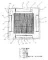
図1及び図2において、天井埋込形の空気調和機の本体1は、内部の中央部付近にファンモーター2とターボファン3とによって構成された送風機4を備え、送風機4を囲むようにして熱交換器5が配設されており、その下部には、熱交換器5を載置すると共に、中央部に吸込口6を有し、外周囲に風路7が形成されたドレンパン8が設けられている。
1 and 2, a main body 1 of a ceiling-embedded air conditioner includes a blower 4 composed of a
空気調和機の本体1の下面には取り外し可能に化粧パネル10が装着されており、その中央部に空気吸込口11(ドレンパン8の吸込口6に対応)が設けられ、空気吸込口11の各辺の外側に矩形状の空気吹出口13(ドレンパン8の風路7に対応)が設けられている。そして、空気吸込口11にはエアフィルタ12が配置され、空気吹出口13には風向ベーン20が回動可能に取り付けられている。
A
空気調和機の本体1(ドレンパン8)への化粧パネル10の取付面には、吸込側と吹出側を分離するためのシール材、言い換えれば、空気吹出口13の周囲をシールするためのシール材22が設けられている。
On the attachment surface of the
シール材22の台座として、各空気吹出口13の長辺外側には長辺外側壁14が設けられ、長辺内側には長辺内側壁15が設けられており、左右の短辺側には左短辺側壁16及び右短辺側壁17が設けられている。そして、長辺外側壁14、左短辺側壁16及び右短辺側壁17の3面は、それぞれ化粧パネル10から分岐して上方に二股状に形成された内側壁と外側壁とを有し、化粧パネルと一体の二重壁構造を形成しており、これらの壁の間に内部を空気層とする断熱空間部(空気断熱層)を設けてシール台座面を形成している。
As a pedestal for the sealing
左短辺側壁16の二重壁構造(右短辺側壁17の二重壁構造についても同様なので、右短辺側壁17側については説明を省略)について、図3を用いて説明すると、左短辺側壁16は、化粧パネル10から分岐して上方に二股状に形成された内側壁16aと外側壁16bとによって化粧パネル10と一体の二重壁構造に形成されており、これらの壁16a、16bの間に内部を空気層とする断熱空間部(空気断熱層)18が設けられてシール台座面を形成している。
The double wall structure of the left short side wall 16 (the same applies to the double wall structure of the right
そして、二重壁構造の左短辺側壁16には、吹出し空気と室内巻き込み空気の流れを偏向する流れ偏向手段を設けてある。すなわち、化粧パネル10と一体に成形された内側壁16aと外側壁16bとからなる二重壁の断熱空間部18の底面18aを、二重壁が設けられた化粧パネル10の意匠下面10aよりも上側に一段高くした状態にして段差部19を形成するようにしてある。
The left
より詳しくは、左短辺側壁16の外側壁16bは、内側壁16aの下部(化粧パネル10の意匠下面10aの高さ位置)のやや上側から空気吹出口13側に分岐して二股状に形成され、外側壁16bと内側壁16aは垂直に立設されて、外側壁16bはドレンパン8内壁の垂直壁8aと同一の垂直面をなすようにしてある。そして、分岐した外側壁16b側の分岐部の底面(断熱空間部の底面)18aが段差部19を形成しており、この段差部19は、空気吹出口13側の角部を湾曲させて湾曲面18bを形成している。
なお、この段差部19は、空気吹出口13側(湾曲面18b側)に向かって断熱空間部の底面18aが上方傾斜(上流側に傾斜)するように形成してもよい。
More specifically, the
In addition, you may form this level | step-
空気吹出口13の左短辺側壁16には二重壁を貫通する支持孔が設けられており、一方、風向ベーン20にはその両側にベーン支持面21aとベーン支持軸21bとが設けられており、ベーン支持軸21bが二重壁の支持孔に回動可能に支持されている。
こうして、左短辺側壁16の外側壁16bに沿って、あるいはベーン支持面21aと左短辺側壁16の外側壁16bとの間の空間部の間を、冷却された吹出し空気30の一部がイ方向に流出するが、吹出し空気30の一部は、空気吹出口13を通過する際に段差部19によって流れが空気吹出口13の外側の斜め下方向のロ方向に広がる。そして、ロ方向に広がった吹出し空気30aは、化粧パネル10の意匠下面10aからハ方向に巻き込まれた室内空気31と空気吹出口13近傍の外側の空間部で合流する。
The left
Thus, a part of the cooled
上記のように、空気吹出口13の長辺外側壁14、左短辺側壁16及び右短辺側壁17はそれぞれ化粧パネル10と一体の二重壁構造を形成しているが、長辺内側にはさらに長辺内側壁15が設けられ、この内側壁15は、その成形上、発泡樹脂成形部材によって構成されており、他のシール台座面と同一高さのシール台座面をなしてシール材22が貼り付けられている。
As described above, the long side
こうして、空気吹出口13は、長辺外側壁14と左右短辺側壁16、17の3面が断熱空間部を有する二重壁によって構成され、長辺内側壁15が発泡樹脂成形部材によって構成されており、さらに、空気調和機の本体1と化粧パネル10との間には空気吹出口13の輪郭に沿って空気吹出口13を取り囲むようにしてシール材22が設けられており、吸込側と吹出側とを確実に気密分離している。
In this way, the
次に、動作について説明する。
冷房運転時において、送風機4が駆動されると、化粧パネル10の空気吸込口11から空気が吸い込まれる。この空気は、熱交換器5を通過して熱交換され、冷却されて、ドレンパン8の風路7を通り、空気吹出口13からイ方向に吹き出す。
この際、左短辺側壁16及び右短辺側壁17には二重壁による断熱空間部18が形成されて空気断熱層が設けられているので、冷却された空気が吹き出しても、空気吹出口13の内部は温度変化が抑えられる。
Next, the operation will be described.
When the blower 4 is driven during the cooling operation, air is sucked from the
At this time, the left
左右短辺側壁16、17に沿ってイ方向に吹出した空気30は、左右短辺側壁16、17の断熱空間部18の底面18aに段差部19を形成され、空気吹出口13側に湾曲面18bが形成されているので、段差部19の湾曲面18bで流れが左右(外側)の斜め下方向であるロ方向に広がる。そして左右のロ方向に吹出した空気30aは、化粧パネル10の意匠下面10aから巻き込まれた室内空気31と空気吹出口13近傍の空間部、すなわち左右短辺側壁16、17から離れた位置の空間部で合流する。
The
本発明によれば、化粧パネル10の左右短辺側壁16、17に、冷却された吹出し空気30のイ方向への流れの一部を偏向させ、外側の斜め下方向であるロ方向に拡げて吹出し空気30aとする流れ偏向手段を設けたので、ロ方向に流れる吹出し空気30aは化粧パネル10の意匠下面10aから巻き込まれた室内空気31と左右短辺側壁16、17から離れた位置で合流する。このため、空気吹出口13周囲の意匠面(意匠下面10a)の結露を防止することができると共に、結露部への汚れ粒子付着による意匠面(意匠下面10a)の汚れを防止することができる。さらに、左右短辺側壁16、17に断熱空間部18が形成されて空気断熱層が設けられ、空気吹出口13の内外面が断熱されるようにしたので、空気吹出口13内部への結露の発生も防止することができる。
According to the present invention, the left and right
1 空気調和機の本体、4 送風機、5 熱交換器、10 化粧パネル、10a 化粧パネルの意匠下面、11 空気吸込口、13 空気吹出口、14 長辺外側壁、15 長辺内側壁、16、17 左右短辺側壁(一対の短辺側壁)、16a 左短辺側壁の内側壁、16b 左短辺側の外側壁、18 断熱空間部(空気断熱層)、18a 断熱空間部の底面(分岐部の底面)、18b 湾曲面、19 段差部、20 風向ベーン、22 シール材、30、30a 吹出し空気、31 室内空気。 DESCRIPTION OF SYMBOLS 1 Main body of air conditioner, 4 air blower, 5 heat exchanger, 10 decorative panel, 10a Design lower surface of decorative panel, 11 air inlet, 13 air outlet, 14 long side outer wall, 15 long side inner wall, 16, 17 left and right short side walls (a pair of short side walls), 16a inner wall of the left short side wall, 16b outer wall on the left short side, 18 heat insulating space (air heat insulating layer), 18a bottom surface of the heat insulating space (branch) Bottom surface), 18b curved surface, 19 stepped portion, 20 wind direction vane, 22 sealing material, 30, 30a blown air, 31 indoor air.
Claims (4)
前記空気吹出口が矩形状に形成され、該空気吹出口の長手方向の両側に対向して前記化粧パネルと一体に短辺側壁が設けられ、
該短辺側壁は、内側壁と、前記化粧パネルの下面より上方において前記内側壁から空気吹出口側に分岐する外側壁とによってこれらの間に断熱空間部を有する二股状の二層構造壁に形成され、
前記外側壁は、前記ドレンパンの前記風路を形成する垂直壁と同一の垂直面をなすように構成され、
前記短辺側壁には、前記空気吹出口から吹き出した空気と室内巻き込み空気との流れを該空気吹出口の長手方向の外側の斜め下方向に向かわせる流れ偏向手段を、前記外側壁の前記垂直面に連続させて設け、
前記流れ偏向手段は、前記短辺側壁の前記空気吹出口側の側面に、該短辺側壁が設けられた前記化粧パネルの下面よりも上方に段あげして設けた段差部によって形成し、
該段差部は、前記内側壁から前記外側壁が分岐する前記二股状の前記二層構造壁の分岐部の底面によって形成されていることを特徴とする天井埋込形空気調和機。 A decorative panel having an air inlet and an air outlet is detachably mounted on a lower surface of an air conditioner body including a blower, a heat exchanger, and a drain pan, and the drain pan mounts the heat exchanger. A ceiling-embedded air conditioner having a suction port corresponding to the air suction port in the center, and having an air passage corresponding to the air outlet in the outer periphery,
The air outlet is formed in a rectangular shape, and a short side wall is provided integrally with the decorative panel so as to face both sides in the longitudinal direction of the air outlet,
The short side wall is a bifurcated two-layer structure wall having a heat insulating space between the inner wall and an outer wall that branches from the inner wall to the air outlet side above the lower surface of the decorative panel. Formed,
The outer wall is configured to form the same vertical plane as the vertical wall that forms the air path of the drain pan,
The short side wall is provided with flow deflecting means for directing the flow of the air blown out from the air outlet and the indoor entrapped air in a diagonally downward direction outside the longitudinal direction of the air outlet. Provided continuously on the surface ,
The flow deflecting means is formed by a stepped portion provided on a side surface of the short side wall on the air outlet side above the lower surface of the decorative panel provided with the short side wall,
The stepped portion is formed by a bottom surface of a branch portion of the bifurcated two-layer structure wall where the outer wall branches from the inner side wall .
Priority Applications (1)
| Application Number | Priority Date | Filing Date | Title |
|---|---|---|---|
| JP2009271798A JP5430371B2 (en) | 2009-11-30 | 2009-11-30 | Recessed ceiling air conditioner |
Applications Claiming Priority (1)
| Application Number | Priority Date | Filing Date | Title |
|---|---|---|---|
| JP2009271798A JP5430371B2 (en) | 2009-11-30 | 2009-11-30 | Recessed ceiling air conditioner |
Publications (3)
| Publication Number | Publication Date |
|---|---|
| JP2011112336A JP2011112336A (en) | 2011-06-09 |
| JP2011112336A5 JP2011112336A5 (en) | 2011-08-25 |
| JP5430371B2 true JP5430371B2 (en) | 2014-02-26 |
Family
ID=44234805
Family Applications (1)
| Application Number | Title | Priority Date | Filing Date |
|---|---|---|---|
| JP2009271798A Expired - Fee Related JP5430371B2 (en) | 2009-11-30 | 2009-11-30 | Recessed ceiling air conditioner |
Country Status (1)
| Country | Link |
|---|---|
| JP (1) | JP5430371B2 (en) |
Families Citing this family (3)
| Publication number | Priority date | Publication date | Assignee | Title |
|---|---|---|---|---|
| CN102980288B (en) * | 2012-12-24 | 2017-11-03 | 应鸿 | Wall-hanging air conditioner indoor unit dust cover |
| JP6195391B2 (en) * | 2014-01-24 | 2017-09-13 | 東芝キヤリア株式会社 | Air conditioner |
| JP7424266B2 (en) * | 2020-09-30 | 2024-01-30 | 株式会社富士通ゼネラル | Ceiling-mounted air conditioner |
Family Cites Families (5)
| Publication number | Priority date | Publication date | Assignee | Title |
|---|---|---|---|---|
| JPH0718898Y2 (en) * | 1989-06-06 | 1995-05-01 | 株式会社東芝 | Air conditioner |
| JP3118543B2 (en) * | 1994-08-22 | 2000-12-18 | ダイキン工業株式会社 | Air conditioner makeup panel |
| JP3408983B2 (en) * | 1999-01-25 | 2003-05-19 | 三菱電機株式会社 | Ceiling-mounted air conditioner |
| JP4107333B2 (en) * | 2006-04-19 | 2008-06-25 | ダイキン工業株式会社 | Ceiling-mounted air conditioner |
| JP2009186075A (en) * | 2008-02-05 | 2009-08-20 | Daikin Ind Ltd | Air-conditioning indoor unit |
-
2009
- 2009-11-30 JP JP2009271798A patent/JP5430371B2/en not_active Expired - Fee Related
Also Published As
| Publication number | Publication date |
|---|---|
| JP2011112336A (en) | 2011-06-09 |
Similar Documents
| Publication | Publication Date | Title |
|---|---|---|
| JP5923871B2 (en) | Indoor unit for air conditioner | |
| JP4544364B1 (en) | Air conditioner | |
| JP2013148237A (en) | Air conditioner | |
| JP5430371B2 (en) | Recessed ceiling air conditioner | |
| JP6139669B2 (en) | Air conditioner | |
| JP2011237092A (en) | Floor setting type indoor unit for air conditioner | |
| JP6048818B2 (en) | Outdoor unit | |
| JP6439537B2 (en) | Embedded ceiling air conditioner | |
| WO2017033241A1 (en) | Indoor unit of air conditioner | |
| JP2008095972A (en) | Indoor unit of air conditioner | |
| JP6097931B2 (en) | Heat exchange ventilator | |
| WO2015155855A1 (en) | Air conditioner | |
| JP5860752B2 (en) | Air conditioner | |
| JP3900950B2 (en) | Decorative panel for ceiling cassette type air conditioner | |
| JP6451516B2 (en) | Embedded ceiling air conditioner | |
| JP2015068561A (en) | Indoor unit for air conditioner | |
| JP2011112336A5 (en) | ||
| JP3972811B2 (en) | Air conditioner | |
| WO2015104791A1 (en) | Air-conditioning device | |
| JP2014005976A (en) | Indoor unit of air conditioner | |
| JP2010169277A (en) | Ceiling-embedded air conditioner | |
| EP3073207B1 (en) | Ceiling-embedded air conditioner | |
| JP6451445B2 (en) | Embedded ceiling air conditioner | |
| JP6153141B2 (en) | Air conditioner | |
| JP6375837B2 (en) | Embedded ceiling air conditioner |
Legal Events
| Date | Code | Title | Description |
|---|---|---|---|
| A521 | Request for written amendment filed |
Free format text: JAPANESE INTERMEDIATE CODE: A523 Effective date: 20110711 |
|
| A621 | Written request for application examination |
Free format text: JAPANESE INTERMEDIATE CODE: A621 Effective date: 20110711 |
|
| A977 | Report on retrieval |
Free format text: JAPANESE INTERMEDIATE CODE: A971007 Effective date: 20121128 |
|
| A131 | Notification of reasons for refusal |
Free format text: JAPANESE INTERMEDIATE CODE: A131 Effective date: 20121204 |
|
| A521 | Request for written amendment filed |
Free format text: JAPANESE INTERMEDIATE CODE: A523 Effective date: 20130201 |
|
| A131 | Notification of reasons for refusal |
Free format text: JAPANESE INTERMEDIATE CODE: A131 Effective date: 20130604 |
|
| A521 | Request for written amendment filed |
Free format text: JAPANESE INTERMEDIATE CODE: A523 Effective date: 20130731 |
|
| TRDD | Decision of grant or rejection written | ||
| A01 | Written decision to grant a patent or to grant a registration (utility model) |
Free format text: JAPANESE INTERMEDIATE CODE: A01 Effective date: 20131105 |
|
| A61 | First payment of annual fees (during grant procedure) |
Free format text: JAPANESE INTERMEDIATE CODE: A61 Effective date: 20131203 |
|
| R150 | Certificate of patent or registration of utility model |
Free format text: JAPANESE INTERMEDIATE CODE: R150 Ref document number: 5430371 Country of ref document: JP Free format text: JAPANESE INTERMEDIATE CODE: R150 |
|
| R250 | Receipt of annual fees |
Free format text: JAPANESE INTERMEDIATE CODE: R250 |
|
| R250 | Receipt of annual fees |
Free format text: JAPANESE INTERMEDIATE CODE: R250 |
|
| R250 | Receipt of annual fees |
Free format text: JAPANESE INTERMEDIATE CODE: R250 |
|
| R250 | Receipt of annual fees |
Free format text: JAPANESE INTERMEDIATE CODE: R250 |
|
| R250 | Receipt of annual fees |
Free format text: JAPANESE INTERMEDIATE CODE: R250 |
|
| R250 | Receipt of annual fees |
Free format text: JAPANESE INTERMEDIATE CODE: R250 |
|
| R250 | Receipt of annual fees |
Free format text: JAPANESE INTERMEDIATE CODE: R250 |
|
| LAPS | Cancellation because of no payment of annual fees |