JP5430158B2 - Sheet conveying apparatus, sheet processing apparatus, and image forming apparatus - Google Patents

Sheet conveying apparatus, sheet processing apparatus, and image forming apparatus Download PDF

Info

Publication number
JP5430158B2
JP5430158B2 JP2009015900A JP2009015900A JP5430158B2 JP 5430158 B2 JP5430158 B2 JP 5430158B2 JP 2009015900 A JP2009015900 A JP 2009015900A JP 2009015900 A JP2009015900 A JP 2009015900A JP 5430158 B2 JP5430158 B2 JP 5430158B2
Authority
JP
Japan
Prior art keywords
sheet
conveyed
conveying
path
conveyance
Prior art date
Legal status (The legal status is an assumption and is not a legal conclusion. Google has not performed a legal analysis and makes no representation as to the accuracy of the status listed.)
Active
Application number
JP2009015900A
Other languages
Japanese (ja)
Other versions
JP2010173758A (en
JP2010173758A5 (en
Inventor
俊行 岩田
Current Assignee (The listed assignees may be inaccurate. Google has not performed a legal analysis and makes no representation or warranty as to the accuracy of the list.)
Canon Inc
Original Assignee
Canon Inc
Priority date (The priority date is an assumption and is not a legal conclusion. Google has not performed a legal analysis and makes no representation as to the accuracy of the date listed.)
Filing date
Publication date
Application filed by Canon Inc filed Critical Canon Inc
Priority to JP2009015900A priority Critical patent/JP5430158B2/en
Publication of JP2010173758A publication Critical patent/JP2010173758A/en
Publication of JP2010173758A5 publication Critical patent/JP2010173758A5/ja
Application granted granted Critical
Publication of JP5430158B2 publication Critical patent/JP5430158B2/en
Active legal-status Critical Current
Anticipated expiration legal-status Critical

Links

Images

Landscapes

  • Separation, Sorting, Adjustment, Or Bending Of Sheets To Be Conveyed (AREA)
  • Feeding Of Articles By Means Other Than Belts Or Rollers (AREA)

Description

本発明は、例えば、ステイプルジョブ(複数のシートを綴じる)等の処理を行う際、処理中にシートを重ね合わせ、シート束を形成して搬送するシート搬送装置と、このようなシート搬送装置を備えたシート処理装置及び画像形成装置とに関する。特に、シート搬送装置でシートの除電を行う構造に関する。   The present invention provides, for example, a sheet conveying apparatus that stacks sheets during processing and forms a sheet bundle and conveys the sheet when performing processing such as a staple job (binding a plurality of sheets), and such a sheet conveying apparatus. The present invention relates to a sheet processing apparatus and an image forming apparatus provided. In particular, the present invention relates to a structure in which a sheet is neutralized by a sheet conveying apparatus.

従来、複写機やプリンタ等の画像形成装置において、画像形成装置本体にフィニッシャ等のシート処理装置を設け、複数のシートを、束ねて排出する処理や、綴じる処理等の様々な処理を施すことが可能な構造が知られている。また、このような処理の作業中に、画像形成装置からのシートの排出を止めることがないようにする構造も知られている。例えば、シート処理装置の途中でシートを待機させ、次のシートと重ね合わせてシート束を形成し、シート束を搬送するようにした構造が知られている(例えば、特許文献1参照)。   2. Description of the Related Art Conventionally, in an image forming apparatus such as a copying machine or a printer, a sheet processing apparatus such as a finisher is provided in the image forming apparatus main body, and various processes such as a process of binding a plurality of sheets together and discharging them are performed. Possible structures are known. Also known is a structure that prevents the discharge of the sheet from the image forming apparatus from being stopped during such processing. For example, a structure is known in which a sheet is waited in the middle of a sheet processing apparatus, a sheet bundle is formed by overlapping with the next sheet, and the sheet bundle is conveyed (see, for example, Patent Document 1).

特開2005−104676号公報Japanese Patent Laying-Open No. 2005-104676

ところで、表面をコーティングしたシートや、坪量(一定面積あたりのシートの重さ)の軽いシートを使用する場合、低温、低湿の環境においては、シートが帯電し易い(シートに静電気が発生し易い)。この場合、上述のような、シート束を搬送する構造において、シート同士が貼り付いた状態で、シートの整合処理等を行う処理部に搬送される可能性がある。この場合には、処理部においてシートを整合させることができなかったり、既積載のシートを次のシートが押し出してしまい、積載不良を引き起こす恐れがある。   By the way, when using a sheet coated on the surface or a sheet having a low basis weight (sheet weight per fixed area), the sheet is easily charged in a low temperature and low humidity environment (static electricity is easily generated on the sheet). ). In this case, in the structure for conveying a sheet bundle as described above, the sheets may be conveyed to a processing unit that performs sheet alignment processing or the like in a state where the sheets are adhered to each other. In this case, the processing unit cannot align the sheets, or the next sheet may be pushed out from the already stacked sheets, which may cause a stacking failure.

この点について、図13に示す構造を用いて説明する。シート処理装置1は、ステイプル等の処理中に、画像形成装置からのシートの排出を止める事のないように、シートを重ね合わせてシート束とし、シート束の搬送を行うシート搬送装置2を備えている。シート搬送装置2は、シートを搬送する搬送路3と、搬送路3から分岐する分岐路4と、搬送路3に搬送されたシートを分岐路4に向けて反転させる(スイッチバックさせる)反転手段5とを備える。   This point will be described using the structure shown in FIG. The sheet processing apparatus 1 includes a sheet conveying apparatus 2 that superimposes sheets into a sheet bundle and conveys the sheet bundle so that the discharge of the sheet from the image forming apparatus is not stopped during processing such as stapling. ing. The sheet conveyance device 2 includes a conveyance path 3 that conveys a sheet, a branch path 4 that branches from the conveyance path 3, and a reversing unit that reverses (switches back) the sheet conveyed to the conveyance path 3 toward the branch path 4. 5.

このうちの分岐路4は、シートの搬送方向を正逆切替可能な正逆転ローラ6と、1対の搬送ガイド7、8により構成され、正逆転ローラ6により搬送されたシートを、両搬送ガイド7、8により下方へ導く。なお、図13の右側に配置された搬送ガイド8は、下方部分を折り曲げ、シートが搬送された場合にシートの先端と当接して、シートを適切な位置に導くようにしている。   The branch path 4 is composed of a forward / reverse roller 6 capable of switching between the forward and reverse directions of the sheet and a pair of transport guides 7 and 8. 7 and 8 lead downward. The conveyance guide 8 arranged on the right side of FIG. 13 bends the lower part and abuts against the leading edge of the sheet when the sheet is conveyed to guide the sheet to an appropriate position.

シート束を形成する場合には、シート搬送装置2に先行して搬送された先行シートを分岐路4に、反転手段5及び正逆転ローラ6により搬送する。そして、分岐路4で先行シートを待機させた状態で、シート搬送装置2に後続シートを搬送する。次いで、後続シートの搬送のタイミングと合わせて、先行シートを分岐路4から正逆転ローラ6により反転させ、搬送路3で先行シートと後続シートとを合流させ、重ね合わせる。その後、重ね合わせたシート束をステイプル等の処理を行う処理部9に搬送する。   When forming a sheet bundle, the preceding sheet conveyed prior to the sheet conveying apparatus 2 is conveyed to the branch path 4 by the reversing means 5 and the forward / reverse rotation roller 6. The succeeding sheet is conveyed to the sheet conveying apparatus 2 in a state where the preceding sheet is made to wait on the branch path 4. Next, in synchronization with the conveyance timing of the subsequent sheet, the preceding sheet is reversed from the branch path 4 by the forward / reverse rotation roller 6, and the preceding sheet and the subsequent sheet are merged in the conveyance path 3 and overlapped. Thereafter, the overlapped sheet bundle is conveyed to a processing unit 9 that performs processing such as stapling.

このようにシート束を搬送する場合、シートが帯電していると、先行シートと後続シートとを重ね合わせる際に、シート同士が大きくずれた状態で貼り付く可能性がある。そして、この状態で処理部9に搬送されても、処理部9でシートの整合を十分に行えなかったり、既積載のシートを次のシートが押し出してしまう等して、シートの積載不良等を引き起こす可能性がある。   When the sheet bundle is conveyed in this way, when the sheets are charged, there is a possibility that the sheets are stuck in a state of being largely displaced when the preceding sheet and the succeeding sheet are overlapped. Even if the sheet is conveyed to the processing unit 9 in this state, the sheet cannot be sufficiently aligned in the processing unit 9, or the next sheet is pushed out from the already stacked sheet. May cause.

このようなシートの貼り付きを防止するために、例えば、搬送路の途中に除電手段を設け、シートの除電を行うことが考えられる。例えば、両端にシートを搬送する1対のローラ対が配置された搬送路の途中に、除電手段を設けることが考えられる。但し、このような構造の場合、シートの除電を十分に行えない可能性がある。   In order to prevent such sticking of the sheet, for example, it is conceivable to provide a charge removing unit in the middle of the conveying path to remove the sheet. For example, it is conceivable to provide a static elimination means in the middle of a conveyance path in which a pair of rollers for conveying a sheet at both ends is arranged. However, in such a structure, there is a possibility that the sheet cannot be sufficiently neutralized.

即ち、除電手段として、例えば、導電性の除電布や除電ブラシをシートの表面に接触させたり、近接させる等の構造が考えられる。この場合に、例えばシートがローラ対に引き込まれる際に撓む等して、シートの表面と除電手段との間に隙間が生じたり、又は、隙間が大きくなり過ぎる可能性がある。この結果、シートの除電を十分に行えない。   That is, as the charge removal means, for example, a structure in which a conductive charge removal cloth or a charge removal brush is brought into contact with or close to the surface of the sheet can be considered. In this case, there is a possibility that a gap is generated between the surface of the sheet and the static elimination means or the gap becomes too large due to, for example, bending when the sheet is drawn into the roller pair. As a result, the sheet cannot be sufficiently discharged.

そこで、本発明は、このような現状に鑑みてなされたものであり、シートの除電を効果的に行えるシート搬送装置、シート処理装置及び画像形成装置を提供することを目的とするものである。   SUMMARY An advantage of some aspects of the invention is that it provides a sheet conveying apparatus, a sheet processing apparatus, and an image forming apparatus that can effectively remove a sheet.

本発明は、シートを搬送する搬送路を備えたシート搬送装置において、前記搬送路から分岐する分岐路と、前記分岐路の下流に開放された開放空間と、前記搬送路から前記分岐路に搬送されたシートの搬送方向を正逆切替可能で、シートを前記開放空間に垂下保持可能な正逆搬送手段と、前記開放空間に垂下されたシートに接触又は近接することにより、シートに発生した静電気を除去する除電手段と、を備え、前記搬送路に搬送される先行シートを前記分岐路に受け入れ、前記正逆搬送手段により前記開放空間に垂下された前記先行シートを前記除電手段にて除電した後、前記先行シートに続いて搬送される後続シートを前記分岐路に受け入れ、前記先行シートと前記後続シートを重ねるシート搬送装置において、前記除電手段は、前記先行シートの上に重ねられた前記後続シートを除電することができるように、前記先行シートからみて、前記後続シートが重ねられた側に配置されていることを特徴とするものである。 The present invention provides a sheet conveying apparatus including a conveying path for conveying a sheet, a branch path branched from the conveyance path, an open space opened downstream of the branch path, and a conveyance path from the conveyance path to the branch path. The forward / reverse switching of the transported direction of the sheet is possible, the forward / reverse transport means capable of hanging the sheet in the open space, and the static electricity generated in the sheet by contacting or approaching the sheet suspended in the open space. And a charge removing unit that removes the preceding sheet that is conveyed to the conveyance path into the branch path, and the charge removal unit removes the preceding sheet that is suspended in the open space by the forward / reverse conveyance unit. Thereafter, in the sheet conveying apparatus that receives the succeeding sheet conveyed subsequent to the preceding sheet in the branch path, and overlaps the preceding sheet and the succeeding sheet, the charge eliminating unit includes the leading sheet As can be neutralizes the subsequent sheets stacked on a sheet, it said preceding sheet viewed, is characterized in that it is arranged on the subsequent sheet are stacked side.

本発明によれば、シートを開放空間に垂下された状態で除電を行えるため、シートが撓むことがなく、シートと除電手段との当接関係、又は、シートと除電手段との隙間を一定にでき、シートの除電を効果的に行える。また、シートの除電は、シートを分岐路に待機させているときに行っているため、効率的である。   According to the present invention, since the static elimination can be performed in a state where the sheet is suspended in the open space, the sheet does not bend, and the contact relationship between the sheet and the static elimination means or the gap between the sheet and the static elimination means is constant. The sheet can be effectively neutralized. Further, since the charge removal of the sheet is performed while the sheet is waiting on the branch path, it is efficient.

以下、本発明の第1の実施の形態について図1ないし図10を用いて説明する。なお、説明中で取り上げている数値は、参考数値であって、本発明を限定するものではない。また、同一の符号を付したものは、同様な構成であり、これらについての重複説明は、適宜に省略するものとする。   A first embodiment of the present invention will be described below with reference to FIGS. In addition, the numerical value taken up in description is a reference numerical value, Comprising: This invention is not limited. Moreover, what attached | subjected the same code | symbol is the same structure, The duplication description about these shall be abbreviate | omitted suitably.

先ず、全体構成である白黒又はカラーの複写機等の画像形成装置100について、図1を用いて説明する。画像形成装置100は、画像形成装置本体(以下、単に「装置本体」という)101と、シート処理装置であるフィニッシャ102とを備えている。装置本体101内には、それぞれがシートを収納する為の複数のシート収納部103、103と、シートの表面に画像を形成するための画像形成部104とを備える。   First, an image forming apparatus 100 such as a black-and-white or color copying machine having an overall configuration will be described with reference to FIG. The image forming apparatus 100 includes an image forming apparatus main body (hereinafter simply referred to as “apparatus main body”) 101 and a finisher 102 that is a sheet processing apparatus. The apparatus main body 101 includes a plurality of sheet storage units 103 and 103 for storing sheets, and an image forming unit 104 for forming an image on the surface of the sheet.

このうちの画像形成部104は、それぞれ画像形成手段としてのイエロー、マゼンタ、シアン、ブラックの感光ドラム105aないし105dや、シートにトナー像を定着させる為の定着器106等を備える。シート収納部103から供給されたシートは、イメージリーダ107からの画像や、画像入力装置からのデータに基いて、例えば、感光ドラム105aないし105dによって、表面に4色のトナー像が転写され、定着器106に搬送される。そして、定着器106により表面にトナー画像を定着したシートは、装置本体101から外に排出される。なお、画像形成部104の構造及び作用は、従来から知られている構造と同様である為、詳しい説明は省略する。また、画像形成部104は、図示の例に限らず、従来から知られている他の構造であっても良い。   Among these, the image forming unit 104 includes yellow, magenta, cyan, and black photosensitive drums 105a to 105d as image forming units, a fixing device 106 for fixing a toner image on a sheet, and the like. The sheet supplied from the sheet storage unit 103 is transferred with a four-color toner image on the surface by, for example, the photosensitive drums 105a to 105d based on the image from the image reader 107 and the data from the image input device. It is conveyed to the vessel 106. Then, the sheet on which the toner image is fixed on the surface by the fixing device 106 is discharged out of the apparatus main body 101. Since the structure and operation of the image forming unit 104 are the same as those conventionally known, detailed description thereof is omitted. Further, the image forming unit 104 is not limited to the illustrated example, and may have another structure conventionally known.

フィニッシャ102は、装置本体101に接続されて、装置本体101から排出されたシートを順に取り込み、取り込んだ複数のシートを整合してステイプル等の処理を施す。なお、フィニッシャ102の制御部は、装置本体101の制御部等のネットワークに繋がっており、装置本体101から排出されたシートは、フィニッシャ102でオンラインにより処理することができるようになっている。また、フィニッシャ102は、オプションとして使用されることがあるため、装置本体101は、フィニッシャ102と切り離して、単独でも使用できるようになっている。勿論、フィニッシャ102と装置本体101とが一体であっても良い。この場合、フィニッシャ102の制御部を装置本体101の制御部と一体的に設け、装置本体101からフィニッシャ102を直接制御するようにしてもよい。   The finisher 102 is connected to the apparatus main body 101, sequentially takes sheets discharged from the apparatus main body 101, aligns the plurality of taken-in sheets, and performs processing such as stapling. The control unit of the finisher 102 is connected to a network such as a control unit of the apparatus main body 101, and sheets discharged from the apparatus main body 101 can be processed online by the finisher 102. Further, since the finisher 102 may be used as an option, the apparatus main body 101 can be used separately from the finisher 102. Of course, the finisher 102 and the apparatus main body 101 may be integrated. In this case, the control unit of the finisher 102 may be provided integrally with the control unit of the apparatus main body 101 so that the finisher 102 is directly controlled from the apparatus main body 101.

このようなフィニッシャ102は、図2に示すように、入口ローラ対108、横レジ検知ユニット109、シフトユニット110、シート搬送装置200、処理部300等を備える。装置本体101から排出されたシートは、入口ローラ対108によりフィニッシャ102の内部に導かれる。入口ローラ対108の下流には、シートのスラスト方向の端部を検知する横レジ検知ユニット109、及び、シートをシート搬送方向と直交する方向に移動させるシフトユニット110とを配置している。そして、横レジ検知ユニット109によりシートのスラスト方向の端部を検知し、その検知結果に基づいて、必要に応じて、シフトユニット110により、シートを所定量シート搬送方向と直交する方向へ移動させ、シートの仕分け等を行う。   As shown in FIG. 2, the finisher 102 includes a pair of entrance rollers 108, a lateral registration detection unit 109, a shift unit 110, a sheet conveying device 200, a processing unit 300, and the like. The sheet discharged from the apparatus main body 101 is guided into the finisher 102 by the inlet roller pair 108. Downstream of the entrance roller pair 108, a lateral registration detection unit 109 that detects an end of the sheet in the thrust direction, and a shift unit 110 that moves the sheet in a direction orthogonal to the sheet conveyance direction are arranged. Then, the lateral registration detection unit 109 detects the end of the sheet in the thrust direction, and based on the detection result, the shift unit 110 moves the sheet by a predetermined amount in a direction orthogonal to the sheet conveyance direction as necessary. Sorting sheets, etc.

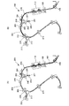
シフトユニット110の下流には、シート搬送装置200が設けられている。シート搬送装置200は、搬送ローラ対201、搬送路202、第1バッファローラ対203、分岐路204、切替手段205、第2バッファローラ対206、開放空間207、除電手段208等を備える。シフトユニット110から搬送されたシートは、搬送ローラ対201により搬送路202に搬送され、更に、搬送路202に設けた、反転手段である第1バッファローラ対203に向けて搬送される。第1バッファローラ対203は、正逆転可能である。   A sheet conveying device 200 is provided downstream of the shift unit 110. The sheet conveying apparatus 200 includes a conveying roller pair 201, a conveying path 202, a first buffer roller pair 203, a branch path 204, a switching unit 205, a second buffer roller pair 206, an open space 207, a charge removing unit 208, and the like. The sheet conveyed from the shift unit 110 is conveyed to the conveyance path 202 by the conveyance roller pair 201 and further conveyed toward the first buffer roller pair 203 that is provided in the conveyance path 202 and is a reversing unit. The first buffer roller pair 203 can be rotated forward and backward.

第1バッファローラ対203により所定位置まで搬送されたシートは、一端停止し、第1バッファローラ対203を逆転させるスイッチバック制御によって、シートを反転してシート搬送方向と反対の方向へ搬送する。そして、シートを、搬送路202の途中から下方に分岐した分岐路204に向けて搬送する。この際、搬送路202と分岐路204との分岐部209に設けた切替手段205を下方に傾斜させることにより、シートの搬送方向を分岐路204の方向に切り替える。なお、切替手段205は、シートを搬送ローラ対201から第1バッファローラ対203に向けて搬送する際には、図2に示す位置として、シートの搬送方向を第1バッファローラ対203の方向とする。   The sheet conveyed to a predetermined position by the first buffer roller pair 203 stops once, and is reversed and conveyed in the direction opposite to the sheet conveying direction by switchback control that reversely rotates the first buffer roller pair 203. Then, the sheet is conveyed toward the branch path 204 branched downward from the middle of the conveyance path 202. At this time, the sheet conveying direction is switched to the direction of the branch path 204 by inclining a switching unit 205 provided in a branching unit 209 between the conveyance path 202 and the branch path 204 downward. When the sheet is transported from the transport roller pair 201 toward the first buffer roller pair 203, the switching unit 205 sets the transport direction of the sheet to the direction of the first buffer roller pair 203 as the position shown in FIG. To do.

切替手段205により搬送方向を切り替えられたシートは、分岐路204に受け入れられ、分岐路204の途中に配置された、正逆切替可能な正逆搬送手段である第2バッファローラ対206に搬送される。そして、第2バッファローラ対206により分岐路204内に引き込まれる。第2バッファローラ対206も、第1バッファローラ対203と同様に、正逆転可能で、シートの搬送方向を正逆に切り替え可能である。   The sheet whose conveyance direction has been switched by the switching unit 205 is received by the branch path 204 and is conveyed to the second buffer roller pair 206 which is arranged in the middle of the branch path 204 and is a normal / reverse conveyance unit capable of forward / reverse switching. The Then, the second buffer roller pair 206 is drawn into the branch path 204. Similarly to the first buffer roller pair 203, the second buffer roller pair 206 can be rotated forward and backward, and the sheet conveying direction can be switched between forward and reverse.

第2バッファローラ対206により分岐路204内に搬送されたシートは、分岐路204の下方に開放された開放空間207に向けて搬送され、シートの一部が開放空間207に垂下される。即ち、分岐路204は、1対の搬送ガイド210、211により構成され、両搬送ガイド210、211のシート反転搬送方向下流は、開放空間207に開放されている。従って、両搬送ガイド210、211の下流から突出したシートの一部は、開放空間207に垂下された状態となる。第2バッファローラ対206は、シートを所定量、開放空間207に搬送した後で停止する。この状態で、シートの反転搬送方向後端側が第2バッファローラ対206に挟まれたままシートの搬送が停止し、シートの反転搬送方向前端部ないし中間部が開放空間207に垂下されたままとなる。即ち、第2バッファローラ対206は、シートを開放空間207に垂下保持可能である。なお、開放空間207は、シートサイズに拘らず、シートを所定量搬送し、垂下された状態で、シートが何れの部分にも接触しない程度の空間を有する。 The sheet conveyed into the branch path 204 by the second buffer roller pair 206 is transported toward the open space 207 opened below the branch path 204, and a part of the sheet is suspended in the open space 207. That is, the branch path 204 is configured by a pair of conveyance guides 210 and 211, and the downstream of the conveyance guides 210 and 211 in the sheet reverse conveyance direction is opened to an open space 207. Accordingly, a part of the sheet protruding from the downstream side of the both conveyance guides 210 and 211 is suspended from the open space 207. The second buffer roller pair 206 stops after conveying a predetermined amount of sheets to the open space 207. In this state, the conveyance of the sheet is stopped while the rear end side in the reverse conveyance direction of the sheet is sandwiched between the second buffer roller pair 206, and the front end portion or the intermediate portion in the reverse conveyance direction of the sheet is suspended in the open space 207. Become. That is, the second buffer roller pair 206 can hold the sheet in the open space 207. Note that the open space 207 has such a space that the sheet is not in contact with any portion in a state where the sheet is conveyed and hung down regardless of the sheet size.

開放空間207には、導電性の除電布や除電ブラシ、導電板等の除電手段208が設けられている。除電手段208は、開放空間207に垂下されたシートに接触又は近接する位置に設けられている。従って、シートを開放空間207に垂下するように搬送している間に、除電手段208がシートに接触又は近接し、シートに発生した静電気が、除電手段208にて除去される。なお、シートを開放空間207に垂下される量は、シートに発生した静電気をほぼ除去できるだけ、シートを除電手段208に接触又は近接させられる程度とする。   The open space 207 is provided with a static elimination means 208 such as a conductive static elimination cloth, a static elimination brush, or a conductive plate. The static eliminating unit 208 is provided at a position in contact with or close to the sheet suspended in the open space 207. Accordingly, while the sheet is transported so as to hang down in the open space 207, the static elimination means 208 contacts or approaches the sheet, and static electricity generated on the sheet is removed by the static elimination means 208. It should be noted that the amount that the sheet is suspended in the open space 207 is such that the sheet can be brought into contact with or brought close to the charge removal means 208 so that static electricity generated in the sheet can be substantially removed.

上述のように、第2バッファローラ対206は、シートを開放空間207に垂下された状態で停止し、シートを一時待機させる。そして、搬送路202に後続して搬送されるシートが分岐部209を通過するタイミングと合わせて、第2バッファローラ対206を逆転し(第2バッファローラ対206によりシートの搬送方向を切替え)、シートを搬送路202に戻すように制御される。これにより、シートを搬送路202で重ね合わせてシート束を形成する。搬送路202は、所定の間隔を有する搬送ガイド対により構成され、複数のシートを重ね合わせて搬送可能である。シートを重ね合わせる枚数は、ユーザが選択したジョブに応じて、例えば、2枚重ねて搬送する場合と、3枚重ねて搬送する場合がある。シートを重ね合わせる枚数は、任意に設定可能である。なお、シートの重ね合わせ動作の詳細は後述する。   As described above, the second buffer roller pair 206 stops in a state where the sheet is suspended in the open space 207, and temporarily holds the sheet. Then, the second buffer roller pair 206 is reversely rotated at the timing when the sheet conveyed following the conveyance path 202 passes through the branching portion 209 (the sheet conveyance direction is switched by the second buffer roller pair 206). Control is performed to return the sheet to the conveyance path 202. As a result, the sheets are stacked on the conveyance path 202 to form a sheet bundle. The conveyance path 202 includes a pair of conveyance guides having a predetermined interval, and can convey a plurality of sheets by overlapping them. Depending on the job selected by the user, for example, two sheets may be stacked and the sheets may be stacked and transferred in three sheets. The number of sheets to be superimposed can be arbitrarily set. Details of the sheet overlapping operation will be described later.

なお、シート束を形成しない場合には、第1バッファローラ対203に搬送されたシートを、第1バッファローラ対203の下流に配置された別の切替手段212により、排出ローラ対213に向けて搬送方向を切り替える。そして、排出ローラ対213により排出トレイ214に排出する。または、別の切替手段212により中間搬送ローラ対215に向けて搬送方向を切り替え、排出正逆ローラ対301により積載トレイ302にそのまま排出されるか、次述する綴じ処理を施す為に、処理トレイ303に積載される。   When a sheet bundle is not formed, the sheet conveyed to the first buffer roller pair 203 is directed toward the discharge roller pair 213 by another switching unit 212 disposed downstream of the first buffer roller pair 203. Switch the transport direction. Then, the paper is discharged to the discharge tray 214 by the discharge roller pair 213. Alternatively, the conveyance direction is switched toward the intermediate conveyance roller pair 215 by another switching unit 212 and the sheet is discharged as it is to the stacking tray 302 by the discharge forward / reverse roller pair 301 or the processing tray for performing the binding process described below. 303 is loaded.

また、上述の説明では、シートをスイッチバックさせて分岐路204に搬送しているが、例えば、シートの搬送方向の先後端を入れ替えず、そのまま搬送路202から分岐路204に搬送しても良い。この場合、搬送路202から分岐路204に分岐する部分の角度を緩やかにする等して、シートの搬送方向先端から分岐路204にシートを受け入れ易くする。この場合、1枚のシートを除電した後、そのまま搬送路202に戻して搬送するか、搬送路202に後続して搬送されたシートと2枚重ねて搬送するかの何れかの搬送が可能である。   In the above description, the sheet is switched back and conveyed to the branch path 204. However, for example, the front and rear ends of the sheet in the conveyance direction may not be replaced, and may be conveyed from the conveyance path 202 to the branch path 204 as it is. . In this case, by making the angle of the portion branched from the conveyance path 202 to the branch path 204 gentle, the sheet can be easily received into the branch path 204 from the front end in the sheet conveyance direction. In this case, after discharging one sheet, the sheet can be returned to the conveyance path 202 as it is, or can be conveyed by overlapping the sheet conveyed following the conveyance path 202. is there.

何れにしても、シート搬送装置200により形成されたシート束は、第1バッファローラ対203から別の切替手段212により中間搬送ローラ対215を介して処理部300に搬送され、処理部300を構成する処理トレイ303に積載される。この際、排出正逆ローラ対301によりシート束を排出側に引き込み、排出正逆ローラ対301を逆転することにより、シート束を処理トレイ303に積載する。   In any case, the sheet bundle formed by the sheet conveying apparatus 200 is conveyed from the first buffer roller pair 203 to the processing unit 300 via another intermediate conveying roller pair 215 by another switching unit 212, thereby configuring the processing unit 300. To the processing tray 303 to be loaded. At this time, the sheet bundle is pulled to the discharge side by the discharge forward / reverse roller pair 301, and the sheet bundle is stacked on the processing tray 303 by reversing the discharge forward / reverse roller pair 301.

処理部300は、処理トレイ303に積載されたシートを、整合して1つの束に束ねる処理(整合する処理)、束ねたシート束の後端(シート搬送方向の上流端)をステイプラ304で綴じるステイプル処理等を行う。なお、ステイプラ304は、シート束の角部や背部に相当する部分を綴じるようになっている。処理部300で行える他の処理としては、取り込んだシートの後端付近に孔を開ける穿孔処理、ソート処理、ノンソート処理、シート束を折る折処理、製本処理等の各種の処理がある。処理部300で上述のような処理が施されたシート束は、排出正逆ローラ対301を再度、正転させることにより積載トレイ302に排出、積載される。   The processing unit 300 aligns and stacks the sheets stacked on the processing tray 303 into one bundle (alignment processing), and binds the rear end (upstream end in the sheet conveying direction) of the bundled sheet bundle with the stapler 304. Perform stapling. The stapler 304 is configured to bind portions corresponding to corners and back portions of the sheet bundle. As other processes that can be performed by the processing unit 300, there are various processes such as a punching process in which holes are formed in the vicinity of the rear end of the fetched sheet, a sorting process, a non-sorting process, a folding process for folding a sheet bundle, and a bookbinding process. The sheet bundle that has been subjected to the processing as described above in the processing unit 300 is discharged and stacked on the stacking tray 302 by rotating the discharging forward / reverse roller pair 301 again in the forward direction.

次に、シート搬送装置200の詳しい構造について、図2で説明していない部分を中心に、図3を用いて説明する。シート搬送装置200は、シフトユニット110の下流側に搬送ガイド対216を配置し、搬送ガイド対216により、シフトユニット110から搬送されたシートを、搬送ガイド対216の下流に設けた搬送ローラ対201に案内する。搬送ローラ対201は、モータ217により駆動される。即ち、モータ217の駆動力がタイミングベルト218を介してプーリ219に伝達され、プーリ219に固定された搬送ローラ対201が駆動する。   Next, a detailed structure of the sheet conveying apparatus 200 will be described with reference to FIG. 3 with a focus on portions not described in FIG. In the sheet conveying apparatus 200, a conveyance guide pair 216 is disposed on the downstream side of the shift unit 110, and a sheet conveyed from the shift unit 110 by the conveyance guide pair 216 is conveyed to a conveyance roller pair 201 provided on the downstream side of the conveyance guide pair 216. To guide. The conveyance roller pair 201 is driven by a motor 217. That is, the driving force of the motor 217 is transmitted to the pulley 219 via the timing belt 218, and the conveying roller pair 201 fixed to the pulley 219 is driven.

搬送ローラ対201の下流には、搬送路202を構成するバッファ搬送ガイド対220を配置し、シートを第1バッファローラ対203に案内する。第1バッファローラ対203は、第2バッファローラ対206及び中間搬送ローラ対215と共に、モータ221により駆動される。即ち、それぞれのローラ対203、206、215に固定されたプーリ223ないし225に掛け渡されたタイミングベルト222を介して、モータ221の駆動力を同期して、各ローラ対203、206、215に伝達している。また、モータ221は、正逆両方向に回転駆動が可能であるため、各ローラ対203、206、215は、同期して正逆両方向に回転する。   A buffer conveyance guide pair 220 constituting the conveyance path 202 is arranged downstream of the conveyance roller pair 201 to guide the sheet to the first buffer roller pair 203. The first buffer roller pair 203 is driven by the motor 221 together with the second buffer roller pair 206 and the intermediate transport roller pair 215. In other words, the driving force of the motor 221 is synchronized with each roller pair 203, 206, and 215 via a timing belt 222 that is wound around pulleys 223 to 225 fixed to the respective roller pairs 203, 206, and 215. Communicating. Further, since the motor 221 can be driven to rotate in both forward and reverse directions, the roller pairs 203, 206, and 215 rotate in both forward and reverse directions in synchronization.

このように、各ローラ対203、206、215を、モータ221により同期して駆動することにより、シート束形成時のモータの起動のばらつき等をなくし、シート束形成時のシートの位置を正確に制御できるようにしている。   In this way, each roller pair 203, 206, and 215 is driven synchronously by the motor 221, thereby eliminating variations in the starting of the motor at the time of forming the sheet bundle and accurately positioning the sheet at the time of forming the sheet bundle. I can control it.

なお、排出ローラ対213は、図示しないモータにより駆動される。また、中間搬送ローラ対215は、前述したように、シートを処理部300に向けて搬送するが、本実施の形態の場合には、第1バッファローラ対203と同期して、シートを反転させる機能も有する。従って、中間搬送ローラ対215は、シートサイズが大きい場合には、第1バッファローラ対203と共に、シートを分岐部209に向けて反転させる反転手段を構成する。   The discharge roller pair 213 is driven by a motor (not shown). Further, as described above, the intermediate conveyance roller pair 215 conveys the sheet toward the processing unit 300. In the present embodiment, the sheet is reversed in synchronization with the first buffer roller pair 203. It also has a function. Therefore, the intermediate conveyance roller pair 215 constitutes a reversing unit that reverses the sheet toward the branching unit 209 together with the first buffer roller pair 203 when the sheet size is large.

切替手段205及び別の切替手段212は、ソレノイド226a、226bを使用して切替動作を行う。切替手段205、212は、切替板部227a、227bのソレノイド226a、226bと反対側部分に、それぞれ切替軸228a、228bを有し、各切替軸228a、228bには、バネ掛け支板229a、229bが取り付けられている。各バネ掛け支板229a、229bと図示しない固定の部分との間には、バネ230a、230bが掛け渡されており、各バネ掛け支板229a、229bに、図3の反時計方向に向けて付勢している。従って、各バネ掛け支板229a、229bを取り付けた各切替手段205、212も、同方向に付勢されている。   The switching unit 205 and the other switching unit 212 perform switching operation using the solenoids 226a and 226b. The switching means 205 and 212 have switching shafts 228a and 228b on the opposite sides of the switching plates 227a and 227b from the solenoids 226a and 226b, respectively. Is attached. Spring 230a, 230b is spanned between each spring hanging support plate 229a, 229b and a fixed portion (not shown), and each spring hanging support plate 229a, 229b is directed counterclockwise in FIG. Energized. Accordingly, the switching means 205 and 212 to which the spring hanging support plates 229a and 229b are attached are also urged in the same direction.

また、各切替手段205、212と各ソレノイド226a、226bとの間で、搬送路202から外れる部分に、ソレノイドバネ231a、231bを掛け渡している。そして、各ソレノイド226a、226bの駆動(ON)により、各ソレノイドバネ231a、231bを介して各切替手段205、212を、図3の矢印の方向にそれぞれ引っ張り可能としている。一方、ソレノイド226a、226bをOFFにすると、各バネ230a、230bの弾力に基づいて、各切替手段205、212が図3に示す位置に復帰する。このように、各切替手段205、212を駆動し、切替板部227a、227bを傾斜させることにより、シートの搬送方向を切り替えている。尚、別の切替手段212は、通常は図3に示す位置にあり、シートを排出トレイ214に排出する時のみ、矢印の方向へ移動する。   In addition, solenoid springs 231a and 231b are bridged between portions of the switching units 205 and 212 and the solenoids 226a and 226b at portions that are separated from the conveyance path 202. Then, by driving (ON) each solenoid 226a, 226b, each switching means 205, 212 can be pulled in the direction of the arrow in FIG. 3 via each solenoid spring 231a, 231b. On the other hand, when the solenoids 226a and 226b are turned off, the switching means 205 and 212 return to the positions shown in FIG. 3 based on the elasticity of the springs 230a and 230b. In this way, the sheet conveying direction is switched by driving the switching units 205 and 212 and tilting the switching plates 227a and 227b. The other switching means 212 is normally located at the position shown in FIG. 3 and moves in the direction of the arrow only when the sheet is discharged to the discharge tray 214.

除電手段208は、例えば、導電性の板材等を折り曲げ形成した固定部材232の先端部に、導電性の布やブラシ、板等の導電部材233を固定してなる。固定部材232の基端部は、搬送ガイド210に固定され、固定部材232の先端部を、分岐路204の開口部に近接した位置に配置している。そして、この先端部に固定された導電部材233を分岐路204から垂下されるシートと接触または近接させるようにしている。なお、固定部材232には、図示しないアース用のリード線が接続される。   The static elimination means 208 is formed by, for example, fixing a conductive member 233 such as a conductive cloth, a brush, or a plate to the tip of a fixing member 232 formed by bending a conductive plate material or the like. The base end portion of the fixing member 232 is fixed to the conveyance guide 210, and the distal end portion of the fixing member 232 is disposed at a position close to the opening of the branch path 204. Then, the conductive member 233 fixed to the leading end is brought into contact with or close to the sheet suspended from the branch path 204. The fixing member 232 is connected to a ground lead wire (not shown).

次に、本実施の形態のシート搬送装置200のシート束形成動作について図4ないし図7を用いて説明する。   Next, a sheet bundle forming operation of the sheet conveying apparatus 200 according to the present embodiment will be described with reference to FIGS.

先ず、図4(A)に示すように、装置本体101から排出され、フィニッシャ102に先行して搬送された先行シート400が、入口ローラ対108を通過し、シフトユニット110へ搬送される。そして、図4(B)に示すように、先行シート400が、搬送ローラ対201から、第1バッファローラ対203へ搬送される。この際、切替手段205は、図4(A)、(B)に示すように、同図の上側に位置する。   First, as shown in FIG. 4A, the preceding sheet 400 discharged from the apparatus main body 101 and conveyed prior to the finisher 102 passes through the inlet roller pair 108 and is conveyed to the shift unit 110. Then, as shown in FIG. 4B, the preceding sheet 400 is conveyed from the conveying roller pair 201 to the first buffer roller pair 203. At this time, as shown in FIGS. 4A and 4B, the switching unit 205 is positioned on the upper side of the figure.

その後、図5(A)に示すように、先行シート400が、中間搬送ローラ対215へ搬送される。この際、別の切替手段212は、図5(A)に示すように、同図の左側に位置する。また、先行シート400は、第1バッファローラ対203と中間搬送ローラ対215とにより搬送されている。そして、第1バッファローラ対203の下流側に配置されたバッファパスセンサ234がONしてから、ユーザが、例えば、図1の操作部111で入力したシートサイズに応じた量、先行シート400を搬送したところで、先行シート400の搬送が停止される。即ち、バッファパスセンサ234が先行シート400の先端を検知した後、シートサイズに応じた量、先行シート400を搬送した状態で、第1バッファローラ対203と中間搬送ローラ対215とを停止する。なお、シートサイズが小さい場合には、シートが中間搬送ローラ対215に到達しない場合もある。   Thereafter, as shown in FIG. 5A, the preceding sheet 400 is conveyed to the intermediate conveyance roller pair 215. At this time, another switching means 212 is located on the left side of the figure as shown in FIG. The preceding sheet 400 is conveyed by the first buffer roller pair 203 and the intermediate conveyance roller pair 215. Then, after the buffer path sensor 234 arranged on the downstream side of the first buffer roller pair 203 is turned ON, the user can, for example, change the preceding sheet 400 by an amount corresponding to the sheet size input by the operation unit 111 of FIG. When the sheet is conveyed, the conveyance of the preceding sheet 400 is stopped. That is, after the buffer path sensor 234 detects the leading edge of the preceding sheet 400, the first buffer roller pair 203 and the intermediate conveying roller pair 215 are stopped while the preceding sheet 400 is conveyed by an amount corresponding to the sheet size. If the sheet size is small, the sheet may not reach the intermediate conveyance roller pair 215.

上述のように先行シート400が停止するのと同時に、切替手段205は、図5(B)に示すように、同図の下側に移動する。そして、例えば、先行シート400の搬送停止から30ms後に、図3に示したモータ221が逆方向に回転駆動し、第1バッファローラ対203及び中間搬送ローラ対215が逆転する。これにより、スイッチバックが開始され、先行シート400が、シート搬送方向と反対の方向へ搬送される。反転搬送された先行シート400は、図5(B)に示すように、第2バッファローラ対206及び分岐路204を介して開放空間207に垂下される。この時、第2バッファローラ対206も、モータ221により、第1バッファローラ対203及び中間搬送ローラ対215と同方向に、同期して回転する。   At the same time as the preceding sheet 400 stops as described above, the switching unit 205 moves to the lower side of the drawing as shown in FIG. For example, 30 ms after the conveyance of the preceding sheet 400 is stopped, the motor 221 shown in FIG. 3 is rotated in the reverse direction, and the first buffer roller pair 203 and the intermediate conveyance roller pair 215 are reversed. As a result, switchback is started, and the preceding sheet 400 is conveyed in a direction opposite to the sheet conveying direction. As shown in FIG. 5B, the preceding sheet 400 conveyed in the reverse direction is suspended in the open space 207 through the second buffer roller pair 206 and the branch path 204. At this time, the second buffer roller pair 206 is also rotated in synchronization with the first buffer roller pair 203 and the intermediate transport roller pair 215 by the motor 221.

開放空間207に垂下された先行シート400は、除電手段208にて除電される。そして、バッファパスセンサ234がOFFしてから、例えば、先行シート400を20mm搬送したところで、再び搬送を停止する。即ち、バッファパスセンサ234が先行シート400の反転搬送方向後端を検知した後、先行シート400を20mm、反転搬送方向に搬送した状態で、第2バッファローラ対206を停止する。この状態で、先行シート400は、第2バッファローラ対206に挟まれた状態で、開放空間207に垂れ下がっている。そして、フィニッシャ102に後続して搬送される後続シート401と重ね合わせるために、先行シート400が待機する。   The preceding sheet 400 suspended in the open space 207 is neutralized by the neutralizing means 208. Then, after the buffer path sensor 234 is turned OFF, for example, when the preceding sheet 400 is conveyed 20 mm, the conveyance is stopped again. That is, after the buffer path sensor 234 detects the trailing edge of the preceding sheet 400 in the reverse conveying direction, the second buffer roller pair 206 is stopped while the preceding sheet 400 is conveyed in the reverse conveying direction by 20 mm. In this state, the preceding sheet 400 hangs down in the open space 207 while being sandwiched between the second buffer roller pair 206. Then, the preceding sheet 400 stands by in order to overlap the succeeding sheet 401 conveyed subsequent to the finisher 102.

後続シート401は、先行シート400のスイッチバックと同時に、シート搬送装置200へ搬送され、搬送センサ235がONしてから(後続シート401の先端を検知してから)、所定距離搬送したところで、モータ221が再び正転側に駆動する。そして、第1、第2バッファローラ対203、206及び中間搬送ローラ対215が、同期して正転側に駆動し、図6(A)に示すように、先行シート400と後続シート401とが、重ね合わされ(シート束が形成され)た状態で搬送される。この時、先行シート400と後続シート401とは、シート搬送方向に関し所定量ずらした状態で重ねられている。   The succeeding sheet 401 is transported to the sheet transport apparatus 200 simultaneously with the switchback of the preceding sheet 400, and after the transport sensor 235 is turned on (after detecting the leading edge of the succeeding sheet 401), the motor is moved to a predetermined distance. 221 is again driven to the forward rotation side. Then, the first and second buffer roller pairs 203 and 206 and the intermediate conveyance roller pair 215 are synchronously driven to the normal rotation side, and as shown in FIG. Then, the sheet is conveyed in a state of being overlaid (sheet bundle is formed). At this time, the preceding sheet 400 and the succeeding sheet 401 are overlapped with a predetermined amount shifted in the sheet conveying direction.

前述した場合と同様、バッファパスセンサ234がONした後、所定量シート束を搬送したところで、シート束の搬送が停止され、シート束停止から30ms後にスイッチバックが開始される。そして、図6(B)に示すように、バッファパスセンサ234がOFFしてから20mm搬送したところで、シート束が停止し、後後続シート402が搬送されるまで待機する。   Similarly to the case described above, after the buffer path sensor 234 is turned ON, when a predetermined amount of the sheet bundle is conveyed, the conveyance of the sheet bundle is stopped, and the switchback is started 30 ms after the sheet bundle is stopped. Then, as shown in FIG. 6B, when the buffer path sensor 234 is turned off and conveyed 20 mm, the sheet bundle is stopped, and the process waits until the subsequent subsequent sheet 402 is conveyed.

また、前述した場合と同様に、シート束のスイッチバックと同時に、後後続シート402がシート搬送装置200へ搬送される。そして、搬送センサ235がONした後、所定距離搬送したところで、図3のモータ221が駆動し、図7(A)に示すように、3枚重ねた状態でシート400、401、402が搬送される。そして、3枚重ねられシート束となった各シート400、401、402は、図7(B)に示すように、シート搬送装置200の下流へ搬送され、必要に応じて、図2のステイプラ304で綴じらた後、または、綴じ処理をせずに、積載トレイ302へ排出される。尚、上述の説明では、3枚のシートを重ねているが、ユーザが選択したジョブ枚数に応じて、2枚のシートを重ねた状態で、シート搬送装置200の下流へと搬送する場合もある。   Similarly to the case described above, the succeeding subsequent sheet 402 is conveyed to the sheet conveying apparatus 200 simultaneously with the switchback of the sheet bundle. Then, after the conveyance sensor 235 is turned on, when the sheet is conveyed for a predetermined distance, the motor 221 shown in FIG. 3 is driven, and the sheets 400, 401, and 402 are conveyed in a state where three sheets are stacked as shown in FIG. The Then, as shown in FIG. 7B, the three sheets 400, 401, and 402 that are stacked to form a bundle of three sheets are conveyed downstream of the sheet conveying apparatus 200, and if necessary, the stapler 304 in FIG. After the binding is performed, the sheet is discharged to the stacking tray 302 without performing the binding process. In the above description, three sheets are stacked. However, depending on the number of jobs selected by the user, there are cases where two sheets are stacked and conveyed downstream of the sheet conveying apparatus 200. .

次に、本実施形態の画像形成装置100の制御について、図8に示すブロック図により説明する。CPU回路部500は、CPU501を有し、ROM502に格納されているプログラム及び操作部111の設定に従って、次述する各制御部に指令する。これら各制御部は、原稿給紙装置制御部503、イメージリーダ制御部504、画像信号制御部505、プリンタ制御部506、フィニッシャ制御部507、外部インターフェイス508等である。このうちの原稿給紙装置制御部503は原稿給紙装置を、イメージリーダ制御部504はイメージリーダを、プリンタ制御部506はプリンタを、フィニッシャ制御部507はフィニッシャを、それぞれ制御する。本実施の形態において、フィニッシャ制御部507をフィニッシャ102に搭載した構成について説明するが、フィニッシャ制御部507を装置本体101側のCPU回路部500に一体的に設け、装置本体101側から直接フィニッシャ102を制御してもよい。   Next, control of the image forming apparatus 100 of the present embodiment will be described with reference to the block diagram shown in FIG. The CPU circuit unit 500 includes a CPU 501, and instructs each control unit described below according to the program stored in the ROM 502 and the setting of the operation unit 111. These control units are a document feeder control unit 503, an image reader control unit 504, an image signal control unit 505, a printer control unit 506, a finisher control unit 507, an external interface 508, and the like. The document feeder control unit 503 controls the document feeder, the image reader controller 504 controls the image reader, the printer controller 506 controls the printer, and the finisher controller 507 controls the finisher. In the present embodiment, a configuration in which the finisher control unit 507 is mounted on the finisher 102 will be described. However, the finisher control unit 507 is integrally provided in the CPU circuit unit 500 on the apparatus main body 101 side, and the finisher 102 directly from the apparatus main body 101 side. May be controlled.

また、RAM509は、制御データを一時的に保持する領域や、制御に伴う演算の作業領域として用いられる。外部インターフェイス508は、コンピューター510からのインターフェイスであり、プリントデータを画像に展開して画像信号制御部505へ出力する。イメージリーダ制御部504から画像信号制御部505へは、イメージリーダで読み取られた画像が出力され、画像信号制御部505からプリンタ制御部506へ出力された画像は露光制御部へ入力される。   The RAM 509 is used as an area for temporarily storing control data and a work area for calculations associated with control. An external interface 508 is an interface from the computer 510 and develops print data into an image and outputs the image to the image signal control unit 505. The image read by the image reader is output from the image reader control unit 504 to the image signal control unit 505, and the image output from the image signal control unit 505 to the printer control unit 506 is input to the exposure control unit.

続いて、フィニッシャ制御部507のブロック図について説明する。フィニッシャ制御部507は、CPU600、RAM601、ROM602、I/O603、ネットワークインターフェイス604、通信インターフェイス605等で構成されている。このうちのI/O603は、シート束形成部制御部606を司り、搬送センサ235、バッファパスセンサ234のON/OFFのタイミングから得られた情報を基に、モータ217、221、ソレノイド226a、226bの起動タイミングを制御している。   Next, a block diagram of the finisher control unit 507 will be described. The finisher control unit 507 includes a CPU 600, a RAM 601, a ROM 602, an I / O 603, a network interface 604, a communication interface 605, and the like. Among these, the I / O 603 controls the sheet bundle forming unit control unit 606, and based on information obtained from the ON / OFF timing of the conveyance sensor 235 and the buffer path sensor 234, the motors 217 and 221 and the solenoids 226a and 226b. The start timing is controlled.

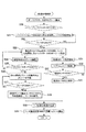
次に、図9、10に示すフローチャートを用いて、本実施の形態のシート束形成動作の流れについて説明する。なお、このうちの図9は、2枚のシート束を形成する場合を、図10は、3枚のシート束を形成する場合をそれぞれ示している。   Next, the flow of the sheet bundle forming operation of the present embodiment will be described using the flowcharts shown in FIGS. Of these, FIG. 9 shows a case where two sheet bundles are formed, and FIG. 10 shows a case where three sheet bundles are formed.

先ず、図9に示すように、シート搬送が開始されると(S1)、シートがシフトユニット110を通過する(S2)。次いで、シートが搬送され、搬送センサ235がONした後(S3)、シートが、搬送ローラ対201により搬送され(S4)、第1バッファローラ対203に到達する。更に、第1バッファローラ対203がシートを搬送し(S5)、バッファパスセンサ234がONして(S6)、所定量搬送したところで、モータ221が停止し、シートの搬送が停止する(S7)。シートの搬送停止と同時に、ソレノイド226aがONし、切替手段205が図5(B)の位置へと移動する(S8)。そして、シートの搬送停止から、例えば30ms後にモータ221が逆転し、スイッチバックが開始され、シートが反転し、第2バッファローラ対206へ搬送される(S9)。   First, as shown in FIG. 9, when sheet conveyance is started (S1), the sheet passes through the shift unit 110 (S2). Next, after the sheet is conveyed and the conveyance sensor 235 is turned on (S3), the sheet is conveyed by the conveyance roller pair 201 (S4) and reaches the first buffer roller pair 203. Further, the first buffer roller pair 203 conveys the sheet (S5), the buffer path sensor 234 is turned on (S6), and when the predetermined amount is conveyed, the motor 221 stops and the sheet conveyance stops (S7). . Simultaneously with the conveyance of the sheet, the solenoid 226a is turned on, and the switching means 205 moves to the position shown in FIG. 5B (S8). Then, for example, after 30 ms from the stop of the conveyance of the sheet, the motor 221 reverses, the switchback is started, the sheet is reversed, and is conveyed to the second buffer roller pair 206 (S9).

第2バッファローラ対206を抜けて開放空間207に搬送されたシートは、除電手段208で除電され(S10)、バッファパスセンサ234がOFFしてから(S11)、例えば20mm搬送したところで停止し、次のシートを待機する(S12)。シートのスイッチバックが終了すると、ソレノイド226aがOFFし、切替手段205が図6(A)の位置へ移動し、次のシートを搬送できるようにする(S13)。これと同時に2枚目のシートの搬送が開始され(S15)、2枚目のシートが、シフトユニット110を通過する(S16)。次いで、2枚目のシートが搬送され、搬送センサ235がONした後(S17)、2枚目のシートが、更に搬送ローラ対201へと搬送される(S18)。   The sheet conveyed through the second buffer roller pair 206 and conveyed to the open space 207 is neutralized by the neutralizing means 208 (S10), and after the buffer path sensor 234 is turned off (S11), for example, when the sheet is conveyed 20 mm, the sheet stops. Wait for the next sheet (S12). When the switchback of the sheet is completed, the solenoid 226a is turned off, and the switching unit 205 moves to the position shown in FIG. 6A so that the next sheet can be conveyed (S13). Simultaneously, the conveyance of the second sheet is started (S15), and the second sheet passes through the shift unit 110 (S16). Next, after the second sheet is conveyed and the conveyance sensor 235 is turned on (S17), the second sheet is further conveyed to the conveyance roller pair 201 (S18).

S17で搬送センサ235がONしてから、2枚目のシートを所定量搬送したところで、モータ221が起動し、1枚目のシートが再び搬送される(S14)。そして、1枚目のシートと2枚目のシートが合流し(S19)、2枚のシート束が、第1バッファローラ対203へ搬される。シート束を2枚とする場合には、シート束は、そのままシート搬送装置200の下流へ搬送される。   After the conveyance sensor 235 is turned on in S17, when the second sheet is conveyed by a predetermined amount, the motor 221 is activated and the first sheet is conveyed again (S14). Then, the first sheet and the second sheet merge (S 19), and the two sheet bundles are carried to the first buffer roller pair 203. When two sheet bundles are used, the sheet bundle is conveyed downstream of the sheet conveying apparatus 200 as it is.

一方、シート束を3枚とする場合には、図10に示すステップに移行する。第1バッファローラ対203により搬送されたシートは、バッファパスセンサ234がON(S20)してから、2枚のシート束を所定量搬送したところで、シート束の搬送を停止する(S21)。シート束の搬送停止と同時に、1枚目と2枚目を重ねる場合と同様に、ソレノイド226aがONする(S22)。そして、シート束の搬送停止から、例えば30ms後にモータ221が再び逆転し、スイッチバックが開始され、シート束が第2バッファローラ対206へ搬送される(S23)。   On the other hand, when the number of sheet bundles is three, the process proceeds to the step shown in FIG. The sheet conveyed by the first buffer roller pair 203 is stopped when the two sheet bundles are conveyed by a predetermined amount after the buffer path sensor 234 is turned on (S20) (S21). Simultaneously with the conveyance stop of the sheet bundle, the solenoid 226a is turned on (S22), as in the case where the first and second sheets are stacked. Then, for example, after 30 ms from the stop of the conveyance of the sheet bundle, the motor 221 reverses again, the switchback is started, and the sheet bundle is conveyed to the second buffer roller pair 206 (S23).

第2バッファローラ対206を抜けて開放空間207に搬送されたシート束は、除電手段208で除電され(S24)、バッファパスセンサ234がOFFしてから(S25)、例えば20mm搬送したところで停止し、3枚目のシートを待機する(S26)。シート束のスイッチバックが完了すると、ソレノイド226aがOFFする(S27)。これと同時に、3枚目のシートの搬送が開始され(S29)、3枚目のシートが、シフトユニット110を通過する(S30)。次いで、3枚目のシートが搬送され、搬送センサ235がONした後(S31)、3枚目のシートが、更に搬送ローラ対201へ搬送される(S32)。   The sheet bundle that has passed through the second buffer roller pair 206 and is conveyed to the open space 207 is neutralized by the neutralizing means 208 (S24), and after the buffer path sensor 234 is turned off (S25), for example, the sheet bundle stops when conveyed 20 mm. Wait for the third sheet (S26). When the switchback of the sheet bundle is completed, the solenoid 226a is turned off (S27). At the same time, conveyance of the third sheet is started (S29), and the third sheet passes through the shift unit 110 (S30). Next, after the third sheet is conveyed and the conveyance sensor 235 is turned on (S31), the third sheet is further conveyed to the conveyance roller pair 201 (S32).

3枚目のシートの搬送により、搬送センサ235がONしてから、所定量搬送したところでモータ221が再び起動し、2枚のシート束の搬送が開始される(S28)。そして、2枚のシート束と3枚目のシートが合流し(S33)、3枚のシート束が、シート搬送装置200の下流へ搬送される(S34)。   When the conveyance sensor 235 is turned on by the conveyance of the third sheet, the motor 221 is started again when a predetermined amount is conveyed, and conveyance of the two sheet bundles is started (S28). Then, the two sheet bundles and the third sheet are merged (S33), and the three sheet bundles are conveyed downstream of the sheet conveying apparatus 200 (S34).

上述した本実施の形態によれば、シート又はシート束(シート等)を開放空間207に垂下された状態で除電を行えるため、シート等が撓むことがない。従って、シート等と除電手段208との当接関係、又は、シート等と除電手段208との隙間を一定にでき、シート等の除電を効果的に行える。また、シート等の除電は、シートを分岐路204に待機させているときに行っているため、効率的である。更に、シートの除電効果を上げる事ができる為、シートの帯電による整合、積載の乱れを防ぎ、積載トレイ302上でのシートの積載性を向上させる事ができる。 According to the above-described embodiment, since the charge removal can be performed while the sheet or the sheet bundle (sheet or the like) is suspended in the open space 207, the sheet or the like is not bent. Therefore, the contact relationship between the sheet or the like and the charge removal means 208 or the gap between the sheet or the like and the charge removal means 208 can be made constant, and the sheet or the like can be discharged efficiently. Moreover, since the charge removal of the sheet or the like is performed while the sheet is waiting in the branch path 204, it is efficient. Further, since the sheet neutralization effect can be increased, alignment and stacking disturbance due to sheet charging can be prevented, and the stackability of sheets on the stacking tray 302 can be improved.

<第2の実施の形態>
本発明の第2の実施の形態について、図11を用いて説明する。本実施の形態の場合には、除電手段208aを、上述の第1の実施の形態に対し、分岐路204の開口部を挟んで反対側に設けている。即ち、除電手段208aを構成する固定部材232を、図11の右側の搬送ガイド211に固定している。このように構成される本実施の形態の場合、シート束を形成した場合の2枚目以降のシートに対しても、除電手段208aを構成する導電部材233が、直接、接触又は近接するため、2枚目以降のシートの除電をより効率良く行える。除電手段208aの構造及び作用は、設置場所以外は第1の実施の形態の除電手段208と同様である。その他の構造及び作用は、上述の第1の実施の形態と同様である。
<Second Embodiment>
A second embodiment of the present invention will be described with reference to FIG. In the case of the present embodiment, the static elimination means 208a is provided on the opposite side of the first embodiment with the opening of the branch path 204 interposed therebetween. That is, the fixing member 232 constituting the static eliminating unit 208a is fixed to the conveyance guide 211 on the right side in FIG. In the case of this embodiment configured as described above, the conductive member 233 constituting the static elimination means 208a is also in direct contact with or close to the second and subsequent sheets when the sheet bundle is formed. The neutralization of the second and subsequent sheets can be performed more efficiently. The structure and operation of the static elimination means 208a are the same as those of the static elimination means 208 of the first embodiment except for the installation location. Other structures and operations are the same as those in the first embodiment.

<第3の実施の形態>
本発明の第3の実施の形態について、図12を用いて説明する。本実施の形態の場合には、分岐路204の開口部を挟んで両側に、それぞれ除電手段208、208aを配置している。また、除電手段208、208a同士は、互いに、シート搬送方向に関しずれた位置に配置される。図示の例の場合、左側の搬送ガイド210に固定された除電手段208の導電部材233が、分岐路204の開口部寄りに配置されている。これに対して、右側の搬送ガイド211に固定された除電手段208aの導電部材233は、除電手段208の導電部材233よりも、分岐路204からシート搬送方向に関し離れた位置に配置されている。なお、除電手段208、208aのシート搬送方向に関する位置関係は、図示の例と逆であっても良い。
<Third Embodiment>
A third embodiment of the present invention will be described with reference to FIG. In the case of the present embodiment, static elimination means 208 and 208a are arranged on both sides of the opening of the branch path 204, respectively. Further, the static eliminating units 208 and 208a are arranged at positions shifted from each other in the sheet conveying direction. In the case of the illustrated example, the conductive member 233 of the static elimination means 208 fixed to the left conveyance guide 210 is disposed near the opening of the branch path 204. On the other hand, the conductive member 233 of the static elimination unit 208 a fixed to the right conveyance guide 211 is disposed at a position farther from the branch path 204 in the sheet conveyance direction than the conductive member 233 of the static elimination unit 208. In addition, the positional relationship regarding the sheet conveyance direction of the static eliminating units 208 and 208a may be opposite to the illustrated example.

このように構成される本実施の形態の場合、除電手段208、208aを、シート搬送方向に関しずらして配置している為、シートの除電をより効率良く行える。また、シート束の除電を行う場合でも、シート束の表裏方向両側に除電手段208、208aが配置されるため、シート束の除電もより効率良く行える。例えば、除電手段208が1枚目のシートに接触又は近接し、除電手段208aが2枚目又は3枚目のシートに接触又は近接する。その他の構造及び作用は、上述の第1の実施の形態又は第2の実施の形態と同様である。   In the case of the present embodiment configured as described above, since the static elimination means 208 and 208a are arranged so as to be shifted with respect to the sheet conveying direction, the static elimination of the sheet can be performed more efficiently. Further, even when the sheet bundle is neutralized, the neutralization means 208 and 208a are arranged on both sides of the sheet bundle in the front and back direction, so that the sheet bundle can be neutralized more efficiently. For example, the static elimination means 208 contacts or approaches the first sheet, and the static elimination means 208a contacts or approaches the second or third sheet. Other structures and operations are the same as those in the first embodiment or the second embodiment described above.

上述した各実施の形態において、シート搬送装置200をフィニッシャ102に一体的に組み込んだ構成について説明したが、これに限らない。例えば、シート搬送装置200を、別装置として設けてもよいし、画像形成装置本体101に一体に組み込んでも、本発明は有効である。   In each of the above-described embodiments, the configuration in which the sheet conveying apparatus 200 is integrated into the finisher 102 has been described. However, the configuration is not limited thereto. For example, the present invention is effective even if the sheet conveying apparatus 200 may be provided as a separate apparatus or integrated into the image forming apparatus main body 101.

第1の実施の形態に係る画像形成装置の概略構成を示す図。1 is a diagram illustrating a schematic configuration of an image forming apparatus according to a first embodiment. 第1の実施の形態に係るシート処理装置の概略構成を示す図。1 is a diagram illustrating a schematic configuration of a sheet processing apparatus according to a first embodiment. 第1の実施の形態に係るシート搬送装置の概略構成を示す図。FIG. 2 is a diagram illustrating a schematic configuration of a sheet conveying apparatus according to the first embodiment. 第1の実施の形態に係るシート束形成の第1、2工程を説明するための、シート搬送装置の概略構成を示す図。The figure which shows schematic structure of the sheet conveying apparatus for demonstrating the 1st, 2nd process of sheet | seat bundle formation which concerns on 1st Embodiment. 同じく第3、4工程を説明するためのシート搬送装置の概略構成を示す図。The figure which shows schematic structure of the sheet conveying apparatus for demonstrating the 3rd, 4th process similarly. 同じく第5、6工程を説明するためのシート搬送装置の概略構成を示す図。The figure which shows schematic structure of the sheet conveying apparatus for demonstrating a 5th, 6th process similarly. 同じく第7、8工程を説明するためのシート搬送装置の概略構成を示す図。The figure which shows schematic structure of the sheet conveying apparatus for demonstrating a 7th, 8th process similarly. 第1の実施の形態に係る画像形成装置の制御部のブロック図。2 is a block diagram of a control unit of the image forming apparatus according to the first embodiment. FIG. 第1の実施の形態に係る、2枚のシート束形成時のフローチャート。The flowchart at the time of two sheet bundle formation based on 1st Embodiment. 同じく3枚のシート束形成時のフローチャート。The flowchart at the time of the same 3 sheet bundle formation. 第2の実施の形態に係るシート搬送装置の概略構成を示す図。FIG. 4 is a diagram illustrating a schematic configuration of a sheet conveying apparatus according to a second embodiment. 第3の実施の形態に係るシート搬送装置の概略構成を示す図。The figure which shows schematic structure of the sheet conveying apparatus which concerns on 3rd Embodiment. 途中でシートを待機させる構造として考えられるシート処理装置の1例を示す概略構成図。The schematic block diagram which shows an example of the sheet processing apparatus considered as a structure which waits a sheet in the middle.

100 画像形成装置
101 装置本体
102 フィニッシャ
108 入口ローラ対
109 横レジ検知ユニット
110 シフトユニット
200 シート搬送装置
201 搬送ローラ対
202 搬送路
203 第1バッファローラ対
204 分岐路
205 切替手段
206 第2バッファローラ対
207 開放空間
208、208a 除電手段
209 分岐部
210 搬送ガイド
211 搬送ガイド
212 別の切替手段
213 排出ローラ対
214 排出トレイ
215 中間搬送ローラ対
234 バッファパスセンサ
235 搬送センサ
300 処理部
302 積載トレイ
303 処理トレイ
304 ステイプラ
400 先行シート
401 後続シート
402 後後続シート
DESCRIPTION OF SYMBOLS 100 Image forming apparatus 101 Apparatus main body 102 Finisher 108 Inlet roller pair 109 Horizontal registration detection unit 110 Shift unit 200 Sheet conveying apparatus 201 Conveying roller pair 202 Conveying path 203 First buffer roller pair 204 Branching path 205 Switching means 206 Second buffer roller pair 207 Open space 208, 208a Neutralizing unit 209 Branching unit 210 Conveying guide 211 Conveying guide 212 Another switching unit 213 Discharging roller pair 214 Discharging tray 215 Intermediate conveying roller pair 234 Buffer path sensor 235 Conveying sensor 300 Processing unit 302 Stacking tray 303 Processing tray 304 Stapler 400 Preceding sheet 401 Subsequent sheet 402 Subsequent succeeding sheet

Claims (8)

シートを搬送する搬送路を備えたシート搬送装置において、
前記搬送路から分岐する分岐路と、
前記分岐路の下流に開放された開放空間と、
前記搬送路から前記分岐路に搬送されたシートの搬送方向を正逆切替可能で、シートを前記開放空間に垂下保持可能な正逆搬送手段と、
前記開放空間に垂下されたシートに接触又は近接することにより、シートに発生した静電気を除去する除電手段と、を備え、
前記搬送路に搬送される先行シートを前記分岐路に受け入れ、前記正逆搬送手段により前記開放空間に垂下された前記先行シートを前記除電手段にて除電した後、前記先行シートに続いて搬送される後続シートを前記分岐路に受け入れ、前記先行シートと前記後続シートを重ねるシート搬送装置において、
前記除電手段は、前記先行シートの上に重ねられた前記後続シートを除電することができるように、前記先行シートからみて、前記後続シートが重ねられた側に配置されていることを特徴とするシート搬送装置。
In a sheet conveying apparatus having a conveying path for conveying a sheet,
A branch path branched from the transport path;
An open space opened downstream of the branch path;
A forward / reverse conveying means capable of switching forward and reverse the conveyance direction of the sheet conveyed from the conveyance path to the branch path, and capable of holding the sheet hanging down in the open space;
A charge eliminating means for removing static electricity generated in the sheet by contacting or approaching the sheet suspended in the open space,
The preceding sheet conveyed to the conveying path is received in the branch path, and the preceding sheet suspended in the open space by the forward / reverse conveying means is discharged by the discharging means, and then conveyed following the preceding sheet. In the sheet conveying apparatus that receives the succeeding sheet to the branch path and overlaps the preceding sheet and the succeeding sheet,
The neutralizing means is arranged on the side where the succeeding sheet is superimposed as viewed from the preceding sheet, so that the succeeding sheet superimposed on the preceding sheet can be neutralized. Sheet conveying device.
前記搬送路に搬送され、前記搬送路と前記分岐路との分岐部を通過したシートを、反転させる反転手段と、
前記分岐部に配置され、前記搬送路から反転されたシートの搬送方向を、前記分岐路の方向に切り替える切替手段と、を備え、
前記反転手段により反転させたシートを、前記切替手段により前記分岐路に搬送し、前記開放空間に垂下させることを特徴とする、請求項1に記載のシート搬送装置。
The conveyed to the conveying path, the sheet over bets that have passed through the branch portion between the branch path and the transport path, and reversing means for reversing,
Switching means arranged in the branching section and switching the transport direction of the sheet reversed from the transport path to the direction of the branch path,
The sheet conveying apparatus according to claim 1, wherein the sheet reversed by the reversing unit is conveyed to the branch path by the switching unit and suspended in the open space.
前記開放空間に搬送されたシートが垂下された状態では、前記垂下されたシートが何れの部分にも接触しないように、前記開放空間は構成されていることを特徴とする請求項1又は2に記載のシート搬送装置。 The open space is configured so that the suspended sheet does not come into contact with any portion in a state where the sheet conveyed to the open space is suspended. The sheet conveying apparatus according to the description. 前記除電手段は、前記先行シートからみて、前記後続シートが重ねられた側に配置された第1の除電手段と、前記先行シートからみて、前記後続シートが重ねられていない側に配置された第2の除電手段とを有する請求項1ないし3のいずれか1項に記載のシート搬送装置。  The static elimination means includes a first static elimination means arranged on the side where the subsequent sheet is overlapped as viewed from the preceding sheet, and a first neutralization means arranged on the side where the subsequent sheet is not overlapped as seen from the preceding sheet. The sheet conveying apparatus according to any one of claims 1 to 3, further comprising two neutralizing units. 前記第1の除電手段と前記第2の除電手段とは、シートの搬送方向において、ずれた位置に配置されていることを特徴とする請求項4に記載のシート搬送装置。  5. The sheet conveying apparatus according to claim 4, wherein the first charge eliminating unit and the second charge eliminating unit are arranged at positions shifted in the sheet conveying direction. シートに画像を形成する画像形成部と、請求項1ないし5のいずれか1項に記載のシート搬送装置とを備えた画像形成装置。 An image forming apparatus comprising: an image forming unit that forms an image on a sheet; and the sheet conveying device according to claim 1 . 請求項1ないし5のいずれか1項に記載のシート搬送装置と、前記シート搬送装置から搬送されるシートを受け取って処理を行う処理部とを備えたシート処理装置。A sheet processing apparatus comprising: the sheet conveying apparatus according to claim 1; and a processing unit that receives and processes a sheet conveyed from the sheet conveying apparatus. シートの表面に画像を形成する画像形成部と、請求項7に記載のシート処理装置とを備えた画像形成装置。An image forming apparatus comprising: an image forming unit that forms an image on a surface of a sheet; and the sheet processing apparatus according to claim 7.
JP2009015900A 2009-01-27 2009-01-27 Sheet conveying apparatus, sheet processing apparatus, and image forming apparatus Active JP5430158B2 (en)

Priority Applications (1)

Application Number Priority Date Filing Date Title
JP2009015900A JP5430158B2 (en) 2009-01-27 2009-01-27 Sheet conveying apparatus, sheet processing apparatus, and image forming apparatus

Applications Claiming Priority (1)

Application Number Priority Date Filing Date Title
JP2009015900A JP5430158B2 (en) 2009-01-27 2009-01-27 Sheet conveying apparatus, sheet processing apparatus, and image forming apparatus

Publications (3)

Publication Number Publication Date
JP2010173758A JP2010173758A (en) 2010-08-12
JP2010173758A5 JP2010173758A5 (en) 2012-03-01
JP5430158B2 true JP5430158B2 (en) 2014-02-26

Family

ID=42705109

Family Applications (1)

Application Number Title Priority Date Filing Date
JP2009015900A Active JP5430158B2 (en) 2009-01-27 2009-01-27 Sheet conveying apparatus, sheet processing apparatus, and image forming apparatus

Country Status (1)

Country Link
JP (1) JP5430158B2 (en)

Families Citing this family (3)

* Cited by examiner, † Cited by third party
Publication number Priority date Publication date Assignee Title
JP2012045765A (en) * 2010-08-25 2012-03-08 Dainippon Printing Co Ltd Booklet manufacturing apparatus
JP5760725B2 (en) * 2011-06-09 2015-08-12 株式会社リコー Paper processing apparatus and image forming system
JP6238625B2 (en) 2012-08-28 2017-11-29 キヤノン株式会社 Sheet processing apparatus and image forming apparatus

Family Cites Families (3)

* Cited by examiner, † Cited by third party
Publication number Priority date Publication date Assignee Title
JP2767290B2 (en) * 1989-07-05 1998-06-18 株式会社日立製作所 Paper sheet reversing device
JP4340582B2 (en) * 2003-07-28 2009-10-07 株式会社リコー Paper processing apparatus and image forming apparatus
JP4665798B2 (en) * 2006-03-03 2011-04-06 富士ゼロックス株式会社 Sheet conveying apparatus and image forming apparatus using the same

Also Published As

Publication number Publication date
JP2010173758A (en) 2010-08-12

Similar Documents

Publication Publication Date Title
JP7064714B2 (en) Sheet processing equipment and image forming system
JP7064712B2 (en) Sheet processing equipment and image forming system
JP7079423B2 (en) Sheet processing equipment and image forming system
JP7096995B2 (en) Sheet processing equipment and image forming system
JP4052324B2 (en) Paper post-processing apparatus and image forming system
JP6086307B2 (en) Sheet processing apparatus and image forming system
US8292285B2 (en) Sheet processing apparatus, image forming apparatus and sheet buffering device that maintain alignment of sheets of sheet bundle
JP6146650B2 (en) Sheet processing apparatus and image forming system
US8002256B2 (en) Sheet processing apparatus and sheet processing method
US9495622B2 (en) Image forming system for preventing paging disorder
JP2014156348A (en) Sheet processing device and image formation system
JP5812749B2 (en) Sheet processing apparatus and image forming apparatus
JP5394863B2 (en) Sheet folding apparatus and image forming system provided with the same
JP6041587B2 (en) Sheet processing apparatus and image forming apparatus
JP6312207B2 (en) Paper humidifier and image forming system
JP5430158B2 (en) Sheet conveying apparatus, sheet processing apparatus, and image forming apparatus
JP4123204B2 (en) Paper post-processing apparatus and control method thereof
JP5625577B2 (en) Post-processing apparatus and image forming system
US20140023417A1 (en) Image forming apparatus that discharges sheets to post-processing apparatus, and image forming system
JP5295326B2 (en) Sheet processing apparatus and image forming apparatus
JP2020040738A (en) Recording material processing device
JP2013252909A (en) Sheet processing device and image forming apparatus
JP5544956B2 (en) Paper processing apparatus and image forming apparatus
JP6044878B2 (en) Sheet processing apparatus and image forming system
JP2017019627A (en) Image forming device, sheet processing device, control method for sheet processing device

Legal Events

Date Code Title Description
A521 Written amendment

Free format text: JAPANESE INTERMEDIATE CODE: A523

Effective date: 20120113

A621 Written request for application examination

Free format text: JAPANESE INTERMEDIATE CODE: A621

Effective date: 20120113

RD05 Notification of revocation of power of attorney

Free format text: JAPANESE INTERMEDIATE CODE: A7425

Effective date: 20120125

RD03 Notification of appointment of power of attorney

Free format text: JAPANESE INTERMEDIATE CODE: A7423

Effective date: 20120203

RD04 Notification of resignation of power of attorney

Free format text: JAPANESE INTERMEDIATE CODE: A7424

Effective date: 20130228

A977 Report on retrieval

Free format text: JAPANESE INTERMEDIATE CODE: A971007

Effective date: 20130318

A131 Notification of reasons for refusal

Free format text: JAPANESE INTERMEDIATE CODE: A131

Effective date: 20130326

A521 Written amendment

Free format text: JAPANESE INTERMEDIATE CODE: A523

Effective date: 20130411

TRDD Decision of grant or rejection written
A01 Written decision to grant a patent or to grant a registration (utility model)

Free format text: JAPANESE INTERMEDIATE CODE: A01

Effective date: 20131105

A61 First payment of annual fees (during grant procedure)

Free format text: JAPANESE INTERMEDIATE CODE: A61

Effective date: 20131203

R151 Written notification of patent or utility model registration

Ref document number: 5430158

Country of ref document: JP

Free format text: JAPANESE INTERMEDIATE CODE: R151