JP5425916B2 - Liquid or paste cosmetic vials with retractable application elements - Google Patents
Liquid or paste cosmetic vials with retractable application elements Download PDFInfo
- Publication number
- JP5425916B2 JP5425916B2 JP2011530533A JP2011530533A JP5425916B2 JP 5425916 B2 JP5425916 B2 JP 5425916B2 JP 2011530533 A JP2011530533 A JP 2011530533A JP 2011530533 A JP2011530533 A JP 2011530533A JP 5425916 B2 JP5425916 B2 JP 5425916B2
- Authority
- JP
- Japan
- Prior art keywords
- reservoir
- finger
- guide track
- follower
- follower finger
- Prior art date
- Legal status (The legal status is an assumption and is not a legal conclusion. Google has not performed a legal analysis and makes no representation as to the accuracy of the status listed.)
- Expired - Fee Related
Links
Images


Classifications
-
- A—HUMAN NECESSITIES
- A45—HAND OR TRAVELLING ARTICLES
- A45D—HAIRDRESSING OR SHAVING EQUIPMENT; EQUIPMENT FOR COSMETICS OR COSMETIC TREATMENTS, e.g. FOR MANICURING OR PEDICURING
- A45D34/00—Containers or accessories specially adapted for handling liquid toiletry or cosmetic substances, e.g. perfumes
- A45D34/04—Appliances specially adapted for applying liquid, e.g. using roller or ball
- A45D34/042—Appliances specially adapted for applying liquid, e.g. using roller or ball using a brush or the like
- A45D34/045—Appliances specially adapted for applying liquid, e.g. using roller or ball using a brush or the like connected to the cap of the container
- A45D34/046—Appliances specially adapted for applying liquid, e.g. using roller or ball using a brush or the like connected to the cap of the container comprising a wiper
Landscapes
- Containers And Packaging Bodies Having A Special Means To Remove Contents (AREA)
- Closures For Containers (AREA)
Description
本発明は、化粧品が塗られている時間以外は、塗るべき化粧品を含む筒状貯留部内に係合される塗布器が設けられた塗布部材を備える、ペースト状または液体化粧品用の容器に関し、それは、以下に限定される訳ではないが、特にマスカラ容器に、またグロス容器にも適用される。 The present invention relates to a paste or liquid cosmetic container comprising an applicator member provided with an applicator that is engaged in a cylindrical reservoir containing the cosmetic product to be applied, except for the time during which the cosmetic product is being applied. Although not limited to the following, it is particularly applicable to mascara containers and also to gloss containers.
このような容器、特にマスカラ容器は従来から、貯留部内に押し込まれる際に塗布器によって取られた余分の化粧品を堰き止めるように適合されたワイパーを、容器のネック部付近に(実際には貯留部で)設けて備える。 Such containers, particularly mascara containers, have traditionally been fitted with a wiper near the neck of the container (actually a reservoir) adapted to dampen excess cosmetics taken by the applicator when pushed into the reservoir. Provided) and prepared.
実際には、塗布部材は、使用者がマスカラ塗布器を操るために作用を及ぼすキャップを備える。マスカラが液体またはペースト状であるということは、マスカラが塗布されている時間以外は、キャップが容器のネック部に係合されているときに、効果的な密閉が実現されなければならないことを意味する。実際には、この密閉は、容器のネック部へのキャップのねじ込み作用またはクリップ作用によって得られる。したがって、キャップは、閉鎖配置形態のマスカラ容器の外側表面の要部を形成する部材であり、マスカラを塗布する動作の前に、容器を開けるために複合運動または相当の力が与えられなければならない。 In practice, the applicator member includes a cap that acts to allow the user to manipulate the mascara applicator. The fact that the mascara is liquid or pasty means that an effective seal must be achieved when the cap is engaged with the neck of the container except for the time the mascara is applied. To do. In practice, this sealing is obtained by screwing or clipping the cap onto the neck of the container. Therefore, the cap is a member that forms the main part of the outer surface of the mascara container in a closed configuration and must be subjected to a combined motion or considerable force to open the container before the operation of applying the mascara. .
欧州特許第1721543号明細書は、マスカラ容器(図18から図24参照)を含む様々な化粧品用容器であって、
長手方向に細長く、底部と自由縁部が設けられた本体と、
その本体内に含まれ、安定低位置と安定高位置の間で並進移動可能な、ネック部を備える貯留部と、
本体と貯留部の間に配設された、2つの安定した引込み位置を備えた弾性圧縮可能なデバイスにおいて、2つの安定した軸方向引込み位置は、貯留部の安定した低位置と高位置を画定する、弾性圧縮可能なデバイスと、
マスカラが装填されるように適合された塗布器によって終端されるシャフトを備える塗布部材において、シャフトの一部と塗布器とは、塗布器にマスカラが装填されることが可能になるように貯留部内に含まれる休止配置形態を有し、かつ貯留部および容器から完全に出ていることが可能である、塗布部材と、
塗布部材のシャフトに接合され、本体内に係合するように適合されるキャップにおいて、弾性圧縮可能なデバイスの安定した軸方向引込み配置形態は、塗布部材がその貯留部で休止配置形態にあるとき、キャップは本体の自由縁部と同一面で本体内に引き込まれている、あるいは本体から少なくとも部分的に突き出ている、キャップと、
塗布器が貯留部に進入するとき、またはそこから引き出されるときに塗布器によって通過されるように貯留部の出口に設けられたワイパーと、
シャフトと貯留部のネック部とによってそれぞれ担持される相補的密閉部材とを備える、容器について述べている。
EP 1721543 is a variety of cosmetic containers, including mascara containers (see FIGS. 18 to 24),
A body elongated in the longitudinal direction and provided with a bottom and a free edge;
A storage part comprising a neck part, which is contained in the main body and is capable of translational movement between a stable low position and a stable high position;
In an elastically compressible device with two stable retraction positions disposed between the body and the reservoir, the two stable axial retract positions define a stable low and high position of the reservoir. An elastically compressible device;
In an applicator member comprising a shaft terminated by an applicator adapted to be loaded with mascara, a portion of the shaft and the applicator are within the reservoir so that the applicator can be loaded with mascara. An applicator member having a dormant arrangement configuration contained in and capable of being completely out of the reservoir and the container;
In a cap that is joined to the shaft of the applicator member and adapted to engage within the body, the stable axial retraction configuration of the elastically compressible device is when the applicator member is in the rest configuration at its reservoir. The cap is retracted into the body in the same plane as the free edge of the body, or at least partially protrudes from the body; and
A wiper provided at the outlet of the reservoir to be passed by the applicator when the applicator enters or is pulled out of the reservoir,
A container is described that includes complementary sealing members respectively carried by a shaft and a neck of a reservoir.
このような配置形態は、不意に開口するという大きなリスクを伴わずに、簡単かつ確実に使用できながら、極めて洗練された審美性を有することを可能にし、法外なほど嵩張るものにもならない。 Such an arrangement makes it possible to have a very sophisticated aesthetic while being easy and reliable to use without the great risk of opening unexpectedly, and is not prohibitively bulky.
より具体的には、容器の本体内にキャップが引き込まれることは、容器の審美性が本質的にその本体によって画定されることを可能にし、2つの安定した引込み位置を備えた弾性圧縮可能なデバイスの存在は、単にキャップを押し入れる動きだけで、それが貯留部に伝えられ、そのデバイスの一方の引込み位置から他方の位置への移動を引き起こすことを可能にし、キャップの引込み(キャップが不意に本体から外れるリスクが極めて小さい)をもたらすか、あるいは突出部が使用者の指の間で掴まれることを可能にするほど充分にキャップの一部が突出するようにし、次いで塗布器によって取られた化粧品の塗布を実施する(使用者は片手で簡単な動きをするだけでもよい)ように本体から外にそれが引き出されるようにする。 More specifically, retraction of the cap into the body of the container allows the aesthetics of the container to be essentially defined by the body and is elastically compressible with two stable retraction positions. The presence of the device is simply a push-in movement of the cap, which can be transmitted to the reservoir and cause the device to move from one retracted position to the other. The part of the cap protrudes sufficiently to allow the protrusion to be grasped between the user's fingers and then taken off by the applicator. Make sure that it is pulled out of the body so that the cosmetic application is performed (the user may simply move with one hand).
欧州特許第1721543号明細書で述べられるような容器は、様々な寸法状の制約に従わなくてはならない。 Containers such as those described in EP 1721543 must comply with various dimensional constraints.
したがって、キャップが本体に対して安定高位置に突き出る軸方向距離は、使用者による把持を可能にするほど充分になければならないが、その距離は、弾性圧縮可能なデバイスの高位置と低位置の間の軸方向の距離と等しく、したがってその弾性圧縮可能なデバイスの移動は、その把持をし易くすることが望まれるとき、一層大きくなければならない。 Thus, the axial distance at which the cap protrudes to a stable high position relative to the body must be sufficient to allow gripping by the user, but the distance is between the high and low positions of the elastically compressible device. The movement of the elastically compressible device, which is equal to the axial distance between, must be even greater when it is desired to facilitate its gripping.
さらに、上述の明細書内に述べられた実施形態では、相補的密閉部材は、キャップと塗布器の間のシャフトによって担持される突起部と、貯留部のネック部上に設けられた複数の固定ツメとによって構成される。貯留部の低位配置形態では、それらのツメは、その突起部に係合されたままとなるように本体の内壁によって半径方向に支持されるが、貯留部の高位置では、ツメが本体のボリュームの外側にあって、ツメ同士が半径方向に離れ、突起部を放すことができるようになる。したがって、相補密閉部材のこのような形態が選択されるとき、キャップは、貯留部の高位配置形態で本体から完全に出ていなければならない。その結果、そのような選択がなされると、キャップに大きな高さを選択することが求められるとき、弾性圧縮可能なデバイスの移動は一層大きくなければならない。 Furthermore, in the embodiments described in the above specification, the complementary sealing member is provided with a plurality of fixings provided on the protrusions carried by the shaft between the cap and the applicator and on the neck of the reservoir. It is composed of claws. In the low-arrangement configuration of the storage portion, the claws are supported radially by the inner wall of the main body so as to remain engaged with the protrusions. The claws are separated from each other in the radial direction, and the protrusion can be released. Therefore, when such a form of complementary sealing member is selected, the cap must be completely out of the body in the high configuration of the reservoir. Consequently, when such a selection is made, the movement of the elastically compressible device must be even greater when it is desired to select a large height for the cap.
付随的に述べると、相補的な密閉部材をこのように選択することに関して、上述の文献内で提案された幾何学的形状は、充分な密閉を提供するためには極めて精確な寸法設計を行わねばならないこと意味することに留意されたい。 Additionally, with respect to this selection of complementary sealing members, the geometry proposed in the above-mentioned literature provides a very accurate dimensional design to provide sufficient sealing. Note that it means you have to.
さらに付随的に述べると、そのような選択に関して、ツメは、シャフトおよびその塗布器が貯留部へ進入する際、またはそこから引き出される際に通過しなければならない開口部の画定に関与するが、ツメが存在することは塗布器によって担持される化粧品によって塞栓され易いスロットをそのままに残してしまい、このことは貯留部のネック部の清潔さ、ならびに塗布器の耐性に悪影響を及ぼす場合がある(塗布器がそれらのツメを通り抜ける際に劣化するリスクがある場合)ことに留意されたい。さらに、その明細書で提案される、突起部分が実質的に球状である実施例では、ツメが互いに近づくことが、シャフトに軸方向の力を掛けることにつながる。軸方向に掛かる力は、時間経過とともに、またはそれらのツメの摩耗によって変化する場合があり、それによって密閉効果も時間経過とともに変化し易い。 More concomitantly, for such a choice, the claw is responsible for defining the opening that the shaft and its applicator must pass through as it enters or withdraws from the reservoir, The presence of the claw leaves a slot that is easily plugged by the cosmetics carried by the applicator, which can adversely affect the cleanliness of the neck of the reservoir and the resistance of the applicator ( Note that the applicator is at risk of degrading as it passes through them. Furthermore, in the embodiment proposed in that specification where the protruding portions are substantially spherical, the approach of the claws to each other leads to an axial force on the shaft. The axial force may change over time or due to wear of the claws, whereby the sealing effect is likely to change over time.
本発明は、上述の欠点の少なくとも一部を緩和することを模索する。 The present invention seeks to alleviate at least some of the aforementioned shortcomings.
本発明はペースト状または液体化粧品用の容器にして、塗布部材と、その化粧品を含むように、休止配置形態にあるとき塗布部材の一部を密閉式に受け取るように適合された貯留部とを備える容器であって、貯留部は、2つの安定引込み配置形態を有する弾性圧縮可能なデバイスの作用下で移動可能であり、容器は、その弾性圧縮可能なデバイスの移動と、そのように使用されるバネの力とには無関係に、様々な構成要素の軸方向寸法が自由に選択されることを可能する、また使用者が容器を閉鎖することを望む前に貯留部が降りてしまわずに、塗布部材が貯留部に進入し、そこから退出できることを保証する(特にマスカラ容器にワイパーが設けられる場合に)のに充分に高い位置で貯留部を維持することを可能にする構造によって簡単かつ確実に使用できる、容器に関する。 The present invention provides a container for a paste-like or liquid cosmetic, an application member, and a reservoir adapted to receive the part of the application member hermetically when in a resting configuration to include the cosmetic. The reservoir is movable under the action of an elastically compressible device having two stable retractable configurations, the container being used as such and moving the elastically compressible device Regardless of the spring force, the axial dimensions of the various components can be freely selected, and the reservoir is not lowered before the user wishes to close the container. Is it easy with a structure that allows the reservoir to be maintained at a high enough position to ensure that the application member can enter and exit the reservoir (especially when a wiper is provided in the mascara container)? Surely it can be used, on the container.
本発明の他の態様によると、本発明は、ペースト状または液体の化粧品用の容器において、塗布部材と、その化粧品を含むように、休止配置形態にあるとき塗布部材の一部を受け取るように適合された貯留部とを備える容器であって、簡単かつ確実に使用でき、2つの安定引込み配置形態を備えた弾性圧縮デバイスを使用しながら、本体内でその貯留部が移動する際に貯留部と塗布デバイスの間で耐久的に充分な密閉をもたらし、かつ詰まりのリスクを最小限度に抑える容器に関する。 According to another aspect of the present invention, in a container for a paste or liquid cosmetic, the present invention receives the application member and a portion of the application member when in a resting configuration to include the cosmetic. A container with an adapted reservoir, which can be used easily and reliably, and when the reservoir moves within the body while using an elastic compression device with two stable retractable arrangements And a container that provides a durable and sufficient seal between the application device and the device to minimize the risk of clogging.
当然のことながら、これらの2つの態様は組み合わせられても、組み合わせられなくてもよい。第2態様はそれ自体が有利な態様と考えられるだけでなく、第1態様に対する有用な補足物とも考えられてもよい。 Of course, these two aspects may or may not be combined. The second aspect is not only considered an advantageous aspect per se, but may also be considered a useful supplement to the first aspect.
第1態様に関連して、本発明はペースト状または液体化粧品用の容器において、
底ゾーンと自由縁部が設けられた長手方向に延在する細長い本体と、
その化粧品を含み、本体内で、底ゾーン付近の休止低位置と自由縁部付近の作動高位置との間で並進移動可能な、ネック部を備える貯留部と、
本体と貯留部の間に位置付けられた弾性圧縮可能な案内デバイスにおいて、貯留部の休止低位置を決定する安定引込み配置形態とその貯留部の作動高位置を決定する最大伸張配置形態とを有し、それらの配置形態の一方から他方へのデバイスの移動は、バネに抗した安定格納位置を超える引き込みによって成され、デバイスは本体と貯留部の一方に、本体の実質的に長手方向に配設された中空の案内トラックを備え、本体と貯留部の他方には、少なくともデバイスがその最大伸張配置形態にあるとき中空案内トラック内に係合される追従フィンガを備える、弾性圧縮可能な案内デバイスと、
シャフトを備える塗布部材において、シャフトはキャップに接合され、シャフトが貯留部のネック部を通過する、その貯留部に対して再装填用配置形態で貯留部内に押し込まれる際に化粧品が装填されるように適合された塗布器によって終端し、そのキャップは、再装填配置形態で、貯留部を本体内にそれがその休止低配置形態に達するまで押し込むことによって本体の内側に係合するように適合され、他方向では、塗布部材が貯留部および本体から引き出されることを可能にするように弾性圧縮可能な案内デバイスの作用下で本体から少なくとも部分的に引き出されるように適合される、塗布部材とを備える容器であって、
キャップを本体内に押し込んだ結果として弾性圧縮可能な案内デバイスがその最大伸張配置形態から退出する際に、追従フィンガの移動途上に抵抗制動点を成すように、その案内トラックの近傍に取付け式弾性部材が設けられることを特徴とする容器を提供する。
In connection with the first aspect, the present invention provides a container for a paste-like or liquid cosmetic,
A longitudinally extending elongated body provided with a bottom zone and a free edge;
A reservoir comprising a neck portion, including the cosmetics, capable of translational movement between a resting low position near the bottom zone and an operating high position near the free edge within the body;
In an elastically compressible guide device positioned between the main body and the storage part, it has a stable retraction arrangement form for determining the resting low position of the storage part and a maximum extension arrangement form for determining the operating high position of the storage part The movement of the device from one of the arrangements to the other is effected by retraction beyond the stable storage position against the spring, the device being arranged in one of the main body and the reservoir, substantially in the longitudinal direction of the main body A resiliently compressible guide device comprising a follower finger engaged in the hollow guide track at least when the device is in its maximum extended configuration; ,
In an application member having a shaft, the shaft is joined to the cap, and the shaft passes through the neck portion of the storage portion, so that cosmetics are loaded when the storage portion is pushed into the storage portion in a reloading configuration. The cap is adapted to engage the inside of the body by pushing the reservoir into the body until it reaches its resting low position configuration in a reload configuration. In the other direction, an applicator member adapted to be at least partially withdrawn from the body under the action of an elastically compressible guide device to allow the applicator member to be withdrawn from the reservoir and the body. A container comprising:
As the result of pushing the cap into the body, the elastically compressible guide device is mounted elastic in the vicinity of its guide track so that it forms a resistance braking point in the course of movement of the follower finger when it exits its maximum extended configuration. Provided is a container provided with a member.
貯留部がその作動高位置にある位置から追従フィンガが退出することを防止する傾向にある弾性部材の存在は、バネがその保持を実現できるようにバネの寸法決めをする必要がもはや無くなるという利点を与えることに留意されたい。 The presence of an elastic member that tends to prevent the follower finger from withdrawing from a position where the reservoir is in its operating high position eliminates the need to dimension the spring so that the spring can achieve its retention. Please note that.
さらに、この弾性部材が取付け式の部材であるということにより、弾性部材が、本体または貯留部に選択される材料とは関係のない材料から製作されることが可能になる。したがって、弾性部材は容器の供用期間中にさらに変更されてもよい。この弾性部材が取付け式の部材であるということは、弾性部材が、所与の本体および貯留部について、貯留部に含まれる化粧品に応じて、またワイパーがある場合にはそれによって塗布器の通路に与えられる抵抗力に応じて、したがってその塗布器の構成および幾何学形状に応じて選択されてもよいという利点も有する。 Furthermore, since this elastic member is an attachment-type member, the elastic member can be manufactured from a material unrelated to the material selected for the main body or the reservoir. Therefore, the elastic member may be further changed during the service period of the container. The fact that this elastic member is a mounting member means that for a given body and reservoir, the elastic member depends on the cosmetics contained in the reservoir and, if there is a wiper, thereby the passage of the applicator It also has the advantage that it may be selected according to the resistance force applied to it, and thus according to the configuration and geometry of the applicator.
塗布部材のキャップに掛けられた引出し力が貯留部を作動高位置の方へ動かせるように、塗布部材と貯留部は有利には、貯留部が休止低位置から作動高位置へ移動中に塗布部材をその貯留部に連携させるのに適した相補的部材を備える。したがって、貯留部をその作動高位置に移動するためにバネの寸法決めが充分にされる必要はもはやない。そのバネは、使用者によってそれが継続して引き出せるために充分な把持をキャップが提供するために充分な距離だけ貯留部を押し戻すのに充分であればよい。 The application member and the reservoir are advantageously applied when the reservoir is moving from the resting low position to the operating high position so that the withdrawal force applied to the cap of the application member can move the reservoir toward the operating high position. Is provided with a complementary member suitable for cooperating with the reservoir. Thus, it is no longer necessary for the spring to be sufficiently dimensioned to move the reservoir to its operating height position. The spring need only be sufficient to push the reservoir back a sufficient distance so that the cap provides sufficient grip for it to be continuously pulled out by the user.
これらの相補的連係部材は、さらに塗布部材のシャフトと貯留部の間の密閉をもたらすように有利に設計される。 These complementary linkage members are also advantageously designed to provide a seal between the application member shaft and the reservoir.
有利には、追従フィンガは、弾性圧縮可能な案内デバイスがその配置形態の一方から他方に移動する際に中空案内トラック内に係合されたままとなり、その中空案内トラックは、前記安定引込み配置形態を中央部位が決定し、追従フィンガが単一方向にのみ移動できるW形状ゾーンを備えたハート形状部位を備える。したがって、中空案内トラックと追従フィンガは案内する役目だけでなく、安定引込み配置形態を画定する役目も果たす。変化形態として、この画定は、その案内トラックおよび追従フィンガとは異なった部材、例えば欧州特許第1721453号明細書でその図11から図13に関して述べられているものと類似の部材によって行われる。 Advantageously, the follower finger remains engaged in the hollow guide track when the elastically compressible guide device moves from one of its arrangements to the other, the hollow guide track being in said stable retracting arrangement. And a heart-shaped portion having a W-shaped zone in which the follower finger can move only in a single direction. Therefore, the hollow guide track and the follower finger not only serve to guide, but also serve to define a stable retraction arrangement. As a variant, this definition is effected by a member different from the guide track and follower finger, for example similar to the one described in EP 172,453 with respect to FIGS.
ハート形状部位は、一実施形態においては、W形状ゾーンとは軸方向の反対側の端部に、弾性圧縮可能な案内デバイスがその最大伸張位置にあるときに追従フィンガが位置付けられてもよい先の尖ったゾーンを備える。しかしながら、このハート形状ゾーンは、デバイスがその最大伸張配置形態にあるときに追従フィンガが係合されるその中空案内トラックのゾーンから離隔されることが好ましい。これは、高位置を弾性部材とともに画定することに関連した制約と、引込み低位配置形態の画定に関する制約に関連した制約とを切り離して、中空案内トラックが寸法決めされることを可能にする。さらに、ハート形状部位は、貯留部に望まれるその高位置と低位置の間の移動量とは関係なく、それ自体が寸法決めされてもよい。 The heart-shaped part is, in one embodiment, a tip where the follower finger may be positioned at the end opposite the W-shaped zone in the axial direction when the elastically compressible guide device is in its maximum extended position. With a pointed zone. However, the heart-shaped zone is preferably spaced from the zone of the hollow guide track to which the tracking finger is engaged when the device is in its maximum extended configuration. This allows the hollow guide track to be dimensioned, decoupling the constraints associated with defining the high position with the elastic member and the constraints associated with defining the retracted low configuration. Further, the heart-shaped part may be dimensioned itself regardless of the amount of movement between its high and low positions desired for the reservoir.
有利な実施形態によって、弾性部材および追従フィンガと共に貯留部の作動高位置を画定する案内トラックの一部は、ハート形状部位の尖り部の方へ尖り部が配向されるドロップ形状部位である。ドロップ形状部位は、案内トラックの残りの部分とのその接合部に、分枝部とは異なる、強制的にフィンガにドロップ形状部位の分枝部に追従させる横側面を備えることが好ましく、弾性部材は制動手段を構成する、
ドロップ形状部位に沿い追従フィンガによって一方向にのみ移動されることが可能になるように設計されることから、これによって、貯留部がその高位置からその低位置の方へと退出する場合に対応して、弾性部材が追従フィンガの移動を一方向のみに制動できることが可能となる。
According to an advantageous embodiment, the part of the guide track that, together with the elastic member and the follower finger, defines the working height of the reservoir is a drop-shaped part in which the point is oriented towards the point of the heart-shaped part. Preferably, the drop-shaped part comprises a lateral surface at its junction with the rest of the guide track, which is different from the branch part, and forces the fingers to follow the branch part of the drop-shaped part. Constitutes the braking means,
Designed to be able to be moved in only one direction by the follower finger along the drop-shaped part, so this accommodates when the reservoir exits from its high position to its low position Thus, the elastic member can brake the movement of the follower finger in only one direction.
中空の案内トラックは、ハート形状部位とドロップ形状部位との間に、そのトラックに沿い追従フィンガによって両方向に移動されるように適合された単一の長手方向部位を、またはそうではなくて、単一方向に移動されるようにそれぞれが適合された2つの並行な長手方向分枝部を備える(その場合、これらの部位は先の尖ったゾーンを有しない)。しかしながら、案内トラックの双方向の単一部位を設ける方が簡単かつよりコンパクトである。 The hollow guide track has a single longitudinal section, or otherwise, a single longitudinal section adapted to be moved in both directions by the follower finger along the track between the heart-shaped section and the drop-shaped section. It comprises two parallel longitudinal branches, each adapted to be moved in one direction (in which case these sites do not have pointed zones). However, it is simpler and more compact to provide a bi-directional single part of the guide track.
有利には、取付け式の弾性部材は、取付け式の、好ましくは金属の弾性ストリップであり、これは、追従フィンガの前記移動がそのブレードの変形を引き起こすようにその案内トラックの横側面付近に配設される。当然のことながら、追従フィンガが貯留部の高位配置形態で係合される案内トラックのゾーンが双方向の単一部位である場合、貯留部がその高位置を退出する際だけでなく、貯留部がそこに到着する際にもそのような弾性部材はフィンガの移動への制動をもたらす。 Advantageously, the mounted elastic member is a mounted, preferably metal, elastic strip, which is arranged near the lateral side of the guide track so that the movement of the follower finger causes deformation of the blade. Established. Of course, if the zone of the guide track with which the follower finger is engaged in the high arrangement form of the reservoir is a bi-directional single part, not only when the reservoir exits its high position, but also the reservoir Such an elastic member also provides a brake to the movement of the finger when it arrives there.
追従フィンガは有利には、一般的に長手方向のアームによって担持され、また長手方向のアームであって、フィンガが中空案内トラックの湾曲に追従することが可能になる。このアームは連節式または可撓性であってもよい。このアームは有利には、弾性圧縮可能なデバイスがその安定引込み配置形態にあるとき、圧縮された状態で作用されるように配設される。 The follower finger is advantageously carried by a generally longitudinal arm and allows the finger to follow the curvature of the hollow guide track. This arm may be articulated or flexible. This arm is advantageously arranged to act in a compressed state when the elastically compressible device is in its stable retracted configuration.
案内トラックが、追従フィンガを受け取るそのゾーンで、両軸方向で移動されることが可能な部位であるとき、取付け式弾性部材は、U字形状部分において、その分枝部が長手方向に配向され、それらの間に、追従フィンガを受け取ることが可能な空間を形成するように構成され、その空間に対してU字の底部とは反対側の端部に、そのフィンガによって引き起こされるそれらの分枝部の広がりによって、その空間からU字の外側に方にのみフィンガによって移動されることが可能な狭窄部を画定する、U字形状部分であってもよい。 When the guide track is a part that can be moved in both axial directions in its zone that receives the follower finger, the mounted elastic member has its branches oriented longitudinally in the U-shaped part. Those branches caused by the fingers at the end opposite the bottom of the U-shape with respect to the space, configured to form a space between them that can receive the tracking fingers It may be a U-shaped part that defines a constriction that can be moved by the fingers only from the space outwardly of the U-shape due to the extent of the part.
有利には、そのU字形部分は、貯留部がその作動高位置に接近するとき、追従フィンガがU字形状部分に形成された空間内に掛け止まるまで分枝部の上を滑動することができるように、一方、貯留部がその休止低位置の方に押しやられるとき、フィンガは、ランプによって案内トラックの底部に到達することができるように、分枝部を広げることによってその狭窄部を通り越さなければならなくなるように、案内トラックの底部に対して後退して設けられた、底部の残りの部分に連結するための連結ランプが設けられた空洞に係合される。 Advantageously, the U-shaped part can slide over the branch part when the reservoir approaches its operating height position until the follower finger latches into the space formed in the U-shaped part. On the other hand, when the reservoir is pushed toward its resting low position, the finger passes over its constriction by widening the branch so that it can reach the bottom of the guide track by a ramp. In order to have to be engaged, it is engaged in a cavity provided with a connecting ramp for connecting to the rest of the bottom, which is provided retracted relative to the bottom of the guide track.
したがって当然のことながら、案内トラックの一方側に取り付けられたストリップによって形成され、またはU字形部分によって形成される取付け式の弾性部材は、有利には、貯留部および本体の壁と並行に、本体の長手方向に対して横方向に変形する能力がある弾性部材である。 Thus, it will be appreciated that the mounted elastic member formed by a strip attached to one side of the guide track or formed by a U-shaped part is advantageously parallel to the reservoir and the wall of the body. It is an elastic member capable of deforming in the transverse direction with respect to the longitudinal direction.
このような場合には、追従フィンガは、有利には、追従フィンガを中空案内トラックの底部の方へ押圧する弾性ストリップによって担持される。 In such a case, the tracking finger is advantageously carried by an elastic strip that presses the tracking finger towards the bottom of the hollow guide track.
一変化形態として、抵抗点を構成する取付け式弾性部材は追従フィンガを担持する。このようにして、上述のように、追従フィンガは、追従フィンガを中空案内トラックの底部の方へ押圧する弾性ストリップによって担持されてもよい。このような場合、中空案内トラックの底部に対して後退して設けられた空洞内に係合されたU字形部分は、貯留部の高位置で追従フィンガを掛け止めによって受け取るように適合された中空を備える取付け式の部分と置き換えられてもよいが、追従フィンガは、貯留部を強制的にその高位置から出させる大きな力がもたらされる場合に追従フィンガがその中空から退出することを可能にするランプ形成側面を備えてもよい。他の実施形態では、その追従フィンガは、可撓性連結ゾーンによって支持部に、例えば全般的に長手方向のアームに連結される。これによって、その追従フィンガはその部分の中空から脱出するように長手方向に傾斜することができる。 As a variant, the mounted elastic member constituting the resistance point carries a follower finger. In this way, as described above, the follower finger may be carried by an elastic strip that presses the follower finger toward the bottom of the hollow guide track. In such a case, the U-shaped part engaged in a cavity which is set back with respect to the bottom of the hollow guide track is a hollow adapted to receive the tracking finger by latching at a high position in the reservoir. The follower finger allows the follower finger to retract out of its hollow when a large force is exerted to force the reservoir out of its high position. A ramp forming side may be provided. In other embodiments, the tracking finger is connected to the support, for example, generally to the longitudinal arm, by a flexible connection zone. Thereby, the follower finger can be inclined in the longitudinal direction so as to escape from the hollow of the part.
弾性圧縮可能なデバイスの安定引込み配置形態を決定するハート形状部位が中空案内トラックの一部でしかないとき、貯留部がその高位置にあるとき追従フィンガを受け取るゾーンとは関係なく、その角形状のゾーンはもはやフィンガ用の移動ゾーンを構成しない(実際、そのゾーンは、フィンガがそのハート形状部位に戻る際にフィンガをハート形状部分の2つの部位の一方にしか案内しないルーティングデバイスを構成する)ことに留意されたい。したがって、本発明のこのような実施形態による容器の案内トラックのハート形状部位の尖り部の役割は、欧州特許第1721453号明細書に述べられたハート形状トラックの役割とは異なる。 When the heart-shaped part that determines the stable retraction arrangement of the elastically compressible device is only part of the hollow guide track, its angular shape is independent of the zone that receives the tracking finger when the reservoir is in its high position Zone no longer constitutes a moving zone for fingers (in fact, it constitutes a routing device that guides the finger to only one of the two parts of the heart-shaped part when the finger returns to its heart-shaped part) Please note that. Thus, the role of the heart-shaped point of the guide track of the container according to such an embodiment of the present invention is different from the role of the heart-shaped track described in EP 172,453.
本発明の組み合わせられてもよい有利な特徴によると、
中空案内トラックは本体に接合され、追従フィンガは貯留部に接合される、
本体は管および取付け式ケージを備え、中空案内トラックはその取付け式ケージ内に形成され、その取付け式ケージは、その取付け式部分を管内の定位置に置く前に貯留部がスリーブの内部ボリューム内に横方向に進入することを可能にするように適合された長手方向のスロットを有するスリーブの形態を有する、
それは、取付け式部分の横スロット内に係合される、その取付け式部分が管の内壁内に固定されるためのC字形状横部分を備える、
バネ、中空案内トラック、および追従フィンガは、本体と貯留部の横壁同士の間に配設される、
シャフトは、塗布器の方には密閉部位を、キャップの方には横方向接触表面を備える突起部を備え、貯留部は、そのネック部に到達する手前では、密閉部位を軸方向の当接で受け取るように適合された着座形成狭窄部を、そのネック部を超えたところでは、その円周にそって、複数の剛性セクタおよび弾性セクタによって形成されたカラーを備え、そのカラーは、本体の内側断面よりも大きな寸法である弛緩された配置形態と、その本体の内側に閉じ込められる狭窄された配置形態とを有し、剛性セクタは、そのカラーの内側縁部に沿って、塗布部材がその休止配置形態にあるとき狭窄部に対して密閉部位を維持するように突起部の横方向接触表面に対して軸方向に当接するように適合されたリムを備える、
カラーの少なくとも剛性セクタは、カラーを本体の内側のその狭窄配置形態に維持するために本体の内側壁に対して凭れ掛かる外側リムをさらに備える、
カラーは、これもまた剛性または可撓性部位によって形成されたスカートによって連携されて、貯留部の狭窄部を覆う、
狭窄部は、貯留部の内側に向けてワイパーリップを備える貯留部の取付け式部分の一部を形成する、
一変化形態によると、密閉手段は上述のタイプの、塗布部材のシャフト上に形成された突起部と、その塗布部材が再装填配置形態で貯留部内に係合されるときに突起部によって移動されるように、またその塗布部材がその再装填配置形態に留まる限りその突起部をその着座のまま維持するように適合され、貯留部の空洞内に設けられた複数のボスまたは「米粒」とを備える。したがって、これらのボスは、貯留部がその作動高位置に達していない限り、貯留部と塗布部材の効果的な連携に寄与する、
突起部の密閉部位は、シール、例えば取付け式のシールなどを備える。
According to advantageous features that may be combined of the present invention,
The hollow guide track is joined to the main body and the follower finger is joined to the reservoir,
The body includes a tube and a mounting cage, and a hollow guide track is formed in the mounting cage, and the mounting cage is placed in the internal volume of the sleeve before the mounting portion is in place in the tube. In the form of a sleeve having a longitudinal slot adapted to allow lateral entry into the
It comprises a C-shaped lateral portion that is engaged in a transverse slot of the attachable portion, the attachable portion being secured within the inner wall of the tube,
The spring, hollow guide track, and follower finger are disposed between the lateral walls of the main body and the reservoir,
The shaft has a protruding part with a sealing part on the applicator and a lateral contact surface on the cap, and the storage part comes into axial contact with the sealing part before reaching the neck part. A collar formed by a plurality of rigid and elastic sectors along its circumference, beyond its neck, which is adapted to receive a seating constriction, the collar comprising: The loose sector has a relaxed configuration that is larger than the inner cross-section and a constricted configuration that is confined inside the body, and the rigid sector has an applicator member along its inner edge. Comprising a rim adapted to abut axially against the lateral contact surface of the protrusion so as to maintain a sealed site relative to the constriction when in the resting configuration;
At least the rigid sector of the collar further comprises an outer rim that hangs against the inner wall of the body to maintain the collar in its constricted configuration inside the body.
The collar, which is also linked by a skirt formed by a rigid or flexible part, covers the constriction of the reservoir,
The constriction part forms a part of the attachment type part of the storage part provided with the wiper lip toward the inside of the storage part,
According to one variant, the sealing means are moved by the protrusions formed on the shaft of the applicator member of the type described above and when the applicator member is engaged in the reservoir in a reload configuration. And a plurality of bosses or “rice grains” provided in the cavity of the reservoir, adapted to keep the protrusions seated as long as the applicator member remains in the reload configuration. Prepare. Therefore, these bosses contribute to effective cooperation between the reservoir and the application member, as long as the reservoir does not reach its operating height position.
The sealing portion of the protrusion includes a seal, for example, a mountable seal.
当然のことながら、シャフトの突起部と貯留部のネック部の近傍に設けられる密閉部材との間の上述の協働は、本発明の第2の態様を満たす。 As a matter of course, the above-described cooperation between the protruding portion of the shaft and the sealing member provided in the vicinity of the neck portion of the storage portion satisfies the second aspect of the present invention.
添付図面を参照して、例示的かつ非制限的な例としてここに掲げられる以下の記述から、本発明の目的、特徴、および利点が明らかになろう The objects, features and advantages of the present invention will become apparent from the following description, given by way of example and not limitation, with reference to the accompanying drawings, in which:
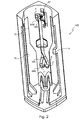
全体参照符号1で表わされる図1の容器はマスカラ容器であって、
本図では垂直方向である長手方向に延在し、底ゾーン11と自由縁部12が設けられた細長い本体と、
底部21とネック部22を備え、本体内に全てが含まれるように適合されると同時に、本体内で休止低位置と作動高位置の間で並進移動可能である、マスカラを含む貯留部20と、
シャフトが貯留部のネック部22を通過するその貯留部に対して再装填配置形態で貯留部の中に押し込まれるとき化粧品が装填されるように適合された塗布器32によって終端するシャフト31を備える塗布部材30と、
塗布部材30に接合され、実質的に引き込められた配置形態に到達するまで、本体内に係合されるように適合されたキャップ40(容器がバッグ内またはポケット内にあるとき本体から不意に偶発的に引き出されることを可能にするには不充分なほどの、最大限でも極めて僅かな把持しか使用者の指に与えない)とを主に備える容器である。
The container of FIG. 1 represented by the general reference number 1 is a mascara container,
In this figure, an elongate body extending in the longitudinal direction, which is the vertical direction, provided with a bottom zone 11 and a
A
The
本体は互いに接合された1つまたは複数の部分によって形成されてもよい。本明細書で検討される実施例では、本体は、なんらかの特定の断面(円形、長方形、多角形、または他の形)の、両端の開いた管10Aと、特にその管の底面を構成するようにその管の低部内で恒久的に定位置内に置かれるように適合された取付け式ケージ形成部分10Bとを備える。このケージは本明細書では長手スロット14および長手開口部15を備える。2つの部分のこの配置形態は2つの部分10Aと10Bを構成する材料が、例えば管には金属材料、部分10Bにはプラスチック材料など、個別に選択されることを可能にする。当然ながら、ここに表わされない変化形態として、本体は、例えば成形で得られるなど、単一部分として形成されてもよい。
The body may be formed by one or more parts joined together. In the embodiments discussed herein, the body is configured to define an
本体10A+10Bと貯留部20との間に弾性圧縮可能な案内デバイスが配置される。このデバイスは、
本体10A+10Bと貯留部20とのそれぞれの2つの接触表面の間に配設されるバネ61において、これらの接触表面は本明細書では貯留部に接合され、本明細書ではネック部22付近の貯留部の上部分を取り囲む環状部位62と、本明細書では取付け式ケージ10Bの上縁表面によって構成される、本体10A+10Bに接合された接触表面とによって構成される(この取付け式ケージの幾何学形状を考えると、この上縁表面はC字形状である)、バネ61と
本体と貯留部の間に別々に分配される2つの相補的部位、即ち、
全般的に本体の長手方向に配設される中空の案内トラック64と、
その案内トラック内に係合される追従フィンガ65とを備える。
An elastically compressible guide device is disposed between the
In the
A
And a
中空案内トラック64は本明細書では本体によって、より詳しくは取付け式部分10Bによって担持されるが、追従フィンガ65は貯留部によって担持される。しかしながら、当然のことながら、ここに表わされていない変化形態では状況が逆になってもよい。
The
この中空案内トラック64は、追従フィンガにとっての安定位置を構成するように適合された角形状ゾーンをそれぞれが備える2つの端部位64Aと64Bを備える。より詳しくは、これら2つの角形状ゾーンは同じ方向に配向され、これらの先端部位の一方、64Aは、対応する角形状ゾーンを中央部が形成するW形状ゾーンを備える。バネ61は、追従フィンガをそれらの角形状ゾーンの一方または他方に向けて押しやるように配設される。これは図2および図3を参照して詳述される。
This
追従フィンガ65は、容器の長手方向と概ね並行に配向されるアームの端部65Aに取り付けられることが好ましく、その他方の端部65Bは、その追従フィンガを担持する部位に連節される。
The
追従フィンガが貯留部によって担持される、本明細書で検討される実施例では、アームの端部65Bはその貯留部の底部21の下で連節されることができるように湾曲される。
In the embodiment discussed herein where the tracking finger is carried by the reservoir, the
バネが貯留部を本体から外方に押しやるとすると、追従フィンガはその貯留部によって外方に押しやられる。そのような理由から、その追従フィンガのための安定位置を画定する中空案内トラックの角形状ゾーンAおよびBが外方に配向される(即ちゾーンが外方を指す)。追従フィンガが本体によって担持されるのに対し、中空案内トラックが貯留部によって担持される場合、案内トラックの角形状ゾーンは本体の底部の方へと配向されるべきである。 When the spring pushes the storage part outward from the main body, the follower finger is pushed outward by the storage part. For that reason, the square zones A and B of the hollow guide track that define a stable position for the following finger are oriented outwards (ie the zones point outward). If the follower finger is carried by the body while the hollow guide track is carried by the reservoir, the angular zone of the guide track should be oriented towards the bottom of the body.
中空案内トラックの詳細は図2および図3によって示される。 Details of the hollow guide track are shown by FIGS.
当然のことながら、追従フィンガは、文字Aによって識別される部位64Aの角形状ゾーンにあるとき、貯留部が安定最大押込配置形態で安定して留まるように安定位置にあるのに対し、追従フィンガは、文字Bによって識別される部位64Bの角形状ゾーンにあるとき、貯留部は安定最小押込め配置形態にある。実際には、フィンガは少なくとも1つの他の低位置を有して、貯留部に対して、文字Aによって画定されるよりも大きな押込めの配置形態を画定する(CおよびC’によって示されるこれらの低位置は、上述のW形状ゾーンを形成する2つのV’字の基部に位置付けられる。しかしながらこれは不安定な配置形態である。より詳しくは、バネに抗して貯留部を押し下げることによって、追従フィンガはW形状部位のそれらの中空部CまたはC’の一方の中へもたらされることができ、次いで文字Bによって記される位置に到達するまで案内トラックを追従することを可能にされる。
Of course, when the follower finger is in the square zone of the
実際には、貯留部が底部の方へ押される場合に追従フィンガが中空部の一方にだけ、本明細書では右側の中空部にだけ選択的に係合されることを保証するように、中空案内トラックの端部位64Aの底部に逆止めステップ100が形成される。これは、ステップ100の位置で案内トラックの深さを増大すれば充分である。次いで貯留部への押圧の解放が、貯留部がゾーンAによって画定される配置形態を達成することを可能にする。再度貯留部を押圧すると、追従フィンガが左側の中空部を通り越し、次いで高端部位64Bの方へ上がるようになる。
In practice, when the reservoir is pushed towards the bottom, the follower finger is hollowed to ensure that it is selectively engaged with only one of the hollows, in this case only with the right-hand hollow. A
当然のことながら、追従フィンガがそのような中空部CまたはC’を通り越すときのその軸方向の位置は、位置Aから位置B、また位置Bから位置Aに移動するために通り越すことが必要となるニュートラルの押込め位置を構成する(実際にはW形状部位の2つの中空部CおよびC’は本体に対して実質的に同一のレベルにある)。 Of course, the axial position when the follower finger passes through such a hollow C or C ′ needs to pass in order to move from position A to position B and from position B to position A. (In fact, the two hollow portions C and C ′ of the W-shaped portion are at substantially the same level with respect to the main body).
同様に、高端部位の文字Aによって記される他方の角形状ゾーンには、逆止めステップ200が設けられて、追従フィンガがその位置Bにある配置形態から貯留部が押し込められる場合に、追従フィンガが必ず戻り部位の一方を部位62A、本明細書では右の分枝部の方へ追従することを保証する。
Similarly, the other rectangular zone marked by the letter A at the high end portion is provided with a
したがって、本体と貯留部の間に位置付けられた弾性圧縮可能な案内デバイスは、貯留部の休止低位置を決定する安定引込み配置形態と、その貯留部の作動高位置を決定する最大伸張配置形態とを有することが明らかであり、それらの配置形態の一方から他方へのデバイスの移動は、バネに抗した安定引込み位置を超える引き込みによって行われ、デバイスは本体と貯留部の一方に、概ね本体の長手方向に配設された中空案内トラックを備え、本体と貯留部の他方には、少なくともデバイスがその最大伸張配置形態にあるときにその中空案内トラックに係合される追従フィンガを備える。 Therefore, the elastically compressible guide device positioned between the main body and the storage part includes a stable retracting arrangement form for determining the resting low position of the storage part, and a maximum extension arrangement form for determining the operating high position of the storage part. The movement of the device from one of these arrangements to the other is done by retraction beyond the stable retraction position against the spring, and the device is generally in one of the body and the reservoir, generally in the body. A longitudinally disposed hollow guide track is provided, and the other of the body and reservoir is provided with a follower finger that engages at least the hollow guide track when the device is in its maximum extended configuration.
当然のことながら、追従フィンガと低端部位の角形状ゾーンAとの協働が貯留部の休止低位置を決定する。他方、有利には、ケージ10Bは、貯留部に設けられた相補的接触表面と共にその貯留部の作動高位置を画定する機械的当接部を備えるように有利に設計される。これは追従フィンガがその高位置内に押しやられることを回避する(いずれにしても過度に押しやられないようにする)。これらの当接部は、本明細書ではケージ10Bの長手スロット14に沿って設けられたショルダ部18であり、貯留部の高位置でこれらの当接部と協働するように適合された接触表面は、バネが凭れ掛ってくる環状接触表面によって構成される。
As a matter of course, the cooperation between the follower finger and the rectangular zone A at the lower end portion determines the resting low position of the reservoir. On the other hand, advantageously, the
本発明の一態様によると、バネ自体が、追従フィンガをそれが位置Bに到達するまで位置Aから移動させることを可能にするように寸法決めされないことが可能である。より詳しくは、フィンガのその位置Bから位置Aの方向への移動を制動するように、案内トラックの近傍にその角形状ゾーンB付近で取付け式弾性部材67が設けられる。当然のことながら、バネの推進力から引き継いで使用者が容器に対して特定の作用を及ぼすことによって、位置Bに到達する追従フィンガの移動が得られたとしても、使用者が、その弾性部材を通り越させるのに充分な力を掛けることによって、追従フィンガをその位置Bにもたらす動きとは反対の動きを成すまで、追従フィンガは通常その位置Bに留まる。正確には、使用者の指によるキャップの把持を可能にするのに充分な距離分キャップが本体から突き出るように、貯留部がキャップを押しやるのに充分にバネが強力であればよい。
According to one aspect of the present invention, the spring itself may not be sized to allow the follower finger to move from position A until it reaches position B. More specifically, a mounting type
この取付け式弾性部材、本明細書では弾性ストリップは、有利には、追従フィンガがその位置Bから位置Aに移動する際に追従フィンガによって掃かれるボリュームに侵入できるようにトラックに対して配設される。これは、この移動は、貯留部自体の重量よりも実質的に大きくなるよう調整することの容易な、そのブレードを変形させるのに充分な力と、塗布器に化粧品を再装填する作業の度に貯留部に掛けられる適度な推進力(特に、マスカラ容器が典型的に備えるワイパーを通り越すためであるが、ワイパーは用途に応じて省略されてもよい)とを掛けることが必要であることを意味する。これは、フィンガが重力にも関わらずその位置に保たれることを保証する。 This mounted elastic member, here the elastic strip, is advantageously arranged relative to the track so that it can enter the volume swept by the follower finger as it moves from its position B to position A. The This is because the movement is easy to adjust to be substantially larger than the weight of the reservoir itself, enough force to deform the blade and every time the applicator is reloaded with cosmetics. It is necessary to apply a moderate propulsive force applied to the storage part (especially for passing through the wiper typically included in the mascara container, but the wiper may be omitted depending on the application). means. This ensures that the finger is kept in that position despite gravity.
したがって、当然のことながら、追従フィンガの役割は、Aにおいては、貯留部をその休止低位置に保持するためにW形状部位の角形状ゾーンと協働すること、またBにおいては、使用者が貯留部をその作動高位置から前記休止低位置に移動させることを望むときに通り越すべき「抵抗」点を構成するために取付け式弾性部材と協働することである。 Thus, of course, the role of the follower finger is that in A, it cooperates with the angular zone of the W-shaped part to hold the reservoir in its resting low position, and in B, the user Cooperating with a mounted elastic member to establish a “resistance” point to be passed when it is desired to move the reservoir from its operating high position to the rest low position.
有利には、中空案内トラックの端部位64Aと64Bは単一の中間トラック64Cによって連結される。しかしながらここに表わされていない変化形態として、これらの端部位は、それらの高端部位と低端部位の間の追従フィンガの上昇用と下降用にそれぞれが設定された並行トラックのセクションによって連結されてもよい。
Advantageously, the
より詳しくは、有利には、低いW形状部位は大きなハート形状部位(本明細書では逆転している)を形成し、高部位は大きなドロップ形状部位の一部を形成し、これらのハート形状部位とドロップ形状部位は、その単一中間部位64Cに接合する先の尖った接合ゾーンを有する。角形状ゾーンに関して以上に述べられたことと同様に、追従フィンガがその単一中間部位を退出する際に、それにハート形状またはドロップ形状の適切な分枝部を追従させる追従フィンガへの案内効果を保証する、ハート形状部位およびドロップ形状部位と中間部位との接合部には逆止めステップ300および400が設けられる。
More particularly, advantageously, the lower W-shaped part forms a large heart-shaped part (reversed herein) and the high part forms part of a larger drop-shaped part, these heart-shaped parts And the drop-shaped part has a pointed joining zone that joins to its single
図1では、追従フィンガ65を担持するアーム65Bは、追従フィンガがその安定位置Aにあるとき圧縮した状態で動作することに留意されたい。これは、弾性圧縮可能なデバイスのアセンブリの要部が貯留部と本体の横壁同士の間に位置付けられることを可能にするのに役立つ。これは、そのデバイスの存在にも関わらず、本体の内側ボリューム内の貯留部のボリュームを最大化することを可能にする助けとなる。
Note that in FIG. 1, the
貯留部のその高位置と低位置の間の移動を案内することは、専ら追従フィンガが中空案内トラックと協働することによって行われてもよい。 Guiding the movement of the reservoir between its high and low positions may be done exclusively by the tracking finger cooperating with the hollow guide track.
しかしながら、有利には、この案内は、本明細書では貯留部に形成された参照符号25のランナの、本明細書ではケージ10Bに形成されたリブまたは畝部19との協働によって完成される。したがって、これらの部材19および25によって完成される場合もある弾性圧縮可能なデバイスは、弾性圧縮可能な案内デバイスを構成する。
Advantageously, however, this guidance is completed by the cooperation of a runner with
さらに別の変化形態によると、中空案内トラック全体がハート形状であり、そのW字形状部分は低端部位を構成し、尖り部は高端部位を構成する。 According to yet another variant, the entire hollow guide track is heart-shaped, its W-shaped part constituting the low end part and the sharp part constituting the high end part.
このデバイスの一部は取付け式部分10Bに取り付けられることが以上に述べられている。このような取付け式部分を備える本体の1つの利点は、取付け式部分と貯留部の間の定位置にそのデバイスを置くことが管10Aの外側で行われてもよいこと、またアセンブリ10B+20の管10A内の、弾性圧縮可能デバイスの部材との係合が、その取付け式部分およびその貯留部との協働のための配置形態で、これらの部材が定位置に保たれることを保証するということである。
It has been stated above that a part of this device is attached to the mounting
この取付け式ケージが有利には、中空案内トラックが設けられているそのスリーブの内側ゾーンに面した長手方向スロット14を有するスリーブの形状を有する(特に図2を参照)のは、特に、バネおよび追従フィンガと共同して貯留部をケージ内で定位置に置くことをし易くするためである(したがってこのケージは概ねC字形状の断面を有する)。したがって、アーム65Aの湾曲部65Bが貯留部の底部の適切なチャネルに位置決めされると、スロットを通した貯留部の横方向の係合は、追従フィンガが中空案内トラックの任意のゾーン内に位置決めされることを可能にし、そのようにして得られた配置を定位置に保持することを保証するには、アセンブリを軸方向に管内に係合させるだけで充分となる。
This mounted cage advantageously has the shape of a sleeve with a
長手方向スロット14は、そのスリーブの内側ボリュームの幅と同じ幅を有してもよく、これは、貯留部のそのスリーブ内への容易な係合を可能にする。変化形態として、スロットは僅かに狭い。これは、ほぼ同じように容易な係合を可能にしながら、アセンブリが管10A内に位置決めされる間保持効果ももたらす。
The
スロット14から離隔されたスリーブの残りの壁に有利に設けられてもよい横方向開口部15は、スリーブが軽くなることを可能にしながら、スリーブの内側とその中に埋め込まれなければならない部材とにアクセスをもたらす。
A
スリーブは、追従フィンガ63を担持するアームの湾曲部の存在を考慮して、貯留部の底部の形態に相補的であるように形成された底部を有利に備える。 The sleeve advantageously comprises a bottom formed to be complementary to the form of the bottom of the reservoir, taking into account the presence of a curved portion of the arm carrying the follower finger 63.
図3において、底部の厚みに横方向スロット16が存在することに留意されたい。この横方向のスロットは2つのC字形状の部分17および17’が定位置内に置かれるのを可能にする。C字形状の部分17および17’は、スリーブが管内に係合されるときそれら自体をそれらの後部位17Aによって管の内側壁に固定しながらそれらの端部17Bによって互いに凭れ掛かるよう協働するように適合される(図6参照)。
Note that in FIG. 3, there are
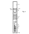
図4および図5は組み立て後の図1の容器を表す。 4 and 5 represent the container of FIG. 1 after assembly.
図4において、キャップと塗布部材のアセンブリとは本体内に引き込まれている。より詳しくは、キャップの自由面は本体の自由縁部と同一平面であることが分かる。前述のとおり、バッグまたはパケット内に含まれた物体によって不意に捕えられるほど充分な把持をキャップが与えなければ、この引き込みは完全である必要はない。 In FIG. 4, the cap and the applicator assembly are drawn into the body. More particularly, it can be seen that the free surface of the cap is flush with the free edge of the body. As noted above, this retraction need not be complete unless the cap provides sufficient grip to be caught unexpectedly by objects contained within the bag or packet.
この配置形態では、追従フィンガは図3の位置Bにある。 In this arrangement, the follower finger is at position B in FIG.
使用者がマスカラを塗布することを望むとき、使用者は、追従フィンガがW字形状部位の適切な中空部CまたはC’を通り越すことを可能にするように、それによって、フィンガが上述の中空部を通り越した後に位置Bの方へ脱出することができるということを利用して、バネが貯留部を上昇させることを可能にするように、キャップの自由面を押圧する。次いで塗布部材が貯留部に対して凭れ掛かることから、貯留部の上昇を可能にする追従フィンガの上昇は、キャップを含む塗布部材の上昇も可能にする。次いで使用者はキャップを把持することができ、必要に応じて、貯留部がその最大引出し位置にもたらされるまでキャップの上昇を続けることができる。次いでフィンガはその位置Bにあり、取付け式弾性部材の存在によってそこに留まる。 When the user desires to apply the mascara, the user can allow the follower finger to pass through the appropriate hollow C or C ′ of the W-shaped part, so that the finger is hollow as described above. Taking advantage of being able to escape towards position B after passing the part, the free surface of the cap is pressed to allow the spring to raise the reservoir. Next, since the application member hangs against the storage portion, the rise of the follower finger that enables the storage portion to rise also allows the application member including the cap to rise. The user can then grip the cap and, if necessary, continue to raise the cap until the reservoir is brought to its maximum withdrawal position. The finger is then in its position B and remains there due to the presence of the mounted elastic member.
ここで貯留部と塗布部材のシャフトとには、貯留部がその最大引出し位置に到達していない間、貯留部とその塗布部材を連係する相補的軸方向部材が有利に設けられることは注目に値する。これらの相補的軸方向連携部材は有利に密閉機能を実行する。 It should be noted that the storage portion and the shaft of the application member are advantageously provided with complementary axial members that link the storage portion and the application member while the storage portion has not reached its maximum withdrawal position. Deserve. These complementary axial linkage members advantageously perform a sealing function.
図1で示されるように、2つの部分が貯留部20のネック部に位置付けて取り付けられるように適合される(実際には接合される。即ち確実に接合される)。 As shown in FIG. 1, the two parts are adapted to be positioned and attached to the neck portion of the reservoir 20 (actually joined, ie, securely joined).
貯留部の上部でそのネック部にわたって係合するように適合されたワイパー形成部70、および
ワイパー形成部にキャップをするように貯留部の端部に係合するように適合され、塗布部材のシャフトによって担持された突起部35と協働するように適合された密閉部分80。
A
ワイパー形成部は、使用者が塗布部材を貯留部から取り出す際に塗布器と共に出てくる化粧品の量を制御する目的を有する。ワイパー形成部は典型的には塗布器を制御された方法で拭う能力がある可撓性材料の一部である。したがってこの部分は、実際には塗布器の形態によって画定される形態を有する。このワイパー形成部分は、塗布部材が貯留部内でその再装填配置形態にあるとき突起部35が出て凭れ掛かる着座を形成することによって上述の突起部35と協働するように適合された密閉接触表面を形成する狭窄部71を備える。その狭窄部の下に、任意の知られている適切なタイプのワイピングリップ部72が位置付けられる。
The wiper forming part has the purpose of controlling the amount of cosmetics that comes out with the applicator when the user takes out the application member from the storage part. The wiper forming part is typically part of a flexible material capable of wiping the applicator in a controlled manner. This part thus has a form that is actually defined by the form of the applicator. The wiper forming portion is a hermetic contact adapted to cooperate with the above-described
より詳しくは、突起部は、密閉接触表面71に対して軸方向に付けられるように適合されたシールが有利に設けられた密閉部位35Aを備える。有利には、密閉接触表面は、狭窄部を超えてワイパー形成部分70に係合するように適合されたプラグ形成部位35Cによって完成される。
More particularly, the protrusion comprises a sealing
突起部35は本体35Bを有し、本体35Bは、キャップの方に広がる、全体に円錐台形状を有する横方向の接触表面35Dを密閉部位35Aから離隔して備える。
The
密閉部分80は、複数の剛性セクタ81と可撓性セクタ82が円周に沿って形成されたカラーを備える。カラーによって、密閉部分80はそれが本体の内側断面よりも大きな横方向寸法を有する弛緩配置形態と、可撓性セクタの圧縮によってそれが本体の内部ボリューム内に閉じ込められる狭窄配置形態とを備える。これらの剛性セクタは、有利には、可撓性部位によって密閉部分80の下部分を構成する剛性冠部84に連結される。可撓性セクタに関しては、それらは有利には、冠部とそれが一体的に形成された剛性セクタとをオーバモールディングすることによって得られる。
The sealing
少なくとも剛性セクタ81は、突起部35の横方向接触表面35Dに対して軸方向に係合するように適合されたリム81Bを、カラーの内側縁部に沿って備える。有利には、リム82Bも可撓性セクタに設けられる。さらに、これらのセクタは、有利には、外側リム81C、または82Cさえも備える。
At least the
実際、密閉部分80の低部位を構成する冠部84は、スカートにおいて、その軸方向寸法が、リム81Bと狭窄部71の間の軸方向距離が、ゾーン35Aに設けられる可能性のあるシールが圧縮されるまで密閉部位35Aが密閉接触表面71に対して付けられるときに、突起部35の横方向接触表面に対するリム81Bの係合が得られるように設定されることを可能にするスカートである。このように、横方向接触表面に対するリムの係合は、これらの密閉部材を定位置に保持する。
In fact, the
一変化形態として、突起部は、少なくともその部分35Aに関しては、突起部が密閉部分80のその着座に来るとき弾性圧縮される能力がある材料から形成される。
As a variant, the protrusion is made of a material that is capable of being elastically compressed when it comes to its seating of the sealing
リム81Bと接触面35Dのこの協働の相補的役割は、カラーがその狭窄配置形態に維持される間、この協働が貯留部と塗布部材の軸方向の連係をもたらすということであり、これは使用者によってキャップに掛けられる、したがって塗布部材に掛けられる引出し移動が、バネ61の力とは関係なく、貯留部に転送されることを可能にして、貯留部がその高作動位置に到達するまでその上昇の終わりを貯留部にもたらすようにする。
The complementary role of this cooperation between the
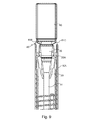
図8は、使用者が塗布部材を部分的に貯留部内に係合させた配置形態、即ちシャフトが既にワイパー形成部分70および密閉部分80を通過し、突起部が密閉部分80内に係合しかけているところを表す。カラーはその弛緩配置形態にある。
FIG. 8 shows an arrangement in which the user partially engages the application member in the storage portion, that is, the shaft has already passed through the
ワイパー形成部分70を通過することによって、塗布器は抵抗に遭遇したが、貯留部は移動していない。これは、ワイパーによって生じる抵抗が貯留部と本体の間の抵抗点の抵抗よりも小さいことによる。
By passing through the
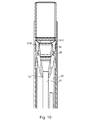
押し込み移動を続けると(図9参照)、密閉部分80のスカートが本体内に係合する間、突起部の密閉部位を密閉接触表面71にもたらす。そのことの効果は、カラーの閉じ込め効果を開始することである。次いで内側リム81Bは、軸方向に、突起部の後横方向接触表面のレベルになる。スカートは、本体の自由縁部と共に、ランプ効果をもたらす。ランプ効果は、外側リム81C、さらに82Cの存在によって増幅されて、狭窄配置形態が達成されるまで本体の自由縁部と共にカラーの変形を引き起こす。この方法で、貯留部の本体内への下降がカラーの本体内への進入を引き起こし、これによってリム81Bが互いに近づき、したがってそれら同士が横方向の接触表面35Dに沿って係合するようになる(図10)。次いでカラーはその狭窄配置形態になる。
Continuing the push-in movement (see FIG. 9) brings the sealing portion of the protrusion to the sealing
カラーを本体内に閉じ込めることは使用者からの力を必要とする。これは取付け式弾性部材を通り越すのに必要な力に加えられる。この弾性部材が取付け式部材であるということは、適切な剛性の部材を選択することによって、貯留部の本体内への下降の開始を引き起こすことに成功するように掛ける力の大きさを調整することを可能にする。 Enclosing the collar within the body requires power from the user. This is in addition to the force required to pass the mounted elastic member. The fact that this elastic member is a mountable member adjusts the magnitude of the force applied to succeed in triggering the descent of the reservoir into the body by selecting an appropriately rigid member. Make it possible.
この移動は、本明細書ではキャップが本体へ同一平面上で引き込こめられることに対応する(図11)、貯留部がその最大押入れ配置形態に到達する時点まで続く。 This movement corresponds here to the cap being retracted into the body on the same plane (FIG. 11) until the reservoir reaches its maximum indentation configuration.
図12から図15は本発明による容器の一変化形態を部分的に表わす。これは、特に貯留部がその高作動位置にあるとき追従フィンガが位置付けられるその部分に関して、弾性圧縮可能なデバイスの構造によって上述の容器とは区別される。 12 to 15 partly represent a variant of the container according to the invention. This is distinguished from the container described above by the structure of the elastically compressible device, particularly with respect to that part where the tracking finger is positioned when the reservoir is in its high operating position.
上述の容器の要素と類似の容器の要素は、上述の容器に使用された参照符号に数字500を加えた参照符号によって示される。 Container elements similar to those of the container described above are indicated by the reference numeral used in the container described above plus the number 500.
したがって、図12の案内トラック564は、図2および3と同じ幾何学的形状を有する低端部位564Aを備える。しかしながら、部位564Aに単一部位564Cによって連結された高端部位564Bは、それがトラックの長手断面であり、その低部には空洞564Dが形成されるということによって、図2および3のドロップ形状とは異なる幾何学形状を有する(図15参照)。この空洞はランプ564Eによって中空案内トラックの底部に連結する。ランプ564Eの役割は後ほど明らかになる。ここに表わされている実施形態では、案内トラックはその空洞の位置で広くなる。
Accordingly, the
その空洞には、分枝部567Aおよび567Bが下方に長手方向に、即ち案内トラックの残りの部分の方に配向されたU字形状を有する取付け式部分567が係合される。これらの分枝部は、追従フィンガを受け取ることが可能な空間567Cをそれらの間に形成するように共形にされる。これらの分枝部は、フィンガによるその空間からの脱出が、その追従フィンガの幅が得られて、狭窄部が拡がるまで分枝部同士を強制的に隔てることによってのみ行われることができるように、U字の底部に対して軸方向に反対側の端部で追従フィンガの幅よりも狭い狭窄部を形成するように、対向し合う突起部を備える。
Engaged in the cavity is a mounting
この取付け式部分の厚みは、ケージの内方に配向されたその面が、トラックがケージ内で定位置にあるときトラックの残りの部分の底部と実質的に同一平面となるようなものである。 The thickness of this mountable part is such that its face oriented inward of the cage is substantially flush with the bottom of the rest of the track when the track is in place in the cage. .
追従フィンガが分枝部同士を離そうとするとき、実際にそのケージの壁と並行に起こりつつある変形が回避されるように、このU字形状部分は、ケージ510Bの厚みに形成されたスロット内に係合される(図14参照。案内トラックの一方の横側面だけが表わされている)。
This U-shaped portion is a slot formed in the thickness of the
追従フィンガは空洞の底部の方へ、容器の長手方向に対して横断方向に弾性的に押し付けられる。これは、例えばアーム565Aに対して弾性材料や適切な予応力を備えたアセンブリを選択した結果である。
The follower finger is elastically pressed in a direction transverse to the longitudinal direction of the container towards the bottom of the cavity. This is a result of, for example, selecting an assembly with an elastic material or appropriate prestress for
貯留部がその高作動位置にあるとき、追従フィンガはU字形状部分の分枝部同士の間、またそのU字の底部とそれらの分枝部によって成形された狭窄部との間に形成された空間に係合される。 When the reservoir is in its high operating position, the follower fingers are formed between the branches of the U-shaped portion, and between the bottom of the U-shape and the constriction formed by those branches. Engaged in the space.
図15から明らかなように、貯留部が押し込み力を受けるとき、その力は貯留部によって追従フィンガに伝えられ、したがって追従フィンガは長手方向下方に押される。狭窄部が存在することを考えると、追従フィンガはその空間から自由に出ることができず、分枝部同士を強制的に離すのに充分な力がそれに掛けられざるを得なくなる。追従フィンガがその空間から出始める間、あるいはそこから出た後、ランプ564Eは追従フィンガを、案内トラックの残りの部分の底部のレベルに戻るように、強制的に後退させようとする(貯留部の軸線の方へ横方向に)。上述の容器内と同じ方法で追従フィンガを保持できる低端部位まで到達するように追従フィンガを案内トラックに沿って滑動させれば充分なので、貯留部に掛けられる移動を継続することは小さな力しか必要としない。図15では、追従フィンガは、案内トラックの底部で正常に滑動できる配置形態で、点線で表わされている。 As is apparent from FIG. 15, when the reservoir receives a pushing force, the force is transmitted to the follower finger by the reservoir, and therefore the follower finger is pushed downward in the longitudinal direction. Considering the presence of a constriction, the follower finger cannot leave the space freely, and a force sufficient to force the branches apart must be applied to it. While the tracking finger begins to exit the space or after it exits, ramp 564E attempts to force the tracking finger to retract back to the bottom level of the rest of the guide track (reservoir Sideways towards the axis). It is sufficient to slide the follower finger along the guide track so that it reaches the lower end where the follower finger can be held in the same manner as in the container described above. do not need. In FIG. 15, the follower fingers are represented by dotted lines in an arrangement that can normally slide at the bottom of the guide track.
使用者が貯留部をその高位置に上昇させることを望むとき、使用者が貯留部をその高位置にもたらすようにキャップを把持できる程度に、使用者はバネに少なくとも上昇を始めるのに充分な押圧をかければ充分である。この動きの終わりにおいて、取付け式部分の分枝部が案内トラックの残りの部分の底部と実質的に同一平面であるということは、追従フィンガが、U字形状の底部付近で分枝部同士の間に位置付けられた空間内に掛け止めによって係合するまで、分枝部に進入せずに、追従フィンガが分枝部の上を滑動することができるという利点を有する。このように分枝部は上昇中に抵抗に合わずに通り越されてもよい。 When the user desires to raise the reservoir to its high position, the user is at least enough to start raising the spring so that the user can grip the cap to bring the reservoir to its high position. It is enough to apply pressure. At the end of this movement, the branch of the mounted part is substantially flush with the bottom of the rest of the guide track, which means that the follower finger is located between the branches near the U-shaped bottom. It has the advantage that the follower finger can slide over the branch part without entering the branch part until it engages by a latch in the space positioned between them. In this way, the branch may pass over the resistance while climbing.
言い換えれば、U字形状部分の分枝部は、貯留部が本体内に下降する方向にのみ追従フィンガが通り越す抵抗点を構成する。 In other words, the branch part of the U-shaped part constitutes a resistance point where the follower finger passes only in the direction in which the storage part descends into the main body.
追従フィンガがアームによって担持される実施例では、追従フィンガが案内トラックの底部の方へ掛けられる圧力は、アームが取り付けられるための予応力によって有利に得られる。 In the embodiment in which the follower finger is carried by the arm, the pressure with which the follower finger is applied towards the bottom of the guide track is advantageously obtained by a prestress for the arm to be attached.
一変化形態として、565’で示された追従フィンガは、そのような横方向の予応力を貯留部の内側から離してもたらすように曲げられる弾性ブレード565A’に取り付けられてもよい。
As a variation, the tracking finger, shown as 565 ', may be attached to a
図16から図18は別の変化形態を表す。図12から図15の部分と類似の部分は、それらの図で使用された参照符号に数字100を加えた参照符号によって示される。
16 to 18 show another variation. Parts similar to those of FIGS. 12-15 are indicated by reference numerals used in those figures plus the
したがって図16から図18は、一部において、図12から図15の容器とは異なる容器について述べる。この容器は、本明細書では、離れることができないようにU字の底部から隔てて互いに連係された分枝部を備えた閉鎖開口部667Cを備えた取付け式部分によってU字形状部分が置き換えられているということによって図12から図15の容器とは異なる。
Accordingly, FIGS. 16-18 describe in part a container that differs from the container of FIGS. 12-15. This container is replaced here by a mounting part with a
この事例では、弾性圧縮可能な案内デバイスの動作は実質的に同じであるが、その差異は、追従フィンガが、空間667Cから脱出するために、貯留部の方に配向されるその部分の面のレベルに来るまで後退しなければならないということである。
In this case, the operation of the elastically compressible guide device is substantially the same, but the difference is that the surface of that portion of the surface where the tracking finger is oriented towards the reservoir to escape from the
追従フィンガ665は可撓性部位665Dによってそのアーム665Aに有利に連結される。このことによって、追従フィンガは、空間667Cから脱出できるように容器の長手方向に傾斜することができる。この事例では、追従フィンガの傾斜の効果は、その空間から退出できるようにフィンガの横壁がランプとしての働きをしてもよいということである。
The
図17は図13の追従フィンガの変化形態を表す。ここでは追従フィンガは、弾性可撓性ストリップ665A’によって担持され、追従フィンガが空間667Cから退出し易くするランプ665’Bを構成するように適合された傾斜横側面を備える。
FIG. 17 shows a variation of the following finger in FIG. Here, the tracking finger is carried by an elastic
図19は、貯留部と塗布部材の連係が、単に掛け止めの問題であることから、図7で表わされた部材よりも簡単な部材によって得られる変化形態を表す。 FIG. 19 shows a variation obtained by a simpler member than the member shown in FIG. 7 because the association between the reservoir and the application member is simply a latching problem.
図8から図11の容器の部材と類似のこのように表わされた容器の部材は、特に、それらの図で使用された参照符号に数字1000を加えた参照符号によって示される。 The container members thus represented which are similar to the container members of FIGS. 8-11 are indicated in particular by the reference numeral used in those figures plus the number 1000.
この容器は、主に、塗布部材へのその貯留部の連係を保証するために貯留部に設けられた部材の幾何学形状で、図1から図12の容器とは異なる。 This container is different from the containers of FIGS. 1 to 12 mainly in the geometrical shape of the member provided in the reservoir to ensure the linkage of the reservoir to the application member.
正確には、突起部の横方向接触表面の後ろで顎のように閉じる剛性セクタ81の役割は、ここでは、塗布部材の貯留部への進入の際に突起部によって通り越されることができるように、貯留部の内側表面に形成される簡単な隆起部1081によって果たされる。これらの隆起部は通り越す際の障害物となるが、そのことは、使用者が、貯留部を本体内に滑動させるために必要となる一時的に追加の力をもたらさなければならないことを意味する。当然ながら、貯留部と塗布部材が連係する配置形態で協働するこれらの隆起部のゾーンと突起部のゾーンとの傾斜を変化させることによって、いずれの方向でもそれらの隆起部を通り越すためにもたらさなければならない追加の力を調整することが可能である。塗布部材の貯留部内への係合の方向の長手方向に対する僅かな傾斜は、僅かな追加の力しか必要としないが、反対方向、即ち脱係合の方向で急な傾斜を選択すると強力な相互連係が可能になる。貯留部と塗布部材の連係、ならびに密閉機能を実現するために、例えばシールに適切な幾何学形状を選択するなど、他の変化形態も可能である。
Precisely, the role of the
当然のことながら、上述の様々な選択肢は様々な形で組み合わされてもよく、特に、追従フィンガを担持するアームを、図13で表わされているように可撓性ストリップと置き換えることによって、本発明による容器は図1から図12の構造を兼ね備えてもよい。さらに、弾性圧縮可能なデバイスは、一変化形態として、欧州特許第1721543号明細書で述べられる種類の冠部一式を備えてもよい。 Of course, the various options described above may be combined in various ways, in particular by replacing the arm carrying the tracking finger with a flexible strip as represented in FIG. The container according to the present invention may have the structure shown in FIGS. Furthermore, the elastically compressible device may comprise a set of crowns of the kind described in EP 1721543 as a variant.
Claims (16)
底区域(11)と自由縁部(12)が設けられた長手方向に延在する細長い本体と、
その化粧品を含み、本体内で、底区域付近の休止低位置と自由縁部付近の作動高位置との間で並進移動可能な、ネック部を備える貯留部(20)と、
本体と貯留部の間に位置付けられた弾性圧縮可能な案内デバイス(61、64、65、564、565、565’)において、貯留部の休止低位置を決定する安定引込み配置形態とその貯留部の作動高位置を決定する最大伸張配置形態とを有し、それらの配置形態の一方から他方へのデバイスの移動が、バネに抗した安定引込み位置を超える引き込みによって成され、デバイスが、本体と貯留部の一方に、本体の実質的に長手方向に配設された中空案内トラックを備え、本体と貯留部の他方には、少なくともデバイスがその最大伸張配置形態にあるときその中空案内トラック内に係合される追従フィンガを備える、弾性圧縮可能な案内デバイスと、
シャフト(31)を備える塗布部材(30)において、シャフトがキャップ(40)に接合され、シャフトが貯留部のネック部を通過する、その貯留部に対して再装填用配置形態にある貯留部内に押し込まれる際に化粧品が装填されるように適合された塗布器(32)によって終端し、そのキャップが、再装填配置形態で、貯留部を本体内にそれがその休止低配置形態に到達するまで押し込めることによって本体の内側に係合するように適合され、他方向では、塗布部材が貯留部および本体から引き出されることを可能にするように弾性圧縮可能な案内デバイスの作用下で本体から少なくとも部分的に引き出されるように適合される、塗布部材とを備える容器であって、
キャップを本体内に押し込む結果として弾性圧縮可能なデバイスがその最大伸張配置形態から退出する際に、追従フィンガの移動上に抵抗制動点を成すように、その案内トラックの近傍に取付け式弾性部材(67、567、565、565A’、665、665A’)が設けられることを特徴とする、容器。 In a paste or liquid cosmetic container,
A longitudinally extending elongated body provided with a bottom section (11) and a free edge (12);
A reservoir (20) comprising a neck portion, including the cosmetic product, and capable of translational movement between a resting low position near the bottom area and an operating high position near the free edge within the body;
In the elastically compressible guide device (61, 64, 65, 564, 565, 565 ′) positioned between the main body and the storage part, a stable retraction arrangement form for determining the resting low position of the storage part and the storage part A maximum extension arrangement that determines the operating height position, and movement of the device from one of the arrangements to the other is effected by retraction beyond a stable retraction position against the spring, wherein the device is One of the parts includes a hollow guide track disposed substantially longitudinally of the main body, and the other of the main body and the reservoir is engaged in the hollow guide track at least when the device is in its maximum extended configuration. An elastically compressible guide device with mating follower fingers;
In the application member (30) including the shaft (31), the shaft is joined to the cap (40), and the shaft passes through the neck portion of the storage portion. Terminate by an applicator (32) adapted to be loaded with cosmetics as it is pushed in, with its cap in the reload configuration until the reservoir is in the body until it reaches its resting low configuration Adapted to engage the inside of the body by pushing in and in the other direction at least partly from the body under the action of an elastically compressible guide device to allow the application member to be pulled out of the reservoir and the body A container comprising an applicator member adapted to be withdrawn automatically,
A mounting elastic member in the vicinity of the guide track so as to form a resistance braking point on the movement of the follower finger when the elastically compressible device exits its maximum extended configuration as a result of pushing the cap into the body. 67, 567, 565, 565A ′, 665, 665A ′).
Applications Claiming Priority (3)
| Application Number | Priority Date | Filing Date | Title |
|---|---|---|---|
| FR0805652A FR2936939B1 (en) | 2008-10-13 | 2008-10-13 | BOTTLE FOR LIQUID OR PASTY COSMETIC PRODUCT WITH REMOVABLE APPLICATION ELEMENT |
| FR08/05652 | 2008-10-13 | ||
| PCT/FR2009/051929 WO2010043802A1 (en) | 2008-10-13 | 2009-10-09 | Vial for a liquid or pasty cosmetic product with a retractable application element |
Publications (2)
| Publication Number | Publication Date |
|---|---|
| JP2012504996A JP2012504996A (en) | 2012-03-01 |
| JP5425916B2 true JP5425916B2 (en) | 2014-02-26 |
Family
ID=40639575
Family Applications (1)
| Application Number | Title | Priority Date | Filing Date |
|---|---|---|---|
| JP2011530533A Expired - Fee Related JP5425916B2 (en) | 2008-10-13 | 2009-10-09 | Liquid or paste cosmetic vials with retractable application elements |
Country Status (9)
| Country | Link |
|---|---|
| US (1) | US8287199B2 (en) |
| EP (1) | EP2346370B1 (en) |
| JP (1) | JP5425916B2 (en) |
| KR (1) | KR101611644B1 (en) |
| CN (1) | CN102186374B (en) |
| ES (1) | ES2400113T3 (en) |
| FR (1) | FR2936939B1 (en) |
| RU (1) | RU2494663C2 (en) |
| WO (1) | WO2010043802A1 (en) |
Families Citing this family (12)
| Publication number | Priority date | Publication date | Assignee | Title |
|---|---|---|---|---|
| WO2010106235A1 (en) * | 2009-03-16 | 2010-09-23 | L'oreal | Assembly including a system for packaging a product with a sealed closing |
| FR2989255B1 (en) * | 2012-04-11 | 2014-12-26 | Oreal | DEVICE FOR CONDITIONING AND APPLICATION. |
| US8998520B1 (en) * | 2012-10-17 | 2015-04-07 | Beryl L. Tanner | Makeup applicator assembly |
| FR3024338B1 (en) | 2014-08-04 | 2016-09-09 | Chanel Parfums Beaute | BOTTLE FOR LIQUID OR PASTY COSMETIC PRODUCT WITH REMOVABLE APPLICATION ELEMENT |
| FR3024340B1 (en) * | 2014-08-04 | 2016-08-19 | Chanel Parfums Beaute | MECHANICAL ATTACHMENT OF TWO PIECES OF A COSMETIC PRODUCT CONTAINER |
| CN205757926U (en) * | 2016-05-16 | 2016-12-07 | 汕头市京华塑胶有限公司 | A kind of pressing lip gloss |
| FR3053225B1 (en) * | 2016-06-29 | 2020-11-13 | Lvmh Rech | COSMETIC PRODUCT APPLICATOR DEVICE |
| USD840820S1 (en) * | 2016-08-10 | 2019-02-19 | F.S.Korea Industries Inc. | Insert for cosmetic container |
| FR3082713B1 (en) * | 2018-06-22 | 2021-09-17 | Oreal | SET INCLUDING A SYSTEM FOR PACKAGING AND APPLYING A PRODUCT, IN PARTICULAR A COSMETIC PRODUCT, AND A PROTECTION DEVICE FOR THE SAID SYSTEM |
| FR3097728A1 (en) * | 2019-06-28 | 2021-01-01 | L'oreal | Device for sampling and applying a cosmetic composition |
| CN113163035B (en) * | 2021-04-21 | 2023-04-21 | Oppo广东移动通信有限公司 | Guide rail assembly and electronic device |
| US20240034518A1 (en) * | 2022-07-27 | 2024-02-01 | Elc Management Llc | Closure mechanism for product container |
Family Cites Families (12)
| Publication number | Priority date | Publication date | Assignee | Title |
|---|---|---|---|---|
| GB834486A (en) | 1957-07-26 | 1960-05-11 | Laughton & Sons Ltd | Improvements relating to containers for toilet salves and the like |
| DE3426351A1 (en) | 1984-07-17 | 1986-01-23 | Pola Chemical Industries, Inc., Shizuoka | Container for cosmetics |
| FR2720238B1 (en) * | 1994-05-24 | 1996-08-30 | Oreal | Device for applying a perforated piston to a product, in particular makeup and / or care. |
| FR2730911B1 (en) * | 1995-02-24 | 1997-04-04 | Oreal | DEVICE FOR DISPENSING A LIQUID OR PULVERULENT PRODUCT COMPRISING A WRINKING MEMB |
| US20040119297A1 (en) * | 2002-12-24 | 2004-06-24 | Bella Joseph J. | Push-push sliding cosmetic container |
| JP2004217244A (en) * | 2003-01-14 | 2004-08-05 | Yoshida Industry Co Ltd | Slide case |
| FR2865910B1 (en) * | 2004-02-11 | 2006-04-28 | Rexam Reboul | COSMETIC, HYGIENIC OR PHARMACEUTICAL PRODUCT DISTRIBUTOR |
| FR2870092B1 (en) * | 2004-05-14 | 2006-07-21 | Dj Pack Sarl | CASE SET FOR LIP RED AND CLOSURE CAP |
| CA2607266C (en) * | 2005-05-10 | 2011-08-09 | Chanel Parfums Beaute | Container for a liquid, solid, pasty or powder cosmetic having a retractable dispensing element |
| US7429140B2 (en) * | 2005-06-21 | 2008-09-30 | Dj Pack | Case assembly for lipstick and associated closure cap |
| CN1891102A (en) * | 2005-07-01 | 2007-01-10 | Dj包装 | Case assembly for lip gloss and relative enclosed cover |
| JP2007061392A (en) * | 2005-08-31 | 2007-03-15 | Hidan:Kk | Knock type cosmetic container |
-
2008
- 2008-10-13 FR FR0805652A patent/FR2936939B1/en not_active Expired - Fee Related
-
2009
- 2009-10-09 US US13/124,090 patent/US8287199B2/en active Active
- 2009-10-09 WO PCT/FR2009/051929 patent/WO2010043802A1/en active Application Filing
- 2009-10-09 ES ES09756000T patent/ES2400113T3/en active Active
- 2009-10-09 CN CN2009801404599A patent/CN102186374B/en not_active Expired - Fee Related
- 2009-10-09 KR KR1020117010747A patent/KR101611644B1/en active IP Right Grant
- 2009-10-09 EP EP09756000A patent/EP2346370B1/en active Active
- 2009-10-09 JP JP2011530533A patent/JP5425916B2/en not_active Expired - Fee Related
- 2009-10-09 RU RU2011119106/12A patent/RU2494663C2/en not_active IP Right Cessation
Also Published As
| Publication number | Publication date |
|---|---|
| ES2400113T3 (en) | 2013-04-05 |
| US8287199B2 (en) | 2012-10-16 |
| RU2494663C2 (en) | 2013-10-10 |
| EP2346370A1 (en) | 2011-07-27 |
| JP2012504996A (en) | 2012-03-01 |
| CN102186374A (en) | 2011-09-14 |
| CN102186374B (en) | 2013-07-10 |
| FR2936939A1 (en) | 2010-04-16 |
| US20110200382A1 (en) | 2011-08-18 |
| EP2346370B1 (en) | 2012-12-05 |
| RU2011119106A (en) | 2012-11-20 |
| WO2010043802A1 (en) | 2010-04-22 |
| FR2936939B1 (en) | 2010-10-01 |
| KR20110084238A (en) | 2011-07-21 |
| KR101611644B1 (en) | 2016-04-11 |
Similar Documents
| Publication | Publication Date | Title |
|---|---|---|
| JP5425916B2 (en) | Liquid or paste cosmetic vials with retractable application elements | |
| JP6652962B2 (en) | Paste or liquid cosmetic container having a retractable application member | |
| US7841794B2 (en) | Container for liquid, solid, paste or powder cosmetic product with retractable applicator element | |
| US5909977A (en) | Dentifrice dispensing toothbrush with refillable cartridge | |
| KR100522309B1 (en) | Cosmetics brush | |
| KR101832205B1 (en) | Product applicator device and use thereof | |
| US20120248006A1 (en) | Container for a stick of a cosmetic or hygienic product having a retractable applicator element | |
| WO2008003894A2 (en) | Fluid product dispenser | |
| US8287201B2 (en) | Telescopic container for a pasty or liquid cosmetic product | |
| KR101625329B1 (en) | Stick-shaped cosmetic container | |
| CN111615345B (en) | Device for supporting cosmetic products | |
| EP3202278A1 (en) | Container for storing heterogeneous contents | |
| FR2864045A1 (en) | Viscous product e.g. cosmetic cream, distribution device, has hooking unit in contact with retention unit to permit axial displacement of differential piston that is in tight sliding contact in pusher for unblocking outlet of chamber | |
| JP3579108B2 (en) | Stick-shaped cosmetic feeding container | |
| US11903477B2 (en) | Refillable container | |
| EP0894453A2 (en) | Improvements to cosmetic pencils | |
| JP3865993B2 (en) | Feeding container | |
| FR3120290A1 (en) | Set of packaging and distribution of a cosmetic product and associated necessary | |
| KR101507513B1 (en) | Hardening anti-cosmetic dispenser | |
| FR2855820A1 (en) | RECHARGEABLE DISPENSER |
Legal Events
| Date | Code | Title | Description |
|---|---|---|---|
| A621 | Written request for application examination |
Free format text: JAPANESE INTERMEDIATE CODE: A621 Effective date: 20120802 |
|
| A977 | Report on retrieval |
Free format text: JAPANESE INTERMEDIATE CODE: A971007 Effective date: 20131015 |
|
| TRDD | Decision of grant or rejection written | ||
| A01 | Written decision to grant a patent or to grant a registration (utility model) |
Free format text: JAPANESE INTERMEDIATE CODE: A01 Effective date: 20131029 |
|
| A61 | First payment of annual fees (during grant procedure) |
Free format text: JAPANESE INTERMEDIATE CODE: A61 Effective date: 20131127 |
|
| R150 | Certificate of patent or registration of utility model |
Free format text: JAPANESE INTERMEDIATE CODE: R150 Ref document number: 5425916 Country of ref document: JP Free format text: JAPANESE INTERMEDIATE CODE: R150 |
|
| R250 | Receipt of annual fees |
Free format text: JAPANESE INTERMEDIATE CODE: R250 |
|
| R250 | Receipt of annual fees |
Free format text: JAPANESE INTERMEDIATE CODE: R250 |
|
| R250 | Receipt of annual fees |
Free format text: JAPANESE INTERMEDIATE CODE: R250 |
|
| R250 | Receipt of annual fees |
Free format text: JAPANESE INTERMEDIATE CODE: R250 |
|
| LAPS | Cancellation because of no payment of annual fees |