JP5425757B2 - Apparatus for processing liquid samples - Google Patents
Apparatus for processing liquid samples Download PDFInfo
- Publication number
- JP5425757B2 JP5425757B2 JP2010504015A JP2010504015A JP5425757B2 JP 5425757 B2 JP5425757 B2 JP 5425757B2 JP 2010504015 A JP2010504015 A JP 2010504015A JP 2010504015 A JP2010504015 A JP 2010504015A JP 5425757 B2 JP5425757 B2 JP 5425757B2
- Authority
- JP
- Japan
- Prior art keywords
- liquid sample
- flow
- liquid
- different
- sample
- Prior art date
- Legal status (The legal status is an assumption and is not a legal conclusion. Google has not performed a legal analysis and makes no representation as to the accuracy of the status listed.)
- Active
Links
- 239000007788 liquid Substances 0.000 title claims description 56
- 238000012545 processing Methods 0.000 title claims description 8
- 238000004458 analytical method Methods 0.000 claims description 32
- 239000003153 chemical reaction reagent Substances 0.000 claims description 27
- 238000000034 method Methods 0.000 claims description 12
- 238000005259 measurement Methods 0.000 claims description 6
- 239000012530 fluid Substances 0.000 claims description 4
- 238000003556 assay Methods 0.000 description 14
- 239000012491 analyte Substances 0.000 description 9
- 230000008901 benefit Effects 0.000 description 8
- 239000000126 substance Substances 0.000 description 7
- 230000000694 effects Effects 0.000 description 4
- 239000000376 reactant Substances 0.000 description 4
- 230000008878 coupling Effects 0.000 description 2
- 238000010168 coupling process Methods 0.000 description 2
- 238000005859 coupling reaction Methods 0.000 description 2
- 238000007689 inspection Methods 0.000 description 2
- 239000000463 material Substances 0.000 description 2
- 239000008280 blood Substances 0.000 description 1
- 210000004369 blood Anatomy 0.000 description 1
- 238000013461 design Methods 0.000 description 1
- 238000004090 dissolution Methods 0.000 description 1
- 238000001035 drying Methods 0.000 description 1
- 238000000635 electron micrograph Methods 0.000 description 1
- 238000005516 engineering process Methods 0.000 description 1
- 239000000203 mixture Substances 0.000 description 1
- 239000002245 particle Substances 0.000 description 1
- 210000002381 plasma Anatomy 0.000 description 1
- 210000003296 saliva Anatomy 0.000 description 1
- 210000002966 serum Anatomy 0.000 description 1
- 239000000758 substrate Substances 0.000 description 1
- 239000000725 suspension Substances 0.000 description 1
- 210000004243 sweat Anatomy 0.000 description 1
- 210000001138 tear Anatomy 0.000 description 1
- 238000012360 testing method Methods 0.000 description 1
- 210000002700 urine Anatomy 0.000 description 1
- XLYOFNOQVPJJNP-UHFFFAOYSA-N water Substances O XLYOFNOQVPJJNP-UHFFFAOYSA-N 0.000 description 1
Images


Classifications
-
- B—PERFORMING OPERATIONS; TRANSPORTING
- B01—PHYSICAL OR CHEMICAL PROCESSES OR APPARATUS IN GENERAL
- B01L—CHEMICAL OR PHYSICAL LABORATORY APPARATUS FOR GENERAL USE
- B01L3/00—Containers or dishes for laboratory use, e.g. laboratory glassware; Droppers
- B01L3/50—Containers for the purpose of retaining a material to be analysed, e.g. test tubes
- B01L3/502—Containers for the purpose of retaining a material to be analysed, e.g. test tubes with fluid transport, e.g. in multi-compartment structures
- B01L3/5027—Containers for the purpose of retaining a material to be analysed, e.g. test tubes with fluid transport, e.g. in multi-compartment structures by integrated microfluidic structures, i.e. dimensions of channels and chambers are such that surface tension forces are important, e.g. lab-on-a-chip
- B01L3/502746—Containers for the purpose of retaining a material to be analysed, e.g. test tubes with fluid transport, e.g. in multi-compartment structures by integrated microfluidic structures, i.e. dimensions of channels and chambers are such that surface tension forces are important, e.g. lab-on-a-chip characterised by the means for controlling flow resistance, e.g. flow controllers, baffles
-
- B—PERFORMING OPERATIONS; TRANSPORTING
- B01—PHYSICAL OR CHEMICAL PROCESSES OR APPARATUS IN GENERAL
- B01L—CHEMICAL OR PHYSICAL LABORATORY APPARATUS FOR GENERAL USE
- B01L3/00—Containers or dishes for laboratory use, e.g. laboratory glassware; Droppers
- B01L3/50—Containers for the purpose of retaining a material to be analysed, e.g. test tubes
- B01L3/502—Containers for the purpose of retaining a material to be analysed, e.g. test tubes with fluid transport, e.g. in multi-compartment structures
- B01L3/5027—Containers for the purpose of retaining a material to be analysed, e.g. test tubes with fluid transport, e.g. in multi-compartment structures by integrated microfluidic structures, i.e. dimensions of channels and chambers are such that surface tension forces are important, e.g. lab-on-a-chip
- B01L3/50273—Containers for the purpose of retaining a material to be analysed, e.g. test tubes with fluid transport, e.g. in multi-compartment structures by integrated microfluidic structures, i.e. dimensions of channels and chambers are such that surface tension forces are important, e.g. lab-on-a-chip characterised by the means or forces applied to move the fluids
-
- F—MECHANICAL ENGINEERING; LIGHTING; HEATING; WEAPONS; BLASTING
- F16—ENGINEERING ELEMENTS AND UNITS; GENERAL MEASURES FOR PRODUCING AND MAINTAINING EFFECTIVE FUNCTIONING OF MACHINES OR INSTALLATIONS; THERMAL INSULATION IN GENERAL
- F16K—VALVES; TAPS; COCKS; ACTUATING-FLOATS; DEVICES FOR VENTING OR AERATING
- F16K99/00—Subject matter not provided for in other groups of this subclass
- F16K99/0001—Microvalves
- F16K99/0003—Constructional types of microvalves; Details of the cutting-off member
- F16K99/0017—Capillary or surface tension valves, e.g. using electro-wetting or electro-capillarity effects
-
- B—PERFORMING OPERATIONS; TRANSPORTING
- B01—PHYSICAL OR CHEMICAL PROCESSES OR APPARATUS IN GENERAL
- B01L—CHEMICAL OR PHYSICAL LABORATORY APPARATUS FOR GENERAL USE
- B01L2300/00—Additional constructional details
- B01L2300/08—Geometry, shape and general structure
- B01L2300/0809—Geometry, shape and general structure rectangular shaped
- B01L2300/0816—Cards, e.g. flat sample carriers usually with flow in two horizontal directions
-
- B—PERFORMING OPERATIONS; TRANSPORTING
- B01—PHYSICAL OR CHEMICAL PROCESSES OR APPARATUS IN GENERAL
- B01L—CHEMICAL OR PHYSICAL LABORATORY APPARATUS FOR GENERAL USE
- B01L2300/00—Additional constructional details
- B01L2300/08—Geometry, shape and general structure
- B01L2300/0861—Configuration of multiple channels and/or chambers in a single devices
-
- B—PERFORMING OPERATIONS; TRANSPORTING
- B01—PHYSICAL OR CHEMICAL PROCESSES OR APPARATUS IN GENERAL
- B01L—CHEMICAL OR PHYSICAL LABORATORY APPARATUS FOR GENERAL USE
- B01L2300/00—Additional constructional details
- B01L2300/08—Geometry, shape and general structure
- B01L2300/0887—Laminated structure
-
- B—PERFORMING OPERATIONS; TRANSPORTING
- B01—PHYSICAL OR CHEMICAL PROCESSES OR APPARATUS IN GENERAL
- B01L—CHEMICAL OR PHYSICAL LABORATORY APPARATUS FOR GENERAL USE
- B01L2400/00—Moving or stopping fluids
- B01L2400/04—Moving fluids with specific forces or mechanical means
- B01L2400/0403—Moving fluids with specific forces or mechanical means specific forces
- B01L2400/0406—Moving fluids with specific forces or mechanical means specific forces capillary forces
-
- B—PERFORMING OPERATIONS; TRANSPORTING
- B01—PHYSICAL OR CHEMICAL PROCESSES OR APPARATUS IN GENERAL
- B01L—CHEMICAL OR PHYSICAL LABORATORY APPARATUS FOR GENERAL USE
- B01L2400/00—Moving or stopping fluids
- B01L2400/08—Regulating or influencing the flow resistance
- B01L2400/084—Passive control of flow resistance
- B01L2400/086—Passive control of flow resistance using baffles or other fixed flow obstructions
-
- F—MECHANICAL ENGINEERING; LIGHTING; HEATING; WEAPONS; BLASTING
- F16—ENGINEERING ELEMENTS AND UNITS; GENERAL MEASURES FOR PRODUCING AND MAINTAINING EFFECTIVE FUNCTIONING OF MACHINES OR INSTALLATIONS; THERMAL INSULATION IN GENERAL
- F16K—VALVES; TAPS; COCKS; ACTUATING-FLOATS; DEVICES FOR VENTING OR AERATING
- F16K99/00—Subject matter not provided for in other groups of this subclass
- F16K2099/0082—Microvalves adapted for a particular use
- F16K2099/0084—Chemistry or biology, e.g. "lab-on-a-chip" technology
Landscapes
- Chemical & Material Sciences (AREA)
- Health & Medical Sciences (AREA)
- Dispersion Chemistry (AREA)
- Analytical Chemistry (AREA)
- General Engineering & Computer Science (AREA)
- Engineering & Computer Science (AREA)
- General Health & Medical Sciences (AREA)
- Hematology (AREA)
- Clinical Laboratory Science (AREA)
- Chemical Kinetics & Catalysis (AREA)
- Mechanical Engineering (AREA)
- Automatic Analysis And Handling Materials Therefor (AREA)
- Investigating Or Analysing Biological Materials (AREA)
- Sampling And Sample Adjustment (AREA)
Description
〔技術分野〕
本発明は、液体サンプルを処理するための装置の分野に関する。
〔Technical field〕
The present invention relates to the field of devices for processing liquid samples.
〔背景〕
様々な種類の液体サンプルを処理するための装置は、たとえば医療処置の現場での分析で使用するのに望ましい。また、そのような装置は、血液、血漿、血清、汗、唾液、尿、涙液、試水、および、食品サンプルの懸濁液もしくは溶液を含む様々なサンプルを分析するために使用することができる。
〔background〕
Devices for processing various types of liquid samples are desirable for use, for example , in the field of medical procedures . Such devices can also be used to analyze a variety of samples including blood, plasma, serum, sweat, saliva, urine, tears, test water, and food sample suspensions or solutions. it can.
そのようなアッセイ装置(assay devices)は、たとえば、国際公開WO 2005/118139(アミック社(AMIC AB))、WO 2005/089082(アミック社(AMIC AB))、およびWO 03/103835(アミック社(AMIC AB))に記載されている。 Such assay devices are, for example, international publications WO 2005/118139 (AMIC AB), WO 2005/089082 (AMIC AB), and WO 03/103835 (Amic ( AMIC AB)).
他のアッセイ装置は、たとえば、米国特許5,458,852(バイオサイト(BIOSITE))および欧州特許1120164(ロシュ・ダイアグノスティックス社(ROCHE DIAGNOSTICS GMBH))に記載されている。 Other assay devices are described, for example, in US Pat. No. 5,458,852 (BIOSITE) and European Patent 1120164 (ROCHE DIAGNOSTICS GMBH).
英国特許2410086(ブリティッシュ・バイオセル・インターナット社(BRITISH BIOCELL INTERNAT LTD))には、液体の流れを決定するためのフローブロックを含むアッセイ装置が開示されている。 British Patent 2410086 (BRITISH BIOCELL INTERNAT LTD) discloses an assay device comprising a flow block for determining liquid flow.
米国特許6,296,020(バイオマイクロ・システムズ社(BIOMICRO SYSTEMS, INC.))には、受動バルブまたは停止手段の使用によってマイクロチャネルを通り抜ける流体の流れを制御する方法が開示されている。 US Pat. No. 6,296,020 (BIOMICRO SYSTEMS, INC.) Discloses a method for controlling the flow of fluid through a microchannel by use of a passive valve or stop means.
〔発明の開示〕
〔技術的課題〕
既知のアッセイ装置の幾つかにおいて、分析物を含むサンプルが加えられ、該サンプルは、乾燥した試薬が溶かされる流路に沿って流れる。試薬を含むようになったサンプルは、1つ以上の特性に関してサンプルが分析される分析ポイントまで流れて行く。この種の技術は、多数の問題を有する。
[Disclosure of the Invention]
[Technical issues]
In some known assay devices, a sample containing an analyte is added and the sample flows along a flow path in which the dried reagent is dissolved. Samples reagent became including way, it flows until analysis point samples for one or more characteristics are analyzed. This type of technology has a number of problems.
上記の技術に関する1つの問題は、試薬より前に分析ポイントにサンプルを到達させるやり方である。それは或る適用において望まれる。 One problem with the above technique is how to get the sample to the analysis point before the reagent. It is desirable in some applications.
別の問題は、試薬が分析ポイントに到達する前に分析ポイントを通るサンプルの特定の量を正確かつ再生可能に定めるやり方である。 Another problem is how to accurately and reproducibly define a specific amount of sample that passes through the analysis point before the reagent reaches the analysis point.
別の問題は、試薬が分析ポイントに到達する前に、サンプルを分析ポイントで長時間反応させるやり方である。 Another problem is how to react the sample for a long time at the analysis point before the reagent reaches the analysis point.
他の問題は、たとえば試薬の寿命および試薬の乾燥の程度によって試薬が別様に溶解するという事実から影響(effects)を取り除くことである。 Another problem is the reagent by the degree of drying of the life and reagents for example reagent is to remove the effect from the fact that otherwise dissolves (effects).
或るアッセイでの計測した信号は、試薬の量およびサンプルの量に依存する。多くのアッセイにおいて、或る種の粒子および/または或る種の分子が検出され、したがって、サンプルの量は明確に定められねばならない。 The measured signal in an assay depends on the amount of reagent and the amount of sample. In many assays, certain particles and / or certain molecules are detected, so the amount of sample must be clearly defined.
〔技術的解決策〕
本発明の1つの目的は、最新技術における問題のうちの少なくとも幾つかを軽減することである。
[Technical solution]
One object of the present invention is to mitigate at least some of the problems in the state of the art.
それは、液体サンプルを処理するための装置を第1の態様で提供する本発明を用いることによって達成され、この装置は、a)前記装置の表面に実質上垂直な突起部であって、高さ、直径、および、前記突起部間の距離を有し、前記表面の側方の、流体の毛管流れを発生できる突起部と、b)サンプルを受容するための少なくとも1つの領域と、c)前記液体を受容するための能力を有し、少なくとも2つの異なった毛管力を前記液体に及ぼす少なくとも1つのシンクと、d)サンプルを受容するための前記少なくとも1つの領域および前記少なくとも1つのシンクを連結し、少なくとも2つの異なった毛管力を前記液体に及ぼす少なくとも2つの流路と、e)前記少なくとも2つの流路の間の少なくとも1つの連結部と、を含む。 It is achieved by using the present invention which provides in a first aspect an apparatus for processing a liquid sample, the apparatus comprising: a) a protrusion substantially perpendicular to the surface of the apparatus, the height of which is A protrusion having a diameter and a distance between the protrusions and capable of generating a capillary flow of fluid laterally of the surface; b) at least one region for receiving a sample; c) Coupling at least one sink having the ability to receive liquid and exerting at least two different capillary forces on said liquid; and d) said at least one region for receiving sample and said at least one sink And at least two flow paths that exert at least two different capillary forces on the liquid, and e) at least one connection between the at least two flow paths.
アッセイ装置は、液体が流れるように毛管力を形成するために表面に実質上垂直な突起部を利用する。装置は、突起部の距離、形態、直径、および、高さにもよるが、毛管力が異なったフローチャネルに関して異なり得る、という事実を利用する。毛管力の差異は、所望の方向に流れを方向付けるために使用される。 The assay device utilizes a protrusion that is substantially perpendicular to the surface to create a capillary force for fluid flow. The device takes advantage of the fact that the capillary force can be different for different flow channels, depending on the distance, form, diameter, and height of the protrusions. The difference in capillary force is used to direct the flow in the desired direction.
また、本発明の範囲内に含まれるものは、サンプルを分析する方法および部品のキットである。 Also included within the scope of the present invention are methods for analyzing samples and kits of parts.
〔有益な効果〕
本発明の利点は、試薬の前にサンプルを分析ポイントに到達させることができることを含む。別の利点は、試薬が分析ポイントに到達する前に分析ポイントを通過するサンプルの特定の量を定めることができることである。さらに別の利点は、試薬が様々に溶解することによる影響を除去または軽減することができることである。
[Benefit effect]
Advantages of the present invention include the ability to allow the sample to reach the analysis point before the reagent. Another advantage is that a specific amount of sample can pass through the analysis point before the reagent reaches the analysis point. Yet another advantage is that the effects of various dissolution of reagents can be removed or reduced.
〔定義〕
本発明について詳細に説明および開示する前に、本発明が、本明細書に開示される特定の構造、処理工程、および、材料について、そのような構造、処理工程、分子、および、材料が多少変化し得るので、限定されない、ということが理解されるべきである。また、本発明の範囲が添付の特許請求の範囲およびそれに相当するものだけによって限定されるので、本明細書で使用される用語が、特定の実施形態を説明するためだけに用いられ、限定する意図ではない、ということが理解されるべきである。
[Definition]
Before describing and disclosing in detail the present invention, it will be appreciated that, for the specific structures, processing steps, and materials disclosed herein, such structures, processing steps, molecules, and materials may vary somewhat. It should be understood that it is not limited as it can vary. Also, the terminology used herein is used only to describe certain embodiments and is limited only as the scope of the invention is limited only by the appended claims and equivalents thereof. It should be understood that this is not the intention.
本明細書および添付の特許請求の範囲に使用されているように、「1つの(a)」、「1つの(an)」、および、「その(the)」という単数形は、文脈が明確に別のことを示していない限り、複数の指示物を含む、ということが留意されねばならない。以下の用語は、本明細書および特許請求の範囲にわたって使用される。 As used herein and in the appended claims, the singular forms “a”, “an”, and “the” are clearly contextual. It should be noted that it includes a plurality of instructions unless otherwise indicated. The following terms are used throughout the specification and claims.
「分析」は、サンプルが、たとえば、その定性的および/または定量的な組成に関して、その理解を得るために試験される処理を示すために本明細書において使用される。 “Analysis” is used herein to indicate the process by which a sample is tested to gain its understanding, for example, regarding its qualitative and / or quantitative composition.
「分析ポイント」は、計測が実行されるアッセイ装置(assay device)のポイントまたは領域を示すために本明細書において使用される。 An “analysis point” is used herein to indicate the point or area of the assay device where the measurement is performed.
「分析物」は、分析される物質、化学成分、または、生物学的成分を示すために本明細書において使用される。 “Analyte” is used herein to indicate the substance, chemical component, or biological component being analyzed.
「試薬」は、分析に関与する化学成分または生物学的成分を示すために本明細書において使用される。 “Reagent” is used herein to indicate a chemical or biological component involved in an analysis.
「サンプル」は、分析物を含む任意のものを示すために本明細書において使用される。 “Sample” is used herein to indicate anything that contains an analyte.
〔詳細な説明〕
上記利点の少なくとも幾つかは、特別な設計からなるアッセイ装置を使用することによって達成される。アッセイ装置は、液体が流れるように毛管力(capillary force)を形成するために表面に実質上垂直な突起部を利用する。アッセイ装置は、突起部の距離、形態、直径、および、高さにもよるが、異なったフローチャネル毎に毛管力が異なり得る、という事実を利用する。毛管力の違いは、所望の方向に流れを方向づけるために利用される。
[Detailed explanation]
At least some of the above advantages are achieved by using an assay device of special design. The assay device utilizes protrusions that are substantially perpendicular to the surface to create a capillary force so that liquid can flow. The assay device takes advantage of the fact that the capillary force can be different for different flow channels, depending on the distance, form, diameter, and height of the protrusions. The difference in capillary force is used to direct the flow in the desired direction.
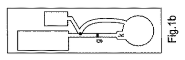
図1aに示す一実施形態において、液体サンプルを処理するための装置は、円形領域として示される、サンプル受容用の1つの領域を含む。液体を受容する能力を有する2つの独立した矩形のシンクと、各々が1つのシンクにそれぞれ連結された2つの流路と、少なくともこれら2つの流路の間の1つの連結部と、が存在する。この実施形態において、反応体は、「k」とマークされた領域の基板上に乾燥される。さらに、実施形態は、図1の「g」で示すように、少なくとも2つの方向から液体に接触するときに、液体の流れを可能にするゲートを含む。 In one embodiment shown in FIG. 1a, an apparatus for processing a liquid sample includes one region for sample reception, shown as a circular region. There are two independent rectangular sinks with the ability to receive liquid, two flow paths each connected to a single sink, and at least one connection between the two flow paths. . In this embodiment, the reactants are dried on the substrate in the area marked “k”. Furthermore, embodiments include a gate that allows liquid flow when contacting the liquid from at least two directions, as shown by “g” in FIG.
2つ以上の側方から液体に接触するときに、そのようなゲートが液体の流れのみを可能にする、ということが留意されねばならない。本発明で使用できるゲートの一例が図4に示される。本発明で使用できるゲートが図4に示されるゲートに限定されない、ということが留意されねばならない。一方側からだけ液体に接触するときに液体の流れを阻止し、かつ、2つ以上の側から液体に接触するときに液体の流れを可能にする、任意のタイプのゲートを使用することができる。 It should be noted that such a gate only allows liquid flow when contacting the liquid from more than one side. An example of a gate that can be used in the present invention is shown in FIG. It should be noted that the gates that can be used in the present invention are not limited to the gates shown in FIG. Any type of gate can be used that prevents liquid flow when contacting liquid from only one side and allows liquid flow when contacting liquid from more than one side. .
液体が図4に示される流路を左から右に流れるときに、流れが阻止され、液体が右から左に流れるときに、ゲートは両方向の流れを可能にする。右から左の液体の流れは、主流路の側方の小流路を流れ、両側から液体が一緒になることを可能にして、これによりゲートを越えて流れることを可能にする。それは、突起部の位置、距離、形態、直径、および、高さ、ならびに、小流路の幅および位置を調整することによって、対象とする液体にゲートの毛管力が適合されるときに達成することが可能である。 When liquid flows from left to right in the flow path shown in FIG. 4, the flow is blocked and when the liquid flows from right to left, the gate allows flow in both directions. The flow of liquid from right to left flows through a small channel on the side of the main channel, allowing the liquids to come together from both sides, thereby allowing them to flow over the gate. It is achieved when the capillary force of the gate is adapted to the liquid of interest by adjusting the position, distance, form, diameter, and height of the protrusion and the width and position of the small channel It is possible.
一実施形態において、ゲートは、調整済みの位置、距離、形態、直径、および、高さを有する突起部を含む。 In one embodiment, the gate includes a protrusion having an adjusted position, distance, form, diameter, and height.
別の実施形態において、ゲートは存在しない。代わりに、流路を長くすること、および/または、液体に及ぶ毛管力を小さくすることにより、流路のうちの少なくとも1つの流路の流れが残りの流路より遅くされる。 In another embodiment, there is no gate. Instead, the flow of at least one of the channels is made slower than the remaining channels by lengthening the channels and / or reducing the capillary force over the liquid.
突起部の距離、形態、直径、および、高さは、流路の少なくとも一部およびシンクのうちの1つの毛管力が他方のシンクに通じる流路と比較してより高くなるように構成される。 The distance, form, diameter, and height of the protrusion are configured such that at least a portion of the flow path and the capillary force of one of the sinks is higher than the flow path leading to the other sink. .
一実施形態において、少なくとも1つの試薬は、流路のうち少なくとも1つの流路の表面に吸着される。別の実施形態において、試薬は、最も低い毛管力を発揮する流路に吸着される。 In one embodiment, at least one reagent is adsorbed on the surface of at least one of the channels. In another embodiment, the reagent is adsorbed in the channel that exerts the lowest capillary force.
異なった毛管力を液体に及ぼす流路は、一実施形態において、異なった毛管力のために、液体毎に異なった流量を有する。 The flow paths that exert different capillary forces on the liquids, in one embodiment, have different flow rates for each liquid due to the different capillary forces.
図2の流路の交差の一実施形態は、図3に示され、異なった毛管力を形成するために異なったスペースを有する突起部の特定の実施形態から成る。 One embodiment of the flow path intersection of FIG. 2 is shown in FIG. 3 and consists of a specific embodiment of protrusions having different spaces to create different capillary forces.
図1aに示される一実施形態において、液体に異なった毛管力を及ぼす2つの異なったシンクが存在する。図1dに示される別の実施形態において、液体に異なった毛管力を及ぼす、2つの部分に分けられた1つのシンクが存在する。これらの部分の間の境界は、図1dの点線で示されている。最も高い毛管力を発揮する部分が完全に満たされるとき、液体は、作用が図1aおよび図1bの作用と同じであるように、より低い毛管力を液体に及ぼす領域に流れ始める。 In one embodiment shown in FIG. 1a, there are two different sinks that exert different capillary forces on the liquid. In another embodiment shown in FIG. 1d, there is one sink divided into two parts that exerts different capillary forces on the liquid. The boundary between these parts is indicated by the dotted line in FIG. When the portion that exerts the highest capillary force is completely filled, the liquid begins to flow into the region that exerts a lower capillary force on the liquid, so that the action is the same as in FIGS. 1a and 1b.
一実施形態において、分析ポイントに物質が吸着および/または結合される。一実施形態において、そのような物質は、少なくとも1つの分析物に結合する特性を有する。そのような物質の例として、抗体が含まれる。 In one embodiment, the object substance is adsorbed and / or bonded to the analysis points. In one embodiment, such substances have the property of binding to at least one analyte. Examples of such substances include antibodies.
一実施形態において、少なくとも1つの試薬が、少なくとも1つのフローチャネル上に吸着または乾燥される。そのような試薬は、分析に加わる任意の化学的実体または生物学的実体(chemical or biological entity)にすることができる。試薬の例として、抗体、検出可能な実体を含む抗体、他の検出可能な分子、および、分析物に対する結合能力を有する分子が含まれる。 In one embodiment, at least one reagent is adsorbed or dried on at least one flow channel. Such a reagent can be any chemical or biological entity that participates in the analysis. Examples of reagents include antibodies, antibodies that contain a detectable entity, other detectable molecules, and molecules that have the ability to bind to an analyte.
別の実施形態において、たとえば、2つ、3つ、または、それ以上の試薬が時間差を有して連続的に付加されるような多段階分析を実行することが可能である。そのような実施形態は、図1cに示されており、2つの独立した試薬kおよびk’が互いの後に加えられる。一実施形態において、少なくとも3つの異なった毛管力が液体に及ぼされ、第1の毛管力が第1のシンクを形成し、第2の毛管力が第2のシンクを形成し、第3の毛管力が第3のシンクを形成する。一実施形態において、図1cに示される異なった寸法のシンクが存在する。別の実施形態において、突起部は、異なったシンクおよび流路に関して、及ぼされる毛管力が異なるように構成される。 In another embodiment, a multi-stage analysis can be performed, for example, where two, three, or more reagents are added sequentially with a time lag. Such an embodiment is shown in FIG. 1c, and two independent reagents k and k 'are added after each other. In one embodiment, at least three different capillary forces are exerted on the liquid, the first capillary force forms a first sink, the second capillary force forms a second sink, and a third capillary The force forms a third sink. In one embodiment, there are different sized sinks shown in FIG. 1c. In another embodiment, the protrusions are configured such that the applied capillary force is different for different sinks and channels.
別の実施形態において、2つ以上の工程を含む分析を実行することが可能である。一実施形態において、3つの工程を含む複合分析が実施される。そのような分析の具体的な例として、図1cに係る装置があり、分析物に対する第1の抗体が分析ポイントに結合される。第1の工程で、サンプルが分析ポイントを通過し、分析物が表面上の第1の抗体の一部に結合される。第2の工程で、一般的な結合ユニット(binding unit)を含む第2の抗体であって、分析物に対する第2の抗体は、分析ポイントを通過する。第2の工程で、第2の抗体は、分析ポイントで第1の抗体に結合される分析物に結合する。第3の工程で、第2の抗体の一般的な結合ユニットに対する結合能力を有する検出可能な分子は、分析ポイントを通過する。第3の工程で、検出可能な分子は、抗体に結合される。この3つの工程の分析の利点は、第3の工程が全ての形式の検査に関して同一なことであり、これにより多くの異なった検査に関して一度で最適化できる。 In another embodiment, an analysis that includes two or more steps can be performed. In one embodiment, a combined analysis comprising three steps is performed. Specific examples of such an analysis, there is apparatus according to Fig. 1c, a first antibody against the analyte is coupled to the analysis points. In the first step, the sample passes through the analysis point and the analyte is bound to a portion of the first antibody on the surface. In the second step, a general coupling units (binding Unit) A including a second antibody, a second antibody against the analyte, passes through the analysis point. In the second step, the second antibody binds to an analyte that is bound to the first antibody at the analysis point. In the third step, detectable molecules that have the ability to bind the second antibody to the general binding unit pass through the analysis point. In the third step, the detectable molecule is bound to the antibody. The advantage of this three-step analysis is that the third step is the same for all types of inspection, which can be optimized at once for many different inspections.
本発明の第2の態様において、サンプルを分析する方法が提供され、上述したような装置を用いて分析が実行される。そのような方法において、好ましくは、サンプルは、サンプルを受容するための領域に対して加えられる。好ましくは、この方法は、分析の結果を読み取る工程を含む。 In a second aspect of the invention, a method for analyzing a sample is provided, and the analysis is performed using an apparatus as described above. In such a method, preferably the sample is added to an area for receiving the sample. Preferably, the method includes the step of reading the results of the analysis.
本発明の第3の態様において、上述したような装置および少なくとも1つの試薬を含む部品のキットが提供される。自由選択として、部品キットは、別のアッセイ装置を含む。そのようなアッセイ装置の例として、装置のためのホルダ、装置が挿入される計測装置、または、分析を容易にする他の装置が含まれる。一実施形態において、そのような部品キットは、少なくとも1つのパッケージを含む。他の実施形態において、部品キットは、書面による指示を含む。別の実施形態において、部品キットは、装置で計測を実行できる読み取り装置を含む。そのような読み取り装置は、分析ポイントでの計測を行うことができる。 In a third aspect of the present invention, a kit of parts comprising an apparatus as described above and at least one reagent is provided. Optionally, the component kit includes a separate assay device. Examples of such assay devices include a holder for the device, a measuring device into which the device is inserted, or other devices that facilitate analysis. In one embodiment, such a component kit includes at least one package. In other embodiments, the parts kit includes written instructions. In another embodiment, the component kit includes a reader that can perform measurements on the device. Such a reader can perform measurement at the analysis point.
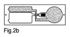
一実施形態において、サンプルを受容する領域に液体のサンプルが加えられるとき、液体は、一方の流路のゲートまで流れて行き、試薬は、サンプルによって溶かされる。それは、図2aに示される。図2において、黒い矩形は、反応体を象徴している。他方の流路において、液体は、サンプルを受容するための領域に流れ込む。サンプルは、計測が実行される分析ポイントを通り過ぎる。流路のうち1つの流路の高い毛管力のために、液体は、最大の毛管力を持つ流路に沿って流れて、より高い毛管力を持つシンクを満たす。より高い毛管力を持つシンクが完全に満たされるまでは、液体は、より低い毛管力を持つ領域に流れ込み始めることはない。第1の工程で分析ポイントを流れるサンプルの量および時間は、より高い毛管力を持つシンクを満たすことによって定められる。図2bにおいて、より高い毛管力を持つシンクが完全に満たされ、そして、サンプルは、液体により低い毛管力を及ぼす領域に流れ込み始める。 In one embodiment, when a liquid sample is added to a region that receives the sample, the liquid flows to the gate of one flow path and the reagent is dissolved by the sample. It is shown in Fig. 2a. In FIG. 2, the black rectangle symbolizes the reactant. In the other channel, the liquid flows into the area for receiving the sample. The sample passes the analysis point where the measurement is performed. Due to the high capillary force of one channel of the flow path, the liquid flows along the flow path having the largest capillary force to fill the sink with a higher capillary force. Until sink having a higher capillary force is filled completely, the liquid does not begin to flow into the area with a lower capillary force. The amount and time of the sample through the analytical point in the first step is determined by filling the sink with a higher capillary force. In FIG. 2b, a sink having a higher capillary force is filled completely, and the sample begins to flow into the region on the lower capillary force on the liquid.
次いで、液体はゲートに向かって流れ、これによってゲートの両側が液体に接触するとき、液体は両方向にゲートを横切って流れることができる。溶解した反応体を有する液体は、図2cで示されるように他方のシンクに向かって流れる。図2cには、黒い矩形で象徴された溶解した反応体が分析ポイントを通過することが示されている。図2dでは、計測が完了され、全てのシンクが完全に満たされ、かつ/または、もはや利用可能なサンプル量が無い。したがって、ゲートが開かれる前の時間は、良好に定めることができ、試薬が十分な程度に溶解され得るように時間が調節される。 The liquid then flows towards the gate, so that when both sides of the gate come into contact with the liquid, the liquid can flow across the gate in both directions. The liquid with dissolved reactants flows towards the other sink as shown in FIG. 2c. FIG. 2c shows that the dissolved reactant, symbolized by a black rectangle, passes through the analysis point. In FIG. 2d, the measurement is complete, all sinks are completely filled, and / or there is no more sample volume available. Thus, the time before the gate is opened can be well defined and the time is adjusted so that the reagent can be sufficiently dissolved.
Claims (13)
a)前記装置の表面に実質上垂直な突起部であって、高さ、直径、および、前記突起部間の距離を有し、前記表面の側方の、流体の毛管流れを発生できる、突起部と、
b)液体サンプルを受容するための少なくとも1つの領域と、
c)i)前記液体を受容するための能力を有し、異なった毛管力をそれぞれが前記液体サンプルに及ぼす少なくとも2つの部分を有する、少なくとも1つのシンク、およびii)異なった毛管力をそれぞれが前記液体サンプルに及ぼす少なくとも2つの異なったシンク、から選択された一方と、
d)液体サンプルを受容するための前記少なくとも1つの領域および前記少なくとも1つのシンクを連結し、少なくとも2つの異なった毛管力を前記液体サンプルに及ぼす少なくとも2つの流路であって、最も高い毛管力を及ぼす前記流路は、最も高い毛管力を及ぼす、前記シンクまたは前記部分に連結される、流路と、
e)前記少なくとも2つの流路の間の少なくとも1つの連結部と、
を含む、装置。 In an apparatus for processing a liquid sample,
a) a protrusion substantially perpendicular to the surface of the device, the protrusion having a height, a diameter and a distance between the protrusions and capable of generating a capillary flow of fluid laterally of the surface And
b) at least one region for receiving a liquid sample;
have the capability for receiving the c) i) said liquid, respectively capillary force becomes different have at least two portions on the liquid sample, at least one sink, and ii) different capillary forces, respectively One selected from at least two different sinks that affect the liquid sample ;
d) at least two flow paths connecting the at least one region for receiving a liquid sample and the at least one sink and exerting at least two different capillary forces on the liquid sample , the highest capillary force The flow path that is coupled to the sink or the portion that exerts the highest capillary force; and
e) at least one connection between the at least two flow paths;
Including the device.
前記流路のうちの少なくとも1つは、少なくとも1つのゲートを含み、該ゲートが、少なくとも2つの方向から液体に接触するときに、液体サンプルの流れを可能にする、装置。 The apparatus of claim 1 .
An apparatus wherein at least one of the flow paths includes at least one gate that allows liquid sample flow when contacting the liquid from at least two directions.
前記ゲートは、前記装置の前記表面に実質上垂直な突起部をさらに含む、装置。 The apparatus of claim 2 .
The device, wherein the gate further comprises a protrusion substantially perpendicular to the surface of the device.
前記流路のうちの少なくとも1つには、少なくとも1つの試薬が吸着される、装置。 The apparatus according to any one of claims 1 to 3
An apparatus in which at least one reagent is adsorbed in at least one of the flow paths.
前記液体サンプルに最も低い毛管力を及ぼす前記流路には、少なくとも1つの試薬が吸着される、装置。 The device according to any one of claims 1 to 4 ,
An apparatus in which at least one reagent is adsorbed in the flow path that exerts the lowest capillary force on the liquid sample .
前記少なくとも2つの流路は、前記液体サンプルに関して異なった流量を有する、装置。 In the apparatus of any one of Claims 1-5 ,
The apparatus, wherein the at least two flow paths have different flow rates with respect to the liquid sample .
前記装置は、少なくとも3つの異なった毛管力を前記液体サンプルに及ぼす、装置。 In the apparatus of any one of Claims 1-6 ,
The device exerts at least three different capillary forces on the liquid sample .
前記装置は、少なくとも2つの異なった試薬をさらに含む、装置。 The apparatus of claim 7 .
The apparatus further comprises at least two different reagents.
請求項1〜8のいずれか1項に記載の装置が使用され、
前記液体サンプルは、液体サンプルを受容するための前記少なくとも1つの領域に加えられることを特徴とする、方法。 In a method for analyzing a sample:
A device according to any one of claims 1 to 8 is used,
The method, wherein the liquid sample is added to the at least one region for receiving a liquid sample.
前記装置から結果が読み取られる、方法。 The method of claim 9 , wherein
A method wherein a result is read from the device.
請求項1〜8のいずれか1項に記載の装置と、
少なくとも1つの試薬と、
を含む、部品のキット。 In the kit of parts,
An apparatus according to any one of claims 1 to 8 ,
At least one reagent;
Including parts kit.
分析装置、
をさらに含む、部品のキット。 The kit of parts according to claim 11 ,
Analysis equipment,
A kit of parts further comprising:
前記装置での計測を実行することが可能である少なくとも1つの読み取り装置、
をさらに含む、部品のキット。 In a kit of parts according to any one of claims 11-12,
At least one reading device capable of performing measurements on said device;
A kit of parts further comprising:
Applications Claiming Priority (5)
| Application Number | Priority Date | Filing Date | Title |
|---|---|---|---|
| US92379807P | 2007-04-16 | 2007-04-16 | |
| SE0700930-1 | 2007-04-16 | ||
| US60/923,798 | 2007-04-16 | ||
| SE0700930A SE529978C2 (en) | 2007-04-16 | 2007-04-16 | Analysis device for liquid samples, e.g. patient samples, includes flow paths between sample receiving and holding areas capable of exerting different capillary forces |
| PCT/SE2008/050424 WO2008127191A1 (en) | 2007-04-16 | 2008-04-15 | Device for handling liquid samples |
Publications (3)
| Publication Number | Publication Date |
|---|---|
| JP2010525319A JP2010525319A (en) | 2010-07-22 |
| JP2010525319A5 JP2010525319A5 (en) | 2013-11-21 |
| JP5425757B2 true JP5425757B2 (en) | 2014-02-26 |
Family
ID=38935813
Family Applications (1)
| Application Number | Title | Priority Date | Filing Date |
|---|---|---|---|
| JP2010504015A Active JP5425757B2 (en) | 2007-04-16 | 2008-04-15 | Apparatus for processing liquid samples |
Country Status (6)
| Country | Link |
|---|---|
| EP (1) | EP2134472A4 (en) |
| JP (1) | JP5425757B2 (en) |
| CN (1) | CN101678355B (en) |
| CA (1) | CA2683920C (en) |
| SE (1) | SE529978C2 (en) |
| WO (1) | WO2008127191A1 (en) |
Families Citing this family (7)
| Publication number | Priority date | Publication date | Assignee | Title |
|---|---|---|---|---|
| WO2011003689A2 (en) * | 2009-07-07 | 2011-01-13 | Boehringer Ingelheim Microparts Gmbh | Plasma separation reservoir |
| EP2618153B1 (en) * | 2012-01-20 | 2015-03-18 | Ortho-Clinical Diagnostics, Inc. | Controlling fluid flow through an assay device |
| BR102013001328A2 (en) * | 2012-01-20 | 2015-05-12 | Ortho Clinical Diagnostics Inc | Teaching device having uniform flow near corners |
| JP6278772B2 (en) * | 2014-03-19 | 2018-02-14 | テルモ株式会社 | Blood glucose measurement chip |
| EP3226003A4 (en) * | 2014-11-28 | 2018-06-20 | Toyo Seikan Group Holdings, Ltd. | Micro liquid transfer structure and analysis device |
| CN107219170B (en) * | 2017-07-24 | 2023-09-19 | 苏州鼎实医疗科技有限公司 | Reagent tablet |
| WO2022058470A1 (en) * | 2020-09-17 | 2022-03-24 | Katholieke Universiteit Leuven | Activation and pressure balancing mechanism |
Family Cites Families (19)
| Publication number | Priority date | Publication date | Assignee | Title |
|---|---|---|---|---|
| JPH0610900A (en) * | 1992-04-27 | 1994-01-21 | Canon Inc | Method and device for moving liquid and measuring device utilizing these method and device |
| US6156270A (en) * | 1992-05-21 | 2000-12-05 | Biosite Diagnostics, Inc. | Diagnostic devices and apparatus for the controlled movement of reagents without membranes |
| JP3213566B2 (en) * | 1996-04-26 | 2001-10-02 | アークレイ株式会社 | Sample analysis tool, sample analysis method and sample analyzer using the same |
| AU763497B2 (en) * | 1998-10-13 | 2003-07-24 | Biomicro Systems, Inc. | Fluid circuit components based upon passive fluid dynamics |
| US6571651B1 (en) * | 2000-03-27 | 2003-06-03 | Lifescan, Inc. | Method of preventing short sampling of a capillary or wicking fill device |
| SE0201738D0 (en) * | 2002-06-07 | 2002-06-07 | Aamic Ab | Micro-fluid structures |
| KR100444751B1 (en) * | 2002-11-11 | 2004-08-16 | 한국전자통신연구원 | Device of Controlling Fluid using Surface Tension |
| US20060043284A1 (en) * | 2002-11-29 | 2006-03-02 | Nec Corporation | Micro chip, liquid feeding method using the micro chip, and mass analyzing system |
| DE10302720A1 (en) * | 2003-01-23 | 2004-08-05 | Steag Microparts Gmbh | Microfluidic switch for stopping the flow of fluid during a time interval |
| EP1525919A1 (en) * | 2003-10-23 | 2005-04-27 | F. Hoffmann-La Roche Ag | Flow triggering device |
| EP1525916A1 (en) * | 2003-10-23 | 2005-04-27 | F. Hoffmann-La Roche Ag | Flow triggering device |
| CN1238713C (en) * | 2003-11-01 | 2006-01-25 | 浙江大学 | Integrated minityped magnetic pump model capillary electrophoresis chip |
| GB2410086A (en) * | 2004-01-14 | 2005-07-20 | British Biocell Internat Ltd | Assay devices having flow block(s) to determine flow of liquids |
| JP4123275B2 (en) * | 2004-02-06 | 2008-07-23 | 日本電気株式会社 | Control structure, separation device and gradient forming device, and microchip using them |
| SE0400662D0 (en) * | 2004-03-24 | 2004-03-24 | Aamic Ab | Assay device and method |
| SE527036C2 (en) * | 2004-06-02 | 2005-12-13 | Aamic Ab | Controlled flow analysis device and corresponding procedure |
| US7682817B2 (en) * | 2004-12-23 | 2010-03-23 | Kimberly-Clark Worldwide, Inc. | Microfluidic assay devices |
| AU2006217719A1 (en) * | 2005-02-25 | 2006-08-31 | Alere Switzerland Gmbh | Fluidic gating device |
| WO2006098370A1 (en) * | 2005-03-16 | 2006-09-21 | Nec Corporation | Delay circuit with mechanism for adjusting effective passing time of channel, microchip, and method for fabricating the same |
-
2007
- 2007-04-16 SE SE0700930A patent/SE529978C2/en unknown
-
2008
- 2008-04-15 JP JP2010504015A patent/JP5425757B2/en active Active
- 2008-04-15 EP EP08741914.9A patent/EP2134472A4/en not_active Ceased
- 2008-04-15 CN CN200880012452.4A patent/CN101678355B/en active Active
- 2008-04-15 CA CA2683920A patent/CA2683920C/en not_active Expired - Fee Related
- 2008-04-15 WO PCT/SE2008/050424 patent/WO2008127191A1/en active Application Filing
Also Published As
| Publication number | Publication date |
|---|---|
| JP2010525319A (en) | 2010-07-22 |
| CN101678355A (en) | 2010-03-24 |
| CA2683920A1 (en) | 2008-10-23 |
| SE0700930L (en) | 2008-01-22 |
| WO2008127191A1 (en) | 2008-10-23 |
| SE529978C2 (en) | 2008-01-22 |
| EP2134472A4 (en) | 2014-10-01 |
| EP2134472A1 (en) | 2009-12-23 |
| CN101678355B (en) | 2012-11-14 |
| CA2683920C (en) | 2016-05-31 |
Similar Documents
| Publication | Publication Date | Title |
|---|---|---|
| JP5425757B2 (en) | Apparatus for processing liquid samples | |
| US9050595B2 (en) | Assay devices with integrated sample dilution and dilution verification and methods of using same | |
| US9795697B2 (en) | Liquid containment for integrated assays | |
| Mohammed et al. | Autonomous capillary microfluidic system with embedded optics for improved troponin I cardiac biomarker detection | |
| JP6013519B2 (en) | Microfluidic device based on integrated electrochemical immunoassay and its substrate | |
| WO2012081361A1 (en) | Analysis apparatus and analysis method | |
| JP2006208388A (en) | Apparatus and method for inspecting sample solution | |
| JP5013423B2 (en) | Microchip | |
| CA2720839C (en) | Assay method and device for analytes in a sample | |
| WO2012075256A2 (en) | Sample metering device and assay device with integrated sample dilution | |
| Lutz et al. | A fully integrated microfluidic platform for highly sensitive analysis of immunochemical parameters | |
| JP5137007B2 (en) | Microchip | |
| WO2012075258A2 (en) | Ratiometric immunoassay method and blood testing device | |
| JP4987592B2 (en) | Microfluidic chip | |
| EP3186634B1 (en) | Test strip assembly | |
| JP2008101984A (en) | Chip having measurement section and method of measuring liquid sample using the chip | |
| US20110070664A1 (en) | Integrated Microfluidic Device for Serum Biomarker Quantitation using Either Standard Addition or a Calibration Curve | |
| US20230147248A1 (en) | Liquid handling device | |
| JP2009085818A (en) | Liquid reagent built-in type microchip | |
| JP6738066B2 (en) | Extraction filter and immunochromatographic analysis kit including the same | |
| JP2023510552A (en) | Centrifugal microfluidic device with blocking chamber and detection chamber | |
| KR20210152247A (en) | Method for manufacturing lateral flow analysis device | |
| KR20220142137A (en) | Target protein concentration method using acoustic energy and quantitative measurement method of concentrated target protein | |
| JP2024517683A (en) | Biosensors | |
| JP2003194818A (en) | Specific binding analyzing method and device used therefor |
Legal Events
| Date | Code | Title | Description |
|---|---|---|---|
| RD04 | Notification of resignation of power of attorney |
Free format text: JAPANESE INTERMEDIATE CODE: A7424 Effective date: 20100726 |
|
| A621 | Written request for application examination |
Free format text: JAPANESE INTERMEDIATE CODE: A621 Effective date: 20110411 |
|
| RD04 | Notification of resignation of power of attorney |
Free format text: JAPANESE INTERMEDIATE CODE: A7424 Effective date: 20111202 |
|
| A977 | Report on retrieval |
Free format text: JAPANESE INTERMEDIATE CODE: A971007 Effective date: 20120809 |
|
| A131 | Notification of reasons for refusal |
Free format text: JAPANESE INTERMEDIATE CODE: A131 Effective date: 20120814 |
|
| A601 | Written request for extension of time |
Free format text: JAPANESE INTERMEDIATE CODE: A601 Effective date: 20121114 |
|
| A602 | Written permission of extension of time |
Free format text: JAPANESE INTERMEDIATE CODE: A602 Effective date: 20121121 |
|
| A601 | Written request for extension of time |
Free format text: JAPANESE INTERMEDIATE CODE: A601 Effective date: 20121214 |
|
| A602 | Written permission of extension of time |
Free format text: JAPANESE INTERMEDIATE CODE: A602 Effective date: 20121221 |
|
| A601 | Written request for extension of time |
Free format text: JAPANESE INTERMEDIATE CODE: A601 Effective date: 20130111 |
|
| A602 | Written permission of extension of time |
Free format text: JAPANESE INTERMEDIATE CODE: A602 Effective date: 20130121 |
|
| A524 | Written submission of copy of amendment under article 19 pct |
Free format text: JAPANESE INTERMEDIATE CODE: A524 Effective date: 20130214 |
|
| A131 | Notification of reasons for refusal |
Free format text: JAPANESE INTERMEDIATE CODE: A131 Effective date: 20130319 |
|
| A601 | Written request for extension of time |
Free format text: JAPANESE INTERMEDIATE CODE: A601 Effective date: 20130619 |
|
| A602 | Written permission of extension of time |
Free format text: JAPANESE INTERMEDIATE CODE: A602 Effective date: 20130626 |
|
| A601 | Written request for extension of time |
Free format text: JAPANESE INTERMEDIATE CODE: A601 Effective date: 20130719 |
|
| A602 | Written permission of extension of time |
Free format text: JAPANESE INTERMEDIATE CODE: A602 Effective date: 20130726 |
|
| A601 | Written request for extension of time |
Free format text: JAPANESE INTERMEDIATE CODE: A601 Effective date: 20130819 |
|
| A602 | Written permission of extension of time |
Free format text: JAPANESE INTERMEDIATE CODE: A602 Effective date: 20130826 |
|
| A521 | Request for written amendment filed |
Free format text: JAPANESE INTERMEDIATE CODE: A523 Effective date: 20130919 |
|
| A524 | Written submission of copy of amendment under article 19 pct |
Free format text: JAPANESE INTERMEDIATE CODE: A524 Effective date: 20130919 |
|
| TRDD | Decision of grant or rejection written | ||
| A01 | Written decision to grant a patent or to grant a registration (utility model) |
Free format text: JAPANESE INTERMEDIATE CODE: A01 Effective date: 20131029 |
|
| A61 | First payment of annual fees (during grant procedure) |
Free format text: JAPANESE INTERMEDIATE CODE: A61 Effective date: 20131127 |
|
| R150 | Certificate of patent or registration of utility model |
Free format text: JAPANESE INTERMEDIATE CODE: R150 Ref document number: 5425757 Country of ref document: JP Free format text: JAPANESE INTERMEDIATE CODE: R150 |
|
| R250 | Receipt of annual fees |
Free format text: JAPANESE INTERMEDIATE CODE: R250 |
|
| R250 | Receipt of annual fees |
Free format text: JAPANESE INTERMEDIATE CODE: R250 |
|
| R250 | Receipt of annual fees |
Free format text: JAPANESE INTERMEDIATE CODE: R250 |
|
| S111 | Request for change of ownership or part of ownership |
Free format text: JAPANESE INTERMEDIATE CODE: R313111 |
|
| R250 | Receipt of annual fees |
Free format text: JAPANESE INTERMEDIATE CODE: R250 |
|
| R371 | Transfer withdrawn |
Free format text: JAPANESE INTERMEDIATE CODE: R371 |
|
| R250 | Receipt of annual fees |
Free format text: JAPANESE INTERMEDIATE CODE: R250 |
|
| R250 | Receipt of annual fees |
Free format text: JAPANESE INTERMEDIATE CODE: R250 |
|
| R250 | Receipt of annual fees |
Free format text: JAPANESE INTERMEDIATE CODE: R250 |
|
| R250 | Receipt of annual fees |
Free format text: JAPANESE INTERMEDIATE CODE: R250 |