JP5424581B2 - Shape measurement method for combining partial measurements - Google Patents
Shape measurement method for combining partial measurements Download PDFInfo
- Publication number
- JP5424581B2 JP5424581B2 JP2008149366A JP2008149366A JP5424581B2 JP 5424581 B2 JP5424581 B2 JP 5424581B2 JP 2008149366 A JP2008149366 A JP 2008149366A JP 2008149366 A JP2008149366 A JP 2008149366A JP 5424581 B2 JP5424581 B2 JP 5424581B2
- Authority
- JP
- Japan
- Prior art keywords
- shape
- measurement data
- parameter
- partial measurement
- error
- Prior art date
- Legal status (The legal status is an assumption and is not a legal conclusion. Google has not performed a legal analysis and makes no representation as to the accuracy of the status listed.)
- Active
Links
Images


Classifications
-
- G—PHYSICS
- G01—MEASURING; TESTING
- G01B—MEASURING LENGTH, THICKNESS OR SIMILAR LINEAR DIMENSIONS; MEASURING ANGLES; MEASURING AREAS; MEASURING IRREGULARITIES OF SURFACES OR CONTOURS
- G01B21/00—Measuring arrangements or details thereof, where the measuring technique is not covered by the other groups of this subclass, unspecified or not relevant
- G01B21/20—Measuring arrangements or details thereof, where the measuring technique is not covered by the other groups of this subclass, unspecified or not relevant for measuring contours or curvatures, e.g. determining profile
-
- G—PHYSICS
- G01—MEASURING; TESTING
- G01B—MEASURING LENGTH, THICKNESS OR SIMILAR LINEAR DIMENSIONS; MEASURING ANGLES; MEASURING AREAS; MEASURING IRREGULARITIES OF SURFACES OR CONTOURS
- G01B21/00—Measuring arrangements or details thereof, where the measuring technique is not covered by the other groups of this subclass, unspecified or not relevant
- G01B21/02—Measuring arrangements or details thereof, where the measuring technique is not covered by the other groups of this subclass, unspecified or not relevant for measuring length, width, or thickness
- G01B21/04—Measuring arrangements or details thereof, where the measuring technique is not covered by the other groups of this subclass, unspecified or not relevant for measuring length, width, or thickness by measuring coordinates of points
- G01B21/045—Correction of measurements
-
- G—PHYSICS
- G01—MEASURING; TESTING
- G01M—TESTING STATIC OR DYNAMIC BALANCE OF MACHINES OR STRUCTURES; TESTING OF STRUCTURES OR APPARATUS, NOT OTHERWISE PROVIDED FOR
- G01M11/00—Testing of optical apparatus; Testing structures by optical methods not otherwise provided for
- G01M11/005—Testing of reflective surfaces, e.g. mirrors
-
- G—PHYSICS
- G01—MEASURING; TESTING
- G01M—TESTING STATIC OR DYNAMIC BALANCE OF MACHINES OR STRUCTURES; TESTING OF STRUCTURES OR APPARATUS, NOT OTHERWISE PROVIDED FOR
- G01M11/00—Testing of optical apparatus; Testing structures by optical methods not otherwise provided for
- G01M11/02—Testing optical properties
- G01M11/0242—Testing optical properties by measuring geometrical properties or aberrations
- G01M11/025—Testing optical properties by measuring geometrical properties or aberrations by determining the shape of the object to be tested
Description
本発明は複数の接触式プローブで計測した部分測定データを合成し、全体の形状を得る測定技術に関する。この技術は小さな測定領域しか持たない装置で大型の光学素子を測定するのに応用される。この技術をスティッチと呼ぶ場合もある。 The present invention relates to a measurement technique for synthesizing partial measurement data measured by a plurality of contact probes and obtaining an overall shape. This technique is applied to measuring a large optical element with an apparatus having only a small measurement area. This technique is sometimes called stitching.
まず、本明細書と引用文献で使っている用語との関係について説明しておく。 First, the relationship between the present specification and terms used in the cited document will be described.
「部分測定技術」は「スティッチ技術」と同じ意味で使用する。 “Partial measurement technique” is used interchangeably with “stitch technique”.
複数の部分測定データに関し、「重なる領域」と「オーバーラップ領域」は同じ意味で使用する。 With respect to a plurality of partial measurement data, “overlapping area” and “overlap area” are used interchangeably.
複数の部分測定データに関し、「重なる領域での各測定データの差異」と「ミスマッチ」は同じ意味で使用する。 Regarding a plurality of partial measurement data, “difference between measurement data in overlapping areas” and “mismatch” are used interchangeably.
この技術分野は主に干渉計を用いた形状測定を通じて発展してきた技術である。 This technical field has been developed mainly through shape measurement using an interferometer.
本発明は座標測定装置にも応用展開することも可能な発明であるので、そこで、まずは干渉計による干渉計測と座標測定装置による測定との違いを説明する。 Since the present invention can also be applied to a coordinate measuring apparatus, first, the difference between interference measurement using an interferometer and measurement using a coordinate measuring apparatus will be described.
干渉計測とは、被測定物の形状を反映した測定波面と、人為的に作成した参照波面とで発生する干渉縞をカメラ等で測定し、測定した干渉縞から形状を求める測定法である。 Interference measurement is a measurement method in which an interference fringe generated between a measurement wavefront reflecting the shape of an object to be measured and an artificially created reference wavefront is measured with a camera or the like, and the shape is obtained from the measured interference fringe.
この場合、複数の測定データは、ほぼ同じ参照波面からの差である。言い換えると、各測定データは参照波面という共通オフセットからの偏差を表している。しかもその偏差は干渉縞が観察できなければならないという要求から原理的に小さい。測定領域をいくつかの領域に区切って互いにオーバーラップするように測定したとき、そのオーバーラップ領域の測定データ間の差が小さいのが特徴である。 In this case, the plurality of measurement data are differences from substantially the same reference wavefront. In other words, each measurement data represents a deviation from a common offset called a reference wavefront. Moreover, the deviation is small in principle because of the requirement that the interference fringes must be observable. When the measurement area is divided into several areas and measured so as to overlap each other, the difference between the measurement data in the overlap area is small.
例えば可視光を用いる場合、干渉縞の間隔はサブミクロンとなり、測定データ間の差は大きい場合でもミクロンレベルである。一般に部分測定、すなわちスティッチが必要な被測定物のサイズ、例えば直径1mのレンズ、と比較すると、この値は小さいと言える。 For example, when using visible light, the interval between interference fringes is submicron, and even if the difference between the measurement data is large, it is on the micron level. In general, it can be said that this value is small compared with the size of an object to be measured that requires partial measurement, that is, a lens having a diameter of 1 m, for example.
まとめると、干渉計測の場合は、部分測定データの差、すなわちミスマッチが原理的に小さいという特徴がある。 In summary, in the case of interference measurement, there is a characteristic that a difference in partial measurement data, that is, a mismatch is small in principle.
一方、座標測定装置の測定データは、被測定物表面上の点を表す3次元位置の集合である。例えば、接触式プローブを用いた座標測定装置の場合は、プローブの先端を被測定物表面に接触させ、そのプローブ先端の3次元位置を得る。そして接触式プローブを被測定物表面上で走査して3次元位置のデータを連続的に得ることで被測定物の表面形状を測定する。
その際にオーバーラップ領域での複数の測定データ間の差は、装置の位置姿勢誤差や被測定物の取り付け誤差の影響を受ける。
On the other hand, the measurement data of the coordinate measuring device is a set of three-dimensional positions representing points on the surface of the object to be measured. For example, in the case of a coordinate measuring apparatus using a contact probe, the tip of the probe is brought into contact with the surface of the object to be measured, and the three-dimensional position of the probe tip is obtained. Then, the surface shape of the object to be measured is measured by scanning the contact type probe on the surface of the object to be measured and continuously obtaining three-dimensional position data.
At this time, the difference between the plurality of measurement data in the overlap region is influenced by the position / orientation error of the apparatus and the attachment error of the object to be measured.
一般的に、6自由度あるこれらの誤差を小さくすることは、非常に高い設置精度が要求されるため困難である。 Generally, it is difficult to reduce these errors having six degrees of freedom because very high installation accuracy is required.
その結果、例えば先ほどの1mサイズのレンズの場合、オーバーラップ領域での測定データ間の差は1mmを超えても不思議ではない。 As a result, for example, in the case of the lens of 1 m size as described above, it is not surprising that the difference between the measurement data in the overlap region exceeds 1 mm.
また、干渉計の時に考慮した参照波面のような、各測定データから差し引ける共通の形状も存在しないので、測定データの値は干渉計の場合に比べて大きい。 Further, since there is no common shape that can be subtracted from each measurement data, such as the reference wavefront considered in the case of the interferometer, the value of the measurement data is larger than that of the interferometer.
まとめると、座標測定装置の場合は、部分測定データの差、すなわちミスマッチが干渉計に比較してケタ違いに大きいという特徴がある。 In summary, the coordinate measuring apparatus has a feature that the difference in partial measurement data, that is, the mismatch is larger than that of the interferometer.
部分測定データをつなぎ合わせて全体形状を合成するスティッチ技術の中心は測定データを接続する計算方法である。
この計算方法は次のように2つのステップに簡略化して考えることができる。
ステップ1 複数の部分測定データを、パラメータを使って変換する
ステップ2 変換したデータを重ね合わせ、合成して全体の測定データを得る
ステップ2はデータを補間して平均すれば重ね合わせて合成することができる。
しかしステップ1の変換方法は無数に存在するため、いかに最適な変換を行うかがスティッチ技術の良し悪しを決めると言える。
The center of stitch technology that combines partial measurement data and synthesizes the entire shape is a calculation method that connects measurement data.
This calculation method can be considered in a simplified manner in two steps as follows.
However, since there are an infinite number of conversion methods in
一般的には、変換方法を記述するパラメータと評価関数とを定義し、その評価関数が最適になるようにパラメータを調節することが行われている。 Generally, a parameter that describes a conversion method and an evaluation function are defined, and the parameters are adjusted so that the evaluation function is optimized.
以上が部分測定を合成する技術の概要である。 The above is an overview of the technique for combining partial measurements.
現在、この技術分野で最良の答えは見つかっていないので様々な方法が提案されている。この技術の特徴は、次に示す2つのポイントに着目するとそれぞれの相違が明らかになる。
1 評価関数と、パラメータをどのように定義するか
2 最適化問題をどのように解くのか
Currently, the best answer in this technical field has not been found, so various methods have been proposed. The differences between the features of this technology become clear when focusing on the following two points.
1 How to define the evaluation function and
次に図12に示し、特許文献1および特許文献2に開示されている従来技術を、上記ポイントに着目しながら説明する。
Next, the prior art shown in FIG. 12 and disclosed in
この特許文献では、次のような評価関数を提案している。
「パラメータを直線状に組み合わせることを通じて前記オーバーラップ領域内の前記データマップの各々からデータの適合外れ」、すなわち、パラメータの線形結合で表現したミスマッチを評価関数としている。
また、この特許文献では、評価関数の最適化方法として、全パラメータを同時に変化させて、この評価関数を最小にする方法を提案している。
In this patent document, the following evaluation function is proposed.
The evaluation function is “mismatched data from each of the data maps in the overlap region by combining parameters linearly”, that is, a mismatch expressed by a linear combination of parameters.
Further, this patent document proposes a method for minimizing this evaluation function by simultaneously changing all parameters as a method for optimizing the evaluation function.
また、図13に示し、特許文献3に開示されている第2の従来技術を説明する。
この方法は、被測定物に目印を設ける方法である。
この特許文献では、ミスマッチを評価関数として提案している。
この特許文献では、評価関数の最適化法として、まず目印をあわせた後で、ミスマッチを最小にする方法を提案している。
Further, the second prior art shown in FIG. 13 and disclosed in
This method is a method of providing a mark on the object to be measured.
In this patent document, mismatch is proposed as an evaluation function.
In this patent document, as a method for optimizing an evaluation function, a method for minimizing a mismatch after first matching a mark is proposed.
また、座標測定装置の構成については、例えば特許文献4に開示され、図14に示したものが知られている。接触式のプローブ30を光学素子や金型などの被測定物6の表面に押し当てながら走査し、その時のプローブの3次元座標位置を測定する装置である。
本発明の課題を述べる前にまず、本明細書における記号のつけかたについて説明する。
部分測定データをAと表記する。
部分測定データは複数あるので、それぞれを区別するため、右上肩に数字をつける。
この数字は測定番号を表している。例えばA1,A2は2つの部分測定データである。
部分測定データは測定点の集合である。各要素を区別する場合には、右下に数字をつける。
この数字は測定点番号を表している。
例えばA1データの第m番目の測定点はA1 mと表す。
Before describing the problem of the present invention, first, how to add symbols in this specification will be described.
Partial measurement data is denoted as A.
Since there are a plurality of partial measurement data, a number is attached to the upper right shoulder to distinguish each data.
This number represents the measurement number. For example, A 1 and A 2 are two partial measurement data.
Partial measurement data is a set of measurement points. When distinguishing each element, put a number in the lower right.
This number represents the measurement point number.
For example the m-th measurement point A 1 data are expressed as A 1 m.
従来技術は、複数の部分測定を図12に示したように互いに重なり合う領域で行い、この重なり合う領域の測定データの差、すなわちミスマッチが最小になるようにパラメータを最適化する。 In the conventional technique, a plurality of partial measurements are performed in areas that overlap each other as shown in FIG. 12, and the parameters are optimized so that the difference between the measurement data in the overlapping areas, that is, mismatch is minimized.
背景技術の節でも述べたがこの従来のスティッチ技術は干渉計をベースに発展してきた。これを座標測定装置に展開する場合、次に示す未解決の新しい課題が発生する。
別の言い方をすると、測定データ間の差が従来に比べてケタ違いに大きな場合、次に示す深刻な課題が新たに発生する。
As described in the background section, this conventional stitch technique has been developed based on an interferometer. When this is developed in a coordinate measuring device, the following unsolved new problems occur.
In other words, when the difference between the measurement data is larger than the conventional one, the following serious problem newly occurs.
(1) オーバーラップ領域を高精度に決定できないので精度が悪い
図2を用いて説明する。被測定物の部分測定データを同図の上段(a)に示す。
説明を簡単にするため、測定装置の誤差は考えない。また、2つの断面データを接続する場合について説明する。
(1) Since the overlap region cannot be determined with high accuracy, the accuracy is poor. The partial measurement data of the object to be measured is shown in the upper part (a) of FIG.
To simplify the explanation, the error of the measuring device is not considered. A case where two cross-section data are connected will be described.
A1,A2は2つの部分測定データである。このデータは、被測定物の位置姿勢をずらした形として表現できる。この位置姿勢のずれはセッティング誤差と呼んでおり、被測定物を装置にセットするときに発生する誤差である。このセッティング誤差を補正するために座標変換T1,T2を用いる。座標変換は一般に6自由度(XYZの平行移動と、XYZ軸回りの回転移動)が考えられる。この座標変換を行った結果を同図の中段(b)に示す。ここで、部分測定データAnを座標変換した形状をBn=Tn(An)と表現する。nは測定の番号である。また、図中2はオーバーラップ領域である。 A 1 and A 2 are two partial measurement data. This data can be expressed as a form in which the position and orientation of the object to be measured are shifted. This deviation in position and orientation is called a setting error, and is an error that occurs when the object to be measured is set in the apparatus. In order to correct this setting error, coordinate transformations T 1 and T 2 are used. The coordinate transformation is generally considered to have six degrees of freedom (XYZ parallel movement and rotational movement about the XYZ axes). The result of this coordinate transformation is shown in the middle part (b) of FIG. Here, representing the partial measurement data A n coordinate transformation shape with B n = T n (A n ). n is the number of the measurement. In the figure, 2 is an overlap region.
この時、従来技術ではオーバーラップ領域2でのB1とB2との差、すなわちミスマッチが小さくなるように座標変換T1,T2を最適化する。
In this case, the difference between the prior art and B 1 and B 2 in the
この図では説明のために、B1とB2はわざと上下にずらして描いている。 In this figure, B 1 and B 2 are intentionally shifted up and down for the purpose of explanation.
ところが、オーバーラップ領域でミスマッチが小さくなる場所はひとつではない。 However, there is not one place where mismatches are reduced in the overlap region.
同図(c)で示すようにオーバーラップ領域2の大きさを変えれば様々な場所でミスマッチを小さくできる。
If the size of the
そして、B1とB2をつなぎ合わせた全体形状は(b)図と(c)図を比較すれば明らかなようにまったく異なったものとなる。つまり従来技術を座標測定装置に適用するとオーバーラップ領域を決定できないため測定精度が悪い。 The overall shape obtained by connecting B 1 and B 2 is completely different as is apparent from the comparison of FIGS. In other words, when the conventional technique is applied to the coordinate measuring apparatus, the overlapping region cannot be determined, so that the measurement accuracy is poor.
一般的に、被測定物が非球面形状の場合、2つの形状がフィットする場所は唯一に決定できるはずである。しかし測定領域がオーバーラップする狭い領域で考えると、どんな非球面形状でも非球面量が小さくなる。つまり球面に近づいてしまうため、オーバーラップ領域を決定する誤差が大きい。その結果、測定精度が悪い。 Generally, when the object to be measured has an aspherical shape, the place where the two shapes fit should be uniquely determined. However, when considering a narrow region where the measurement regions overlap, the amount of aspherical surface becomes small for any aspherical shape. That is, since it approaches a spherical surface, the error for determining the overlap region is large. As a result, measurement accuracy is poor.
この問題は次に説明する理由により、干渉計の場合には小さな問題だったが、座標測定装置の場合は大変重要になる新しい課題である。 This problem is a small problem in the case of an interferometer for the following reason, but is a new problem that becomes very important in the case of a coordinate measuring apparatus.
干渉計の場合のようにミスマッチがもともと小さい場合、座標変換Tnによる測定データの移動量も小さい。 If mismatch as in the case of the interferometer is originally small, the amount of movement of the measurement data obtained by the coordinate transformation T n is small.
その結果、オーバーラップする領域の変化量も小さい。従って全体形状への影響も小さくなり、わずかな測定精度の悪化ですむ。 As a result, the amount of change in the overlapping region is small. Therefore, the influence on the overall shape is reduced, and only a slight deterioration in measurement accuracy is required.
しかし、座標測定装置の場合は、ミスマッチがケタ違いに大きいので、座標変換Tnによる測定データの移動量が大きい。従ってオーバーラップする領域が大きく変化するため、全体形状への影響が大きい。 However, in the case of the coordinate measuring device, since a mismatch is large of magnitude, a large amount of movement of the measurement data obtained by the coordinate transformation T n. Therefore, since the overlapping area changes greatly, the influence on the overall shape is great.
例えば直径1mのレンズを測定する時を考える。干渉計の場合には干渉縞を観察できなければ成り立たないので、ミスマッチはミクロンオーダーである。ところが座標測定装置の場合には1mのレンズを装置にセットする時の位置ずれが1mm以上あっても不思議ではなく、ミスマッチも同じオーダー、すなわちミリメートルオーダーとケタ違いに大きい。 For example, consider the case of measuring a lens having a diameter of 1 m. In the case of an interferometer, the mismatch is not possible unless interference fringes can be observed, so the mismatch is on the order of microns. However, in the case of a coordinate measuring apparatus, it is not surprising that a positional deviation of 1 mm or more when a 1-meter lens is set in the apparatus is not surprising, and the mismatch is large in the same order, that is, in the order of millimeters.
以上、従来技術ではオーバーラップ領域を高精度に決定することができないために、測定精度が悪い。要するに、部分測定データが二次元データで各々のミスマッチが小さい干渉計測と、部分測定データが三次元データでミスマッチが大きい座標測定装置とは、大きく異なる。たとえ被測定物が非球面であってもこの課題は解消されない。 As described above, the conventional technique cannot determine the overlap region with high accuracy, and therefore the measurement accuracy is poor. In short, the interferometric measurement in which the partial measurement data is two-dimensional data and each mismatch is small is greatly different from the coordinate measurement apparatus in which the partial measurement data is three-dimensional data and the mismatch is large. Even if the object to be measured is an aspherical surface, this problem cannot be solved.
(2) オーバーラップ領域で異なる部位にフィットし、測定誤差が大きくなる危惧がある。
光学素子を製造する工程では様々な形状誤差が発生する。ガラスを研削する装置の振動などが原因で、リップルあるいは中間周期誤差と呼んでいる周期的な形状誤差が発生する場合がある。通常は周期が数ミリメートルで振幅がサブミクロンのわずかな誤差であるが、図4では説明のために強調して描いてある。
(2) There is a risk that measurement errors will increase due to fitting to different parts in the overlap region.
Various shape errors occur in the process of manufacturing the optical element. Periodic shape errors called ripples or intermediate period errors may occur due to vibrations in the glass grinding device. Normally, the error is a slight error with a period of several millimeters and an amplitude of submicron, but in FIG.
従来技術はオーバーラップ領域において、2つの測定データが一致するようにつなぎ合わせていた。しかし、同図(a)および(b)に示すように、リップルが持つ周期的な形状誤差の、異なる波どおしがフィットしてしまうことが考えられる。 In the prior art, in the overlap region, the two measurement data are connected so as to match. However, as shown in FIGS. 4A and 4B, it is conceivable that different undulations of the periodic shape error of ripples fit.
このように三次元データではフィットする場所が多数ある場合があり、正しい位置にフィットするとは限らない。異なる場所にフィットすれば図でも明らかなように、全体形状への影響は大きい。 As described above, there are many places where the 3D data fits, and the 3D data does not always fit at the correct position. If it fits in a different place, the influence on the whole shape is large as it is clear in the figure.
つまり、従来技術ではオーバーラップ領域で異なる部位にフィットし、測定誤差が大きくなる危惧があり、測定誤差が大きくなる可能性がある。従って信頼性が必要な測定の用途には使えない。 In other words, in the conventional technology, there is a concern that the measurement error may increase due to fitting to different parts in the overlap region, and the measurement error may increase. Therefore, it cannot be used for measurement applications that require reliability.
(3) オーバーラップ領域のわずかな変化が大きく全体形状に影響するので精度が悪い
すでに図2で説明したが、同図(b)と(c)を見れば明らかなように、オーバーラップ領域の広さが少し変わっただけで、全体形状が大きく変わる。
(3) The accuracy is poor because a slight change in the overlap region greatly affects the overall shape. As already explained in FIG. 2, as is clear from FIGS. 2 (b) and (c), the overlap region The overall shape changes greatly with a slight change in size.
この問題は次に説明する理由により、干渉計の場合には小さな問題だったが、座標測定装置の場合は大変重要になる新しい課題である。 This problem is a small problem in the case of an interferometer for the following reason, but is a new problem that becomes very important in the case of a coordinate measuring apparatus.
干渉計の各測定データは共通の参照面の形が差し引かれていることを説明した。従って全体形状の誤差は、この参照面と測定データの接続誤差を加えたものになる。 It was explained that each interferometer measurement data was subtracted from a common reference plane. Therefore, the error of the overall shape is the sum of the connection error between the reference surface and the measurement data.
参照面が表現する3次元的なサイズ、例えば1mのレンズ表面、に対してミクロンオーダーの測定データは小さい。このため、たとえ接続誤差があったとしても、その影響は小さかった。 The measurement data in the micron order is small with respect to the three-dimensional size expressed by the reference surface, for example, a 1 m lens surface. For this reason, even if there was a connection error, the effect was small.
ところが一方、座標測定装置の場合はそのような共通の参照面が無いので、測定データの接続誤差がそのまま全体形状の誤差となる。ミリオーダーの位置姿勢誤差を含んでいる測定データの接続誤差は深刻な精度の悪化となる。 On the other hand, in the case of a coordinate measuring apparatus, since there is no such common reference plane, the connection error of measurement data becomes the error of the entire shape as it is. A connection error of measurement data including a position and orientation error in the millimeter order seriously deteriorates accuracy.
(4) オーバーラップ領域を精密探索する必要があるので時間がかかる
すでに、図13に示し、特許文献3に開示されているように、オーバーラップ領域を精密に位置あわせする技術も研究されている。
(4) Since it is necessary to precisely search the overlap region, it takes time. As shown in FIG. 13 and disclosed in
図3に示すように、目印を被測定物につけておく、もしくは測定データの中に特徴的な形があればそれを目印として使う方法である。 As shown in FIG. 3, a mark is attached to an object to be measured, or if there is a characteristic shape in measurement data, it is used as a mark.
被測定物の部分測定データを同図(a)に示す。 The partial measurement data of the object to be measured is shown in FIG.
被測定物には位置の目印となる、目印形状3がついていることとする。例えば図に示す突起である。
It is assumed that the object to be measured has a
測定データA1,A2を目印3を使ってオーバーラップ領域を決定し、ミスマッチが少なくなるように座標変換T1,T2を最適化した結果を同図(b)に示す。
FIG. 4B shows the result of determining the overlap region using the measurement data A 1 and A 2 using the
この図では説明のために、B1とB2はわざと上下にずらしている。 In this figure, B 1 and B 2 are intentionally shifted up and down for explanation.
ところが、この方法で合致する位置を探索するのには時間がかかる。 However, it takes time to search for a matching position by this method.
なぜなら、同図(c)に示したようにオーバーラップする可能性の有る範囲を全て探索し、最も適合する場所を探し出す必要があるからである。 This is because it is necessary to search all the possible overlapping areas and find the most suitable place as shown in FIG.
干渉計の場合と比較すると座標測定の場合はミスマッチが大きいため、座標変換の移動量が多きい。そのため探索すべき範囲が広くなるので、より深刻な課題となる。
従って、干渉計の場合には小さな問題だったが、座標測定装置の場合は大変重要になる新しい課題と言える。
Compared with the interferometer, the coordinate measurement has a large mismatch, and therefore the amount of movement of the coordinate conversion is large. Therefore, the range to be searched becomes wider, which becomes a more serious problem.
Therefore, although it was a small problem in the case of an interferometer, it can be said that it is a new problem that becomes very important in the case of a coordinate measuring device.
さらに、この方法は目印をつけてもよい場合にしか、適用できないので不便である。高精度な光学素子には目印をつけられない。 Furthermore, this method is inconvenient because it can only be applied when a mark may be added. High-precision optical elements cannot be marked.
以上、従来技術を座標測定装置に適用した場合ではオーバーラップ領域を精密探索する必要があるので時間がかかる。また、被測定物に目印をつける必要があるのでそもそも適用できない場合が多い。 As described above, when the conventional technique is applied to the coordinate measuring apparatus, it takes time because it is necessary to precisely search the overlap region. Also, since it is necessary to mark the object to be measured, it is often not applicable in the first place.
本発明は、上記のように座標測定装置による部分測定が干渉計測と異なり本質的にミスマッチが大きいことに起因する未解決の課題に鑑みてなされたものである。 The present invention has been made in view of the unsolved problems caused by the fact that the partial measurement by the coordinate measuring apparatus is essentially different from the interference measurement as described above.
上記の課題を解決するため、本発明は、
被測定物の複数の部分測定データを合成して全体の測定データを算出する形状計測方法において、
被測定物の複数の部分領域においてそれぞれ部分測定データを採取する工程と、
複数の前記部分測定データのそれぞれを座標変換する座標変換パラメータを用いて座標変換する工程と、
複数の前記部分測定データに共通する近似誤差形状を含む参照形状を、形状パラメータを用いて設定する工程と、
前記複数の部分測定データと、前記参照形状との差を差形状として計算し、該差形状から設定される評価値があらかじめ定められた値に近づくように前記座標変換パラメータおよび形状パラメータを共に設定する最適化工程と、
前記評価値を用いて共に設定された前記座標変換パラメータ及び形状パラメータを用いて部分測定データを接続する工程と、
を有することを特徴とする形状計測方法を提供する。
In order to solve the above problems, the present invention provides:
In the shape measurement method for calculating the overall measurement data by combining multiple partial measurement data of the object to be measured,
Collecting partial measurement data in each of a plurality of partial regions of the object to be measured;
A step of performing coordinate transformation using coordinate transformation parameters for coordinate transformation of each of the plurality of partial measurement data;
Setting a reference shape including an approximate error shape common to a plurality of the partial measurement data using a shape parameter;
The difference between the plurality of partial measurement data and the reference shape is calculated as a difference shape, and both the coordinate conversion parameter and the shape parameter are set so that an evaluation value set from the difference shape approaches a predetermined value. An optimization process to
Connecting partial measurement data using the coordinate transformation parameters and shape parameters set together using the evaluation values;
A shape measuring method is provided.
本出願に係る第1の発明によれば、本発明ではオーバーラップ領域の概念を使わなくても部分測定データの位置ずれを精密に決定できるため、前述したオーバーラップ領域を用いることによる課題(1)〜課題(4)を解決できる。
(課題1)オーバーラップ領域を高精度に決定できないので精度が悪い
本発明では部分測定データ全部を使ってフィットすることに加え、オーバーラップ領域を使わなくてもよいので、これに影響されることが無い。このため精度が良い
(課題2)オーバーラップ領域で異なる部位にフィットし、測定誤差が大きくなる危惧がある。
本発明ではオーバーラップ領域を使わなくてもよいので、これに影響されることが無い。このため上記の危惧はない。
(課題3)オーバーラップ領域のわずかな変化が大きく全体形状に影響するので精度が悪い。
本発明ではオーバーラップ領域を使わなくてもよいので、これに影響されることが無い。このため精度が良い
(課題4)オーバーラップ領域を精密探索する必要があるので計算時間がかかる。
本発明ではオーバーラップ領域を使わなくてもよいので、これに影響されることが無い。このため計算時間はかからない。
According to the first invention of the present application, since the present invention can accurately determine the positional deviation of the partial measurement data without using the concept of the overlap region, the problem (1 ) -Problem (4) can be solved.
(Problem 1) Since the overlap region cannot be determined with high accuracy, the present invention is poor in accuracy. In addition to fitting using all the partial measurement data in the present invention, it is not necessary to use the overlap region. There is no. For this reason, there is a concern that accuracy is good (Problem 2), fitting to different parts in the overlap region, and the measurement error becomes large.
In the present invention, it is not necessary to use the overlap area, and therefore, it is not affected by this. For this reason, there is no fear of the above.
(Problem 3) Since a slight change in the overlap region greatly affects the overall shape, the accuracy is poor.
In the present invention, it is not necessary to use the overlap area, and therefore, it is not affected by this. For this reason, the accuracy is high (Problem 4), and it is necessary to perform a precise search for the overlap region.
In the present invention, it is not necessary to use the overlap area, and therefore, it is not affected by this. For this reason, calculation time is not required.
また、上記の効果に加え、簡単な方法で全体形状を効率的に合成することが可能になる。 In addition to the above effects, the entire shape can be efficiently synthesized by a simple method.
さらに、測定装置が有する系統誤差もパラメータに加えることによって補正できるので、測定精度を向上することが可能になる。 Furthermore, since the systematic error of the measuring device can be corrected by adding it to the parameter, the measurement accuracy can be improved.
さらに、被測定物の形によっては計算が不安定になることを防ぐ効果がある。 Furthermore, there is an effect of preventing the calculation from becoming unstable depending on the shape of the object to be measured.
例えば、被測定物の形状に高い空間周波数の形状誤差が含まれていても安定して計算することが可能となる。 For example, even if a shape error of a high spatial frequency is included in the shape of the object to be measured, it is possible to calculate stably.
また、本発明の方法は、座標測定装置のみならず、干渉計測による複数の部分測定データの接続に用いてもよい。 Further, the method of the present invention may be used not only for a coordinate measuring apparatus but also for connecting a plurality of partial measurement data by interference measurement.
(第一の実施形態)
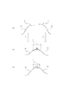
図1を用いて第1の本発明の形状計測方法を工程ごとに詳細に説明する。簡単のため、2つの断面データを接続する場合を説明する。また、第1のパラメータは座標変換にかかわるので、座標変換パラメータと記述する。また、第2のパラメータは近似誤差形状にかかわるので、形状パラメータと記述する。
(First embodiment)
The shape measuring method of the first aspect of the present invention will be described in detail for each step with reference to FIG. For simplicity, a case where two cross-section data are connected will be described. Since the first parameter is related to coordinate conversion, it is described as a coordinate conversion parameter. Since the second parameter is related to the approximate error shape, it is described as a shape parameter.
a)被測定物の複数の部分領域においてそれぞれ部分測定データを採取する工程
工程aについて、図1(a)で説明する。
図1において、A1,A2は2つの異なる測定領域での部分測定データを表している。座標測定装置の場合には、3次元的な位置データである。測定の際にそれぞれの部分測定データは必ずしもオーバーラップしている必要は無い。干渉計測装置の場合には参照波面との差による干渉縞が部分測定データとなる。
a) Step of collecting partial measurement data in each of a plurality of partial regions of the object to be measured Step a will be described with reference to FIG.
In FIG. 1, A 1 and A 2 represent partial measurement data in two different measurement regions. In the case of a coordinate measuring device, it is three-dimensional position data. In the measurement, the partial measurement data does not necessarily have to overlap. In the case of an interference measurement device, interference fringes due to a difference from the reference wavefront become partial measurement data.
b)座標変換パラメータを設定する工程
工程bについて、図1(b)で説明する。工程aで測定した部分測定データ同士はそのままではオーバーラップせず、被測定物の位置と姿勢とにずれを含むデータである考えてよい(測定装置の誤差を考えないことにする)。このずれは被測定物を座標測定装置にセットするときに発生する誤差であり、セッティング誤差と呼ぶ。このセッティング誤差を補正し、部分測定データ同士を適切に接続させるために座標変換T1,T2を用いる。座標変換は一般に6自由度(XYZの平行移動と、XYZ軸回りの回転移動)が考えられる。
この座標変換を行った結果を同図に示すようにBnとし、部分測定データAnを座標変換した形状をBn=Tn(An)と表現する。
b) Step for Setting Coordinate Conversion Parameter Step b will be described with reference to FIG. The partial measurement data measured in step a may not be overlapped as they are, but may be considered as data including a deviation in the position and orientation of the object to be measured (the error of the measurement apparatus is not considered). This deviation is an error that occurs when the object to be measured is set in the coordinate measuring apparatus, and is called a setting error. Coordinate transformations T 1 and T 2 are used to correct this setting error and connect the partial measurement data appropriately. The coordinate transformation is generally considered to have six degrees of freedom (XYZ parallel movement and rotational movement about the XYZ axes).
The coordinate transformation was performed results and B n as shown in the figure, representing the partial measurement data A n coordinate transformation shape with B n = T n (A n ).
次に変換の具体例を説明し、この変換の性質を述べる。座標変換パラメータは6自由度ある。これをX,Y,Z方向の移動と、X,Y,Z軸回りの回転とし、そのパラメータの名称をα1〜α6とすると4×4の同時座標変換行列は次のように記述できる。 Next, a specific example of conversion will be described, and the nature of this conversion will be described. The coordinate conversion parameter has 6 degrees of freedom. If this is the movement in the X, Y, and Z directions and the rotation about the X, Y, and Z axes, and the parameter names are α 1 to α 6 , the 4 × 4 simultaneous coordinate transformation matrix can be described as follows: .
ここで、パラメータの初期値は、被測定物の測定位置とする。例えばX方向に100mmずらして測定する場合は、α1を100mmとする。後述する工程fで収束計算するので、この初期値を厳密な値に設定する必要は無い。 Here, the initial value of the parameter is the measurement position of the object to be measured. For example, when measuring by shifting 100 mm in the X direction, α 1 is set to 100 mm. Since convergence calculation is performed in step f described later, it is not necessary to set this initial value to a strict value.

ここで、TransはX,Y,Z方向の平行移動を表し、RotxはX軸回りの回転、RotyはY軸回りの回転、RotzはZ軸回りの回転を表す。 Here, Trans represents translation in the X, Y, and Z directions, Rotx represents rotation about the X axis, Roty represents rotation about the Y axis, and Rotz represents rotation about the Z axis.
そして、前述した部分測定データを座標変換する工程とは、位置ベクトルをこの行列に掛けることを意味している。 The step of converting the partial measurement data described above means to multiply the matrix by the position vector.
部分測定データは測定点の集合であるが、右下の数字でそれぞれの測定点を区別する。次式は第m番目の測定点An mをBn mに座標変換する式である。
Bn m=TnAn m (式2)
これまでの式から明らかなように座標変換はパラメータα1〜α6に対しし、Sin関数やCos関数を含む、非線形な変換である。この座標変換パラメータα1〜α6は、このままでは最適化することは困難であることは既に述べた。干渉計測による従来技術と比べ座標測定装置による測定はミスマッチが大きく、前述したように、座標測定装置では座標変換の量、すなわち座標変換パラメータの値が大きくなるからである。
The partial measurement data is a set of measurement points, and each measurement point is distinguished by a number on the lower right. The following expression is an expression for coordinate-transforming the mth measurement point A n m to B n m .
B n m = T n A n m (Formula 2)
As is apparent from the equations so far, the coordinate transformation is a nonlinear transformation including the Sin function and the Cos function for the parameters α 1 to α 6 . As described above, it is difficult to optimize the coordinate transformation parameters α 1 to α 6 as they are. This is because the measurement by the coordinate measuring apparatus has a larger mismatch than the conventional technique by the interference measurement, and as described above, the coordinate measuring apparatus has a large amount of coordinate conversion, that is, the value of the coordinate conversion parameter.
したがって、座標測定装置による部分測定データの結合させる際には、座標変換パラメータを単なる線形結合として表現(特許文献1、特許文献2の方法)できない。特許文献1、特許文献2は、線形の仮定が成り立つ場合、すなわち座標変換のパラメータα1〜α6の数字が非常に小さい場合だけに使える技術と言える。
Therefore, when the partial measurement data is combined by the coordinate measuring apparatus, the coordinate conversion parameter cannot be expressed as a simple linear combination (the methods of
本発明のように、上式のような座標変換、すなわち非線形な変換が必要である。以下の工程cの項目において、座標変換のパラメータα1〜α6を最適化するために用いる形状パラメータについて述べる。また、図中の2はオーバーラップ領域を表している。この領域がどのように決定されるかは工程fの項目で説明する。また、この図では説明のために、B1とB2はわざと上下にずらして描いている。 As in the present invention, coordinate transformation as in the above equation, that is, nonlinear transformation is required. In the following step c, the shape parameters used for optimizing the coordinate conversion parameters α 1 to α 6 will be described. Moreover, 2 in the figure represents an overlap region. How this area is determined will be described in the item of step f. In this figure, B 1 and B 2 are intentionally shifted up and down for explanation.
c)すべての複数の部分測定データに共通する近似誤差形状を形状パラメータを用いて設定する工程
工程cについて、図1(c)で説明する。
形状パラメータβを定義し、近似誤差形状を決める工程である。近似誤差形状は測定領域全部にわたって決め、すべての複数の部分測定データに共通する近似誤差形状を表現する。
c) Step of Setting Approximate Error Shape Common to All Multiple Partial Measurement Data Using Shape Parameters Step c will be described with reference to FIG.
This is a step of defining an approximate error shape by defining a shape parameter β. The approximate error shape is determined over the entire measurement region, and an approximate error shape common to all the plurality of partial measurement data is expressed.
例えば簡便な方法として、多項式で近似誤差形状を表現する方法がある。この場合、形状パラメータβは多項式の係数となり、近似誤差形状を決めるとは多項式を算出することを意味している。この近似誤差形状を図のようにFとする。この工程で決めた近似誤差形状Fは暫定的なものであり、後に説明する最適化する際に前述の座標変換パラメータとともに、最適化される。 For example, as a simple method, there is a method of expressing an approximate error shape by a polynomial. In this case, the shape parameter β is a coefficient of a polynomial, and determining the approximate error shape means calculating a polynomial. Let this approximate error shape be F as shown. The approximate error shape F determined in this step is provisional, and is optimized together with the above-described coordinate conversion parameters when optimization described later is performed.
d)近似誤差形状を含む参照形状を設定する工程。
工程dについて、図1(d)で説明する。
工程cで計算した近似誤差形状Fと、被測定物の設計形状Dを加えて全ての部分測定データに共通する参照形状Gを得る。
G=D+F (式3)
しかし、被測定物の設計形状がわからない場合も現実にはある。そこで、被測定物の設計形状が不明の場合には近似誤差形状そのものを参照形状とする。上式でDがゼロの特別な場合である。つまり近似誤差形状を参照形状とする、または前記近似誤差形状と被測定物の設計形状とを加えて参照形状とすればよい。
d) A step of setting a reference shape including the approximate error shape.
Step d will be described with reference to FIG.
A reference shape G common to all partial measurement data is obtained by adding the approximate error shape F calculated in step c and the design shape D of the object to be measured.
G = D + F (Formula 3)
However, there are cases where the design shape of the object to be measured is unknown. Therefore, when the design shape of the object to be measured is unknown, the approximate error shape itself is used as the reference shape. This is a special case where D is zero. That is, the approximate error shape may be used as a reference shape, or the approximate error shape and the design shape of the object to be measured may be added to obtain a reference shape.
e)複数の部分測定データと、参照形状との差を差形状として計算し、その差形状の値から評価値を設定する工程
工程eについて、図1(e)で説明する。
工程bで得た、座標変換後の部分測定結果Bnと、工程dで得た参照形状Gとの差であるCnを計算する。Cnは差形状と呼ぶことにする。
Cn=Bn−G (式4)
これから評価値Qを計算する。最も簡便な評価値は2乗和である。すなわち、
e) A step of calculating a difference between a plurality of partial measurement data and a reference shape as a difference shape, and setting an evaluation value from the value of the difference shape Step e will be described with reference to FIG.
C n , which is the difference between the partial measurement result B n after coordinate conversion obtained in step b and the reference shape G obtained in step d, is calculated. C n is called a difference shape.
C n = B n -G (Formula 4)
The evaluation value Q is calculated from this. The simplest evaluation value is the sum of squares. That is,
ここで、添え字は前述したように
右上の添え字nは複数の測定データに対応する、測定番号を表す。
右下の添え字mはそれぞれの要素、一つの測定点の番号を表す。
上式の評価値Qには、前述した、第1のパラメータ、すなわち座標変換パラメータαがTの中に含まれている。
Here, as described above, the subscript n represents the measurement number corresponding to a plurality of measurement data.
The subscript m in the lower right represents the number of each element and one measurement point.
The evaluation value Q in the above equation includes the above-described first parameter, that is, the coordinate conversion parameter α in T.
また、形状パラメータβが近似誤差形状Fに含まれている。 In addition, the shape parameter β is included in the approximate error shape F.
そして、それらのパラメータ、αとβ、を変化させると、評価値Qの値が変化する。 When these parameters, α and β, are changed, the evaluation value Q changes.
f)評価値が小さくなるように、座標変換パラメータおよび形状パラメータを共に決定する工程
工程fについて、図1(f)で説明する。
工程fでは工程eで得た評価値Qが小さくなるようにパラメータα、βを調節し、決定する。評価値Qは(式4)で示した差形状Cn=Bn−Gから計算したので、この最適化により、差形状がゼロ、すなわち、座標変換した部分測定データBnがそれぞれ共通の参照形状Gにフィットすることを意味している。
f) Step of determining both coordinate transformation parameters and shape parameters so that the evaluation value becomes small Step f will be described with reference to FIG.
In step f, parameters α and β are adjusted and determined so that the evaluation value Q obtained in step e becomes small. Since the evaluation value Q is calculated from the difference shape C n = B n −G shown in (Equation 4), this optimization results in the difference shape being zero, that is, the coordinate-converted partial measurement data B n is a common reference. It means to fit the shape G.
最適化するパラメータの中の座標変換パラメータαは、被測定物のセッティング誤差を補正するためのものである。後でも述べるが、この方法によりセッティング誤差、すなわち測定データの場所のずれを精密に補正することができる。ただし、フィットする両者、測定データの形と、参照形状とがほぼ一致していることが必要である。 The coordinate conversion parameter α among the parameters to be optimized is for correcting the setting error of the object to be measured. As will be described later, this method can accurately correct a setting error, that is, a shift in the location of measurement data. However, it is necessary that the fitting data, the shape of the measurement data, and the reference shape are substantially the same.
最適化するパラメータの中の形状パラメータβは、そのために存在する。 The shape parameter β among the parameters to be optimized exists for that purpose.
この形状パラメータβが変化することで、近似誤差形状Fが変化し、そのことによって参照形状Gを測定データの形Bnに近づけることができる。 By changing the shape parameter β, the approximate error shape F is changed, whereby the reference shape G can be brought close to the shape Bn of the measurement data.
そしてそのように最適化された上でパラメータ決定された前記座標変換パラメータ及び形状パラメータを用いて部分測定データを接続すれば、被測定物の測定領域全体の形状を算出することができる。 Then, if the partial measurement data is connected using the coordinate conversion parameter and the shape parameter that have been optimized after such optimization, the shape of the entire measurement region of the object to be measured can be calculated.
この方法によれば次の効果があり、従来の課題を解決できる。 This method has the following effects and can solve the conventional problems.
本発明では近似誤差形状Fを用いることで測定領域全部を使用し、座標変換パラメータαを最適化する。この計算で、測定データがフィットできる位置は一つしかない。もし場所が少しでもずれれば、差形状(Cn=Bn−G)が急激に大きくなり、評価値も急激に悪化するからである。従来技術ではオーバーラップする狭い領域のデータだけで計算していたので、座標測定装置によるミスマッチの大きい部分測定データを接続させる際には位置が定まらなかったのである。 In the present invention, by using the approximate error shape F, the entire measurement region is used, and the coordinate conversion parameter α is optimized. In this calculation, there is only one position where the measurement data can be fitted. This is because if the location is shifted even a little, the difference shape (C n = B n -G) increases rapidly and the evaluation value also deteriorates rapidly. In the prior art, the calculation is performed only with data in a narrow overlapping region, and therefore the position cannot be determined when connecting the partial measurement data having a large mismatch by the coordinate measuring device.
このように、本発明によれば部分測定データの場所のずれを精密に決定できる。その結果、部分測定データの相対位置も精密に決定できる。 As described above, according to the present invention, it is possible to accurately determine the shift of the location of the partial measurement data. As a result, the relative position of the partial measurement data can also be determined accurately.
従って本発明によれば、従来技術の「オーバーラップ領域を高精度に決定できないので精度が悪い」、という課題を解決できる。 Therefore, according to the present invention, the problem of “accuracy is poor because the overlap region cannot be determined with high accuracy” can be solved.
また、本発明では、部分測定データが重なっているか否かの概念、すなわち、オーバーラップ領域の概念は使っていない。 In the present invention, the concept of whether or not the partial measurement data overlap, that is, the concept of the overlap region is not used.
従って、従来技術を座標測定装置に適用した際に生じる以下の3つの課題は存在しなくなる。
(1)「オーバーラップ領域のわずかな変化が大きく全体形状に影響するので精度が悪い」
(2)「オーバーラップ領域を精密探索する必要があるので時間がかかる」
(3)「オーバーラップ領域で異なる部位にフィットし、測定誤差が大きくなる危惧がある」
また、本明細書では評価値を小さくすることが最適である場合を暗黙に仮定した。
Therefore, the following three problems that occur when the prior art is applied to the coordinate measuring apparatus are not present.
(1) “Accuracy is poor because a slight change in the overlap area greatly affects the overall shape”
(2) “It takes time because it is necessary to search the overlap area precisely”
(3) “There is a risk that measurement errors will increase due to fitting to different parts in the overlap region.”
Further, in this specification, it is implicitly assumed that it is optimal to reduce the evaluation value.
評価値を大きくすることが最適である場合には評価値にマイナスの符号をつけるだけよい。従来技術ではオーバーラップ領域での測定データ間の差、すなわちミスマッチを最小にする最適化を行っていた。これまで説明してきたように本発明ではオーバーラップの概念を使っていないし、ミスマッチも考慮してこなかった。本発明では、工程fで説明したように、複数ある部分測定データBnを一つの共通の参照形状Gにフィットする。 When it is optimal to increase the evaluation value, it is only necessary to add a minus sign to the evaluation value. In the prior art, optimization was performed to minimize the difference between measurement data in the overlap region, that is, mismatch. As described above, the present invention does not use the concept of overlap and has not considered mismatches. In the present invention, as described in the step f, a plurality of partial measurement data Bn is fitted to one common reference shape G.
その結果、各部分測定データはGを介して一致する。すなわち、結果的にミスマッチも小さくなるのでミスマッチに関する課題も本発明は持っていない。 As a result, each partial measurement data matches through G. That is, as a result, the mismatch is also reduced, so the present invention does not have a problem related to the mismatch.
(第二の実施形態)
また、本出願に係る第2の発明について、図1を用いてさらに詳細に説明する。
(Second embodiment)
The second invention according to the present application will be described in more detail with reference to FIG.
最適化された座標変換パラメータ及び形状パラメータを用いて複数の部分測定データを接続する際は、例えば以下のg1)、g2)、g3)の項目で説明される方法のいずれか一つの方法で接続することができる。 When connecting a plurality of partial measurement data using the optimized coordinate transformation parameters and shape parameters, for example, the connection is performed by any one of the methods described in the following items g1), g2), and g3). can do.
g1)複数の座標変換した部分測定データを重ね合わせ、全体の形状に変換する工程
工程g1について、図1(g1)で説明する。
工程fまでで、部分測定データの位置あわせは完了している。その結果、前述したようにオーバーラップ領域での測定データの差、すなわちミスマッチは小さいはずである。
図に示すように座標変換した部分測定データBを重ね合わせ、全体の形状Jを求める。
g1) A step of superimposing a plurality of coordinate-converted partial measurement data and converting it into an overall shape Step g1 will be described with reference to FIG. 1 (g1).
Up to step f, the alignment of the partial measurement data has been completed. As a result, as described above, the difference in measurement data in the overlap region, that is, the mismatch should be small.
As shown in the figure, the coordinate data of the partial measurement data B are superposed to obtain the overall shape J.
g2)複数の差形状を重ね合わせ、全体の差形状に変換し、これに参照形状を加えて全体の形状に変換する工程
工程g2について、図1(g2)で説明する。
工程fまでで、部分測定データの位置あわせは完了し、ミスマッチも小さいはずである。
差形状を重ね合わせ、全体の差形状Cを求め、これに参照形状Gを加え、全体の形状Jを求める。すなわち、
J=C+G
=C+D+F (式6)
g2) A process of superimposing a plurality of difference shapes, converting them to an overall difference shape, and adding a reference shape to this to convert to an overall shape Step g2 will be described with reference to FIG.
Up to step f, the alignment of the partial measurement data should be completed and the mismatch should be small.
The difference shapes are overlapped to obtain an overall difference shape C, and a reference shape G is added thereto to obtain an overall shape J. That is,
J = C + G
= C + D + F (Formula 6)
g3)複数の差形状を重ね合わせ、全体の差形状に変換し、これに近似誤差形状を加えて全体の誤差形状に変換する工程
工程g3について、図1(g3)で説明する。
工程fまでで、部分測定データの位置あわせは完了し、ミスマッチも小さいはずである。差形状を重ね合わせ、全体の差形状Cを求め、これに近似誤差形状Fを加え、全体の誤差形状Eを求める。すなわち、
E=C+F (式7)
工程g2とg3の式を見比べれば明らかだが、この形状は全体形状Jから設計形状Dを差し引いたものである。通常、光学素子の評価にとって重要なのは、設計形状からの偏差、すなわち誤差形状Eである。本発明によれば、全体形状の重ね合わせを簡便な方法で実現できる。
g3) A step of superimposing a plurality of difference shapes, converting them to an overall difference shape, and adding an approximate error shape to this to convert to an overall error shape Step g3 will be described with reference to FIG. 1 (g3).
Up to step f, the alignment of the partial measurement data should be completed and the mismatch should be small. The difference shapes are overlapped to obtain an overall difference shape C, and an approximate error shape F is added thereto to obtain an overall error shape E. That is,
E = C + F (Formula 7)
As apparent from a comparison of the expressions of the steps g2 and g3, this shape is obtained by subtracting the design shape D from the overall shape J. In general, what is important for evaluation of an optical element is a deviation from a design shape, that is, an error shape E. According to the present invention, it is possible to realize superposition of the entire shape by a simple method.
(第三の実施形態)
また、本出願に係る第3の発明は、系統誤差にかかわる。
(Third embodiment)
The third invention according to the present application relates to a systematic error.
次に、図5を用いてさらに詳細に説明する。 Next, further details will be described with reference to FIG.
系統誤差とは測定装置が固有に持っている誤差のことである。測定誤差を測定ごとにばらつく成分と、ばらつかない成分とに分類したとき、後者のことである。この系統誤差は何らかの方法で測定して補正することが必要である。本発明によれば以下に説明するように、系統誤差も最適化するパラメータに含めてしまうことにより、補正することが可能である。 The systematic error is an error inherent in the measuring device. This is the latter when the measurement error is classified into components that vary from measurement to measurement and components that do not vary. This systematic error needs to be measured and corrected by some method. According to the present invention, it is possible to correct by including the systematic error in the parameter to be optimized as described below.
図5において、工程aは測定データを得る工程である。ここで、A1,A2は系統誤差を含んだ測定データである。 In FIG. 5, step a is a step of obtaining measurement data. Here, A 1 and A 2 are measurement data including systematic errors.
h)系統誤差パラメータを設定する工程
工程hについて、図5(h)で説明する。
系統誤差パラメータをγとし、これを用いて系統誤差Hを計算する。例えば簡便な系統誤差の表現方法として多項式で表現する方法がある。この場合、系統誤差パラメータγは多項式の係数となり、系統誤差Hを決めることは、その系統誤差を表現した多項式を決定することを意味している。こうして図5の(h)にHで示された系統誤差を設定する。
h) Step of Setting System Error Parameter Step h will be described with reference to FIG.
The systematic error parameter is set to γ, and the systematic error H is calculated using this. For example, as a simple systematic error expression method, there is a method expressed by a polynomial. In this case, the systematic error parameter γ is a polynomial coefficient, and determining the systematic error H means determining a polynomial expressing the systematic error. Thus, the systematic error indicated by H is set in (h) of FIG.
この時、系統誤差パラメータγは後述するように、工程fで前述の座標変換パラメータα、形状パラメータβなどと共に決定される。 At this time, the systematic error parameter γ is determined together with the above-described coordinate transformation parameter α, shape parameter β, etc. in step f, as will be described later.
j)座標変換パラメータを設定する工程b)の前に系統誤差を部分測定データから差し引く工程
工程jについて、図5(j)で説明する。
それぞれの部分測定データAnから系統誤差Hを差し引き、新たな測定データを得る。すなわち、次式を計算する。
Kn=An−H (式8)
それぞれの部分測定データAnは同じ測定装置で測定したデータであるので、系統誤差は全部の測定データに対して共通である。
j) The step of subtracting the systematic error from the partial measurement data before the step b) of setting the coordinate conversion parameters Step j will be described with reference to FIG.
Subtracting the systematic error H from the respective partial measurement data A n, obtaining a new measurement data. That is, the following equation is calculated.
K n = A n −H (Formula 8)
Since each partial measurement data An is data measured by the same measurement apparatus, the systematic error is common to all measurement data.
この後の手段と作用は、本発明における第1の発明と同じなので説明を省略するが、パラメータを最適化する工程fに、系統誤差パラメータγを加えた点だけが異なる。本発明では工程fで最適化するパラメータは、次の3種類になる。それは、座標変換パラメータα、形状パラメータβ、系統誤差パラメータγ、である。 Subsequent means and actions are the same as those of the first invention of the present invention, and thus description thereof will be omitted. However, only the system error parameter γ is added to the parameter optimizing step f. In the present invention, there are the following three types of parameters to be optimized in step f. They are a coordinate conversion parameter α, a shape parameter β, and a systematic error parameter γ.
以上説明してきた方法によれば、系統誤差が存在しても、これを補正することができ、測定精度をさらに向上させることが可能である。 According to the method described above, even if a systematic error exists, it can be corrected and the measurement accuracy can be further improved.
また、本発明ではパラメータを簡便な多項式の係数として表現することにより、計算負荷を減らし、高速なデータ処理を可能にすることができる。 Further, in the present invention, by expressing the parameters as simple polynomial coefficients, the calculation load can be reduced and high-speed data processing can be performed.
図1あるいは図5で説明したように、工程fで最適化するパラメータ(α、β、γ)は次の3種類であった。
(1)座標変換パラメータ(α)
(2)形状パラメータ(β)
(3)系統誤差パラメータ(γ)
このうち、(1)は式1で示したように三角関数を含む非線形なパラメータである。本発明では残りのパラメータを次式に示す多項式で表現する。具体的には横座標をx、yとし、近似誤差形状Fを、パラメータβを使って次のように表現する。
As described with reference to FIG. 1 or FIG. 5, the parameters (α, β, γ) to be optimized in step f are the following three types.
(1) Coordinate conversion parameter (α)
(2) Shape parameter (β)
(3) System error parameter (γ)
Among these, (1) is a non-linear parameter including a trigonometric function as shown in
![]()
![]()
ここで、βiはi番目の形状パラメータ、niはxの乗数,miはyの乗数である。後述する工程fで収束計算するので、このパラメータの初期値は全部ゼロとしてもよい。また、この近似誤差形状Fは被測定物に固定した形状である。従って上式のXY座標も被測定物に固定した座標である。 Here, βi is the i-th shape parameter, ni is a multiplier of x, and mi is a multiplier of y. Since the convergence calculation is performed in step f to be described later, the initial values of this parameter may be all zero. The approximate error shape F is a shape fixed to the object to be measured. Therefore, the XY coordinates in the above equation are also fixed to the object to be measured.
また、系統誤差パラメータγ、および系統誤差Hも同様に定義できる。 Further, the systematic error parameter γ and the systematic error H can be defined similarly.
![]()
![]()
ここで、γiは系統誤差パラメータ、niはxの乗数,miはyの乗数である。また、この系統誤差は測定装置に固定した形状である。従って上式のXY座標も測定装置に固定した座標である。後述する工程fで収束計算するので、このパラメータの初期値は全部ゼロとしてもよい。一般に、パラメータを最適化するとき、各パラメータが独立、つまり区別できないと収束しない。本発明において、この条件が可能であることを説明する。 Here, γi is a systematic error parameter, ni is a multiplier of x, and mi is a multiplier of y. Further, this systematic error has a shape fixed to the measuring device. Therefore, the XY coordinates in the above equation are also fixed to the measuring device. Since the convergence calculation is performed in step f to be described later, the initial values of this parameter may be all zero. In general, when parameters are optimized, the parameters do not converge unless the parameters are independent. In the present invention, it will be explained that this condition is possible.
まず、(1)の座標変換パラメータ、αは式1で示したように三角関数を含む非線形なパラメータなので、他の線形なパラメータとは区別できる。
First, since the coordinate conversion parameter α in (1) is a non-linear parameter including a trigonometric function as shown in
残りの2つのパラメータは両方多項式だが、(1)は被測定物に固定した形状であり、(3)は測定装置に固定した形状である。両者の位置は測定ごとに変わるので互いに区別できる。 The remaining two parameters are both polynomials, but (1) is the shape fixed to the object to be measured, and (3) is the shape fixed to the measuring device. Since the positions of the two change with each measurement, they can be distinguished from each other.
図5で説明すると、(2)の近似誤差形状は図5(c)のFであり、被測定物に固定した形状である。一方(3)の系統誤差は図5(h)のHである。複数の測定データA1,A2は被測定物と測定装置の位置をずらして測定する。従って、被測定物に固定した形状であるFと、装置に固定した形状であるHは区別できる。 Referring to FIG. 5, the approximate error shape in (2) is F in FIG. 5 (c), which is a shape fixed to the object to be measured. On the other hand, the systematic error in (3) is H in FIG. The plurality of measurement data A 1 and A 2 are measured by shifting the positions of the object to be measured and the measuring device. Therefore, F which is a shape fixed to the object to be measured and H which is a shape fixed to the apparatus can be distinguished.
また、多項式の項の中で、場所をずらしても区別できない項は除外してパラメータを選択すれば良い。例えば定数項である。 Further, the parameters may be selected by excluding the terms that cannot be distinguished even if the location is shifted from the polynomial terms. For example, a constant term.
本実施形態によれば、単純な多項式を使っているので計算負荷が少なく、高速なデータ処理が可能である。 According to this embodiment, since a simple polynomial is used, the calculation load is small and high-speed data processing is possible.
また、パラメータを最適化するとき、各パラメータが独立、つまり区別できないと収束しない。前述した座標変換パラメータαの中には、被測定物の形状によって非独立変数になるものが含まれているので注意が必要である。例えば以下のような場合がある。 Also, when optimizing parameters, the parameters will not converge unless they are independent, that is, cannot be distinguished. It should be noted that the coordinate transformation parameter α described above includes a variable that becomes a non-independent variable depending on the shape of the object to be measured. For example, there are the following cases.
被測定物が平面の場合、独立なパラメータは3つである。例えばZ=0の平面では垂直方向のZおよびX,Y軸回りの回転θx、θyである。残りの水平方向のX,YおよびZ軸回りの回転θzは区別できないので、座標変換パラメータには含めない。 When the object to be measured is a plane, there are three independent parameters. For example, in the plane of Z = 0, the rotation is the vertical Z and the rotations θx and θy about the X and Y axes. The remaining rotations θz around the X, Y and Z axes in the horizontal direction cannot be distinguished and are not included in the coordinate conversion parameters.
同様に被測定物が球面の場合、独立なパラメータは3つである。例えば球面の中心座標X,Y,Zである。また、被測定物が軸対称非球面レンズの場合は軸まわりの回転を除く5つのパラメータとする。平面や球面、および軸対称非球面でも安定して座標変換パラメータを計算することができる。 Similarly, when the object to be measured is a spherical surface, there are three independent parameters. For example, the center coordinates X, Y, Z of the spherical surface. When the object to be measured is an axisymmetric aspheric lens, five parameters excluding rotation around the axis are used. The coordinate transformation parameter can be calculated stably even on a plane, a spherical surface, and an axisymmetric aspherical surface.
ところで、評価値Qを差形状の2乗和とする場合は、すでに一例として式5でも示した。 By the way, in the case where the evaluation value Q is the sum of squares of the difference shape, it has already been shown in Expression 5 as an example.
再記すると、 If you rewrite,
![]()
![]()
評価値を差形状の最大、最小とする場合は、次の式を評価値Qとする。 When the evaluation value is the maximum or minimum of the difference shape, the following expression is used as the evaluation value Q.
![]()
![]()
このような評価値Qを用いると、評価値を単純な数式で計算できるので、計算負荷が少なく、高速なデータ処理が可能である。 When such an evaluation value Q is used, the evaluation value can be calculated with a simple mathematical formula, so that the calculation load is small and high-speed data processing is possible.
(第四の実施形態)
被測定物が持っている形状誤差を、近似誤差形状Fで代表している。このとき、近似誤差形状Fで表現しきれない残差が大きいと、実際の測定データとの差形状Cが小さくならない。結局工程Fの収束が悪くなるので計算誤差が大きくなってしまう。
(Fourth embodiment)
The shape error of the object to be measured is represented by the approximate error shape F. At this time, if the residual that cannot be expressed by the approximate error shape F is large, the difference shape C from the actual measurement data does not become small. Eventually, the convergence of the process F becomes worse, and the calculation error becomes larger.
本発明はこの課題を解決するものである。 The present invention solves this problem.
図6を用い、第1の発明の項で説明した内容と異なる点について、主に説明する。 Differences from the content described in the first invention will be mainly described with reference to FIG.
工程aと工程bの間に行なわれる工程mについて、図6(m)で説明する。 The process m performed between the process a and the process b will be described with reference to FIG.
工程aで得られる測定データには空間周波数の高い成分が含まれているとする。このような成分は、被測定物がもともと持っている場合もあるし、測定時にノイズとして混入する場合もある。このような高周波成分は、工程cで定義した近似誤差形状Fでは表現しにくい。なぜならば、周波数が高いということは、必要とするパラメータの数も多くなるからである。パラメータの数が多いと、最適化するときの計算時間も急増してしまう。そこで、工程mを設け、高周波成分を分離する。 It is assumed that the measurement data obtained in step a includes a component having a high spatial frequency. Such a component may be originally possessed by the object to be measured, or may be mixed as noise during measurement. Such a high frequency component is difficult to express with the approximate error shape F defined in step c. This is because a high frequency requires a large number of parameters. When the number of parameters is large, the calculation time for optimization also increases rapidly. Therefore, a process m is provided to separate high frequency components.
工程mでは、それぞれの形状データAnにハイパスフィルタをかけて高周波成分Mnを抽出する。また、形状データAnから高周波成分Mnを差し引き、新たにこれをAnとおく。こうして計算したAnは、ある特定の高い周波数成分が除去されているため、前述した問題、近似誤差形状で表現できないという問題は解決できる。 In step m, and it extracts the high frequency components M n over a high pass filter to each of the shape data A n. Further, subtracting high frequency components M n from the shape data A n, newly put to as A n. A n thus calculated is for certain high frequency components have been removed, the aforementioned problems, a problem that can not be expressed by the approximation error shape can be solved.
パラメータを最適化する工程f)までは、第1の発明と同じである。 The process up to step f) for optimizing the parameters is the same as in the first invention.
工程f)に続いて行なわれる工程nについて、図6(n)で説明する。 Step n performed subsequent to step f) will be described with reference to FIG.
最適化が終わったあと、工程mで抽出した高周波成分を再びもとに戻し、あらためてBnとする。このあとの手順は第1の発明と同じである。こうして、測定データに高い空間周波数が含まれていても、高精度に計算することが可能となる。 After optimization is completed, the high-frequency component extracted in step m is returned to its original state, and is again set as Bn . The subsequent procedure is the same as in the first invention. Thus, even if the measurement data includes a high spatial frequency, it can be calculated with high accuracy.
また、等式制約条件にかかわる制約パラメータをさらに導入してもよい。 In addition, constraint parameters related to the equality constraint condition may be further introduced.
これまで測定データ間の差、すなわちミスマッチをゼロに近づけることが可能であることを説明してきた。 So far, it has been explained that the difference between measurement data, that is, the mismatch can be made close to zero.
本発明ではさらにこの条件、ミスマッチをゼロにするという条件を明示的に付加することによって、より精密にミスマッチをゼロにできる。 In the present invention, the mismatch can be zeroed more precisely by explicitly adding this condition, that is, the condition of zero mismatch.
前述したように、ラグランジュの未定乗数法を用いれば、等式制約条件を有する最適化問題を解けることが知られている。本発明では、この等式制約条件に、ミスマッチをゼロとする等式を採用する。具体的手順を図7を用いて示す。 As described above, it is known that the Lagrange's undetermined multiplier method can solve an optimization problem having equality constraints. In the present invention, an equation with zero mismatch is adopted as the equation constraint. A specific procedure is shown using FIG.
第1の発明の項目と異なる点について、図7の(e,p)で説明する。座標変換した測定でデータBnどおしのオーバーラップ領域2、において両者の差Pを計算する。
Bn1とBn2の差をPn1,n2などと表す。例えばB2とB1の差をP21とする。
Differences from the items of the first invention will be described with reference to (e, p) in FIG. The difference P between the two is calculated in the
The difference between B n1 and B n2 is expressed as P n1, n2 and the like. For example, let P 21 be the difference between B 2 and B 1 .
前述したように、この測定データ間の差は、ミスマッチと呼ばれている。図では説明のためミスマッチを誇張して描いている。
Pn1,n2=0はミスマッチがゼロ、すなわちBn1とBn2が重なっている領域において一致していることを意味している。この条件を最適化工程f)において等式制約条件として採用する。
As described above, this difference between measurement data is called a mismatch. In the figure, the mismatch is exaggerated for explanation.
P n1, n2 = 0 means that the mismatch is zero, that is, in a region where B n1 and B n2 overlap. This condition is adopted as an equality constraint in the optimization step f).
制約パラメータλmnを設け、このパラメータとミスマッチを掛けたものを評価値Qに加える。例えば、式5にあげた評価値の式で説明すると次のようになる。 A constraint parameter λ mn is provided, and this parameter multiplied by a mismatch is added to the evaluation value Q. For example, the evaluation value expression given in Expression 5 is described as follows.
![]()
![]()
次に工程fにおいて、パラメータを調節し、上記評価値Qを最適化するが、この時の調節するパラメータに制約パラメータλmnを含める。 Next, in step f, the parameter is adjusted to optimize the evaluation value Q, and the constraint parameter λ mn is included in the parameter to be adjusted at this time.
以上説明したように、ラグランジェの未定乗数法を適応することによりPn1,n2がゼロ、すなわち、ミスマッチをより精密にゼロにすることができる。 As described above, by applying the Lagrange's undetermined multiplier method, P n1 and n2 can be zero, that is, the mismatch can be zero more precisely.
本発明における第1の実施例を図1、図8、図9に基づいて説明する。 A first embodiment of the present invention will be described with reference to FIGS. 1, 8, and 9. FIG.
図8は座標測定装置の例である。この図は装置本体5に大型の被測定物1を搭載したところを示している。この装置は接触式のプローブ6を、XYZの3軸方向に移動可能なXYZスライド7に取り付け、被測定物表面1にプローブ6を押し当て、被測定物表面を走査する。この時のプローブの動きをメトロロジフレーム8に固定した参照ミラーを計測の基準に使って測定する装置である。図中9はZ方向の参照ミラーである。
FIG. 8 shows an example of a coordinate measuring apparatus. This figure shows a state where a
被測定物が大きい場合、全面を一度の測定でカバーすることができないため、部分測定を繰り返して複数の部分測定データを得た後に、それらをつなぎ合わせる必要がある。 When the object to be measured is large, the entire surface cannot be covered with a single measurement. Therefore, after partial measurement is repeated to obtain a plurality of partial measurement data, it is necessary to connect them.
図9はレンズのような円形の被測定物1を3回に分割して測定する例である。被測定物の姿勢を120度づつ回転させて、さきほどの座標測定装置にセットし、部分測定を行う。1回の部分測定領域をLnとする。右肩の数字は測定の番号を表している。部分測定領域Lnは図のように、3回の測定で被測定物の全面をカバーする配置である。
FIG. 9 shows an example in which a
この3つの部分測定から、3つの部分測定データA1,A2,A3が得られる。 From the three partial measurements, three partial measurement data A 1 , A 2 , A 3 are obtained.
ここで、座標変換パラメータの初期値は、被測定物の測定位置とする。例えばX方向に100mmずらして測定する場合は、α1を100mmとする。この初期値を厳密な値に設定する必要は無い。 Here, the initial value of the coordinate conversion parameter is the measurement position of the object to be measured. For example, when measuring by shifting 100 mm in the X direction, α 1 is set to 100 mm. It is not necessary to set this initial value to a strict value.
このデータ処理の内容、および効果については上に詳細に説明したので、省略する。 Since the contents and effects of this data processing have been described in detail above, they will be omitted.
測定領域が小さい測定装置でも本発明によれば、部分測定をつなぎ合わせて大きな被測定物全面の測定データが得られる。 Even with a measuring device having a small measuring area, according to the present invention, it is possible to connect partial measurements and obtain measurement data on the entire surface of a large object to be measured.
また、本実施形態では部分測定領域の数が3つの場合を説明したが、2つ以上であれば他の数でも同じである。 In the present embodiment, the case where the number of partial measurement regions is three has been described. However, if the number is two or more, other numbers are the same.
図10に本発明における第2の実施例を示す。前節で説明した方法は被測定物の回転姿勢を変更して、複数回測定したデータを用いたが、この実施例は被測定物を横ずらしして測定装置にセットした場合である。 FIG. 10 shows a second embodiment of the present invention. The method described in the previous section uses data measured a plurality of times by changing the rotation posture of the object to be measured, but this embodiment is a case where the object to be measured is laterally shifted and set in the measuring apparatus.
作用および効果は、さきほどと同様なので説明を省略する。 Since the operation and effect are the same as before, the description thereof is omitted.
本発明は、このように部分測定の数については2つ以上であれば適応可能である。また、オーバーラップのさせ方も、前節のように回転させてオーバーラップさせても良いし、横ずらししてオーバーラップさせても適応可能である。 The present invention can be applied to the number of partial measurements as long as it is two or more. In addition, the overlapping method may be applied by rotating and overlapping as in the previous section, or by laterally shifting and overlapping.
さらに本発明はオーバーラップ領域が無くても適応可能である。この場合は測定結果の無い部分がまだら模様のように残ってしまうが、全体が滑らかであるという仮定が成り立つとすれば、全体形状を概略知ることができる。 Furthermore, the present invention can be applied without an overlap region. In this case, a portion without a measurement result remains like a mottled pattern, but if it is assumed that the whole is smooth, the overall shape can be roughly known.
また、反対にほぼ全部がオーバーラップ領域であっても良い。この場合は測定結果を合成したところで、測定領域が広がったことにはならない。しかしオーバーラップ領域では複数の測定結果を平均することになるので、測定精度を向上することができる。 On the contrary, almost the entire region may be an overlap region. In this case, the measurement area is not expanded when the measurement results are combined. However, since a plurality of measurement results are averaged in the overlap region, the measurement accuracy can be improved.
以上説明してきたように、本発明ではオーバーラップ領域という概念を使わなくても部分測定データを合成することができる。 As described above, in the present invention, partial measurement data can be synthesized without using the concept of an overlap region.
図8、図11を用い、本発明における第3の実施例を説明する。スティッチ技術は測定領域に対して大きな被測定物を測定するために開発された技術であるが、反対に小さな被測定物を測定し、測定装置の系統誤差を測定するのにも、本発明を使用できる。 A third embodiment of the present invention will be described with reference to FIGS. The stitch technique is a technique developed to measure a large object to be measured with respect to the measurement area. On the contrary, the present invention is also used to measure a small object to be measured and to measure a system error of the measuring apparatus. Can be used.
図8に示すような座標測定装置は一般的に精度の基準を持っている。例えばこの装置の場合は参照ミラー9であり、このミラーの形状誤差が、この装置における系統誤差の主要な原因となっている。 A coordinate measuring apparatus as shown in FIG. 8 generally has a standard of accuracy. For example, in the case of this apparatus, it is the reference mirror 9, and the shape error of this mirror is the main cause of the systematic error in this apparatus.
前述した本発明にかかる第3の実施形態によれば、被測定物の形と、系統誤差の形を両方、測定することが可能である。しかも両者のサイズの比率については制約がなかった。この実施例は被測定物のほうが小さい場合について、実施した例である。 According to the third embodiment of the present invention described above, it is possible to measure both the shape of the object to be measured and the shape of the systematic error. Moreover, there was no restriction on the size ratio between the two. This embodiment is an example in which the object to be measured is smaller.
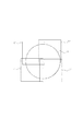
具体的には図11を使って説明する。 Specifically, this will be described with reference to FIG.
図11は図8に示した測定装置の測定領域を上からみた図である。9は参照ミラーであり、1は被測定物である。
まず図11(a)に示した位置に被測定物1をセットし、測定領域L1において部分測定データA1を測定する。
同様に図11(b)に示した位置に被測定物1をセットし、測定領域L2において部分測定データA2を測定する。
同様に図11(c)に示した位置に被測定物1をセットし、測定領域L3において部分測定データA3を測定する。
FIG. 11 is a top view of the measurement region of the measurement apparatus shown in FIG. Reference numeral 9 is a reference mirror, and 1 is an object to be measured.
First 11 sets the
Similarly sets the
Similarly it sets the
この部分測定データを得た後の処理は前に述べた方法と同様である。測定領域Lnの領域で定義される系統誤差と、部分測定でカバーする領域9を両方測定することが可能であった。その結果はそれぞれ、被測定物1の形と、参照ミラー9の形を表している。
The processing after obtaining the partial measurement data is the same as the method described above. And the system error defined by the area of the measurement region L n, it was possible to both measuring regions 9 which covers a partial measurement. The results represent the shape of the
本実施例では3回の測定から、系統誤差を測定する場合について説明した。しかし複数回であれば何回であっても同じことである。 In the present embodiment, the case where the systematic error is measured from three measurements has been described. However, the same is true no matter how many times it is multiple times.
また、本実施例では位置をずらす場合について、説明してきた。しかし回転方向の姿勢をずらす場合についても同じことである。 In the present embodiment, the case of shifting the position has been described. However, the same is true for shifting the orientation in the rotational direction.
さらに、位置をずらすことと回転方向の姿勢をずらすことを組合わせても同じことである。例えば、図11(a)、(b)、(c)の3箇所において、それぞれ、被測定物1を90度ずつ回転させて4方位測定すると、合計12箇所のデータが得られる。この12箇所の部分測定データを使い、系統誤差を計算しても同じことである。
Further, the combination of shifting the position and shifting the posture in the rotation direction is the same. For example, in four locations shown in FIGS. 11A, 11B, and 11C, when the
本実施例によれば、小さな被測定物を用い、測定装置のもつ系統誤差を測定することができる。この誤差を測定できれば、測定値から差し引くことによって測定精度を向上させることができる。 According to the present embodiment, it is possible to measure the systematic error of the measuring device using a small object to be measured. If this error can be measured, the measurement accuracy can be improved by subtracting from the measurement value.
1 被測定物(workpiece)
2 オーバーラップ領域(重ね合わせ領域)
3 目印形状5 座標測定装置(coordinate measurement m achine)
6 プローブ
7 XYZスライド
8 メトロロジフレーム(metrology frame)
9 Z方向の参照ミラー(Z − reference mirror)
A 部分測定データ
B 座標変換した部分測定データ
C 差形状 C=B−G
D 設計形状
E 全体の誤差形状(被測定物の測定結果)
F 近似誤差形状
G 参照形状 G=D+F
J 全体の形状(被測定物の測定結果)
H 系統誤差(systematic error)
K 系統誤差を補正した部分測定データ K=A−H
L 部分測定領域
1 work piece (workpiece)
2 Overlap area (overlapping area)
3 Marking shape 5 Coordinate measuring machine (coordinated measurement machine)
6 Probe 7 XYZ slide 8 Metrology frame
9 Reference mirror in the Z direction (Z-reference mirror)
A Partial measurement data B Coordinate converted partial measurement data C Difference shape C = BG
D Design shape E Overall error shape (measurement result)
F Approximate error shape G Reference shape G = D + F
J Overall shape (measurement result)
H systematic error
K Partial measurement data corrected for systematic error K = A-H
L Partial measurement area
Claims (5)
被測定物の複数の部分領域においてそれぞれ部分測定データを測定装置によって採取する工程と、
複数の前記部分測定データのそれぞれを座標変換する座標変換パラメータを用いて座標変換する工程と、
前記複数の部分測定データに共通する近似誤差形状が設定され、前記近似誤差形状を含む参照形状を、形状パラメータを用いて設定する工程と、
前記複数の部分測定データと、前記参照形状との差を差形状として計算し、該差形状に対応して設定される評価値が、あらかじめ定められた値に近づくように前記座標変換パラメータおよび形状パラメータを共に決定するパラメータ決定工程と、
前記評価値を用いて共に決定された前記座標変換パラメータ及び形状パラメータを用いて部分測定データを接続する工程と、
を有することを特徴とする形状計測方法。 In the shape measurement method for calculating the overall measurement data by combining multiple partial measurement data of the object to be measured,
A step of collecting partial measurement data by a measuring device in each of a plurality of partial regions of the object to be measured;
A step of performing coordinate transformation using coordinate transformation parameters for coordinate transformation of each of the plurality of partial measurement data;
An approximate error shape common to the plurality of partial measurement data is set, and a reference shape including the approximate error shape is set using a shape parameter;
The difference between the plurality of partial measurement data and the reference shape is calculated as a difference shape, and the coordinate conversion parameter and shape are set so that an evaluation value set corresponding to the difference shape approaches a predetermined value. A parameter determination step for determining parameters together;
Connecting partial measurement data using the coordinate transformation parameters and shape parameters determined together using the evaluation values;
A shape measuring method characterized by comprising:
座標変換した前記複数の部分測定データを重ね合わせて全体の形状に変換する、もしくは、
座標変換した複数の前記差形状を重ね合わせて全体の差形状に変換し、これに前記参照形状を加えて全体の形状に変換する、
のいずれか一つの方法であることを特徴とする請求項1記載の形状計測方法。 The step of connecting the partial measurement data includes:
The plurality of partial measurement data that have undergone coordinate conversion are superimposed and converted into an overall shape, or
A plurality of the difference shapes that have undergone coordinate conversion are superimposed and converted to an overall difference shape, and the reference shape is added to this to convert to an overall shape,
The shape measuring method according to claim 1, wherein the method is any one of the methods.
前記パラメータ決定工程の後に部分測定データに分離した前記成分を再び加え合わせる工程を、有する請求項1〜3のいずれか1項に記載の形状計測方法。 Before performing the step of coordinate transformation using the coordinate transformation parameter, the step of separating a component larger than a specific spatial frequency from the partial measurement data,
The shape measuring method according to claim 1, further comprising a step of adding the components separated into the partial measurement data again after the parameter determining step.
Priority Applications (2)
| Application Number | Priority Date | Filing Date | Title |
|---|---|---|---|
| JP2008149366A JP5424581B2 (en) | 2008-06-06 | 2008-06-06 | Shape measurement method for combining partial measurements |
| US12/476,970 US8447561B2 (en) | 2008-06-06 | 2009-06-02 | Shape measurement method of synthetically combining partial measurements |
Applications Claiming Priority (1)
| Application Number | Priority Date | Filing Date | Title |
|---|---|---|---|
| JP2008149366A JP5424581B2 (en) | 2008-06-06 | 2008-06-06 | Shape measurement method for combining partial measurements |
Publications (3)
| Publication Number | Publication Date |
|---|---|
| JP2009294134A JP2009294134A (en) | 2009-12-17 |
| JP2009294134A5 JP2009294134A5 (en) | 2011-07-21 |
| JP5424581B2 true JP5424581B2 (en) | 2014-02-26 |
Family
ID=41401065
Family Applications (1)
| Application Number | Title | Priority Date | Filing Date |
|---|---|---|---|
| JP2008149366A Active JP5424581B2 (en) | 2008-06-06 | 2008-06-06 | Shape measurement method for combining partial measurements |
Country Status (2)
| Country | Link |
|---|---|
| US (1) | US8447561B2 (en) |
| JP (1) | JP5424581B2 (en) |
Cited By (1)
| Publication number | Priority date | Publication date | Assignee | Title |
|---|---|---|---|---|
| KR20220095471A (en) | 2020-12-30 | 2022-07-07 | 한국기초과학지원연구원 | Apparatus for measuring sub-aperture with surface extended radius of curvature range |
Families Citing this family (17)
| Publication number | Priority date | Publication date | Assignee | Title |
|---|---|---|---|---|
| JP5591063B2 (en) * | 2009-11-12 | 2014-09-17 | キヤノン株式会社 | Measuring method and measuring device |
| JP5417222B2 (en) * | 2010-03-05 | 2014-02-12 | 株式会社ミツトヨ | Tolerance detection method and apparatus for roundness measuring machine |
| JP5743495B2 (en) * | 2010-11-05 | 2015-07-01 | キヤノン株式会社 | Robot controller |
| JP5725883B2 (en) * | 2011-01-26 | 2015-05-27 | キヤノン株式会社 | Shape measurement method to synthesize partial measurement |
| JP5300929B2 (en) * | 2011-07-22 | 2013-09-25 | キヤノン株式会社 | Measuring method, measuring apparatus and program |
| JP5913900B2 (en) * | 2011-10-19 | 2016-04-27 | キヤノン株式会社 | Measuring method |
| JP5896789B2 (en) | 2012-03-07 | 2016-03-30 | キヤノン株式会社 | Robot control apparatus, robot apparatus, robot control method, program, and recording medium |
| JP6157953B2 (en) * | 2013-06-27 | 2017-07-05 | 株式会社ミツトヨ | 3D shape measurement system and control software |
| JP6238628B2 (en) | 2013-08-06 | 2017-11-29 | キヤノン株式会社 | Robot device, robot control method, robot control program, and part manufacturing method using robot device |
| JP6289001B2 (en) * | 2013-09-24 | 2018-03-07 | キヤノン株式会社 | Shape measuring method and shape measuring device |
| JP6452086B2 (en) * | 2013-10-31 | 2019-01-16 | キヤノン株式会社 | Shape calculating apparatus and method, measuring apparatus, article manufacturing method, and program |
| JP2016017744A (en) * | 2014-07-04 | 2016-02-01 | キヤノン株式会社 | Non-spherical surface measuring method, non-spherical surface measuring apparatus, program, machining apparatus for optical elements, and optical elements |
| JP6685741B2 (en) * | 2015-02-16 | 2020-04-22 | キヤノン株式会社 | Shape measuring method, shape measuring device, program, recording medium, and optical element manufacturing method |
| JP6700669B2 (en) | 2015-04-07 | 2020-05-27 | キヤノン株式会社 | Control method, robot device, program, recording medium, and article manufacturing method |
| CN109299515B (en) * | 2018-08-28 | 2021-08-13 | 西安交通大学 | Workpiece machining error analysis method based on installation error extraction and correction |
| US11045950B2 (en) | 2018-11-02 | 2021-06-29 | Canon Kabushiki Kaisha | Driving device and detecting device |
| US11748225B2 (en) | 2021-03-29 | 2023-09-05 | International Business Machines Corporation | Dynamic interface intervention to improve sensor performance |
Family Cites Families (18)
| Publication number | Priority date | Publication date | Assignee | Title |
|---|---|---|---|---|
| GB2202659B (en) * | 1987-02-23 | 1991-07-17 | Mitutoyo Corp | Coordinate measuring instrument and method of generating pattern data concerning shape of work to be measured |
| JP3041864B2 (en) | 1989-12-08 | 2000-05-15 | 株式会社ユアサコーポレーション | Polymer solid electrolyte lithium battery |
| JP2840108B2 (en) | 1990-03-22 | 1998-12-24 | キヤノン株式会社 | Paper feeder and recording apparatus using the paper feeder |
| US5343410A (en) * | 1991-03-19 | 1994-08-30 | Fuji Photo Optical Co., Ltd. | Method for divisional measurement of object surface, and method for joining object surface sub-areas measured by same |
| DE4342312A1 (en) * | 1993-12-11 | 1995-06-14 | Zeiss Carl Fa | Method for correcting vibration-related measurement errors in coordinate measuring machines |
| JP3182056B2 (en) | 1995-02-24 | 2001-07-03 | 株式会社リコー | Aspherical surface shape measuring method and apparatus / aspherical surface evaluating method |
| JP2996165B2 (en) * | 1996-01-05 | 1999-12-27 | キヤノン株式会社 | Shape measuring method and shape measuring device using the same |
| JP3272952B2 (en) | 1996-07-02 | 2002-04-08 | キヤノン株式会社 | 3D shape measuring device |
| GB9815830D0 (en) * | 1998-07-22 | 1998-09-16 | Renishaw Plc | Method of and apparatus for reducing vibrations on probes carried by coordinate measuring machines |
| JP3403668B2 (en) * | 1999-05-27 | 2003-05-06 | 理化学研究所 | Method of synthesizing partial measurement data |
| JP3634275B2 (en) * | 2001-03-05 | 2005-03-30 | 株式会社ミツトヨ | Position measuring device |
| JP4794753B2 (en) * | 2001-06-04 | 2011-10-19 | パナソニック株式会社 | Shape measurement method |
| US6956657B2 (en) * | 2001-12-18 | 2005-10-18 | Qed Technologies, Inc. | Method for self-calibrated sub-aperture stitching for surface figure measurement |
| GB2401937B (en) * | 2003-05-23 | 2006-07-19 | Taylor Hobson Ltd | Surface profiling apparatus |
| JP3923945B2 (en) * | 2004-01-13 | 2007-06-06 | 三鷹光器株式会社 | Non-contact surface shape measurement method |
| JP4390569B2 (en) * | 2004-01-19 | 2009-12-24 | 株式会社ミツトヨ | Signal processing apparatus and measuring machine |
| GB2425840A (en) * | 2005-04-13 | 2006-11-08 | Renishaw Plc | Error correction of workpiece measurements |
| JP4810251B2 (en) * | 2006-02-16 | 2011-11-09 | キヤノン株式会社 | Atomic force microscope |
-
2008
- 2008-06-06 JP JP2008149366A patent/JP5424581B2/en active Active
-
2009
- 2009-06-02 US US12/476,970 patent/US8447561B2/en not_active Expired - Fee Related
Cited By (1)
| Publication number | Priority date | Publication date | Assignee | Title |
|---|---|---|---|---|
| KR20220095471A (en) | 2020-12-30 | 2022-07-07 | 한국기초과학지원연구원 | Apparatus for measuring sub-aperture with surface extended radius of curvature range |
Also Published As
| Publication number | Publication date |
|---|---|
| US20090306931A1 (en) | 2009-12-10 |
| US8447561B2 (en) | 2013-05-21 |
| JP2009294134A (en) | 2009-12-17 |
Similar Documents
| Publication | Publication Date | Title |
|---|---|---|
| JP5424581B2 (en) | Shape measurement method for combining partial measurements | |
| US5982490A (en) | Apparatus and method for wavefront absolute calibration and method of synthesizing wavefronts | |
| JP5597205B2 (en) | Apparatus for measuring shape of test surface and program for calculating shape of test surface | |
| JP7105769B2 (en) | Coordinate positioning device and method of operation | |
| JP2012132682A (en) | Measurement method and measurement device | |
| Lartigue et al. | Digitised point quality in relation with point exploitation | |
| CN109737892B (en) | Digital moire phase shift interference surface shape measuring method based on region positioning fitting algorithm | |
| US7495773B2 (en) | In situ determination of pixel mapping in interferometry | |
| Li et al. | Monocular-vision-based contouring error detection and compensation for CNC machine tools | |
| US7443516B2 (en) | Optical-distortion correcting apparatus and optical-distortion correcting method | |
| CN113091637A (en) | Ultra-high precision plane mirror full-aperture medium-frequency surface shape measuring device and method | |
| Silvestri et al. | Use of laser scanners in machine tools to implement freeform parts machining and quality control | |
| JP6452086B2 (en) | Shape calculating apparatus and method, measuring apparatus, article manufacturing method, and program | |
| JP4125074B2 (en) | Three-dimensional shape measurement method | |
| Bräuer-Burchardt et al. | Comparison of calibration strategies for optical 3D scanners based on structured light projection using a new evaluation methodology | |
| JP5888998B2 (en) | Wavefront slope distribution measuring method and wavefront slope distribution measuring apparatus | |
| JP2004045168A (en) | Aspherical shape measuring method | |
| JP5027450B2 (en) | Shape measurement method | |
| Maurer et al. | Calculation of the reference surface error by analyzing a multiple set of sub-measurements | |
| JP2002039908A (en) | Method for evaluating shape, and method for manufacturing part | |
| US20230358531A1 (en) | Calibration method for deflectometry method, for improving measurement accuracy | |
| Engelke et al. | Measurement based simulation of microscope deviations for evaluation of stitching algorithms for the extension of Fourier-based alignment | |
| KR102526978B1 (en) | System and Method for real-time 3D measurement of freeform surfaces using single diagonal fringe pattern | |
| Zong et al. | Stitching interferometry using alternating calibration of positioning and systematic errors | |
| D'Argenio et al. | A simplified procedure for the calibration of a fringe pattern profilometer |
Legal Events
| Date | Code | Title | Description |
|---|---|---|---|
| RD04 | Notification of resignation of power of attorney |
Free format text: JAPANESE INTERMEDIATE CODE: A7424 Effective date: 20100201 |
|
| RD01 | Notification of change of attorney |
Free format text: JAPANESE INTERMEDIATE CODE: A7421 Effective date: 20100630 |
|
| A521 | Written amendment |
Free format text: JAPANESE INTERMEDIATE CODE: A523 Effective date: 20110606 |
|
| A621 | Written request for application examination |
Free format text: JAPANESE INTERMEDIATE CODE: A621 Effective date: 20110606 |
|
| A977 | Report on retrieval |
Free format text: JAPANESE INTERMEDIATE CODE: A971007 Effective date: 20121219 |
|
| A131 | Notification of reasons for refusal |
Free format text: JAPANESE INTERMEDIATE CODE: A131 Effective date: 20130108 |
|
| A521 | Written amendment |
Free format text: JAPANESE INTERMEDIATE CODE: A523 Effective date: 20130311 |
|
| TRDD | Decision of grant or rejection written | ||
| A01 | Written decision to grant a patent or to grant a registration (utility model) |
Free format text: JAPANESE INTERMEDIATE CODE: A01 Effective date: 20131029 |
|
| A61 | First payment of annual fees (during grant procedure) |
Free format text: JAPANESE INTERMEDIATE CODE: A61 Effective date: 20131126 |
|
| R151 | Written notification of patent or utility model registration |
Ref document number: 5424581 Country of ref document: JP Free format text: JAPANESE INTERMEDIATE CODE: R151 |