JP5421663B2 - switchboard - Google Patents
switchboard Download PDFInfo
- Publication number
- JP5421663B2 JP5421663B2 JP2009141230A JP2009141230A JP5421663B2 JP 5421663 B2 JP5421663 B2 JP 5421663B2 JP 2009141230 A JP2009141230 A JP 2009141230A JP 2009141230 A JP2009141230 A JP 2009141230A JP 5421663 B2 JP5421663 B2 JP 5421663B2
- Authority
- JP
- Japan
- Prior art keywords
- vertical
- vertical bus
- partition plate
- switchboard
- chamber
- Prior art date
- Legal status (The legal status is an assumption and is not a legal conclusion. Google has not performed a legal analysis and makes no representation as to the accuracy of the status listed.)
- Active
Links
Images

Landscapes
- Patch Boards (AREA)
Description
この発明は、例えば複数段に遮断器ユニットが収納される閉鎖型配電盤等の配電盤に関し、特に各遮断器ユニットに電力を分配する垂直母線などの分岐母線の分岐母線室の構造に関するものである。 The present invention relates to a switchboard such as a closed switchboard in which circuit breaker units are accommodated in a plurality of stages, and more particularly to a structure of a branch bus chamber of a branch bus such as a vertical bus that distributes power to each circuit breaker unit.
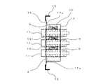
従来の配電盤としては、例えば、図5および図6に示すものがある。図5は断面側面図を示し、図6は図5のVI−VI線における要部断面平面図を示す。
これら各図において、1は閉鎖型配電盤等の配電盤であり、遮断器室2、水平母線室3、垂直母線室4等に区画されている。5は遮断器室2が複数段、例えば4段構成とされ、各段にそれぞれ設けられた台車床板である。6は各台車床板5に挿着され、コンビネーションユニット7が搭載されたコンビネーション台車である。8は水平母線室3に配置された水平母線である。9は一端が水平母線8と接続され、垂直母線室4に配置された各コンビネーションユニット7に電力を分配する垂直母線である。10は垂直母線9を支持する垂直母線支持具である。11は碍管である。パワーヒューズ7aとVMC(真空コネクタ)の組合わせでコンビネーションユニット7を構成する。
Examples of conventional switchboards include those shown in FIGS. 5 and 6. FIG. 5 shows a cross-sectional side view, and FIG. 6 shows a cross-sectional plan view of an essential part taken along line VI-VI in FIG.
In each of these drawings, 1 is a switchboard such as a closed type switchboard and is divided into a
12は垂直母線室4を構成するための一対の垂直母線室フレームであり、断面コ字状に形成され、前面側の突出部12aが短く、後面側の突出部12bが前面側の突出部12aより長く形成されている。一対の垂直母線室フレーム12間に垂直母線9が配置されている。13は一対の垂直母線室フレーム12の後面側の突出部12bの内方側に設けられた後面側垂直母線仕切り板であり、碍管11が貫挿されている。14は一対の垂直母線室フレーム12の前面側の突出部12aの外方側に設けられた前面側垂直母線仕切り板であり、碍子11が貫挿されている。これら一対の垂直母線室フレーム12、後面側垂直母線仕切り板13、前面側垂直母線仕切り板14により、前後左右が仕切られた構造の垂直母線室4が構成されている。
以上のように構成された閉鎖型配電盤1において、後面側垂直母線仕切り板13が垂直母線室フレーム12の後面側の突出部12bの内方側に取り付けられている理由としては、閉鎖型配電盤1を組み立てる際、閉鎖型配電盤1の後面側を下向きに寝かせて組み立てられていく。したがって、最初に閉鎖型配電盤1の箱体フレームに取り付けられた垂直母線室フレーム12の後面側の突出部12bの内方側に後面側垂直母線仕切り板13を取り付けるという組み立て手順によるものである。そして、前面側垂直母線仕切り板14は垂直母線室フレーム12の前面側の突出部12aの外方側に取り付けられる。
In the closed
また、垂直母線室フレーム12は、後面側垂直母線仕切り板13、前面側垂直母線仕切り板14の板厚よりも厚くして垂直母線室4の強度を高めている。
The vertical
上述した従来の配電盤においては、垂直母線室4内の垂直母線9や垂直母線支持具10の保守や点検、あるいは取替え等を行う場合には、前面側垂直母線仕切り板14を垂直母線室フレーム12の前面側の突出部12aから取り外す必要がある。
このように、前面側垂直母線仕切り板14を垂直母線室フレーム12の前面側の突出部12aから取り外すためには、台車床板10も取り外す必要があり、多大の作業時間および労力を要するという課題がある。
In the conventional switchboard described above, when the
Thus, in order to remove the front side vertical bus-
これは後面側垂直母線仕切り板13が垂直母線室フレーム12の後面側の突出部12bの内方側に取り付けられてあるためであり、その後面側垂直母線仕切り板13を取り外すことができない。その結果として、前面側垂直母線仕切り板14を取り外すしかないためである。
This is because the rear surface side vertical bus
この発明は上記のような課題を解決するためになされたものであり、簡単な構成で垂直母線室内の保守、点検を容易に行うことができる配電盤を提供することを目的とする。 The present invention has been made to solve the above-described problems, and an object thereof is to provide a switchboard that can easily perform maintenance and inspection in a vertical busbar room with a simple configuration.
この発明に係わる配電盤は、垂直母線室に配置された垂直母線を有する配電盤において、前記垂直母線を挟んで相対向し、前記垂直母線室のベースとなる一対の垂直母線室フレームと、前記垂直母線室フレームの後面側に取り付けられ碍管が貫挿される前面側垂直母線仕切り板と、前記垂直母線室フレームに支持され、前記碍管が貫挿されるとともに前記垂直母線を覆うよう断面コ字状に形成された後面側垂直母線仕切り板を設けたものである。 Switchboard according to the invention, in a switchboard having a vertical generatrix disposed perpendicularly busbar chamber, the opposite to each other across the vertical bus, and a pair of vertical busbar chamber frame as a base of the vertical busbar chamber, the vertical generatrices A front-side vertical busbar partition plate that is attached to the rear surface side of the chamber frame and through which the soot pipe is inserted , and is supported by the vertical busbar chamber frame, and is formed in a U-shaped cross section so as to penetrate the soot pipe and cover the vertical busbar. A rear-side vertical busbar partition plate is provided.
この発明に係わる配電盤は、簡単な構成で垂直母線室内の保守、点検を容易に行うことができる配電盤を得ることができる。 The switchboard according to the present invention can provide a switchboard that can be easily maintained and inspected in the vertical bus room with a simple configuration.
実施の形態1.
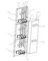
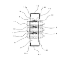
以下、この発明の実施の形態1を図1および図2に基づいて説明する。図1はこの発明の実施の形態1に係わる配電盤を示す要部断面平面図である。図2はこの発明の実施の形態1に係わる配電盤を示す要部斜視図である。なお、図2は遮断器室2が例えば3段構成とされる場合に対応した実施の形態となっている。
A first embodiment of the present invention will be described below with reference to FIGS. 1 is a cross-sectional plan view of an essential part showing a switchboard according to
これら各図において、9は垂直母線すなわち分岐母線、10は垂直母線支持具、11は碍管である。15は垂直母線9を挟んで相対向し、垂直母線室4すなわち分岐母線室のベースとなる一対の垂直母線室フレームすなわち分岐母線室フレームであり、例えば断面L字状からなる。16は垂直母線室フレーム15の後面側に取り付けられた前面側垂直母線仕切り板すなわち分岐母線仕切り板、17は垂直母線室フレーム15に支持され、垂直母線9を覆うよう断面コ字状に形成された後面側垂直母線仕切り板であり、後面側垂直母線仕切り板17は例えば取付フランジ17aおよび碍管11を通す貫挿穴17bを有し、その取付フランジ17aを前面側垂直母線仕切り板16に取り付け、その前面側垂直母線仕切り板16を介して垂直母線室フレーム15に支持される場合を示している。
In these drawings, 9 is a vertical bus, that is, a branch bus, 10 is a vertical bus support, and 11 is a soot tube.
なお、垂直母線室フレーム15の板厚は、前面側垂直母線仕切り板16および後面側垂直母線仕切り板17の板厚より厚く構成して垂直母線室4を支えるための必要な強度を確保している。また、必要な強度を確保しつつ板厚の厚い材料を極力少なくするため、垂直母線室フレーム15は必要最小限の例えば断面L字状で構成している。
Note that the plate thickness of the vertical
次に動作について説明する。上述した実施の形態1による配電盤においては、組み立て手順としては、閉鎖型配電盤1を組み立てる際、閉鎖型配電盤1の前面側を下向きに寝かせて組み立てて行くことで、組み立て作業性が悪化することも無い。すなわち、最初に閉鎖型配電盤1の箱体フレームに取り付けられた断面L字状の一対の垂直母線室フレーム15の後面側に前面側垂直母線仕切り板16を取り付ける。そして、断面コ字状の後面側垂直母線仕切り板17はその取付フランジ17aを前面側垂直母線仕切り板16に取り付けることにより、垂直母線室フレーム15に前面側垂直母線仕切り板16を介して支持される。
Next, the operation will be described. In the switchboard according to
ところで、垂直母線室4内の垂直母線9や垂直母線支持具10の保守や点検、あるいは取替え等を行う場合には、後面側垂直母線仕切り板17を取り外すだけでよく、上述した従来のように、台車床板10を取り外す必要が全くなくなり、多大の作業時間および労力を要することなく、垂直母線9や垂直母線支持具10の保守や点検、あるいは取替え等を簡単に容易に行うことができる。
By the way, when performing maintenance, inspection, replacement, etc. of the
また、垂直母線室フレーム15は、上述した従来のように、板厚の厚い断面コ字状で大きな垂直母線室フレーム12ではなく、垂直母線室4を支えるための必要な強度を確保しつつ板厚の厚い材料を極力少なくするため、垂直母線室フレーム15は必要最小限の例えば断面L字状の大きさで構成している。したがって、材料費の節減を図ることができるとともに重量も軽量化することができる。
Further, the vertical
実施の形態2.
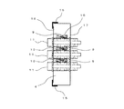
この発明の実施の形態2を図3に基づいて説明する。図3はこの発明の実施の形態2に係わる配電盤を示す要部断面平面図である。
A second embodiment of the present invention will be described with reference to FIG. FIG. 3 is a cross-sectional plan view of an essential part showing a switchboard according to
上述した実施の形態1においては、後面側垂直母線仕切り板17はその取付フランジ17aを前面側垂直母線仕切り板16に取り付けることにより、垂直母線室フレーム15に前面側垂直母線仕切り板16を介して支持される場合について述べたが、この実施の形態2においては、後面側垂直母線仕切り板17はその取付フランジ17aを垂直母線室フレーム15に取り付けて支持されるようにしたものであり、上述した実施の形態1と同様の効果を奏する。
In the first embodiment described above, the rear vertical
実施の形態3.
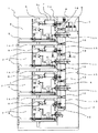
この発明の実施の形態3を図4に基づいて説明する。図4はこの発明の実施の形態3に係わる配電盤を示す要部断面平面図である。
A third embodiment of the present invention will be described with reference to FIG. 4 is a cross-sectional plan view of a main part showing a switchboard according to
上述した実施の形態2においては、後面側垂直母線仕切り板17はその取付フランジ17aを垂直母線室フレーム15に取り付けて支持される場合について述べたが、この実施の形態3においては、後面側垂直母線仕切り板17の取付フランジ17aを設けておらず、断面コ字状の後面側垂直母線仕切り板17の遮断器室2側に突出する面を断面L字状の垂直母線室フレーム15の後面側に突出する部分に取り付けて支持されるようにしたものであり、上述した各実施の形態と同様の効果を奏する。
なお、上記の各実施の形態では分岐母線が垂直母線の場合について説明したが、分岐母線がケーブルの場合であってもよい。
In the second embodiment described above, the case where the rear vertical
In each of the above embodiments, the case where the branch bus is a vertical bus has been described. However, the branch bus may be a cable.
この発明は、簡単な構成で垂直母線室内の保守、点検を容易に行うことができる配電盤の実現に好適である。 The present invention is suitable for realizing a switchboard that can be easily maintained and inspected in a vertical bus room with a simple configuration.
1 配電盤 4 垂直母線仕切り板
9 垂直母線 10 垂直母線支持具
15 垂直母線室フレーム 16 前面側垂直母線仕切り板
17 後面側垂直母線仕切り板
DESCRIPTION OF
Claims (4)
Priority Applications (1)
| Application Number | Priority Date | Filing Date | Title |
|---|---|---|---|
| JP2009141230A JP5421663B2 (en) | 2009-06-12 | 2009-06-12 | switchboard |
Applications Claiming Priority (1)
| Application Number | Priority Date | Filing Date | Title |
|---|---|---|---|
| JP2009141230A JP5421663B2 (en) | 2009-06-12 | 2009-06-12 | switchboard |
Publications (2)
| Publication Number | Publication Date |
|---|---|
| JP2010288397A JP2010288397A (en) | 2010-12-24 |
| JP5421663B2 true JP5421663B2 (en) | 2014-02-19 |
Family
ID=43543675
Family Applications (1)
| Application Number | Title | Priority Date | Filing Date |
|---|---|---|---|
| JP2009141230A Active JP5421663B2 (en) | 2009-06-12 | 2009-06-12 | switchboard |
Country Status (1)
| Country | Link |
|---|---|
| JP (1) | JP5421663B2 (en) |
Families Citing this family (3)
| Publication number | Priority date | Publication date | Assignee | Title |
|---|---|---|---|---|
| JP6010783B2 (en) * | 2012-07-26 | 2016-10-19 | 日東工業株式会社 | DC power supply cabinet |
| CN103372827B (en) * | 2013-07-24 | 2015-03-18 | 镇江默勒电器有限公司 | Vertical line installation positioning tool |
| KR200478916Y1 (en) | 2015-04-03 | 2015-12-01 | 윤여관 | MCC with Protecting Case |
Family Cites Families (1)
| Publication number | Priority date | Publication date | Assignee | Title |
|---|---|---|---|---|
| JPS4222820Y1 (en) * | 1965-06-23 | 1967-12-25 |
-
2009
- 2009-06-12 JP JP2009141230A patent/JP5421663B2/en active Active
Also Published As
| Publication number | Publication date |
|---|---|
| JP2010288397A (en) | 2010-12-24 |
Similar Documents
| Publication | Publication Date | Title |
|---|---|---|
| US6881898B2 (en) | Remote distribution cabinet | |
| KR101336969B1 (en) | Multi motor control centerfor a large number of loads | |
| CN101553964B (en) | Multiphase line fuse module | |
| JP5421663B2 (en) | switchboard | |
| KR20130005426U (en) | Block-type bus bar connecting device | |
| KR101642855B1 (en) | Electric wiring apparatus for dual multi distribution panelboard | |
| JP6366135B2 (en) | Distribution board cabinet, distribution board, and distribution board manufacturing method | |
| US3840785A (en) | Insulative modular mounting panels for electrical switchboards | |
| CA2849322A1 (en) | Molded case circuit breaker capable of withstanding short circuit conditions | |
| JP2012147566A (en) | Metal-enclosed switch gear | |
| CN1829019B (en) | Switchboard and manufacturing method thereof | |
| JP2019047579A (en) | switchboard | |
| JP4566136B2 (en) | Switchgear | |
| JP6562755B2 (en) | Switchgear | |
| US20160345457A1 (en) | Data rack support and wire management system and methods for using the same | |
| US7224577B2 (en) | Mounting plate system | |
| JP7090525B2 (en) | Metal closed switchboard | |
| CN1765039B (en) | Switching device | |
| JP2006238562A (en) | Plug-in distribution board | |
| JP2013215062A (en) | Metal closed switchgear | |
| JP7049896B2 (en) | Distribution board | |
| JP5629175B2 (en) | Cabinet rack with separable posts | |
| JPH0265607A (en) | Low voltage enclosed switchboard | |
| KR20170016574A (en) | Apparatus for supporting circuit breaker | |
| JP6556408B1 (en) | Switchgear |
Legal Events
| Date | Code | Title | Description |
|---|---|---|---|
| A621 | Written request for application examination |
Free format text: JAPANESE INTERMEDIATE CODE: A621 Effective date: 20120605 |
|
| A977 | Report on retrieval |
Free format text: JAPANESE INTERMEDIATE CODE: A971007 Effective date: 20130705 |
|
| A131 | Notification of reasons for refusal |
Free format text: JAPANESE INTERMEDIATE CODE: A131 Effective date: 20130716 |
|
| A521 | Request for written amendment filed |
Free format text: JAPANESE INTERMEDIATE CODE: A523 Effective date: 20130830 |
|
| TRDD | Decision of grant or rejection written | ||
| A01 | Written decision to grant a patent or to grant a registration (utility model) |
Free format text: JAPANESE INTERMEDIATE CODE: A01 Effective date: 20131112 |
|
| A61 | First payment of annual fees (during grant procedure) |
Free format text: JAPANESE INTERMEDIATE CODE: A61 Effective date: 20131122 |
|
| R151 | Written notification of patent or utility model registration |
Ref document number: 5421663 Country of ref document: JP Free format text: JAPANESE INTERMEDIATE CODE: R151 |
|
| R250 | Receipt of annual fees |
Free format text: JAPANESE INTERMEDIATE CODE: R250 |
|
| R250 | Receipt of annual fees |
Free format text: JAPANESE INTERMEDIATE CODE: R250 |
|
| R250 | Receipt of annual fees |
Free format text: JAPANESE INTERMEDIATE CODE: R250 |
|
| R250 | Receipt of annual fees |
Free format text: JAPANESE INTERMEDIATE CODE: R250 |
|
| R250 | Receipt of annual fees |
Free format text: JAPANESE INTERMEDIATE CODE: R250 |
|
| R250 | Receipt of annual fees |
Free format text: JAPANESE INTERMEDIATE CODE: R250 |
|
| R250 | Receipt of annual fees |
Free format text: JAPANESE INTERMEDIATE CODE: R250 |
|
| R250 | Receipt of annual fees |
Free format text: JAPANESE INTERMEDIATE CODE: R250 |
|
| R250 | Receipt of annual fees |
Free format text: JAPANESE INTERMEDIATE CODE: R250 |
|
| R250 | Receipt of annual fees |
Free format text: JAPANESE INTERMEDIATE CODE: R250 |