JP5421069B2 - Shielding device - Google Patents
Shielding device Download PDFInfo
- Publication number
- JP5421069B2 JP5421069B2 JP2009252349A JP2009252349A JP5421069B2 JP 5421069 B2 JP5421069 B2 JP 5421069B2 JP 2009252349 A JP2009252349 A JP 2009252349A JP 2009252349 A JP2009252349 A JP 2009252349A JP 5421069 B2 JP5421069 B2 JP 5421069B2
- Authority
- JP
- Japan
- Prior art keywords
- rail
- bottom rail
- shaft
- clutch
- drive shaft
- Prior art date
- Legal status (The legal status is an assumption and is not a legal conclusion. Google has not performed a legal analysis and makes no representation as to the accuracy of the status listed.)
- Active
Links
- 238000004804 winding Methods 0.000 claims description 52
- 230000005540 biological transmission Effects 0.000 claims description 32
- 230000002265 prevention Effects 0.000 claims description 17
- 230000003028 elevating effect Effects 0.000 claims description 6
- 239000000463 material Substances 0.000 claims description 6
- 239000000725 suspension Substances 0.000 claims description 4
- 230000002093 peripheral effect Effects 0.000 description 12
- 230000000694 effects Effects 0.000 description 7
- 239000004744 fabric Substances 0.000 description 6
- 230000000630 rising effect Effects 0.000 description 4
- 230000000903 blocking effect Effects 0.000 description 2
- 239000002184 metal Substances 0.000 description 2
- 230000004048 modification Effects 0.000 description 2
- 238000012986 modification Methods 0.000 description 2
- 241000238631 Hexapoda Species 0.000 description 1
- 238000004891 communication Methods 0.000 description 1
- 238000003780 insertion Methods 0.000 description 1
- 230000037431 insertion Effects 0.000 description 1
- 238000000034 method Methods 0.000 description 1
- 230000000717 retained effect Effects 0.000 description 1
- 229920003002 synthetic resin Polymers 0.000 description 1
- 239000000057 synthetic resin Substances 0.000 description 1
- 239000013585 weight reducing agent Substances 0.000 description 1
Images


Landscapes
- Blinds (AREA)
Description
この発明は、ボトムレールと中間レールとをそれぞれ昇降可能としたプリーツスクリーン、横型ブラインド、たくし上げカーテン等で、スクリーン、スラット、カーテン等を昇降する昇降装置に関するものである。 The present invention relates to an elevating device that elevates and lowers a screen, a slat, a curtain, and the like with a pleated screen, a horizontal blind, a hoisting curtain, and the like that can raise and lower a bottom rail and an intermediate rail, respectively.
プリーツスクリーンは、上下方向にジクザグ状に折り曲げ可能としたスクリーンをヘッドボックスから吊下支持し、そのスクリーンを操作装置により昇降して採光量を適宜に調節するものである。 The pleated screen suspends and supports a screen that can be bent in a zigzag shape in the vertical direction, and adjusts the amount of light appropriately by moving the screen up and down with an operating device.
このようなプリーツスクリーンの一種類として、ボトムレールと中間レールとを備え、ヘッドボックスから吊下支持される上部スクリーンの下端に中間レールを取着し、中間レールから吊下支持される下部スクリーンの下端にボトムレールを取着したものがある。上部スクリーンは、例えばレース生地等の光を一部透過させる半透過性の生地で形成され、下部スクリーンは遮光性を備えた生地で形成される。 As one type of such a pleated screen, a bottom rail and an intermediate rail are provided, an intermediate rail is attached to the lower end of the upper screen supported by suspension from the head box, and the lower screen supported by suspension from the intermediate rail. Some have a bottom rail attached to the bottom. The upper screen is made of a semi-permeable cloth that partially transmits light, such as a lace cloth, and the lower screen is made of a cloth having a light shielding property.
そして、中間レール及びボトムレールを昇降する操作装置がそれぞれ備えられ、各操作装置により中間レール及びボトムレールをそれぞれ独立して昇降可能となっている。
このような構成により、ボトムレール及び中間レールを下限まで下降させると、半透過性の上部スクリーンで窓面を覆うことが可能であり、ボトムレールを下限まで下降させるとともに中間レールを上限まで引き上げれば、遮光性を備えた下部スクリーンで窓面を覆うことが可能である。
And the operation device which raises / lowers an intermediate rail and a bottom rail is each provided, and the intermediate rail and the bottom rail can be raised / lowered independently by each operation device.
With such a configuration, when the bottom rail and the intermediate rail are lowered to the lower limit, it is possible to cover the window surface with a semi-permeable upper screen, and the bottom rail is lowered to the lower limit and the intermediate rail can be raised to the upper limit. For example, it is possible to cover the window surface with a lower screen having light shielding properties.
また、ボトムレールを下限まで下降させるとともに中間レールを中間位置まで下降させれば、窓面の上部を半透過性のスクリーンで覆い、窓面の下部を遮光性のスクリーンで覆うこともできる。 If the bottom rail is lowered to the lower limit and the intermediate rail is lowered to the intermediate position, the upper part of the window surface can be covered with a semi-transparent screen and the lower part of the window surface can be covered with a light-shielding screen.
特許文献1に記載されたプリーツスクリーンでは、一本の操作コードの操作により、中間レールとボトムレールとの同時引き上げ操作及び同時下降動作が可能であるが、中間レールを中間位置に保持した状態でボトムレールを昇降操作することはできない。また、ボトムレール及び中間レールを自重降下により下降操作することはできないため、下降操作が煩雑となる。
In the pleated screen described in
一方、中間レールの引き上げ操作は、巻取りパイプに昇降コードを逆巻する操作を行う必要があるため、その操作手順が操作者にとってわかり難い。
特許文献2に記載されたプリーツスクリーンでは、中間レール及びボトムレールの引き上げ操作と、中間レール及びボトムレールの下降操作とを別の操作手段で行う必要があるため、引き上げ操作と下降操作とを連続して行うとき、その操作が煩雑となる。
On the other hand, the lifting operation of the intermediate rail requires an operation of reversely winding the lifting / lowering cord around the winding pipe, and the operation procedure is difficult for the operator to understand.
In the pleated screen described in
また、中間レールとボトムレールの下降操作をそれぞれ独立して行うことができるが、引き上げ操作時には、中間レールのみの引き上げ操作及びボトムレールのみの引き上げ操作を独立して行うことができない。従って、中間レール及びボトムレールを所望高さに昇降するための昇降操作が煩雑となる。 Further, the lowering operation of the intermediate rail and the bottom rail can be performed independently, but during the lifting operation, the lifting operation of only the intermediate rail and the lifting operation of only the bottom rail cannot be performed independently. Therefore, the raising / lowering operation for raising / lowering the intermediate rail and the bottom rail to a desired height becomes complicated.
特許文献3に記載されたプリーツスクリーンでは、中間レール及びボトムレールの引き上げ操作と、中間レール及びボトムレールの下降操作とを別の操作手段で行う必要がある。また、ボトムレールの引き上げ操作を行うためには、あらかじめ中間レールを上限まで引き上げる必要があるので、ボトムレール及び中間レールを所望高さに昇降するための操作が煩雑となる。
In the pleated screen described in
この発明の目的は、中間レールとボトムレールを共通の操作コードでそれぞれ独立して昇降操作可能とした遮蔽装置を提供することにある。 An object of the present invention is to provide a shielding device in which an intermediate rail and a bottom rail can be moved up and down independently with a common operation cord.
請求項1では、ヘッドボックスから中間レールとボトムレールとを昇降可能に吊下支持し、少なくとも中間レールとボトムレールとの間に遮蔽材を吊下支持し、前記中間レールを吊下支持する第一の昇降コードと、前記ボトムレールを吊下支持する第二の昇降コードを前記ヘッドボックス内で巻取り、あるいは巻き戻して前記中間レールとボトムレールを昇降することにより前記遮蔽材を上下方向に引き出しあるいは畳み込み可能とした昇降装置を備えた遮蔽装置において、前記昇降装置は、前記ヘッドボックスから垂下される無端状の操作コードと、前記操作コードの一方への操作により前記中間レールを昇降可能とし、他方への操作により前記ボトムレールを昇降可能とした選択操作手段とを備え、前記選択操作手段は、前記ボトムレールで前記中間レールを押し上げて、該ボトムレールと中間レールとを一括して引き上げ可能とした。 According to a first aspect of the present invention, the intermediate rail and the bottom rail are suspended and supported from the head box so as to be lifted and lowered, and at least the shielding material is suspended and supported between the intermediate rail and the bottom rail. One lifting cord and a second lifting cord for hanging and supporting the bottom rail are wound or unwound in the head box to raise and lower the intermediate rail and the bottom rail, thereby moving the shielding material in the vertical direction. In the shielding device provided with an elevating device that can be pulled out or folded, the elevating device can elevate the intermediate rail by operating an endless operation cord hanging from the head box and one of the operation cords. Selection operation means for allowing the bottom rail to be moved up and down by an operation to the other, and the selection operation means includes the bottom rail. In pushing up the intermediate rail, and allows pulling collectively and the bottom rail and the intermediate rail.
請求項2では、前記昇降装置は、前記ボトムレールと中間レールを一括して引き上げるとき、前記中間レールを吊下支持する第一の昇降コードを、前記ヘッドボックス内の第一の巻取軸に巻き取る中間クラッチを備えた。 According to a second aspect of the present invention, when the lifting device pulls up the bottom rail and the intermediate rail in a lump, the first lifting cord that supports the suspension of the intermediate rail is attached to the first winding shaft in the head box. An intermediate clutch for winding is provided.
請求項3では、前記昇降装置は、前記第一の昇降コードを巻き取る第一の巻取軸と、前記ボトムレールを吊下支持する第二の昇降コードを巻き取る第二の巻取軸と、前記第一の巻取軸を回転駆動する第一の駆動軸と、前記第二の巻取軸を回転駆動する第二の駆動軸と
を備え、前記中間クラッチは、前記第一の巻取軸に前記中間レールの荷重が作用しないとき、前記第二の駆動軸の回転を前記第一の駆動軸に伝達する伝達装置を備えた。
In the third aspect of the present invention, the lifting device includes a first winding shaft that winds up the first lifting cord, and a second winding shaft that winds up the second lifting cord that supports the bottom rail. A first drive shaft that rotationally drives the first winding shaft, and a second drive shaft that rotationally drives the second winding shaft, and the intermediate clutch includes the first winding shaft A transmission device is provided for transmitting the rotation of the second drive shaft to the first drive shaft when the load of the intermediate rail does not act on the shaft.
請求項4では、前記伝達装置は、前記第二の駆動軸と一体に回転する駆動ギヤと、前記駆動ギヤに噛み合う被動ギヤと、前記第一の巻取軸に荷重が作用しないとき、前記被動ギヤと前記第一の駆動軸を連結するカム機構とを備えた。 According to a fourth aspect of the present invention, the transmission device includes a driving gear that rotates integrally with the second driving shaft, a driven gear that meshes with the driving gear, and a load that does not act on the first winding shaft. A cam mechanism for connecting the gear and the first drive shaft;
請求項5では、前記中間クラッチには、前記被動ギヤと前記第一の駆動軸が連結されている状態で、前記中間レールの自重降下を阻止するブレーキ装置を備えた。
請求項6では、前記中間クラッチには、前記第二の駆動軸のボトムレール引き上げ方向の回転のみを前記駆動ギヤに伝達するワンウェイクラッチと、前記ワンウェイクラッチと前記第二の駆動軸との間に介在され、前記第二の駆動軸から前記ワンウェイクラッチに伝達される回転トルクを制限する伝達トルク制限装置とを備えた。
According to a fifth aspect of the present invention, the intermediate clutch includes a brake device that prevents the intermediate rail from dropping its own weight in a state where the driven gear and the first drive shaft are connected.
According to a sixth aspect of the present invention, the intermediate clutch includes a one-way clutch that transmits only the rotation of the second drive shaft in the bottom rail pulling direction to the drive gear, and between the one-way clutch and the second drive shaft. And a transmission torque limiting device that limits the rotational torque transmitted from the second drive shaft to the one-way clutch.
請求項7では、前記昇降装置は、前記中間レール及びボトムレールの引き上げ操作後に前記操作コードを手放したとき、前記中間レール及びボトムレールの自重降下防止動作に移行するストッパー装置と、前記中間レール及びボトムレールの一括引き上げ操作後に前記ストッパー装置によるボトムレールの自重降下防止動作を解除したとき、前記中間レールの自重降下防止動作の同時解除を阻止する自重降下制限装置とを備えた。 In the seventh aspect of the present invention, when the lifting and lowering device releases the operation cord after the intermediate rail and the bottom rail are lifted, a stopper device that shifts to a self-weight drop prevention operation of the intermediate rail and the bottom rail, the intermediate rail, A self-weight drop limiting device for preventing simultaneous release of the self-weight drop prevention operation of the intermediate rail when the self-weight drop prevention operation of the bottom rail by the stopper device is canceled after the bottom rail collective pulling operation;
請求項8では、前記ストッパー装置は、前記第一及び第二の駆動軸を前記中間レール及びボトムレールの引き上げ方向に回転させたとき、自重降下防止動作を解除可能とし、前記自重降下制限装置は、前記ボトムレールの自重降下防止動作の解除時の前記第二の駆動軸の回転角を制限する制限手段と、前記第二の駆動軸が回転された後に前記第一の駆動軸を回転させる空転手段とを備えた。 In the eighth aspect of the present invention, when the first and second drive shafts are rotated in the pulling direction of the intermediate rail and the bottom rail, the stopper device can release the self-weight drop prevention operation, Limiting means for restricting the rotation angle of the second drive shaft when releasing the operation of preventing the bottom rail from dropping its own weight, and idle rotation for rotating the first drive shaft after the second drive shaft is rotated. Means.
本発明によれば、中間レールとボトムレールを共通の操作コードでそれぞれ独立して昇降操作可能とした遮蔽装置を提供することができる。 According to the present invention, it is possible to provide a shielding device in which the intermediate rail and the bottom rail can be moved up and down independently with a common operation cord.
(第一の実施形態)
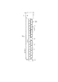
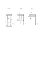
以下、この発明を具体化した第一の実施形態を図面に従って説明する。図1〜図3に示すプリーツスクリーンは、ヘッドボックス1から上部スクリーン2が吊下支持され、上部スクリーン2の下端に中間レール3が取着されている。前記中間レール3から下部スクリーン4が吊下支持され、下部スクリーン4の下端にボトムレール5が取着されている。
(First embodiment)
Hereinafter, a first embodiment of the present invention will be described with reference to the drawings. In the pleated screen shown in FIGS. 1 to 3, an
前記上部スクリーン2はレース生地等の半透過性の生地をジグザグ状に折り畳み可能としたものであり、下部スクリーン4は遮光性を備えた生地をジグザグ状に折り畳み可能としたものである。
The
前記上部スクリーン2の幅方向両側には第一及び第二の昇降コード6,7が挿通され、第一の昇降コード6の下端は前記中間レール3に取着されている。第二の昇降コード7は、中間レール3を貫通し、さらに下部スクリーン4に挿通され、下端が前記ボトムレール5に取着されている。
First and second lifting / lowering
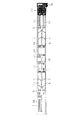
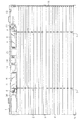
前記第一及び第二の昇降コード6,7の上端部は、前記ヘッドボックス1内で支持部材8に回転可能に支持される第一及び第二の巻取軸9,10にそれぞれ巻着されている。すなわち、図3に示すように、第一及び第二の巻取軸9,10はヘッドボックス1内において前記第一及び第二の昇降コード6,7の上方位置で水平方向に並列する状態で支持部材8に回転可能に支持されている。
The upper ends of the first and second lifting / lowering
そして、第一の昇降コード6の上端部が第一の巻取軸9に巻着され、第二の昇降コード7の上端部が第二の巻取軸10に巻着され、第一及び第二の昇降コード6,7は、第一及び第二の巻取軸9,10に対し互いに逆方向に巻着されている。また、第一及び第二の昇降コード6,7は、第一及び第二の巻取軸9,10の回転に基づいて、螺旋状に巻き取られ、あるいは巻戻されるようになっている。
And the upper end part of the 1st raising /
前記第一の巻取軸9には六角棒状の第一の駆動軸11が相対回転不能に挿通され、第二の巻取軸10には同じく六角棒状の第二の駆動軸12が相対回転不能に挿通されている。そして、第一の駆動軸11が前記第一の昇降コード6の巻取り方向に回転されると、第一の巻取軸9に第一の昇降コード6が巻き取られ、第二の駆動軸12が前記第二の昇降コード7の巻取り方向に回転されると、第二の巻取軸10に第二の昇降コード7が巻き取られるようになっている。
A hexagonal bar-shaped
前記ヘッドボックス1の一方の端部には、前記第一及び第二の駆動軸11,12を回転駆動するための操作装置13が取着されている。図4に示すように、前記操作装置13のケース14内の基端側にはプーリー15が回転可能に支持され、そのプーリー15には無端状のボールチェーン16が掛装されて下方へ垂下されている。そして、ボールチェーン16の操作によりプーリー15を回転駆動可能となっている。
An operating
前記プーリー15には歯車15aが一体に形成され、その歯車15aに前記ケース14に回転可能に支持された伝達歯車17が噛み合わされている。従って、プーリー15が回転されると、伝達歯車17が回転される。
A
前記伝達歯車17には、同伝達歯車17の径方向両側において前記ケース14に回転可能に支持された一対の第一及び第二のクラッチ歯車18,19が噛み合わされている。そして、前記伝達歯車17が回転されると、第一及び第二のクラッチ歯車18,19が同方向に回転される。
A pair of first and second clutch gears 18 and 19 that are rotatably supported by the
前記ケース14の先端側には、同一構成の第一及び第二の伝達クラッチ20,21が収容され、その第一及び第二の伝達クラッチ20,21の入力軸22が前記第一及び第二のクラッチ歯車18,19の中心部に嵌着されている。従って、前記第一及び第二のクラッチ歯車18,19が回転されると、第一及び第二の伝達クラッチ20,21の入力軸22が同方向に回転されるようになっている。
The first and
前記第一及び第二の伝達クラッチ20,21は、入力軸22の一方向の回転のみを各出力軸23に伝達する公知の機能を備え、伝達する回転方向は互いに逆方向である。そして、第一の伝達クラッチ20の出力軸23に前記第一の駆動軸11の端部が嵌着され、第二の伝達クラッチ21の出力軸23に前記第二の駆動軸12の端部が嵌着されている。
The first and
このような構成により、ボールチェーン16を例えば図2に示す矢印A方向に操作すると、第二の駆動軸12のみが回転されて、第二の巻取軸10が第二の昇降コード7の巻取り方向に回転される。
With such a configuration, when the
また、ボールチェーン16を図2に示す矢印B方向に操作すると、第一の駆動軸11のみが回転されて、第一の巻取軸9が第一の昇降コード6の巻取り方向に回転される。
前記第一及び第二の駆動軸11,12は、前記ヘッドボックス1の中間部においてストッパー装置24に挿通されている。このストッパー装置24は、前記中間レール3若しくはボトムレール5の引き上げ操作の後にボールチェーン16を手放したとき、中間レール3及びボトムレール5の自重降下を防止する公知の作用をなす。
When the
The first and
前記ストッパー装置24の具体的構成を説明すると、前記ストッパー装置24のケース25は前記ヘッドボックス1内に固定され、図5に示すように、二つの円筒部26a,26bが形成されている。そして、前記円筒部26a,26b内には第一のドラム27及び第二のドラム28が回転可能に保持されている。なお、第一及び第二のドラム27,28は円筒部26a,26bに対し互いに逆方向から挿入可能となっている。
A specific configuration of the
前記第一のドラム27には前記第一の駆動軸11が相対回転不能に挿通され、前記第二のドラム28には前記第二の駆動軸12が相対回転不能に挿通されている。そして、第一のドラム27は第一の駆動軸11と一体に回転し、第二のドラム28は第二の駆動軸12と一体に回転するようになっている。
The
前記円筒部26a,26bの内周面には、断面半円形のスライド溝29が前記第一及び第二の駆動軸11,12の軸方向に沿ってそれぞれ形成され、そのスライド溝29内に鋼球で形成されるクラッチボール30が同スライド溝29に沿って移動可能に支持されている。
A
前記第一及び第二のドラム27,28の外周面には、前記クラッチボール30を案内する断面半円形のガイド溝31が形成されている。そして、第一及び第二のドラム27,28が回転されると、前記クラッチボール30はスライド溝29に沿って移動しながら、ガイド溝31に沿って周回する。
A
前記第一及び第二のドラム27,28のガイド溝31は同一構成であり、前記ケース25に対し左右方向に入れ替えて取着することにより、第一及び第二のドラム27,28の回転方向の違いに対応している。前記第一のドラム27について、前記ガイド溝31の構成を図6に示す展開状態で説明する。
The
図6において、中間レール3が下降する方向に第一のドラム27が回転されるとき、前記クラッチボール30はガイド溝31に沿って相対的に矢印C方向に移動する。また、中間レール3が上昇する方向に第一のドラム27が回転するとき、前記クラッチボール30はガイド溝31に沿って相対的に矢印D方向に移動する。
In FIG. 6, when the
前記第一のドラム27の周面の両側部には下降溝32a,32bが形成され、中央部には上昇溝33が形成されている。前記上昇溝33には、クラッチボール30が上昇溝33内に位置する状態で第一のドラム27が中間レール3の下降方向に回動されるとき、僅かな回転の後にクラッチボール30の移動を阻止する係止部34が連通して形成されている。係止部34は周方向等間隔に4箇所形成されている。
また、クラッチボール30が係止部34に係合している状態から、第一のドラム27が中間レール3の上昇方向に回動されるとき、クラッチボール30は前記下降溝32a,32bのいずれかに案内される。
Further, when the
前記下降溝32a,32bには、クラッチボール30が下降溝32a,32bのいずれかに位置している状態から、第一のドラム27が中間レール3の上昇方向に回動されるとき、クラッチボール30を上昇溝33に案内する戻り溝35が周方向等間隔に4箇所形成されている。
When the
このような第一のドラム27を備えたストッパー装置24の動作を説明すると、ボールチェーン16の操作により第一の駆動軸11が第一の昇降コード6の巻取り方向に回転されて中間レール3が引き上げられるとき、クラッチボール30は上昇溝33内を矢印D方向に相対移動している。
The operation of the
中間レール3を所望高さまで引き上げた後、ボールチェーン16を手放すと、中間レール3の重量によりクラッチボール30は上昇溝33内を矢印C方向に移動して、係止部34に係合する。すると、クラッチボール30の矢印C方向の移動が阻止されて、第一のドラム27の回転が阻止され、中間レール3の自重降下が阻止される。
When the
この状態から、ボールチェーン16を操作して中間レール3を僅かに引き上げると、クラッチボール30は係止部34から下降溝32a,32bのいずれかに移動する。この状態でボールチェーン16を手放すと、クラッチボール30は下降溝32a,32bのいずれかを矢印C方向へ周回する状態となり、中間レール3が自重降下する。
From this state, when the
また、中間レール3が下限まで下降した後、あるいは下降動作中にボールチェーン16を中間レール3の引き上げ方向に操作すると、クラッチボール30は下降溝32a,32bのいずれかから戻り溝35を経て上昇溝33に移動する。そして、クラッチボール30が上昇溝33内を矢印D方向に周回して、中間レール3が引き上げられる。
Further, when the
前記ストッパー装置24では、第二のドラム28の動作により、ボトムレール5の昇降動作に対し、中間レール3の昇降動作に対する機能と同様な機能を備えている。
図1及び図3に示すように、前記ストッパー装置24の側方において、前記第一及び第二の駆動軸11,12はガバナー装置36,37にそれぞれ挿通されている。各ガバナー装置36,37は、前記第一及び第二の駆動軸11,12の回転速度を所定値以下に抑制して、中間レール3及びボトムレール5の自重降下時の下降速度を所定速度以下に抑制する。
The
As shown in FIGS. 1 and 3, on the side of the
前記ヘッドボックス1の他方の端部には、前記第二の巻取軸10からの第二の昇降コード7の最大巻戻し量を設定して、前記ボトムレール5の下限位置を設定する下限リミット装置38が配設されている。
A lower limit for setting the maximum rewinding amount of the second lifting /
図2に示すように、前記第一及び第二の昇降コード6,7の挿通位置において、前記上部スクリーン2及び下部スクリーン4の背面側にはピッチ保持コード39が配設されている。このピッチ保持コード39は、上部スクリーン2と下部スクリーン4の折り目のピッチを一定にするように動作する。
As shown in FIG. 2, a
次に、上記のように構成されたプリーツスクリーンの動作を説明する。ボールチェーン16を矢印A方向に引き下げると、第二の駆動軸12のみが回転されて第二の巻取軸10に第二の昇降コード7が巻き取られ、ボトムレール5が引き上げられる。そして、ボトムレール5を所望高さまで引き上げた後ボールチェーン16を手放すと、ストッパー装置24の自重降下防止動作により、ボトムレール5が所望高さに保持される。
Next, the operation of the pleated screen configured as described above will be described. When the
この状態から、ボールチェーン16を矢印A方向に引いた後に手放すと、ストッパー装置24の自重降下防止動作が解除され、ボトムレール5が自重降下する。
ボールチェーン16を矢印B方向に引き下げると、第一の駆動軸11のみが回転されて第一の巻取軸9に第一の昇降コード6が巻き取られ、中間レール3が引き上げられる。そして、中間レール3を所望高さまで引き上げた後ボールチェーン16を手放すと、ストッパー装置24の自重降下防止動作により、中間レール3が所望高さに保持される。
From this state, when the
When the
この状態から、ボールチェーン16を矢印B方向に引いた後に手放すと、ストッパー装置24の自重降下防止動作が解除され、中間レール3が自重降下する。
図7(a)に示すように、中間レール3が昇降範囲の中間に保持され、ボトムレール5が下限近傍に位置する状態からボトムレール5を引き上げるとき、同図(b)に示すように、ボトムレール5が中間まで引き上げられると、ボトムレール5が中間レール3を押し上げる状態となる。
From this state, when the
As shown in FIG. 7 (a), when the
次いで、ボトムレール5をさらに引き上げると、ボトムレール5とともに中間レール3が押し上げられ、同図(c)に示すように、ボトムレール5及び中間レール3を上限まで引き上げた状態でボールチェーン16を手放すと、ボトムレール5及び中間レール3がヘッドボックス1の直下に保持される。
Next, when the
この状態から、ボールチェーン16を矢印A方向に引いて手放すと、ストッパー装置24のボトムレール5の自重降下防止動作が解除されるため、ボトムレール5が自重降下する。
From this state, when the
このとき、中間レール3はボトムレール5とともに自重降下し、図7(b)に示す高さまで下降した後は、ストッパー装置24の中間レール3に対する自重降下防止動作が機能して、中間レール3が当該高さに保持される。
At this time, the
上記のように構成されたプリーツスクリーンでは、次に示す作用効果を得ることができる。
(1)共通のボールチェーン16の操作により、中間レール3及びボトムレール5を独立して昇降操作することができる。
(2)中間レール3及びボトムレール5を独立した自重降下動作により容易に下降操作することができる。
(3)ボトムレール5の引き上げ操作を行うとき、ボトムレール5で中間レール3を押し上げながら引き上げることができる。従って、ボトムレール5を引き上げることにより、中間レール3を一括して引き上げることができる。
(4)一括して引き上げたボトムレール5及び中間レール3を、ストッパー装置24の動作により所望の位置に保持することができる。
(5)ボトムレール5及び中間レール3を一括して引き上げた後、ボトムレール5を自重降下させるとき、ボトムレール5及び中間レール3を一括して下降させることができる。そして、ストッパー装置24の動作により、中間レール3の自重降下動作をボトムレール5による押し上げ開始位置で自動的に停止させることができる。
(第二の実施形態)
図8〜図13は第二の実施形態を示す。この実施形態は、ボトムレール5で中間レール3を押し上げるとき、第一の巻取軸9で中間レール3を吊下支持する第一の昇降コード6を巻き取って、第一の昇降コード6がヘッドボックス1内あるいは上部スクリーン2の折り目の間で弛まないようにする中間クラッチ41を備えたものである。中間クラッチ41以外の構成は、前記第一の実施形態と同様であり、第一の実施形態と同一構成部分は同一符号を付して詳細な説明を省略する。
In the pleated screen configured as described above, the following operational effects can be obtained.
(1) By operating the
(2) The
(3) When the
(4) The
(5) When the
(Second embodiment)
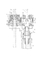
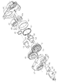
8 to 13 show a second embodiment. In this embodiment, when the
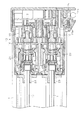
図8及び図9に示すように、一方の支持部材8の一側には中間クラッチ41が配設されている。前記中間クラッチ41は、図10及び図12に示すように、ケース42内の後部には駆動ドラム43が回転可能に支持され、その駆動ドラム43の中心部に形成された六角孔に前記第二の駆動軸12が相対回転不能に挿通されている。従って、駆動ドラム43は第二の駆動軸12と一体に回転する。
As shown in FIGS. 8 and 9, an
前記駆動ドラム43の先端部には内筒部44と外筒部45が形成され、その内筒部44の外周面に伝達軸46の基端部が回転可能に嵌合されている。前記伝達軸46の基端部外周面にはコイル状のスリップバネ47が嵌着され、そのスリップバネ47の一端は前記駆動ドラム43の係止溝48に係合している。そして、常にはスリップバネ47と伝達軸46との摩擦により、駆動ドラム43と伝達軸46とが一体に回転するようになっている。
An
前記伝達軸46の先端側において、前記ケース42には駆動ギヤ49が回転可能に支持され、その駆動ギヤ49と前記伝達軸46との間にはワンウェイクラッチ50が介在されている。
A
このワンウェイクラッチ50は、第二の駆動軸12及び前記伝達軸46がボトムレール5の引き上げ方向に回転されるとき、ロック状態となって前記駆動ギヤ49に同方向の回転トルクを伝達する。また、第二の駆動軸12及び前記伝達軸46がボトムレール5の下降方向に回転されるとき、フリー状態となって前記駆動ギヤ49に回転トルクを伝達しない。
When the
前記スリップバネ47は、前記駆動ギヤ49の回転が阻止された状態で第二の駆動軸12をボトムレール5の引き上げ方向に回転させるトルクが作用したとき、伝達軸46に対し駆動ドラム43を空回りさせて、ワンウェイクラッチ50の破損を防止するように動作する。
The
前記ケース42内の前部には、前記駆動ギヤ49に噛み合う被動ギヤ51が回転可能に支持され、その被動ギヤ51の中心部にはギヤ軸52が相対回転可能に挿通されている。また、ギヤ軸52と前記ケース42との間にはコイルスプリングで構成される切り替えバネ53が配設され、ケース42を支点とする切り替えバネ53の付勢力によりギヤ軸52は図10に示す矢印E方向に常時付勢されている。
A driven
前記ギヤ軸52の外周面にはT字状の係合突部54が形成され、前記被動ギヤ51の内周面にはギヤ軸52が回転しながら矢印E方向に移動したとき係合突部54に係合する係合凹部55が形成されている。そして、係合突部54が係合凹部55に係合すると、ギヤ軸52が被動ギヤ51と一体に回転するようになっている。
A T-shaped
前記ギヤ軸52の先端にはカム軸56の基端部が嵌着され、カム軸56がギヤ軸52と一体に回転するようになっている。前記カム軸56の外周面には径方向に線対称状に突出する突起57が形成されている。
The base end portion of the
前記カム軸56の先端部は、カム筒58の基端部に嵌合されている。前記カム筒58には、前記カム軸56の突起57を案内するガイド孔59が斜め方向に形成され、カム軸56はカム筒58に対し回転しながら第一の駆動軸11の軸方向に移動可能となっている。
The distal end portion of the
前記カム筒58の先端部は、前記第一の巻取軸9に嵌着され、カム筒58と第一の巻取軸9とは一体に回転するようになっている。また、前記カム軸56の中心部には六角孔60が形成され、その六角孔60に前記第一の駆動軸11が相対回転不能に挿通されている。なお、前記第一の駆動軸11は前記ギヤ軸52及びカム筒58の中心部に相対回転可能に挿通されている。
The tip of the
前記被動ギヤ51の基端側の周囲には、前記ケース42に回転不能に固定された金属製の摺動筒62の内周面に嵌着されるブレーキスプリング61が配設されている。前記ブレーキスプリング61は、捩じりコイルスプリングで構成され、その一端が前記被動ギヤ51に掛止めされ、被動ギヤ51が中間レール3の下降方向に回転されるとき、拡径されて前記摺動筒62との摩擦が増大し、被動ギヤ51の同方向の回転を阻止するようになっている(ブレーキ装置)。
A
また、前記ブレーキスプリング61は被動ギヤ51が中間レール3の引き上げ方向に回転されるとき、前記摺動筒62との摩擦が減少し、被動ギヤ51の同方向の回転を許容するようになっている。
Further, when the driven
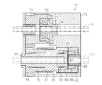
上記のように構成された中間クラッチ41では、第一の巻取軸9に中間レール3の荷重が作用している状態では、図10に示すように、カム軸56とカム筒58との作用によりカム軸56が矢印F方向に押圧されて移動している。この状態では、図13(a)に示すようにギヤ軸52の係合突部54と被動ギヤ51の係合凹部55との係合が解除され、被動ギヤ51とギヤ軸52とは独立して回転する。
In the intermediate clutch 41 configured as described above, when the load of the
この状態では、第二の駆動軸12がボトムレール5の引き上げ方向に回転されると、駆動ギヤ49及び被動ギヤ51が回転されるが、被動ギヤ51の回転はギヤ軸52に伝達されない。
In this state, when the
また、第一の駆動軸11が回転されると、カム軸56を介してギヤ軸52が回転されるが、その回転が被動ギヤ51に伝達されることはない。
一方、第二の駆動軸12がボトムレール5の引き上げ方向に回転されている状態で、第一の巻取軸9に中間レール3の荷重が作用しなくなると、切り替えバネ53の付勢力と、カム軸56及びカム筒58(カム機構)との作用により、ギヤ軸52が図10に示す矢印E方向に移動する。
When the
On the other hand, when the load of the
すると、図13(b)に示すように、ギヤ軸52の係合突部54が被動ギヤ51の係合凹部55に係合して、被動ギヤ51とギヤ軸52とが一体に回転する状態となり、駆動ギヤ49の回転に基づいて第一の駆動軸11及び第一の巻取軸9が中間レール3の引き上げ方向に回転される(伝達装置)。この結果、中間レール3とボトムレール5が同時に引き上げられる。
Then, as shown in FIG. 13B, the
次に、上記のような中間クラッチ41を備えたプリーツスクリーンの動作を説明する。
中間レール3を独立して昇降する場合及びボトムレール5を独立して昇降する場合の動作は、前記第一の実施形態と同様であり、中間クラッチ41は第一及び第二の駆動軸11,12の回転に対し、何ら影響しない。
Next, the operation of the pleated screen provided with the intermediate clutch 41 as described above will be described.
When the
ボトムレール5で中間レール3を押し上げて、ボトムレール5及び中間レール3を一括して引き上げるとき、第一の巻取軸9に中間レール3の荷重が作用しなくなる。すると、ギヤ軸52が図10に示す矢印E方向に移動して被動ギヤ51に係合して、同被動ギヤ51と一体に回転される。
When the
この結果、第一の巻取軸9が第一の昇降コード6の巻取り方向に回転され、第一の巻取軸9に第一の昇降コード6が巻き取られる。そして、ボトムレール5を所望高さまで引き上げてボールチェーン16を手放せば、ストッパー装置24の動作によりボトムレール5の自重降下が阻止され、中間レール3はボトムレール5上に保持される。
As a result, the first winding
ボトムレール5及び中間レール3を一括して引き上げた状態からボトムレール5を下降させる場合には、ボールチェーン16を図2に示す矢印A方向にわずかに引いて手放すと、ストッパー装置24の自重降下防止動作が解除され、ボトムレール5が自重降下する。
When the
このとき、ワンウェイクラッチ50の動作により、第二の駆動軸12の回転は駆動ギヤ49に伝達されない。
ボトムレール5を自重降下させるとき、中間レール3は引き上げ位置に保持することが望ましいが、ストッパー装置24で自重降下防止動作が効いておらず、クラッチボール30が下降溝32a,32bのいずれかに存在している可能性がある。
At this time, the rotation of the
When the
しかし、被動ギヤ51の中間レール3下降方向の回転はブレーキスプリング61により常時阻止されているため、中間レール3が自重降下することはない(自重降下制限装置)。そして、ボールチェーン16を図2に示す矢印B方向に操作して第一の駆動軸11を回転させると、ギヤ軸52と被動ギヤ51との係合が解除され、中間レール3を独立して昇降可能な状態に復帰する。
However, since the rotation of the driven
ボトムレール5と中間レール3とを一括して引き上げ、次いでボトムレール5を自重降下させ、続いてボトムレール5を引き上げ操作する場合、未だギヤ軸52と被動ギヤ51が係合状態にあり、中間レール3も引き上げられることがある。
When the
そして、中間レール3が上限まで引き上げられると、第一の駆動軸11をそれ以上同方向へ回転駆動できなくなり、駆動ギヤ49の回転が阻止される。この状態で、ボトムレール5を引き上げるために第二の駆動軸12をさらに同方向へ回転させようとすると、スリップバネ47が滑って駆動ドラム43が伝達軸46に対し空回りする(伝達トルク制限装置)。この結果、過大なトルクによるワンウェイクラッチ50の破損が防止される。
When the
上記のような中間クラッチ41を備えたプリーツスクリーンでは、第一の実施形態で得られた作用効果に加えて、次に示す作用効果を得ることができる。
(1)ボトムレール5を引き上げて、ボトムレール5と中間レール3を一括して引き上げるとき、第一の巻取軸9で第一の昇降コード6を巻き取ることができる。従って、第一の昇降コード6のヘッドボックス1内外での弛みの発生を防止して、第一の昇降コード6のヘッドボックス1内での引っ掛かりや、畳み込まれた上部スクリーン2からのはみ出し等を未然に防止することができる。
(2)ボトムレール5及び中間レール3を一括して引き上げた後にボトムレール5を自重降下させるとき、中間レール3の同時自重降下を防止することができる。
(3)ボトムレール5と中間レール3とを一括して引き上げ、次いでボトムレール5を自重降下させ、続いてボトムレール5を引き上げ操作する場合、中間レール3の引き上げが阻止された状態でボトムレール5を無理に引き上げようとしても、ワンウェイクラッチ50の破損を防止することができる。
(第三の実施形態)
図14〜図15は、第三の実施形態を示す。この実施形態は、第二の実施形態の中間クラッチ41とは異なる中間クラッチ71を備え、ストッパー装置24の構成を一部変更したものであり、その他の構成は第一及び第二の実施形態と同様である。第一及び第二の実施形態と同一構成部分は同一符号を付して詳細な説明を省略する。
In the pleated screen including the intermediate clutch 41 as described above, the following operational effects can be obtained in addition to the operational effects obtained in the first embodiment.
(1) When the
(2) When the
(3) When the
(Third embodiment)
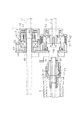
14 to 15 show a third embodiment. This embodiment includes an intermediate clutch 71 different from the
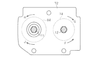
図14に示す中間クラッチ71は、ケース72に駆動ギヤ73が回転可能に支持され、その駆動ギヤ73の一側にワンウェイクラッチ74が収容されている。前記ワンウェイクラッチ74の中心部にワンウェイクラッチシャフト75が挿通され、そのワンウェイクラッチシャフト75の中心部に六角孔76が形成されている。そして、その六角孔76に前記第二の駆動軸12が挿通されている。
In an intermediate clutch 71 shown in FIG. 14, a
前記ワンウェイクラッチ74は、図15に示す矢印F方向、すなわち第二の駆動軸12のボトムレール下降方向の回転を駆動ギヤ73に伝達せず、図15に示す矢印G方向、すなわち第二の駆動軸12のボトムレール上昇方向の回転は駆動ギヤ73に伝達する。
The one-way clutch 74 does not transmit the rotation of the
前記駆動ギヤ73の側方において、前記ケース72には第一のバネクラッチシャフト77が回転可能に支持され、その第一のバネクラッチシャフト77に前記駆動ギヤ73に噛み合う被動ギヤ78が回転可能に支持されている。
On the side of the
前記被動ギヤ78の基端側の軸部79と、前記第一のバネクラッチシャフト77の基端部80とはほぼ同一径で形成され、その軸部79と基端部80の外周面にはクラッチバネ81が嵌着されている。前記第一のバネクラッチシャフト77は金属で形成され、基端部80の外径は合成樹脂で形成された前記被動ギヤ78の軸部79の外径より僅かに小さく形成されて、クラッチバネ81と第一のバネクラッチシャフト77の基端部80との間の摩擦は、クラッチバネ81と被動ギヤ78の軸部79との摩擦より小さくなるように設定されている。
A
そして、第一のバネクラッチシャフト77に中間レール3の荷重が作用している状態では、被動ギヤ78が回転されてもクラッチバネ81が第一のバネクラッチシャフト77に対し空回りして、被動ギヤ78の回転が第一のバネクラッチシャフト77に伝達されないようになっている。
In a state where the load of the
一方、第一のバネクラッチシャフト77に中間レール3の荷重が作用していない状態では、第一のバネクラッチシャフト77の基端部80とクラッチバネ81との摩擦により、被動ギヤ78の回転がクラッチバネ81を介して第一のバネクラッチシャフト77に伝達されるようになっている。
On the other hand, in a state where the load of the
前記第一のバネクラッチシャフト77の基端側において、前記ケース72に設けられた支持筒82とその周囲に位置するハウジング83との間にはワンウェイクラッチ84が配設されている。ワンウェイクラッチ84は前記支持筒82を支点として動作して、前記ハウジング83の図15に示す矢印H方向、すなわち中間レール3の引き上げ方向の回転を許容し、矢印J方向すなわち中間レール3の下降方向の回転を阻止する。
On the proximal end side of the first spring
前記ハウジング83と前記第一のバネクラッチシャフト77の基端部に延びる係合片85との間に第二のバネクラッチシャフト86が回転可能に支持され、その第二のバネクラッチシャフト86の中心部には六角孔87が形成されている。そして、その六角孔87に前記第一の駆動軸11が相対回転不能に挿通されている。また、第一の駆動軸11は、前記第一のバネクラッチシャフト77及び前記支持筒82に相対回転可能に挿通されている。
A second spring
前記第二のバネクラッチシャフト86の外周面にはクラッチバネ88が嵌着され、そのクラッチバネ88の両端は前記第一のバネクラッチシャフト77の係合片85及び前記ハウジングに係合可能となっている。また、第一のバネクラッチシャフト77が回転してその係合片85がクラッチバネ88の端部に当接するまでには所定の空転角が確保されている(空転手段)。
A
また、前記クラッチバネ88と第二のバネクラッチシャフト86との摩擦は、前記クラッチバネ81と第一のバネクラッチシャフト77との摩擦より小さくなるように設定されている。
The friction between the
この実施形態では、ストッパー装置24に収容されるドラムのうち、第二の駆動軸12が挿通される第二のドラムのガイド溝の構成が前記第一及び第二の実施形態と異なっている。
In this embodiment, the configuration of the guide groove of the second drum through which the
図16に第二のドラム28のガイド溝89を示す。このガイド溝89は、クラッチボール30を係止部34で係止してボトムレール5の自重降下を阻止している状態から、自重降下動作を解除するために第二の駆動軸12をボトムレール5の引き上げ方向(図16において矢印D方向)に回動させるとき、第二の駆動軸12の回動角を規制する係止部(制限手段)34aが形成されている。その他の構成は、前記実施形態のガイド溝31と同様である。
FIG. 16 shows the
そして、クラッチボール30が係止部34に位置してボトムレール5の自重降下が阻止されている状態から、ボールチェーン16を操作して、第二の駆動軸12をボトムレール5の引き上げ方向に回動してクラッチボール30を係止部34aまで移動させ、この状態でボールチェーン16を手放す。
Then, from the state where the
すると、クラッチボール30が下降溝32a,32bのいずれかを移動して、ボトムレール5が自重降下する。
前記第二のドラム28でクラッチボール30を前記係止部34から係止部34aまで移動させるために必要とする第二の駆動軸12の回転角は、次のように設定される。すなわち、前記第一のバネクラッチシャフト77が前記クラッチバネ88の端部に当接するまでの空転角と、前記第一のドラム27でクラッチボール30を係止部34から下降溝32a,32bのいずれかに案内するために要する角度との和より小さくなるように設定されている。
Then, the
The rotation angle of the
次に、上記のように構成された中間クラッチ71を備えたプリーツスクリーンの動作を説明する。
中間レール3及びボトムレール5を独立して昇降操作するとき、第一のバネクラッチシャフト77には第一の駆動軸11と第二のバネクラッチシャフト86とクラッチバネ88を介して中間レール3の荷重が作用している。
Next, the operation of the pleated screen provided with the intermediate clutch 71 configured as described above will be described.
When the
この状態で、ボールチェーン16を操作して、第一の駆動軸11を中間レール3の引き上げ方向に回転させると、中間クラッチ71では第一の駆動軸11の回転が第二のバネクラッチシャフト86からクラッチバネ88、第一のバネクラッチシャフト77及びクラッチバネ81を介して被動ギヤ78に伝達され、駆動ギヤ73が回転される。しかし、ワンウェイクラッチ74が空転して、駆動ギヤ73の回転は第二の駆動軸12に伝達されない。この結果、中間レール3が引き上げられ、ボールチェーン16を手放すとストッパー装置24の動作により中間レール3が所望高さに保持される。
In this state, when the
この状態から、ボールチェーン16を操作して第一の駆動軸11に対するストッパー装置24の動作を解除すると、第一の駆動軸11には中間レール3の荷重が作用する。ワンウェイクラッチ84は、ハウジング83の中間レール3下降方向の回転を阻止しているため、中間レール3の荷重により第二のバネクラッチシャフト86とクラッチバネ88との間にすべりが生じ、第一の駆動軸11及び第二のバネクラッチシャフト86が回転する。この結果、中間レール3が自重降下する。
From this state, when the operation of the
ボールチェーン16を操作して、第二の駆動軸12をボトムレール5の引き上げ方向に回転すると、中間クラッチ71ではワンウェイクラッチ74を介して駆動ギヤ73が回転され、被動ギヤ78が回転される。
When the
第一のバネクラッチシャフト77には中間レール3の荷重が作用しているので、被動ギヤ78の回転は第一のバネクラッチシャフト77に伝達されない。従って、中間レール3は引き上げられない。
Since the load of the
ストッパー装置24の動作により、ボトムレール5を所望高さで保持している状態から、ボールチェーン16の操作によりストッパー装置24の第二の駆動軸12に対する自重降下防止動作を解除すると、ボトムレール5の荷重により第二の駆動軸12が回転されてボトムレール5が自重降下する。
When the operation of the
このとき、中間クラッチ71ではワンウェイクラッチ74により第二の駆動軸12が自在に回転可能であり、駆動ギヤ73は回転されない。
ストッパー装置24により中間レール3の自重降下が阻止されている状態から、ボトムレール5で中間レール3を押し上げて、ボトムレール5及び中間レール3を一括して引き上げるとき、第二の駆動軸12の回転は駆動ギヤ73を介して被動ギヤ78に伝達される。
At this time, in the intermediate clutch 71, the
When the
被動ギヤ78の回転に基づいてクラッチバネ81が被動ギヤ78と一体に回転される。そして、第一のバネクラッチシャフト77には中間レール3の荷重が作用していないので、被動ギヤ78と第一のバネクラッチシャフト77がクラッチバネ81を介して一体に回転され、第二のバネクラッチシャフト86が第一のバネクラッチシャフト77と一体に回転される。
Based on the rotation of the driven
この結果、第一の駆動軸11が中間レール3の引き上げ方向に回転されて、第一の昇降コード6が第一の巻取軸9に巻き取られる。
ボトムレール5及び中間レール3を所望高さまで一括して引き上げた後、ボールチェーン16を手放すと、ストッパー装置24によりボトムレール5の自重降下が阻止され、ボトムレール5及び中間レール3が所望高さに保持される。
As a result, the
When the
この状態から、ボールチェーン16を操作して、第二の駆動軸12をボトムレール5の引き上げ方向に操作して、図16に示すように、第二のドラム28においてクラッチボール30を係止部34から係止部34aに移動させ、ボールチェーン16を手放すと、ボトムレール5が自重降下する。
From this state, the
このとき、第一のドラム27ではクラッチボール30が下降溝32a,32bのいずれにも達せず、ボールチェーン16を手放すことによりクラッチボール30が係止部34に復帰するので、ボトムレール5と中間レール3の同時自重降下が阻止される。
At this time, in the
上記のような中間クラッチ71及びストッパー装置24を備えたプリーツスクリーンでは、第一の実施形態で得られた作用効果に加えて、次に示す作用効果を得ることができる。
(1)ボトムレール5を引き上げて、ボトムレール5と中間レール3を一括して引き上げるとき、第一の巻取軸9で第一の昇降コード6を巻き取ることができる。従って、第一の昇降コード6のヘッドボックス1内外での弛みの発生を防止して、第一の昇降コード6のヘッドボックス1内での引っ掛かりや、畳み込まれた上部スクリーン2からのはみ出し等を未然に防止することができる。
(2)ボトムレール5及び中間レール3を一括して引き上げた後にボトムレール5を自重降下させるとき、中間レール3の同時自重降下を防止することができる。
(3)ボトムレール5と中間レール3が同時に引き上げられるとき、中間レール3の引き上げが阻止された状態でボトムレール5を無理に引き上げようとしても、第一のバネクラッチシャフト77に対し被動ギヤ78が空回りするので、中間クラッチ71の破損を未然に防止することができる。
(第四の実施形態)
図17は、第四の実施形態を示す。この実施形態は、第二の実施形態の中間クラッチ41とは異なる中間クラッチ91を備え、ストッパー装置24の構成を一部変更したものであり、その他の構成は第一及び第二の実施形態と同様である。第一及び第二の実施形態と同一構成部分は同一符号を付して詳細な説明を省略する。
In the pleated screen including the
(1) When the
(2) When the
(3) When the
(Fourth embodiment)
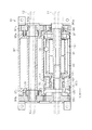
FIG. 17 shows a fourth embodiment. This embodiment includes an intermediate clutch 91 different from the
図17に示す中間クラッチ91は、ケース92の両側にクラッチドラム93a,93bが回転可能に支持され、そのクラッチドラム93a,93bの先端部に駆動ギヤ94a,94bが回転可能に支持されている。
In the intermediate clutch 91 shown in FIG. 17,
前記クラッチドラム93a,93bの外周面には、捩じりコイルスプリングで構成されるクラッチバネ95a,95bが嵌着され、そのクラッチバネ95a,95bの一端は前記駆動ギヤ94a,94bに係合している。
Clutch springs 95a and 95b composed of torsion coil springs are fitted on the outer peripheral surfaces of the
前記クラッチドラム93a,93bには前記第二の駆動軸12が相対回転不能に嵌挿されている。従って、前記クラッチドラム93a,93bは第二の駆動軸12と一体に回転される。
The
また、前記クラッチバネ95a,95bは、第二の駆動軸12がボトムレール5の引き上げ方向に回転されたとき、その回転を前記駆動ギヤ94a,94bに伝達し、第二の駆動軸12がボトムレール5の下降方向に回転されると、クラッチドラム93a,93bに対し空回りする。
The clutch springs 95a and 95b transmit the rotation to the drive gears 94a and 94b when the
前記駆動ギヤ94aに噛み合う被動ギヤ96aは、中間レール3のストッパー装置104を構成するストッパーケース97の一端部に回転可能に支持され、そのストッパーケース97の端部には一端が前記被動ギヤ96aに係合するクラッチバネ98が嵌着されている。前記ストッパーケース97は、この中間クラッチ91のケース92に対し90度の範囲で回動可能に支持されている。
The driven
前記ストッパーケース97内には前記第一の実施形態のストッパー装置24の第一のドラム27と同様なガイド溝31が形成されたドラム99が収容され、そのドラム99とストッパーケース97の内周面との間に前記ガイド溝31に沿って移動するクラッチボール30が配設されている。前記ドラム99には前記第一の駆動軸11が挿通され、ドラム99は第一の駆動軸11と一体に回転する。
The
前記ストッパーケース97の他端部に形成された筒部100内には、カム軸101が回転可能に支持され、そのカム軸101の中心部に形成された六角孔には前記第一の駆動軸11が嵌挿されて、カム軸101が第一の駆動軸11と一体に回転するようになっている。
A
前記筒部100には、前記第二の実施形態のカム筒58に形成されたガイド孔59と同様に、斜め方向のガイド孔102が形成されている。前記カム軸101の基端部には、前記ガイド孔102内に突出する突起103が形成されている。そして、ストッパーケース97が回動されると、突起103がガイド孔102沿って案内されて、カム軸101が回動しながら矢印K方向に移動するようになっている。
In the
前記駆動ギヤ94bに噛み合う被動ギヤ96bは、前記ケース92に回転可能に支持されている。そして、前記カム軸101が矢印K方向に移動したとき、カム軸101の係止片105が被動ギヤ96bに係合して、被動ギヤ96bとカム軸101が一体に回転されるようになっている。
A driven
前記第二の駆動軸12は、中間クラッチ91の外部で前記第一の実施形態のストッパー装置24の第二のドラム28と同様な自重降下防止機能を備えたドラムに挿通される。また、第一の駆動軸11はドラム99で自重降下防止機能を備えているので、別のストッパー装置を必要としない。
The
次に、上記のように構成された中間クラッチ91の動作を説明する。ボールチェーン16を操作してボトムレール5の引き上げ操作を行うとき、第二の駆動軸12がボトムレール5の引き上げ方向に回転されると、クラッチドラム93a,93bを介して駆動ギヤ94a,94bが回転される。
Next, the operation of the intermediate clutch 91 configured as described above will be described. When the
駆動ギヤ94aの回転に基づいて被動ギヤ96aが回転されるが、第一の駆動軸11からドラム99及びクラッチボール30を介してストッパーケース97に中間レール3の荷重が作用しているため、クラッチバネ98がストッパーケース97に対し空回りして、ストッパーケース97は回動されない。
The driven
駆動ギヤ94bの回転は被動ギヤ96bに伝達されるが、被動ギヤ96bはカム軸101に係合していない。従って、ボトムレール5の引き上げ動作時には中間クラッチ91は何ら機能しない。
The rotation of the
ボトムレール5の下降操作時には、ボールチェーン16の操作によりストッパー装置の自重降下防止動作が解除され、第二の駆動軸12がボトムレール5の下降方向に回転される。このとき、第二の駆動軸12の回転は駆動ギヤ94a,94bに伝達されず、中間クラッチ91は何ら機能しない。
When the
中間レール3の引き上げ操作時には、第一の駆動軸11が中間レール3の引き上げ方向に回転される。すると、ドラム99が回転されてクラッチボール30がドラム99のガイド溝31に沿って移動する。そして、ボールチェーン16を手放すと、ストッパー装置104により中間レール3が所望高さに保持される。
During the lifting operation of the
ボールチェーン16の操作により、第一の駆動軸11を回転させて、ストッパー装置104の自重降下防止動作を解除すると、第一の駆動軸11が中間レール3の下降方向に回転されて、中間レール3が自重降下する。
When the
ボトムレール5で中間レール3を押し上げて、ボトムレール5及び中間レール3を一括して引き上げるとき、ストッパーケース97には中間レール3の荷重が作用しなくなる。この状態で第二の駆動軸12がボトムレール5の引き上げ方向に回転されると、駆動ギヤ94a,94bが回転されるとともに、駆動ギヤ94bに噛み合う被動ギヤ96a,96bが回転される。
When the
被動ギヤ96aが回転されると、クラッチバネ98を介してストッパーケース97が90度回動される。すると、カム軸101が矢印K方向に移動して被動ギヤ96bと一体に回転する状態となる。この結果、第二の駆動軸12の回転が第一の駆動軸11に伝達され、中間レール3の上昇にともなって第一の昇降コード6が第一の巻取軸9に巻き取られる。
When the driven
上記のような中間クラッチ91及びストッパー装置104を備えたプリーツスクリーンでは、次に示す作用効果を得ることができる。
(1)ボトムレール5を引き上げて、ボトムレール5と中間レール3を一括して引き上げるとき、第一の巻取軸9で第一の昇降コード6を巻き取ることができる。従って、第一の昇降コード6のヘッドボックス1内外での弛みの発生を防止して、第一の昇降コード6のヘッドボックス1内での引っ掛かりや、畳み込まれた上部スクリーン2からのはみ出し等を未然に防止することができる。
In the pleated screen including the
(1) When the
上記実施形態は、以下の態様で実施してもよい。
・プリーツスクリーン、横型ブラインド、たくし上げカーテン等で、スクリーン、スラット、カーテン等を昇降する昇降装置以外にも、スクリーンの昇降により空気の流通及び遮断、断熱性を制御する装置、あるいは映写用スクリーン、防虫用スクリーン等の昇降装置に利用してもよい。
You may implement the said embodiment in the following aspects.
・ In addition to the lifting device that lifts and lowers the screen, slats, curtains, etc. with pleated screens, horizontal blinds, curtains, etc. You may utilize for lifting devices, such as an insect screen.
1…ヘッドボックス、2…遮蔽材(上部スクリーン)、3…中間レール、4…遮蔽材(下部スクリーン)、5…ボトムレール、6…第一の昇降コード、7…第二の昇降コード、13…選択操作手段(操作装置)、16…操作コード(ボールチェーン)。
DESCRIPTION OF
Claims (8)
前記昇降装置は、
前記ヘッドボックスから垂下される無端状の操作コードと、
前記操作コードの一方への操作により前記中間レールを昇降可能とし、他方への操作により前記ボトムレールを昇降可能とした選択操作手段と
を備え、
前記選択操作手段は、前記ボトムレールで前記中間レールを押し上げて、該ボトムレールと中間レールとを一括して引き上げ可能としたことを特徴とする遮蔽装置。 A first elevating cord that suspends and supports the intermediate rail and the bottom rail from the head box so that the intermediate rail and the bottom rail can be moved up and down, supports the shielding material between the intermediate rail and the bottom rail, The second elevating cord for hanging and supporting the bottom rail can be wound or unwound in the head box and the intermediate rail and the bottom rail can be raised and lowered to draw out or fold the shielding material in the vertical direction. In the shielding device provided with the lifting device
The lifting device is
An endless operation cord hanging from the head box;
A selection operation means that enables the intermediate rail to be raised and lowered by an operation to one of the operation codes, and the bottom rail to be raised and lowered by an operation to the other;
The shielding device characterized in that the selection operation means can push up the intermediate rail with the bottom rail and pull up the bottom rail and the intermediate rail together.
前記ボトムレールと中間レールを一括して引き上げるとき、前記中間レールを吊下支持する第一の昇降コードを、前記ヘッドボックス内の第一の巻取軸に巻き取る中間クラッチを備えたことを特徴とする請求項1記載の遮蔽装置。 The lifting device is
When pulling up the bottom rail and the intermediate rail at a time, an intermediate clutch is provided that winds up a first lifting / lowering cord that supports the suspension of the intermediate rail around a first winding shaft in the head box. The shielding device according to claim 1.
前記第一の昇降コードを巻き取る第一の巻取軸と、
前記ボトムレールを吊下支持する第二の昇降コードを巻き取る第二の巻取軸と、
前記第一の巻取軸を回転駆動する第一の駆動軸と、
前記第二の巻取軸を回転駆動する第二の駆動軸と
を備え、
前記中間クラッチは、
前記第一の巻取軸に前記中間レールの荷重が作用しないとき、前記第二の駆動軸の回転を前記第一の駆動軸に伝達する伝達装置を備えたことを特徴とする請求項2記載の遮蔽装置。 The lifting device is
A first winding shaft for winding the first lifting cord;
A second winding shaft that winds up a second lifting cord that supports the bottom rail in a suspended manner;
A first drive shaft for rotationally driving the first winding shaft;
A second drive shaft that rotationally drives the second winding shaft,
The intermediate clutch is
The transmission device for transmitting rotation of the second drive shaft to the first drive shaft when a load of the intermediate rail does not act on the first winding shaft. Shielding device.
前記第二の駆動軸と一体に回転する駆動ギヤと、
前記駆動ギヤに噛み合う被動ギヤと、
前記第一の巻取軸に荷重が作用しないとき、前記被動ギヤと前記第一の駆動軸を連結するカム機構と
を備えたことを特徴とする請求項3記載の遮蔽装置。 The transmission device is
A drive gear that rotates integrally with the second drive shaft;
A driven gear meshing with the drive gear;
4. The shielding apparatus according to claim 3, further comprising a cam mechanism that connects the driven gear and the first drive shaft when no load is applied to the first winding shaft.
前記第二の駆動軸のボトムレール引き上げ方向の回転のみを前記駆動ギヤに伝達するワンウェイクラッチと、
前記ワンウェイクラッチと前記第二の駆動軸との間に介在され、前記第二の駆動軸から前記ワンウェイクラッチに伝達される回転トルクを制限する伝達トルク制限装置と
を備えたことを特徴とする請求項4又は5記載の遮蔽装置。 The intermediate clutch includes
A one-way clutch that transmits only the rotation of the second drive shaft in the direction of raising the bottom rail to the drive gear;
And a transmission torque limiting device that is interposed between the one-way clutch and the second drive shaft and limits rotational torque transmitted from the second drive shaft to the one-way clutch. Item 6. The shielding device according to Item 4 or 5.
前記中間レール及びボトムレールの引き上げ操作後に前記操作コードを手放したとき、前記中間レール及びボトムレールの自重降下防止動作に移行するストッパー装置と、
前記中間レール及びボトムレールの一括引き上げ操作後に前記ストッパー装置によるボトムレールの自重降下防止動作を解除したとき、前記中間レールの自重降下防止動作の同時解除を阻止する自重降下制限装置と
を備えたことを特徴とする請求項5又は6記載の遮蔽装置。 The lifting device is
A stopper device that shifts to a self-weight drop prevention operation of the intermediate rail and the bottom rail when the operation cord is released after the lifting operation of the intermediate rail and the bottom rail;
A self-weight drop limiting device that prevents simultaneous release of the self-weight drop prevention operation of the intermediate rail when the bottom-rail weight drop prevention operation by the stopper device is canceled after the intermediate rail and the bottom rail are collectively lifted; The shielding device according to claim 5 or 6.
前記第一及び第二の駆動軸を前記中間レール及びボトムレールの引き上げ方向に回転させたとき、自重降下防止動作を解除可能とし、
前記自重降下制限装置は、
前記ボトムレールの自重降下防止動作の解除時の前記第二の駆動軸の回転角を制限する制限手段と、
前記第二の駆動軸が回転された後に前記第一の駆動軸を回転させる空転手段と
を備えたことを特徴とする請求項7記載の遮蔽装置。 The stopper device is
When the first and second drive shafts are rotated in the pulling direction of the intermediate rail and the bottom rail, the self-weight drop prevention operation can be released,
The dead weight limiting device is
Limiting means for limiting the rotation angle of the second drive shaft when the bottom rail self-weight drop prevention operation is released;
The shielding apparatus according to claim 7, further comprising an idling unit that rotates the first drive shaft after the second drive shaft is rotated.
Priority Applications (11)
| Application Number | Priority Date | Filing Date | Title |
|---|---|---|---|
| JP2009252349A JP5421069B2 (en) | 2009-11-02 | 2009-11-02 | Shielding device |
| PCT/JP2010/069444 WO2011052772A1 (en) | 2009-11-02 | 2010-11-01 | Shielding device and clutch used therefor |
| AU2010312381A AU2010312381B2 (en) | 2009-11-02 | 2010-11-01 | Shielding device and clutch used therefor |
| CN201080048014.0A CN102597408B (en) | 2009-11-02 | 2010-11-01 | Shielding device and clutch used therefor |
| KR1020127013303A KR101397680B1 (en) | 2009-11-02 | 2010-11-01 | Shielding device and clutch used therefor |
| US13/505,338 US8720523B2 (en) | 2009-11-02 | 2010-11-01 | Shielding apparatus and clutch used for the same |
| MYPI2012001928A MY159906A (en) | 2009-11-02 | 2010-11-01 | Shielding apparatus and clutch used for the same |
| BR112012010304A BR112012010304A2 (en) | 2009-11-02 | 2010-11-01 | PROTECTION DEVICE AND INTERMEDIATE CLUTCH |
| EP10826902.8A EP2497891B1 (en) | 2009-11-02 | 2010-11-01 | Shielding device and clutch used therefor |
| TW099137595A TWI509146B (en) | 2009-11-02 | 2010-11-02 | A shielding device and a clutch for a shielding device |
| HK12109278.0A HK1168403A1 (en) | 2009-11-02 | 2012-09-20 | Shielding device and clutch used therefor |
Applications Claiming Priority (1)
| Application Number | Priority Date | Filing Date | Title |
|---|---|---|---|
| JP2009252349A JP5421069B2 (en) | 2009-11-02 | 2009-11-02 | Shielding device |
Related Child Applications (1)
| Application Number | Title | Priority Date | Filing Date |
|---|---|---|---|
| JP2013239826A Division JP5650832B2 (en) | 2013-11-20 | 2013-11-20 | Shielding device |
Publications (2)
| Publication Number | Publication Date |
|---|---|
| JP2011094457A JP2011094457A (en) | 2011-05-12 |
| JP5421069B2 true JP5421069B2 (en) | 2014-02-19 |
Family
ID=44111663
Family Applications (1)
| Application Number | Title | Priority Date | Filing Date |
|---|---|---|---|
| JP2009252349A Active JP5421069B2 (en) | 2009-11-02 | 2009-11-02 | Shielding device |
Country Status (1)
| Country | Link |
|---|---|
| JP (1) | JP5421069B2 (en) |
Families Citing this family (3)
| Publication number | Priority date | Publication date | Assignee | Title |
|---|---|---|---|---|
| JP5718130B2 (en) * | 2011-04-05 | 2015-05-13 | トーソー株式会社 | Twin type solar shading device |
| JP5859801B2 (en) * | 2011-10-19 | 2016-02-16 | 立川ブラインド工業株式会社 | Solar shading device |
| JP6235231B2 (en) * | 2013-04-25 | 2017-11-22 | 立川ブラインド工業株式会社 | Solar shading material lifting device |
Family Cites Families (3)
| Publication number | Priority date | Publication date | Assignee | Title |
|---|---|---|---|---|
| JP4423979B2 (en) * | 2004-01-26 | 2010-03-03 | トーソー株式会社 | Twin type solar shading device |
| JP4982172B2 (en) * | 2006-12-27 | 2012-07-25 | 立川ブラインド工業株式会社 | Shielding material lifting device for solar radiation shielding device |
| JP5075501B2 (en) * | 2007-06-25 | 2012-11-21 | 立川ブラインド工業株式会社 | Shielding material elevating method and shielding material elevating device for solar radiation shielding device |
-
2009
- 2009-11-02 JP JP2009252349A patent/JP5421069B2/en active Active
Also Published As
| Publication number | Publication date |
|---|---|
| JP2011094457A (en) | 2011-05-12 |
Similar Documents
| Publication | Publication Date | Title |
|---|---|---|
| WO2011052772A1 (en) | Shielding device and clutch used therefor | |
| JP6346352B2 (en) | Operation device for solar shading device | |
| JP4982172B2 (en) | Shielding material lifting device for solar radiation shielding device | |
| JP5075501B2 (en) | Shielding material elevating method and shielding material elevating device for solar radiation shielding device | |
| JP5417124B2 (en) | Shielding device | |
| CN110685585B (en) | Clutch module and winch device suitable for same | |
| JP6077514B2 (en) | Shielding device | |
| JP5650832B2 (en) | Shielding device | |
| JP5421069B2 (en) | Shielding device | |
| JP5859801B2 (en) | Solar shading device | |
| JP6313486B2 (en) | Shielding device | |
| JP2012219458A (en) | Twin type solar shading device | |
| JP5376708B2 (en) | Operation device for solar shading device | |
| JP4119692B2 (en) | Solar shading material lifting device | |
| JP5315009B2 (en) | blind | |
| JP5214640B2 (en) | Solar shading material lifting device | |
| JP4516812B2 (en) | Horizontal blind slat driving device and solar shading device lifting device | |
| JP4729274B2 (en) | Shielding material lifting device for solar radiation shielding device |
Legal Events
| Date | Code | Title | Description |
|---|---|---|---|
| A621 | Written request for application examination |
Free format text: JAPANESE INTERMEDIATE CODE: A621 Effective date: 20121023 |
|
| TRDD | Decision of grant or rejection written | ||
| A01 | Written decision to grant a patent or to grant a registration (utility model) |
Free format text: JAPANESE INTERMEDIATE CODE: A01 Effective date: 20131022 |
|
| A61 | First payment of annual fees (during grant procedure) |
Free format text: JAPANESE INTERMEDIATE CODE: A61 Effective date: 20131121 |
|
| R150 | Certificate of patent or registration of utility model |
Ref document number: 5421069 Country of ref document: JP Free format text: JAPANESE INTERMEDIATE CODE: R150 |
|
| R250 | Receipt of annual fees |
Free format text: JAPANESE INTERMEDIATE CODE: R250 |
|
| R250 | Receipt of annual fees |
Free format text: JAPANESE INTERMEDIATE CODE: R250 |
|
| R250 | Receipt of annual fees |
Free format text: JAPANESE INTERMEDIATE CODE: R250 |
|
| R250 | Receipt of annual fees |
Free format text: JAPANESE INTERMEDIATE CODE: R250 |
|
| R250 | Receipt of annual fees |
Free format text: JAPANESE INTERMEDIATE CODE: R250 |
|
| R250 | Receipt of annual fees |
Free format text: JAPANESE INTERMEDIATE CODE: R250 |
|
| R250 | Receipt of annual fees |
Free format text: JAPANESE INTERMEDIATE CODE: R250 |
|
| R250 | Receipt of annual fees |
Free format text: JAPANESE INTERMEDIATE CODE: R250 |