JP5416704B2 - Solar energy collector - Google Patents
Solar energy collector Download PDFInfo
- Publication number
- JP5416704B2 JP5416704B2 JP2010530961A JP2010530961A JP5416704B2 JP 5416704 B2 JP5416704 B2 JP 5416704B2 JP 2010530961 A JP2010530961 A JP 2010530961A JP 2010530961 A JP2010530961 A JP 2010530961A JP 5416704 B2 JP5416704 B2 JP 5416704B2
- Authority
- JP
- Japan
- Prior art keywords
- reflector
- heat
- light energy
- reflector unit
- support
- Prior art date
- Legal status (The legal status is an assumption and is not a legal conclusion. Google has not performed a legal analysis and makes no representation as to the accuracy of the status listed.)
- Expired - Fee Related
Links
Images


Classifications
-
- F—MECHANICAL ENGINEERING; LIGHTING; HEATING; WEAPONS; BLASTING
- F24—HEATING; RANGES; VENTILATING
- F24S—SOLAR HEAT COLLECTORS; SOLAR HEAT SYSTEMS
- F24S23/00—Arrangements for concentrating solar-rays for solar heat collectors
- F24S23/70—Arrangements for concentrating solar-rays for solar heat collectors with reflectors
- F24S23/81—Arrangements for concentrating solar-rays for solar heat collectors with reflectors flexible
-
- F—MECHANICAL ENGINEERING; LIGHTING; HEATING; WEAPONS; BLASTING
- F24—HEATING; RANGES; VENTILATING
- F24S—SOLAR HEAT COLLECTORS; SOLAR HEAT SYSTEMS
- F24S23/00—Arrangements for concentrating solar-rays for solar heat collectors
- F24S23/70—Arrangements for concentrating solar-rays for solar heat collectors with reflectors
- F24S23/74—Arrangements for concentrating solar-rays for solar heat collectors with reflectors with trough-shaped or cylindro-parabolic reflective surfaces
- F24S23/745—Arrangements for concentrating solar-rays for solar heat collectors with reflectors with trough-shaped or cylindro-parabolic reflective surfaces flexible
-
- F—MECHANICAL ENGINEERING; LIGHTING; HEATING; WEAPONS; BLASTING
- F24—HEATING; RANGES; VENTILATING
- F24S—SOLAR HEAT COLLECTORS; SOLAR HEAT SYSTEMS
- F24S23/00—Arrangements for concentrating solar-rays for solar heat collectors
- F24S23/70—Arrangements for concentrating solar-rays for solar heat collectors with reflectors
- F24S23/80—Arrangements for concentrating solar-rays for solar heat collectors with reflectors having discontinuous faces
-
- F—MECHANICAL ENGINEERING; LIGHTING; HEATING; WEAPONS; BLASTING
- F24—HEATING; RANGES; VENTILATING
- F24S—SOLAR HEAT COLLECTORS; SOLAR HEAT SYSTEMS
- F24S40/00—Safety or protection arrangements of solar heat collectors; Preventing malfunction of solar heat collectors
- F24S40/80—Accommodating differential expansion of solar collector elements
-
- F—MECHANICAL ENGINEERING; LIGHTING; HEATING; WEAPONS; BLASTING
- F24—HEATING; RANGES; VENTILATING
- F24S—SOLAR HEAT COLLECTORS; SOLAR HEAT SYSTEMS
- F24S80/00—Details, accessories or component parts of solar heat collectors not provided for in groups F24S10/00-F24S70/00
- F24S80/40—Casings
-
- F—MECHANICAL ENGINEERING; LIGHTING; HEATING; WEAPONS; BLASTING
- F24—HEATING; RANGES; VENTILATING
- F24S—SOLAR HEAT COLLECTORS; SOLAR HEAT SYSTEMS
- F24S23/00—Arrangements for concentrating solar-rays for solar heat collectors
- F24S23/70—Arrangements for concentrating solar-rays for solar heat collectors with reflectors
- F24S2023/83—Other shapes
- F24S2023/834—Other shapes trough-shaped
- F24S2023/835—Other shapes trough-shaped asymmetric
-
- F—MECHANICAL ENGINEERING; LIGHTING; HEATING; WEAPONS; BLASTING
- F24—HEATING; RANGES; VENTILATING
- F24S—SOLAR HEAT COLLECTORS; SOLAR HEAT SYSTEMS
- F24S80/00—Details, accessories or component parts of solar heat collectors not provided for in groups F24S10/00-F24S70/00
- F24S2080/01—Selection of particular materials
- F24S2080/015—Plastics
-
- Y—GENERAL TAGGING OF NEW TECHNOLOGICAL DEVELOPMENTS; GENERAL TAGGING OF CROSS-SECTIONAL TECHNOLOGIES SPANNING OVER SEVERAL SECTIONS OF THE IPC; TECHNICAL SUBJECTS COVERED BY FORMER USPC CROSS-REFERENCE ART COLLECTIONS [XRACs] AND DIGESTS
- Y02—TECHNOLOGIES OR APPLICATIONS FOR MITIGATION OR ADAPTATION AGAINST CLIMATE CHANGE
- Y02E—REDUCTION OF GREENHOUSE GAS [GHG] EMISSIONS, RELATED TO ENERGY GENERATION, TRANSMISSION OR DISTRIBUTION
- Y02E10/00—Energy generation through renewable energy sources
- Y02E10/40—Solar thermal energy, e.g. solar towers
Description
この発明は、一般に、いわゆる太陽エネルギー集光器と呼ばれる装置に関する。より具体的には、本発明は、太陽光線によりもたらされる熱及び/又は光エネルギーの一部を利用することのできる、行と列の形でマニホールド内に配設される装置及びユニットを意図するものである。
したがって、さらに詳細には、この発明は、太陽光線に向けることが可能な、太陽光線を反射する反射体ユニットと、この反射体ユニットに関連する、熱及び/又は光エネルギーを吸収する手段とを有し、照射された太陽光線から生じる主として熱エネルギーを吸収するよう適合された装置を提供することを可能とすることを意図する。
そのような反射体ユニット及び熱吸収手段は、太陽光線や光に対して透明な保護体で被覆可能であり、反射体ユニット及び熱吸収手段は、薄くて容易に屈曲可能な材質から形成されるとともに、高い反射率のものに予め形成した、光を反射する反射体表面を具えることが有利である。
The present invention generally relates to an apparatus called a so-called solar energy collector. More specifically, the present invention contemplates devices and units arranged in a manifold in rows and columns that can utilize a portion of the heat and / or light energy provided by solar radiation. Is.
Thus, more particularly, the present invention comprises a reflector unit that reflects sunlight, which can be directed to the sunlight, and means for absorbing heat and / or light energy associated with the reflector unit. It is intended to make it possible to provide a device that is adapted and adapted to absorb mainly thermal energy arising from irradiated solar radiation.
Such a reflector unit and heat absorbing means can be covered with a protective body transparent to sunlight and light, and the reflector unit and heat absorbing means are made of a thin and easily bendable material. At the same time, it is advantageous to have a reflector surface that reflects light and is pre-formed with high reflectivity.
従来より、上記の技術分野に関連する方法、装置及び設計は、複数の異なる実施の態様で知られている。
このことに関し、数学的計算により入射した太陽光線を焦点に集中させ、熱集中を増大できるような、曲面形状の反射体表面を作ることができることが解明されている。
そして、長手方向もしくは縦方向への延在長さを有する太陽電池及び/又は太陽エネルギー集光器では、焦点が、水/グリコール混合物等の、細長い媒体内に熱を吸収するための焦点セグメントもしくはラインを形成可能であることが知られている。
Conventionally, methods, apparatus and designs related to the above technical fields are known in a number of different embodiments.
In this regard, it has been elucidated that a curved reflector surface capable of concentrating the incident sunlight rays on the focal point and increasing the heat concentration can be made by mathematical calculation.
And in solar cells and / or solar energy concentrators that have a longitudinal or longitudinal extension, the focal point is a focal segment for absorbing heat in an elongated medium, such as a water / glycol mixture or It is known that lines can be formed.
また、一方では、光線状の発生した熱エネルギーを温水の流動に変換できる可能性があり、他方では、複数の光/電気コンバータを用いることによって、光線状の発生した熱エネルギーを電気的エネルギーに変換できる可能性がある、熱吸収手段を利用するための様々な構造物もまた知られている。
光/電気コンバータは、様々な実施の態様で用いられており、この光/電気コンバータの効率性を高めることが、近年の目覚ましい開発における課題となっている。
Also, on the one hand, there is a possibility that the heat energy generated in the form of rays can be converted into the flow of hot water. Various structures are also known for utilizing heat absorption means that may be converted.
Optical / electrical converters are used in various embodiments, and increasing the efficiency of the optical / electrical converters has become a challenge in recent remarkable developments.
この技術分野では、太陽電池及び/又は太陽エネルギー集光器を、回転可能な基部に取り付け、他の電気回路装置や制御設備を用いて、常時、太陽電池もしくは太陽エネルギー集光器を、照射される太陽光線を向く方向に回転させるとともに、太陽電池及び反射表面を、照射される太陽光線に直交する方向に傾斜ないしは傾転させることも知られている。 In this technical field, solar cells and / or solar energy concentrators are attached to a rotatable base and are constantly irradiated with solar cells or solar energy concentrators using other electrical circuit devices and control equipment. It is also known that the solar cell and the reflecting surface are tilted or tilted in a direction orthogonal to the irradiated solar rays while rotating in the direction facing the solar rays.
また、この発明に関する先行技術及び技術分野のさらなる例示として、照射された太陽光線から生じる主たる熱を吸収するよう適合された装置であって、太陽光線に向けることが可能な、太陽光線を反射する反射体表面と、反射体ユニットに連結された熱及び/又は光エネルギー吸収手段とを具えるものについて言及する。
そのような装置では、前記反射体ユニットと、熱及び/又は光エネルギー吸収手段とを、太陽光線に対し透明で、かつ、機械的な動作及び/又は損傷に対する耐久性を具えた保護体で被覆し、また、前記反射体ユニット、とくに反射体表面を、薄くて容易に湾曲可能な材料から形成すべきである。
Also, as a further illustration of the prior art and technical field relating to the present invention, a device adapted to absorb the main heat arising from irradiated solar rays, which reflects the solar rays that can be directed to the solar rays Reference is made to what comprises a reflector surface and heat and / or light energy absorbing means coupled to the reflector unit.
In such an apparatus, the reflector unit and the heat and / or light energy absorbing means are covered with a protective body that is transparent to sunlight and has durability against mechanical operation and / or damage. In addition, the reflector unit, particularly the reflector surface, should be made of a thin and easily bendable material.
かかる先行技術として、太陽光集光ボックスもしくは容器をさらに具えたものが、スウェーデン国実用新案登録出願第2007/0008号に基づくスウェーデン国実用新案登録第79 604号(特許文献1)に記載されている。 As such prior art, a further provided with a solar condensing box or container is described in Swedish Utility Model Registration No. 79 604 (Patent Document 1) based on Swedish Utility Model Registration Application No. 2007/0008. Yes.
また、先行技術としては、特許文献2、特許文献3及び特許文献4に記載されたものがある。
特許文献2には、円筒パラボラ反射体が開示されており、これによれば、照射された太陽光線を、前記円筒に割り当てた焦点軸に向けて集中させることができる。
この文献の図1には、シート状金属材料からなり、一体とされた従来の反射体ユニットが示されている。
そして、この文献では、機械依存的で温度依存的な力に対抗させることを目的として、半径方向に向いた補強用手段(2)及び、垂直方向に向いた被補強手段(3)のそれぞれを設けたことにもかかわらず、そのような力の影響の下で、反射表面(1)が変形の対象となり得る。
とくに、焦点軸に連結するパイプ(4)が、半径方向に向いた補強用手段(2)に対して変位可能な態様で、支持手段(5)によって固定される点が示されている。
Further, as prior art, there are those described in Patent Document 2,
Patent Document 2 discloses a cylindrical parabolic reflector, and according to this, it is possible to concentrate the irradiated sunlight toward the focal axis assigned to the cylinder.
FIG. 1 of this document shows a conventional reflector unit made of a sheet metal material and integrated.
In this document, each of the reinforcing means (2) oriented in the radial direction and the reinforced means (3) oriented in the vertical direction is used for the purpose of countering the machine-dependent and temperature-dependent forces. Despite being provided, the reflective surface (1) can be subject to deformation under the influence of such forces.
In particular, it is shown that the pipe (4) connected to the focal axis is fixed by the support means (5) in such a manner that it can be displaced relative to the reinforcing means (2) oriented in the radial direction.
また、この特許文献2の図2では、モジュールが、他のモジュールと連携して、太陽エネルギー集光器を形成することが開示されている。
ここで、凹面は、光沢研磨、あるいは光沢加工を施した厚さ1mmのアルミニウムシートからなるものとし、装置(6)の他の5つの細部をより硬い材料で形成することが記載されている。
さらに、二個のアルミニウム製パイプ(7、7´)のそれぞれを、発泡プラスチック内に埋設するとともに、内径及び外径を18/20mmの寸法とすることが記載されている。
Moreover, in FIG. 2 of this patent document 2, it is disclosed that a module forms a solar energy collector in cooperation with other modules.
Here, it is described that the concave surface is made of an aluminum sheet having a thickness of 1 mm subjected to gloss polishing or gloss processing, and that the other five details of the device (6) are formed of a harder material.
Further, it is described that each of the two aluminum pipes (7, 7 ') is embedded in a foamed plastic, and the inner diameter and the outer diameter are 18/20 mm.
パイプ(7、7´)の端部領域(8、8´)は、パネルから25mmの距離を越えて延在するとともに、18mmの外径を有する。より狭い先端領域(8、8´)は、隣接するパネル(6a)の、同種のパイプもしくはバーの端部領域(8a、8a´)に、圧入により連結される。
アルミニウムシートは、補強のために、逆側の端部領域に沿って角張らせている。
The end region (8, 8 ') of the pipe (7, 7') extends beyond a distance of 25 mm from the panel and has an outer diameter of 18 mm. The narrower tip region (8, 8 ') is connected by press fitting to the end region (8a, 8a') of the same type of pipe or bar of the adjacent panel (6a).
The aluminum sheet is squared along the opposite end region for reinforcement.
特許文献3には、熱線の集熱ユニットが図示及び記載されている。
このユニットは、被覆部材もしくはボックス(1)を有し、その被覆部材もしくはボックス(1)は、開口上方部分と、内部に、互いに隣り合わせに配置した複数の熱反射モジュール(2)とを具えてなるものである。
各モジュール(2)は、筒状の熱吸収手段(3)及び反射体(4)を具え、手段(3)に向けて熱戦を反射させる。その手段(3)の相互は、連結パイプ(3a)によって連結される。
ボックス(1)の開口端部領域は、複数のガラス部材その他の透明な材料で閉じられ、ボックス(1)の内部の断熱性が確保されるべきである。
This unit has a covering member or box (1), and the covering member or box (1) includes an upper part of the opening and a plurality of heat reflection modules (2) arranged inside each other next to each other. It will be.
Each module (2) includes a cylindrical heat absorbing means (3) and a reflector (4), and reflects the thermal battle toward the means (3). The means (3) are connected to each other by a connecting pipe (3a).
The open end region of the box (1) should be closed with a plurality of glass members or other transparent materials to ensure the heat insulation inside the box (1).
とくに、この特許文献3では、反射体(4)をプレス板によりプレス加工する点及び、この反射体(4)に、セントラルエッジ(42b)を形成する点が教示されている。
さらには、反射体(42)を所定の幅寸法とすることにより、反射体が窪み(41a)に押し込まれた際に、両端部分が、反射体シートを、それ自身の屈曲能力に基いて選択的な所定の配置姿勢とするべく、該両端部分に対応する部分(41b)とともに機能することになる。
In particular,
Furthermore, by setting the reflector (42) to a predetermined width dimension, when the reflector is pushed into the recess (41a), both end portions select the reflector sheet based on its own bending ability. In order to obtain a specific predetermined arrangement posture, it functions together with the portions (41b) corresponding to the both end portions.
特許文献4には、薄い反射体シートと、光沢研磨、あるいは光沢加工を施した反射体表面とを具える太陽エネルギー集光器が開示されており、この装置では、前記シートを、図5に示されるような、複数の支持補強部材(18)を有する二個の細長部材(14、16)を具えた剛体構造物で支持させ、また、適切な反射体材料からなる内表面(20)が、パラボラ形状に相当する形状となるように、支持補強部分の形状を特定するものとしている。
関連のある技術分野における当業者が、一もしくはそれ以上の技術的課題に対する解決策を提示するために行うべき技術的な考察は、一方では、第一に、採用すべき手段及び/又は一連の手段についての必要な理解であり、他方では、要求される手段の必要な選択であるという状況に着目すれば、その後に生じる技術的課題は、かかる事情に鑑みて、発明の現在の主題を創出することに関連するものである。 The technical considerations to be made by a person skilled in the relevant technical field in order to present a solution to one or more technical problems, on the one hand, Focusing on the situation that it is a necessary understanding of the means, and on the other hand, the necessary choice of the required means, the subsequent technical challenges will create the current subject of the invention in view of such circumstances. It is related to doing.
従って、先に述べた従来技術を考慮し、照射された太陽光線から生じる主として熱及び/又は光エネルギーを吸収するための装置であって、太陽光線に向けることが可能な、太陽光線を反射する反射体ユニットと、該反射体ユニットに連結された熱及び/又は光エネルギー吸収手段とを具え、前記反射体ユニット及び前記吸収手段を、透明な保護体で被覆するとともに、前記反射体ユニットと、その主として反射体表面を、薄くて容易に湾曲可能な材料から形成してなり、その他の点においては、完全な構成を教示して与えることのできる、請求項1の前文で特定した特徴事項を有する装置において、それらに関連する利点及び/又は、必要とされる技術的手段及び考察の意義を実現することを技術的課題とする。 Therefore, in view of the prior art described above, it is an apparatus for mainly absorbing heat and / or light energy generated from irradiated solar rays, and reflects the solar rays that can be directed to the solar rays. A reflector unit; and heat and / or light energy absorbing means coupled to the reflector unit, the reflector unit and the absorbing means are covered with a transparent protective body, and the reflector unit; The features specified in the preamble of claim 1, wherein the reflector surface is mainly formed of a thin and easily bendable material, and can otherwise teach and provide a complete construction. It is an object of the present invention to realize the advantages associated with them and / or the significance of the necessary technical means and considerations.
また、先に述べた従来技術を考慮して、太陽電池及び太陽エネルギー集光器に必須かつ必要とされる材料の量を総合的に減らすことを目的とし、それに関連する利点及び/又は、必要とされる技術的手段及び考察の意義を実現することを技術的課題とする。 In addition, in view of the prior art described above, the aim is to reduce the total amount of materials essential and required for solar cells and solar energy concentrators, and the related advantages and / or requirements The technical problem is to realize the technical means and the significance of consideration.
先に述べた従来技術を考慮して、従来の太陽電池もしくは太陽エネルギー集光器のような、ある同一の出力での、太陽電池及び/又は太陽エネルギー集光器に要求される限定領域を教示して与えることのできることを必要とする、それに関連する利点及び/又は、必要とされる技術的手段及び考察の意義を実現することを技術的課題とするものである。 Teaching the limited areas required for solar cells and / or solar energy concentrators at one and the same output, such as conventional solar cells or solar energy concentrators, considering the prior art described above The technical problem is to realize the advantages and / or the technical means required and the significance of the considerations that need to be given.
前記反射体ユニットが、「反射体スプリング」として後述する複数の支持部材であって、前記反射体ユニットの長手方向もしくは縦方向の延在長さに沿って反射体表面にわたって分布し、その縦方向延在長さに直交、又は実質的に直交する向きで配設した支持部材と連携して、温度の影響に応じて、反射体ユニット及び反射体表面が、安定した外形形状を維持しつつ、採用された形状及び/又は材料の選択に応じて弾性域内で変形できるようにすることを目的とし、それに関連する利点及び/又は、必要とされる技術的手段及び考察の意義を実現することを技術的課題とする。 The reflector unit is a plurality of support members to be described later as “reflector springs”, and is distributed over the reflector surface along the longitudinal or longitudinal extension length of the reflector unit. In cooperation with the support member arranged in a direction orthogonal to the extension length or substantially orthogonal, the reflector unit and the reflector surface maintain a stable outer shape according to the influence of temperature, The purpose is to be able to deform within the elastic range depending on the choice of the shape and / or material adopted, and to realize the advantages and / or the technical means and considerations required therefor. Technical issue.
太陽光線を反射する表面もしくは反射体表面の同一の反射体形状を維持しつつ、温度変化の発生に起因して生じる、反射体表面及び支持台の変位を許容するために、それぞれの、もしくは選択された反射体スプリングを、細いワイヤもしくは薄いストリップとして形成するとともに、支持部材もしくは反射体スプリングを湾曲形状とすることを目的とし、それに関連する利点及び/又は、必要とされる技術的手段及び考察の意義を実現することを技術的課題とする。 Respectively or selected to allow the displacement of the reflector surface and the support base caused by the occurrence of temperature changes while maintaining the same reflector shape of the surface reflecting the reflector or the surface of the reflector The formed reflector springs are formed as thin wires or thin strips and the support member or reflector springs are of a curved shape, with the associated advantages and / or technical means and considerations required Realizing the significance of this is a technical issue.
熱及び/又は光エネルギー吸収手段に向けて太陽光線を反射することに適した、反射体表面の形状を維持するために、前記反射体スプリングを湾曲形状に曲げて、その形状を維持することを目的とし、それに関連する利点及び/又は、必要とされる技術的手段及び考察の意義を実現することを技術的課題とする。 In order to maintain the shape of the reflector surface, which is suitable for reflecting sunlight rays toward heat and / or light energy absorbing means, the reflector spring is bent into a curved shape, and the shape is maintained. The technical problem is to realize the purpose and the advantages associated therewith and / or the significance of the necessary technical means and considerations.
反射体ユニット、主として反射体表面の、縦方向への動きないしは変位が生じる温度変化の発生を補償することを目的とし、それに関連する利点及び/又は、必要とされる技術的手段及び考察の意義を実現することを技術的課題とする。 The aim is to compensate for the occurrence of temperature changes that cause longitudinal movement or displacement of the reflector unit, mainly the reflector surface, and the associated advantages and / or the significance of the necessary technical means and considerations. The technical challenge is to achieve the above.
箱型の容器である、いわゆるリブ付きボックスの利用を可能とする、ガラスその他のカバー板のような透明な保護体を支持するために、反射体ユニット及び/又は反射体表面、ならびに、支持台又は支持部分を、たとえば平行線等の直線に沿うように支持する縦方向の縁部を設けることを目的とし、それに関連する利点及び/又は、必要とされる技術的手段及び考察の意義を実現することを技術的課題とする。 Reflector unit and / or reflector surface and support base to support transparent protectors such as glass or other cover plates that allow the use of so-called ribbed boxes that are box-shaped containers Alternatively, the purpose is to provide a longitudinal edge that supports the supporting part along a straight line, for example parallel lines, and realizes the advantages and / or significance of the necessary technical means and considerations. Doing this is a technical issue.
リブ付きボックスの縦方向の縁部分に、連携可能な縦方向縁部と連携するよう適合された一以上のノッチを形成することを目的とし、それに関連する利点及び/又は、必要とされる技術的手段及び考察の意義を実現することを技術的課題とする。 The purpose and / or required technique associated with forming at least one notch adapted to cooperate with the cooperable longitudinal edge at the longitudinal edge of the ribbed box It is a technical subject to realize the significance of the technical means and consideration.
リブ付きボックスを、軽量な材料、たとえば木材及び/又は複合材料から形成することを目的とし、それに関連する利点及び/又は、必要とされる技術的手段及び考察の意義を実現することを技術的課題とする。 The technical aim is to form a ribbed box from a light-weight material, for example wood and / or composite material, and to realize the advantages and / or the technical means and the significance of the considerations involved. Let it be an issue.
前記反射体スプリングが、反射体表面に密に連結され、これを支持するとともに、前記熱及び/又は光エネルギー吸収手段の支持として連結するよう適合可能とすることを目的とし、それに関連する利点及び/又は、要とされる技術的手段及び考察の意義を実現することを技術的課題とする。 The reflector spring is closely connected to and supports the reflector surface and is intended to be adaptable to connect as a support for the heat and / or light energy absorbing means, and its associated advantages and The technical problem is to realize the technical means required and the significance of consideration.
反射体ユニット、とくに反射体表面に与える集中係数を適合範囲内で選択し、たとえば3.0〜4.0の範囲の値とすることを目的とし、それに関連する利点及び/又は、必要とされる技術的手段及び考察の意義を実現することを技術的課題とする。 The aim is to select a concentration factor to be applied to the reflector unit, in particular the reflector surface, within a suitable range, for example to a value in the range of 3.0 to 4.0, and related advantages and / or required It is a technical subject to realize the technical means and the significance of consideration.
太陽光及び太陽光線の入射を、低い至点の場合には、熱及び/又は光エネルギー吸収手段の一端に向けて集中させるとともに、高い至点の場合には、前記手段の他端に向けて集中させるべく、反射体表面を含む反射体ユニットと、熱及び/又は光エネルギー吸収手段との相互の向きを適合させることを目的とし、それに関連する利点及び/又は、必要とされる技術的手段及び考察の意義を実現することを技術的課題とする。 In the case of low solstice, the incident sunlight and sunlight are concentrated toward one end of the heat and / or light energy absorbing means, and in the case of high solstice, toward the other end of the means. The purpose and / or required technical means associated with the purpose of adapting the mutual orientation of the reflector unit, including the reflector surface, and the heat and / or light energy absorbing means to be concentrated And the technical challenge is to realize the significance of consideration.
前記リブ付きボックスを、固定基部に固定して設置することを目的とし、それに関連する利点及び/又は、に必要とされる技術的手段及び考察の意義を認識することを技術的課題とする。 The purpose of the ribbed box is to be fixedly installed on a fixed base, and the technical problem is to recognize the advantages and / or technical means required for it and the significance of consideration.
反射体表面の、反射体スプリングに沿う、断面での曲線形状を、CPC機能(複合パラボラ集光器)に対応する関数に関連付けることを目的とし、それに関連する利点及び/又は、必要とされる技術的手段及び考察の意義を実現することを技術的課題とする。 The purpose and / or required associated with the purpose of associating the curved shape of the cross section of the reflector surface along the reflector spring with a function corresponding to the CPC function (composite parabolic concentrator) Realizing the significance of technical means and consideration is a technical issue.
反射体ユニット及び/又は反射体表面の一方の長手方向縁部に隣接する位置に、熱及び/又は光エネルギー吸収装置の逆側に向く、縦方向もしくは長手方向の支持型を設けることを目的とし、それに関連する利点及び/又は、必要とされる技術的手段及び考察の意義を実現することを技術的課題とする。 The purpose is to provide a longitudinal or longitudinal support mold facing the opposite side of the heat and / or light energy absorber at a position adjacent to one longitudinal edge of the reflector unit and / or reflector surface. The technical problem is to realize the advantages and / or the significance of the necessary technical means and considerations.
前記支持型に隣接ないしは近接して配設される角部もしくは角度付き延在部分を、前記反射体スプリングのそれぞれに設けることを目的とし、それに関連する利点及び/又は、必要とされる技術的手段及び考察の意義を実現することを技術的課題とする。 It is intended to provide each of the reflector springs with a corner or an angled extension that is disposed adjacent to or in close proximity to the support mold, and its associated advantages and / or technical requirements Realizing the significance of means and consideration is a technical issue.
前記反射体表面及び、支持台及び/又は支持部分を、互いに一体的に形成することを目的とし、それに関連する利点及び/又は、必要とされる技術的手段及び考察の意義を実現することを技術的課題とする。 The reflector surface and the support base and / or the support part are intended to be integrally formed with each other, realizing the advantages and / or the significance of the necessary technical means and considerations. Technical issue.
様々な支持圧力の作用下においても、反射体スプリングを、反射体表面及び支持台に支持されるものとすることを目的とし、それに関連する利点考察及び/又は、そのために必要とされる技術的手段及びの意義を実現することを技術的課題とする。 The purpose of the reflector spring is to be supported on the reflector surface and the support base even under the action of various support pressures, and the related advantages considerations and / or technical requirements required therefor The technical challenge is to realize the means and significance.
反射体スプリングの中間部もしくは最下部が、最大圧力又は、反射体スプリングの端部に作用するものよりも大きい圧力を吸収するものとすることを目的とし、それに関連する利点及び/又は、そのために必要とされる技術的手段及び考察の意義を実現することを技術的課題とする。 It is intended that the middle or lowermost part of the reflector spring absorbs the maximum pressure or pressure that is greater than that acting on the end of the reflector spring, and its related advantages and / or for that purpose The technical challenge is to realize the necessary technical means and the significance of consideration.
前記端部に、小さな支持圧力が作用するか、あるいは、全く支持圧力が作用しないものとすることを目的とし、それに関連する利点及び/又は、必要とされる技術的手段及び考察の意義を実現することを技術的課題とする。 The purpose is to have a small support pressure or no support pressure at the end, and realize the advantages and / or the technical means and considerations required for that. Doing this is a technical issue.
この発明は、先に述べた既知の技術に基いて創出されたものであり、
受け取った太陽光線から生じる、主として熱及び/又は光エネルギーを吸収するよう適合された装置において、
太陽光線に向けることが可能な、太陽光線を反射する反射体ユニットと、その反射体ユニットに連結された熱及び/又は光エネルギー吸収手段とを具え、
前記反射体ユニット並びに、熱及び/又は光エネルギー吸収手段を、透明な保護体で被覆するとともに、前記反射体表面及び、その支持台もしくは支持部分を、薄くて容易に湾曲可能な材料から形成してなることを前提とするものである。
This invention was created based on the known technology described above,
In a device adapted to absorb mainly heat and / or light energy arising from received solar radiation,
A reflector unit capable of directing sunlight and reflecting sunlight, and heat and / or light energy absorbing means coupled to the reflector unit;
The reflector unit and the heat and / or light energy absorbing means are covered with a transparent protective body, and the reflector surface and its support base or support part are made of a thin and easily bendable material. It is assumed that
この発明はまた、前記反射体ユニット、主として反射体表面を、その反射体ユニットの長手方向もしくは縦方向の延在長さに沿って分布させた複数の支持部材との連携に適合させることをも前提とするものである。 The present invention is also adapted to adapt the reflector unit, mainly the reflector surface, to cooperation with a plurality of support members distributed along the longitudinal or longitudinal extension length of the reflector unit. It is a premise.
前記支持部材は、温度作用の影響を受ける反射体ユニット及び/又は反射体表面が、安定した外径形状を維持しつつ、採用された形状及び/又は材質の選択に応じて弾性域内で変形するように、反射体表面の下方で、縦方向の延在長さに実質的に直交する向きに設けるものである。 The support member is deformed in the elastic region according to the selection of the adopted shape and / or material while maintaining the stable outer diameter shape of the reflector unit and / or the reflector surface affected by the temperature effect. Thus, it is provided in the direction substantially orthogonal to the extending length in the vertical direction below the reflector surface.
一以上の上述した技術的課題を解決するために、この発明は、上記の既知の技術を、とくに、以下のように改良すべきであることを教示するものである。
すなわち、前記支持部材に加えて、さらなる支持部材を設け、反射体スプリングとしての形態をなす後者の支持部材を、反射体ユニットもしくは反射体表面の反射面に当接させ、
太陽光線を反射する表面としての反射体形状の同一性を維持しつつ、反射体ユニット及び/又は反射体表面の、温度変化による動きを許容するために、支持部材もしくは反射体スプリングのそれぞれを、細いワイヤもしくは薄いストリップとして形成してなるものとする。
In order to solve one or more of the above technical problems, the present invention teaches that the above known technique should be improved in particular as follows.
That is, in addition to the support member, a further support member is provided, and the latter support member in the form of a reflector spring is brought into contact with the reflector unit or the reflection surface of the reflector surface,
In order to allow movement of the reflector unit and / or the reflector surface due to temperature changes while maintaining the identity of the reflector shape as the surface that reflects sunlight, each of the support member or the reflector spring is It shall be formed as a thin wire or thin strip.
この発明の基本的な概念の範囲内に属する、提案する実施形態に示すように、この発明は、反射体表面を、熱及び/又は光エネルギー吸収手段に向けて太陽光線を反射するよう適合された最適な形状に維持するため、ここでの反射体スプリングは、反射体表面の曲面に整合するように湾曲させた形状とすることができることをさらに教示する。 As shown in the proposed embodiment, which falls within the basic concept of the present invention, the present invention is adapted to reflect sunlight toward the reflector surface towards heat and / or light energy absorbing means. Further, it is further taught that the reflector spring herein can be curved to match the curved surface of the reflector surface in order to maintain the optimum shape.
この発明は、反射体ユニット、とくに反射体表面の、温度変化により引き起こされる縦延在方向への動きを補償できることの可能性について提案するものである。 The present invention proposes the possibility of compensating for the movement of the reflector unit, particularly the reflector surface, in the longitudinal direction caused by temperature changes.
反射体ユニットもしくは反射体表面の縦方向縁部を、たとえば平行線などの直線に沿って支持するため、また、ガラスその他のカバープレートなどの透明な保護体を支持するため、先述したスウェーデン実用新案登録公報で示されるように、いわゆるリブ付きボックスと呼ばれる箱型の容器を用いることが好ましい。
そのようなリブ付きボックスの縦方向の縁部分には、温度変動に起因する相対的な変位に対して連携可能な縦方向縁部と連携するよう適合されたノッチを設けることができる。
ここで、リブ付きボックスは、木材及び/又は複合材料から形成することできる。
In order to support the longitudinal edges of the reflector unit or the reflector surface along straight lines such as parallel lines, and to support transparent protective bodies such as glass and other cover plates, the Swedish utility model mentioned above As shown in the registered publication, it is preferable to use a box-shaped container called a so-called ribbed box.
The longitudinal edge of such a ribbed box can be provided with a notch adapted to cooperate with a longitudinal edge that can cooperate with relative displacement due to temperature fluctuations.
Here, the ribbed box can be formed from wood and / or composite material.
前記反射体スプリングは、一方では、反射体表面に、有利には多様な支持圧力の作用下で、密に接続され、他方では、熱もしくは光エネルギー吸収手段を支持するように連結すべきである。 Said reflector spring should be connected on the one hand to the reflector surface, preferably under the action of various support pressures, and on the other hand to support the heat or light energy absorbing means. .
反射体ユニットに与える集中係数は、3.0〜4.0の範囲内の値を採用すべきである。 The concentration factor given to the reflector unit should be a value within the range of 3.0 to 4.0.
入射する太陽光線を、高い至点の場合には、熱及び/又は光エネルギー吸収手段の一端に向けて集中させるとともに、低い至点の場合には、前記手段の他端に向けて集中させ、あるいはこの逆とすべく、反射体表面を含む反射体ユニット並びに、熱及び/又は光エネルギー吸収手段の相互の向きを適合させることができる。 Incident solar rays are concentrated toward one end of the heat and / or light energy absorbing means in the case of a high solstice, and are concentrated toward the other end of the means in the case of a low solstice, Alternatively, the reverse may be achieved by adapting the mutual orientation of the reflector unit including the reflector surface and the heat and / or light energy absorbing means.
好ましくは、前記リブ付きボックスを、固定基部に固定して設置する。 Preferably, the box with ribs is fixedly installed on a fixed base.
反射体表面の、反射体スプリングに沿う、断面内での曲線形状は、CPCユニット(複合パラボラ集光器)に対応する関数に関連付ける。 The curved shape of the reflector surface along the reflector spring in the cross section is related to the function corresponding to the CPC unit (composite parabolic concentrator).
反射体ユニットの長手方向の縁部の一つに隣接する位置には、熱及び/又は光エネルギー吸収手段の逆側を向く長手方向の支持型を設ける。 A longitudinal support mold facing the opposite side of the heat and / or light energy absorbing means is provided at a position adjacent to one of the longitudinal edges of the reflector unit.
反射体スプリングのそれぞれは、前記支持型に隣接させて設けた角部もしくは角付き延在部分を有するものとすべきである。 Each of the reflector springs should have a corner or a cornered extension provided adjacent to the support mold.
反射体表面及び、支持台及び/又は支持部分は、互いに一体的に形成することができる。 The reflector surface and the support base and / or the support portion can be integrally formed with each other.
とくに、反射体スプリングは、変化する支持圧力の作用の下で、反射体表面及び支持台に当接させることができ、これにより、反射体スプリングの端部に、小さな支持圧力が作用することになるか、あるいは、全く支持圧力が作用しない場合には、反射体スプリングの中間部もしくは最下部が、最大圧力もしくは、反射体スプリングの端部に作用するものよりも大きな圧力を吸収することが教示されている。 In particular, the reflector spring can be brought into contact with the reflector surface and the support base under the action of changing support pressure, and this causes a small support pressure to act on the end of the reflector spring. Or if the support pressure does not act at all, the middle or bottom part of the reflector spring absorbs the maximum pressure or greater pressure than what acts on the end of the reflector spring. Has been.
この発明の特徴であり、それによって与えられる特別の重要な事項として第一に考えられる利点は、
太陽光線に向けることが可能な、太陽光線を反射する反射体ユニットと、その反射体ユニットに連結された熱及び/又は光エネルギー吸収手段とを具え、前記反射体ユニット及び、熱及び/又は光エネルギー吸収手段を、透明な保護体で包み込み、前記反射体ユニット、とくにそれの反射体表面が、薄くて容易に湾曲可能な材料からなる付属的な支持台もしくは支持部分を有してなる、受け取った太陽光線から生じる、主として熱及び/又は光エネルギーを吸収するための装置において、
反射体ユニットの反射体表面及び支持台を、反射体ユニットの長手方向もしくは縦方向の延在長さに沿って分配し、その縦方向延在長さ方向に実質的に直交する向きで並列配置した複数の、上方支持部材としての反射体スプリングの連携により、温度作用による影響を受ける反射体ユニット及びそれの反射体表面が、安定した反射体外形を維持しつつ、採用された形状及び材質に応じて弾性域内で変形できるように、反射体ユニットの反射体表面及び支持台を適合させることにある。
この発明の第一の特徴を、請求項1の特徴部分に規定する。
The advantages that are characteristic of the invention and that are considered first and foremost as a particular important matter provided thereby are:
A reflector unit capable of directing sunlight and reflecting the sunlight, and heat and / or light energy absorbing means coupled to the reflector unit, the reflector unit and the heat and / or light Enclosing energy absorbing means in a transparent protective body, wherein the reflector unit, in particular its reflector surface, has an additional support or support part made of a thin and easily bendable material In a device for absorbing mainly heat and / or light energy arising from sunbeams,
The reflector surface and the support base of the reflector unit are distributed along the longitudinal or longitudinal extension length of the reflector unit, and are arranged in parallel in a direction substantially perpendicular to the longitudinal extension length direction. By the cooperation of the reflector springs as the upper support members, the reflector unit affected by the temperature effect and the reflector surface thereof have the adopted shape and material while maintaining a stable reflector outer shape. Accordingly, the reflector surface and the support base of the reflector unit are adapted so that they can be deformed within the elastic range.
The first feature of the present invention is defined in the characterizing portion of claim 1.
以下に添付図面を参照しつつ、この発明の主要事項を有する好適な実施形態を、例示のためにより詳細に説明する。 In the following, preferred embodiments having the main features of the present invention will be described in more detail by way of example with reference to the accompanying drawings.
なお、この発明の主要事項を示す好適な実施形態は、添付図面の図によって明らかなものとなり、この好適な実施の形態についての以下の記載では、発明の着想を明確なものとすることを目的として、選定された用語および特別な専門用語を用いた。
この点に関して、ここでの表現は、単に、選定されて用いられた用語に限定するものとみなされるべきではないことを考慮すべきであり、この一方で、そのようにして選定された用語のそれぞれは、正確に解釈され、また、実質的に同様の意図及び/又は技術的効果をもたらすために、実質的に同様の手法で機能する技術的に均等なすべてのものを含み得ると理解されるべきである。
The preferred embodiments showing the main matters of the present invention will be apparent from the drawings of the accompanying drawings, and the following description of the preferred embodiments is intended to clarify the idea of the invention. Selected terms and special terminology were used.
In this regard, it should be taken into account that the expressions herein should not be regarded as merely limited to the terms used in the selection, while the terms so selected. It is understood that each can be interpreted exactly and can include anything technically equivalent that functions in a substantially similar manner to provide a substantially similar intent and / or technical effect. Should be.
従って、この発明の基本的な態様を、添付図面の図1〜5を参照しつつ、概略的且つ詳細に示し、そして、この発明の主要な特徴が、より詳細に以下で述べる好適な実施形態によって明確なものとなる。 Accordingly, the preferred embodiments of the present invention are shown schematically and in detail with reference to FIGS. 1-5 of the accompanying drawings, and the main features of the present invention are described in more detail below. It becomes clear by.
図1は、受け取った太陽光線B1及び、反射した太陽光線B2から生じる、主として熱エネルギー及び/又は光エネルギーを吸収するように適合された装置1を示し、その装置1は、太陽光線に向けることが可能な、太陽光線を反射する反射体ユニット2と、反射体ユニット2に連結した熱エネルギー及び/又は光エネルギー吸収手段3とを具える。
ここで、反射体ユニット2は反射体表面2aを有し、また、熱エネルギー及び/又は光エネルギー吸収手段3は、太陽光に対して透明な、機械的なカバーとして機能する保護体4で被覆される。
なお、図1では、相互に独立した複数の装置を示し、以下では、そのような装置1を二つ含む場合についてのみ、この発明を説明する。
FIG. 1 shows a device 1 that is adapted to absorb mainly thermal and / or light energy arising from received solar rays B1 and reflected solar rays B2, the device 1 being directed to the solar rays. The reflector unit 2 that reflects sunlight and the thermal energy and / or light energy absorbing means 3 connected to the reflector unit 2 are provided.
Here, the reflector unit 2 has a
FIG. 1 shows a plurality of devices independent from each other. Hereinafter, the present invention will be described only when two such devices 1 are included.
前述した反射体ユニット2の反射体表面2aを、薄くて容易に屈曲可能な材料から形成することにより、支持台2bもしくは支持部分は、重量の小さい反射体表面2aを支持することになる。
反射体表面2aは、一方の表面を高反射性に処理された、たとえば厚みが0.3〜0.8mmのアルミニウムホイル上に設けることができる。
ここで、適正な反射体表面2aは、強い光反射特性を発揮させるために、光沢研磨されているか、あるいは、その他の優れた鏡面仕上げが施されている。
またここで、反射体表面2aは、薄くて屈曲可能な材質からなる、支持台2bとしてのアルミニウムホイルによって支持される。
そしてまた、支持台2bは、厚みが0.2mm〜1.5mmの金属板の形状とすることができる。
By forming the
The
Here, the
Here, the
And the
反射体ユニット2、とくにその支持台2bは、ここでは「反射体スプリング」としての、複数の別個の上方側支持部材5の連携に適合させるべきである。
そして、反射体表面2a及び支持台2bを具えた反射体ユニット2が、安定した外形形状を維持しつつ、温度の影響に応じて、採用される形状及び/又は材料の選択に適用可能な弾性域内で変形できるように、前記上方支持部材5は、反射体ユニット2の長手方向もしくは縦方向の延在長さLに沿って分配され、縦方向の延在長さLに直交又は実質的に直交する向きに配設することができる。
The reflector unit 2, in particular its
The reflector unit 2 including the
太陽光線を反射する表面の反射体形状の同一性を維持する一方で、反射体ユニット2及び、支持台2bを含む反射体表面2aの、温度変化による動きもしくは変位を許容するため、前記支持部材もしくは反射体スプリング5、5a、5bのそれぞれを、細いワイヤ又は細いストリップとして形成する。
このような反射体スプリング5、5a、5bは、反射体表面2aおよび支持台2bを、熱もしくは光エネルギー吸収手段3に向けて太陽光線を反射するよう適合された最適な形状に維持するため、永久に湾曲形状に曲げたものとする。
想定される温度変化は、縦延在長さLの範囲内で、反射体表面2aを具えた反射体ユニット2の主として動きもしくは変位を引き起こす。
In order to allow the movement or displacement of the
Such reflector springs 5, 5a, 5b maintain the
The assumed temperature change mainly causes movement or displacement of the reflector unit 2 including the
反射体ユニット2の、縁部2cのような縦方向の縁部を、平行線などの直線に沿って支持するために、また、ガラスその他のカバー板のような透明な保護体4を支持するために、箱型容器6を用いるためのいわゆるリブ付きボックスが設けられる。
このリブ付きボックス6の縦方向の縁部分には、反射体ユニット2の縦方向の縁部及び/又は、反射体表面2aの縁部に連携可能なノットを形成する。
また、リブ付きボックス6は、一般に、木材及び/又は複合材料から形成する。
In order to support the vertical edge of the reflector unit 2 such as the
A knot capable of cooperating with the edge of the reflector unit 2 in the longitudinal direction and / or the edge of the
The ribbed box 6 is generally formed from wood and / or a composite material.
好ましくは、反射体スプリング5、5a、5bの一端を、反射体表面2aに連結するとともに、その他端を、前記熱及び/又は光エネルギー吸収手段3を支持するように連結する。
ここで、この発明は、反射体スプリング5、5a、5bは、様々な支持圧力の作用の下、反射体表面2aを、支持台2bに対して支持すべきものであることを教示する。
とくに、反射体スプリング5の端部5´´には、小さい支持圧力が作用するか、又は全く支持圧力が作用しないのに対し、反射体スプリング5の最下部5´は、極めて大きな支持圧力の作用下にあることが教示されている。
Preferably, one end of the reflector springs 5, 5 a, 5 b is connected to the
Here, the present invention teaches that the reflector springs 5, 5a, 5b should support the
In particular, a small support pressure acts on the
反射体ユニット2及び反射体表面2aに与えた集中係数cとしては、3.0〜4.0の範囲内の値を採用する。なお、図2では、この集中係数を3.34としたものである。
As the concentration coefficient c given to the reflector unit 2 and the
入射する太陽光線B3を、高い至点の場合には、手段3の最前部3a(右側部分)に向けて集中させるとともに、低い至点の場合には、入射する太陽光線B4を、手段3の最後部3b(左側部分)に集中させるように、30°〜90°の角度αの範囲内で照射する太陽光線を手段3に集中させるべく、反射体表面2aを含む反射体ユニット2及び、熱及び/又は光エネルギー吸収手段3のそれぞれの向きを、相互に適合させることができる。
In the case of the high solstice, the incident solar ray B3 is concentrated toward the
リブ付きボックスは、周知の手段によって固定基部に固定して予め設置することができる。 The ribbed box can be installed in advance by being fixed to the fixed base by known means.
反射体表面2aの、反射体スプリング5、5a、5bのそれぞれに沿う、断面での曲線形状は、CPC構造(複合パラボラ集光器)に対応する関数に関連付ける。
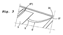
反射体ユニット2の縦方向の縁部2cに隣接する位置には、熱及び/又は光エネルギー収集手段3の逆側を向く長手方向支持型6aを配設する(図4)。
また、前記反射体スプリング5、5a、5bは、角部15もしくは角度付き延長部分を有するものとすることができ、これにより、この部分に作用する支持圧力を減少させる。
The curved shape of the cross section of the
A longitudinal support die 6a facing the opposite side of the heat and / or light energy collecting means 3 is disposed at a position adjacent to the
The reflector springs 5, 5a, 5b may have
この発明は、当然に、上記に例示した実施形態に限定して解釈されるものではなく、特許請求の範囲に記載した、この発明に従う基本的な着想の範囲内で変更を加えることができる。
とくに、それぞれの部材及び/又はカテゴリは、先に述べた技術的作用を実現するため、他の部材及び/又はカテゴリと組み合わせることができる。
Naturally, the present invention is not construed as being limited to the embodiments exemplified above, but can be modified within the scope of the basic idea according to the present invention described in the claims.
In particular, each member and / or category can be combined with other members and / or categories in order to achieve the technical actions described above.
Claims (16)
太陽光線に向けることが可能な、太陽光線を反射する反射体ユニット(2)及び、前記反射体ユニット(2)に連結された熱及び/又は光エネルギー吸収手段(3)を具え、
前記反射体ユニット(2)並びに、前記熱及び/又は光エネルギー吸収手段(3)を、透明な保護体(4)で被覆するとともに、前記反射体ユニット(2)の、主として反射体表面を、薄くて容易に湾曲可能な材料から形成し、
前記反射体ユニット(2)及び/又は前記反射体表面(2a)が、前記反射体ユニット(2)の縦方向の延在長さ(L)に沿って分配され、前記反射体表面(2a)の下方で、縦方向の延在長さ(L)と直交又は実質的に直交する向きに配設した複数の支持部材(2b)と連携するように構成されたことにより、前記反射体ユニット(2)及び/又は前記反射体表面(2a)が、安定した外形形状を維持しつつも、温度の影響に応じて、採用された形状及び/又は材料の選択によって決定される弾性域内で変形できるように構成された、装置(1)であって、
下方の前記支持部材(2b)に加えて、反射体スプリングとしての形態をなす支持部材(5、5a、5b)をさらに設け、該支持部材を、前記反射体ユニット(2)の反射表面もしくは前記反射体表面(2a)に支持させ、
太陽光の前記反射体表面(2a)の反射体形状の同一性を維持しつつ、前記反射体ユニット及び/又は前記反射体表面の、温度変化に起因する動きもしくは変位を許容するように、さらなる前記支持部材もしくは前記反射体スプリング(5)を、細いワイヤもしくは薄いストリップとして形成してなる装置。 Configured to absorb heat and / or light energy generated from received sunlight (B1, B2);
Which can be directed to sunlight, the reflector unit (2) that reflects sunlight and the concatenated heat and / or light energy absorption means (3) comprises said reflector unit (2),
It said reflector unit (2) as well as the heat and / or light energy absorption means (3), as well as coated with a transparent protective member (4), said reflector unit (2), mainly reflecting surface, Formed from a thin and easily bendable material,
Said reflector unit (2) and / or the reflector surface (2a) is, the reflector unit is distributed along the longitudinal direction of the extended length (L) of (2), the reflector surface (2a) at lower, by which is configured to work with the longitudinal direction of the extended length (L) and perpendicular or substantially perpendicular to the plurality of support members arranged in a direction (2b), the reflector unit ( 2) and / or the reflector surface (2a) is stabilized while maintaining the outer shape, depending on the influence of temperature, it adopted the shape and / or selected to result deformation of an elastic region which is determined material An apparatus (1) configured to be capable of:
In addition to the support member of the lower (2b), the support member (5, 5a, 5b) in the form of a reflector springs further provided, the support member, the reflecting surface or the reflector unit (2) Supported on the reflector surface (2a),
While maintaining the identity of the reflector shape of the reflector surface (2a) of the sunlight of the reflector unit and / or the reflector surface, to allow for movement or displacement caused by temperature changes, a further said support member or said reflector springs (5), made by forming a thin wire or a thin strip device.
Applications Claiming Priority (3)
| Application Number | Priority Date | Filing Date | Title |
|---|---|---|---|
| SE0702374-0 | 2007-10-22 | ||
| SE0702374A SE532465C2 (en) | 2007-10-22 | 2007-10-22 | Solar panels |
| PCT/SE2008/051182 WO2009054780A1 (en) | 2007-10-22 | 2008-10-21 | Solar energy concentrator |
Publications (2)
| Publication Number | Publication Date |
|---|---|
| JP2011501801A JP2011501801A (en) | 2011-01-13 |
| JP5416704B2 true JP5416704B2 (en) | 2014-02-12 |
Family
ID=40579765
Family Applications (1)
| Application Number | Title | Priority Date | Filing Date |
|---|---|---|---|
| JP2010530961A Expired - Fee Related JP5416704B2 (en) | 2007-10-22 | 2008-10-21 | Solar energy collector |
Country Status (13)
| Country | Link |
|---|---|
| US (1) | US20100243019A1 (en) |
| EP (1) | EP2201310A4 (en) |
| JP (1) | JP5416704B2 (en) |
| KR (1) | KR20100094471A (en) |
| CN (1) | CN101836056B (en) |
| AU (1) | AU2008317530B2 (en) |
| BR (1) | BRPI0818685A2 (en) |
| CA (1) | CA2702451A1 (en) |
| NZ (1) | NZ584639A (en) |
| RU (1) | RU2473849C2 (en) |
| SE (1) | SE532465C2 (en) |
| WO (1) | WO2009054780A1 (en) |
| ZA (1) | ZA201002577B (en) |
Families Citing this family (4)
| Publication number | Priority date | Publication date | Assignee | Title |
|---|---|---|---|---|
| KR101122819B1 (en) * | 2009-08-25 | 2012-04-20 | (주)티엠테크 | Apparatus for collecting solar energy |
| KR101420094B1 (en) | 2010-10-27 | 2014-07-17 | (주)바이오니아 | Automatic realtime PCR system for the various analysis of biological sample, method for Automatic nucleic acid purification and realtime quantification of gene amplification, method for automatic viable cell count of pathogenic bacteria using realtime quantitative PCR, method for automatically getting antigene density using quantitative immunity PCR |
| US10408497B2 (en) | 2016-06-09 | 2019-09-10 | James Rosa | Emergent platform diffuse light concentrating collector |
| US10001297B1 (en) * | 2017-02-20 | 2018-06-19 | James T Ganley | Free-hanging parabolic trough reflectors for solar energy conversion systems |
Family Cites Families (17)
| Publication number | Priority date | Publication date | Assignee | Title |
|---|---|---|---|---|
| US1951404A (en) * | 1930-12-10 | 1934-03-20 | Robert H Goddard | Focusing mirror and directing mechanism therefor |
| US4390241A (en) * | 1975-07-11 | 1983-06-28 | Vulcan Australia Limited | Reflective trough structure |
| US3991740A (en) * | 1975-07-28 | 1976-11-16 | The United States Of America As Represented By The United States Energy Research And Development Administration | Sea shell solar collector |
| US4103672A (en) * | 1976-05-21 | 1978-08-01 | Meyer Warren A | Solar collector |
| US4173397A (en) * | 1977-11-30 | 1979-11-06 | The United States Of America As Represented By The Administrator Of The National Aeronautics And Space Administration | Solar concentrator |
| US4678292A (en) * | 1981-05-01 | 1987-07-07 | Rca Corporation | Curved structure and method for making same |
| JPS5949154U (en) * | 1982-09-22 | 1984-04-02 | 昭和アルミニウム株式会社 | solar heat collector |
| JPS5993150A (en) * | 1982-11-17 | 1984-05-29 | Hitachi Ltd | Solar heat collector |
| US4596238A (en) * | 1983-08-26 | 1986-06-24 | Sunsteam Ltd. | Interiorly tensioned solar reflector |
| US4510923A (en) * | 1983-08-26 | 1985-04-16 | Bronstein Allen I | Solar reflector |
| US4571812A (en) * | 1984-02-16 | 1986-02-25 | Industrial Solar Technology | Method for making a solar concentrator and product |
| US5071243A (en) * | 1990-03-19 | 1991-12-10 | Bronstein Allen I | Tensioned cover for parabolic reflector |
| RU2075707C1 (en) * | 1995-09-19 | 1997-03-20 | Адамович Андрей Борисович | Heliokitchen |
| JP3724432B2 (en) * | 2001-04-19 | 2005-12-07 | 株式会社ニコン | Thin-film elastic structure, manufacturing method thereof, mirror device and optical switch using the same |
| RU2222755C1 (en) * | 2002-05-17 | 2004-01-27 | Государственное унитарное предприятие "НПО Астрофизика" | Solar plant |
| CN1800745A (en) * | 2006-01-18 | 2006-07-12 | 张耀明 | Solar concentrator lens with curved surface |
| FR2915217B1 (en) * | 2007-04-20 | 2009-07-10 | Imphy Alloys Sa | STRUCTURE FOR THE MOUNTING IN A WALL OF A BATIS BUILDING FOR SUPPORTING PANELS SUCH AS PHOTOVOLTAIC PANELS |
-
2007
- 2007-10-22 SE SE0702374A patent/SE532465C2/en not_active IP Right Cessation
-
2008
- 2008-10-21 JP JP2010530961A patent/JP5416704B2/en not_active Expired - Fee Related
- 2008-10-21 EP EP08842990.7A patent/EP2201310A4/en not_active Withdrawn
- 2008-10-21 US US12/739,068 patent/US20100243019A1/en not_active Abandoned
- 2008-10-21 CN CN2008801127572A patent/CN101836056B/en not_active Expired - Fee Related
- 2008-10-21 KR KR1020107011230A patent/KR20100094471A/en not_active Application Discontinuation
- 2008-10-21 AU AU2008317530A patent/AU2008317530B2/en not_active Ceased
- 2008-10-21 NZ NZ584639A patent/NZ584639A/en not_active IP Right Cessation
- 2008-10-21 BR BRPI0818685 patent/BRPI0818685A2/en not_active IP Right Cessation
- 2008-10-21 RU RU2010120656/06A patent/RU2473849C2/en not_active IP Right Cessation
- 2008-10-21 CA CA2702451A patent/CA2702451A1/en not_active Abandoned
- 2008-10-21 WO PCT/SE2008/051182 patent/WO2009054780A1/en active Application Filing
-
2010
- 2010-04-13 ZA ZA2010/02577A patent/ZA201002577B/en unknown
Also Published As
| Publication number | Publication date |
|---|---|
| SE532465C2 (en) | 2010-01-26 |
| NZ584639A (en) | 2011-12-22 |
| KR20100094471A (en) | 2010-08-26 |
| JP2011501801A (en) | 2011-01-13 |
| AU2008317530A1 (en) | 2009-04-30 |
| EP2201310A4 (en) | 2014-01-08 |
| WO2009054780A1 (en) | 2009-04-30 |
| EP2201310A1 (en) | 2010-06-30 |
| RU2473849C2 (en) | 2013-01-27 |
| RU2010120656A (en) | 2011-11-27 |
| CA2702451A1 (en) | 2009-04-30 |
| CN101836056B (en) | 2013-01-02 |
| AU2008317530B2 (en) | 2013-01-10 |
| SE0702374L (en) | 2009-04-23 |
| BRPI0818685A2 (en) | 2015-04-14 |
| CN101836056A (en) | 2010-09-15 |
| ZA201002577B (en) | 2010-12-29 |
| US20100243019A1 (en) | 2010-09-30 |
Similar Documents
| Publication | Publication Date | Title |
|---|---|---|
| US4158356A (en) | Self-powered tracking solar collector | |
| US4103672A (en) | Solar collector | |
| JP5797737B2 (en) | Solar heat collection system | |
| CA1090222A (en) | High efficiency solar collector | |
| US20020075579A1 (en) | Apparatus for collecting and converting radiant energy | |
| US3951128A (en) | Combined flat plate - focal point solar heat collector | |
| AU2007218174A1 (en) | Solar module system of the parabolic concentrator type | |
| WO2005090873A1 (en) | Solar collector | |
| KR101331623B1 (en) | Structure of combined solar thermal and solar photovoltaic system | |
| JP5416704B2 (en) | Solar energy collector | |
| US4230094A (en) | Solar concentrator | |
| US20020007830A1 (en) | Radiation heat collector | |
| US9115914B2 (en) | Collector and collector arrangement for generating heat from incident radiation | |
| CN101762079A (en) | Linear Fresnel solar heat collector | |
| WO2013014998A1 (en) | Light collector and light collecting apparatus provided with same | |
| WO2009045141A1 (en) | Solar concentrator | |
| US20100051088A1 (en) | Photovoltaic solar concentrating power system | |
| US4391269A (en) | Controlled solar heating and heat retention of liquid | |
| ES1162359U (en) | Solar energy concentrator with mobile mirrors for use in thermal solar surface caprators or in static photovoltaic modules. (Machine-translation by Google Translate, not legally binding) | |
| US10408497B2 (en) | Emergent platform diffuse light concentrating collector | |
| ES2427020B1 (en) | Solar concentration plant with optimized flat absorber | |
| KR100995821B1 (en) | Solar compound parabolic conentrator | |
| KR101155691B1 (en) | Vacuum tube type solar energy collecting pipe | |
| ES2570593B2 (en) | Multi-mode solar concentrator | |
| WO2014090330A1 (en) | A solar thermal vacuum tube collector |
Legal Events
| Date | Code | Title | Description |
|---|---|---|---|
| A711 | Notification of change in applicant |
Free format text: JAPANESE INTERMEDIATE CODE: A711 Effective date: 20101206 |
|
| A521 | Request for written amendment filed |
Free format text: JAPANESE INTERMEDIATE CODE: A821 Effective date: 20101206 |
|
| A621 | Written request for application examination |
Free format text: JAPANESE INTERMEDIATE CODE: A621 Effective date: 20110824 |
|
| A131 | Notification of reasons for refusal |
Free format text: JAPANESE INTERMEDIATE CODE: A131 Effective date: 20130108 |
|
| A601 | Written request for extension of time |
Free format text: JAPANESE INTERMEDIATE CODE: A601 Effective date: 20130405 |
|
| A602 | Written permission of extension of time |
Free format text: JAPANESE INTERMEDIATE CODE: A602 Effective date: 20130412 |
|
| A521 | Request for written amendment filed |
Free format text: JAPANESE INTERMEDIATE CODE: A523 Effective date: 20130426 |
|
| TRDD | Decision of grant or rejection written | ||
| A01 | Written decision to grant a patent or to grant a registration (utility model) |
Free format text: JAPANESE INTERMEDIATE CODE: A01 Effective date: 20131022 |
|
| A61 | First payment of annual fees (during grant procedure) |
Free format text: JAPANESE INTERMEDIATE CODE: A61 Effective date: 20131115 |
|
| R150 | Certificate of patent or registration of utility model |
Ref document number: 5416704 Country of ref document: JP Free format text: JAPANESE INTERMEDIATE CODE: R150 |
|
| R250 | Receipt of annual fees |
Free format text: JAPANESE INTERMEDIATE CODE: R250 |
|
| R250 | Receipt of annual fees |
Free format text: JAPANESE INTERMEDIATE CODE: R250 |
|
| R250 | Receipt of annual fees |
Free format text: JAPANESE INTERMEDIATE CODE: R250 |
|
| LAPS | Cancellation because of no payment of annual fees |