JP5416129B2 - 3D digital image projector - Google Patents
3D digital image projector Download PDFInfo
- Publication number
- JP5416129B2 JP5416129B2 JP2010537960A JP2010537960A JP5416129B2 JP 5416129 B2 JP5416129 B2 JP 5416129B2 JP 2010537960 A JP2010537960 A JP 2010537960A JP 2010537960 A JP2010537960 A JP 2010537960A JP 5416129 B2 JP5416129 B2 JP 5416129B2
- Authority
- JP
- Japan
- Prior art keywords
- light
- adjacent
- laser
- illumination
- projection
- Prior art date
- Legal status (The legal status is an assumption and is not a legal conclusion. Google has not performed a legal analysis and makes no representation as to the accuracy of the status listed.)
- Expired - Fee Related
Links
- 238000003384 imaging method Methods 0.000 claims abstract description 10
- 238000005286 illumination Methods 0.000 claims description 56
- 230000003287 optical effect Effects 0.000 claims description 56
- 230000003595 spectral effect Effects 0.000 claims description 45
- 230000010287 polarization Effects 0.000 claims description 29
- 238000001228 spectrum Methods 0.000 claims description 28
- 239000011521 glass Substances 0.000 claims description 15
- 230000001965 increasing effect Effects 0.000 abstract description 6
- 238000003491 array Methods 0.000 description 24
- 239000007787 solid Substances 0.000 description 20
- 238000000034 method Methods 0.000 description 18
- 238000013459 approach Methods 0.000 description 11
- 238000010586 diagram Methods 0.000 description 11
- 238000013461 design Methods 0.000 description 10
- 230000008901 benefit Effects 0.000 description 8
- 238000000576 coating method Methods 0.000 description 8
- 239000000463 material Substances 0.000 description 8
- 238000000926 separation method Methods 0.000 description 8
- 230000000712 assembly Effects 0.000 description 7
- 238000000429 assembly Methods 0.000 description 7
- 230000005540 biological transmission Effects 0.000 description 6
- 230000000694 effects Effects 0.000 description 6
- 239000011248 coating agent Substances 0.000 description 5
- 230000009977 dual effect Effects 0.000 description 5
- 238000004519 manufacturing process Methods 0.000 description 5
- 230000008569 process Effects 0.000 description 5
- 230000005855 radiation Effects 0.000 description 5
- 230000007704 transition Effects 0.000 description 5
- 239000010408 film Substances 0.000 description 4
- 239000013307 optical fiber Substances 0.000 description 4
- 238000007796 conventional method Methods 0.000 description 3
- 230000008878 coupling Effects 0.000 description 3
- 238000010168 coupling process Methods 0.000 description 3
- 238000005859 coupling reaction Methods 0.000 description 3
- 230000002708 enhancing effect Effects 0.000 description 3
- 230000010354 integration Effects 0.000 description 3
- 238000000465 moulding Methods 0.000 description 3
- 238000004806 packaging method and process Methods 0.000 description 3
- 239000004033 plastic Substances 0.000 description 3
- 229920003023 plastic Polymers 0.000 description 3
- 229910052724 xenon Inorganic materials 0.000 description 3
- FHNFHKCVQCLJFQ-UHFFFAOYSA-N xenon atom Chemical compound [Xe] FHNFHKCVQCLJFQ-UHFFFAOYSA-N 0.000 description 3
- XUIMIQQOPSSXEZ-UHFFFAOYSA-N Silicon Chemical compound [Si] XUIMIQQOPSSXEZ-UHFFFAOYSA-N 0.000 description 2
- BQCADISMDOOEFD-UHFFFAOYSA-N Silver Chemical compound [Ag] BQCADISMDOOEFD-UHFFFAOYSA-N 0.000 description 2
- 239000006117 anti-reflective coating Substances 0.000 description 2
- 230000008859 change Effects 0.000 description 2
- 239000003086 colorant Substances 0.000 description 2
- 239000000835 fiber Substances 0.000 description 2
- 239000004973 liquid crystal related substance Substances 0.000 description 2
- 229910052710 silicon Inorganic materials 0.000 description 2
- 239000010703 silicon Substances 0.000 description 2
- 229910052709 silver Inorganic materials 0.000 description 2
- 239000004332 silver Substances 0.000 description 2
- 239000000758 substrate Substances 0.000 description 2
- 230000002123 temporal effect Effects 0.000 description 2
- 239000010409 thin film Substances 0.000 description 2
- 230000000007 visual effect Effects 0.000 description 2
- VYPSYNLAJGMNEJ-UHFFFAOYSA-N Silicium dioxide Chemical compound O=[Si]=O VYPSYNLAJGMNEJ-UHFFFAOYSA-N 0.000 description 1
- NIXOWILDQLNWCW-UHFFFAOYSA-N acrylic acid group Chemical group C(C=C)(=O)O NIXOWILDQLNWCW-UHFFFAOYSA-N 0.000 description 1
- 230000002411 adverse Effects 0.000 description 1
- 238000000137 annealing Methods 0.000 description 1
- 230000000903 blocking effect Effects 0.000 description 1
- 230000001427 coherent effect Effects 0.000 description 1
- 238000001816 cooling Methods 0.000 description 1
- 238000012937 correction Methods 0.000 description 1
- 230000007423 decrease Effects 0.000 description 1
- 230000003247 decreasing effect Effects 0.000 description 1
- 230000007547 defect Effects 0.000 description 1
- 238000011161 development Methods 0.000 description 1
- 238000005516 engineering process Methods 0.000 description 1
- 238000001914 filtration Methods 0.000 description 1
- 210000003128 head Anatomy 0.000 description 1
- 230000004886 head movement Effects 0.000 description 1
- 238000010438 heat treatment Methods 0.000 description 1
- 238000000265 homogenisation Methods 0.000 description 1
- 230000031700 light absorption Effects 0.000 description 1
- 230000033001 locomotion Effects 0.000 description 1
- 238000002156 mixing Methods 0.000 description 1
- 238000012986 modification Methods 0.000 description 1
- 230000004048 modification Effects 0.000 description 1
- 239000005304 optical glass Substances 0.000 description 1
- 238000005498 polishing Methods 0.000 description 1
- 238000012545 processing Methods 0.000 description 1
- 238000011084 recovery Methods 0.000 description 1
- 230000009467 reduction Effects 0.000 description 1
- 239000004065 semiconductor Substances 0.000 description 1
- 230000035945 sensitivity Effects 0.000 description 1
- 239000000126 substance Substances 0.000 description 1
Images


Classifications
-
- H—ELECTRICITY
- H04—ELECTRIC COMMUNICATION TECHNIQUE
- H04N—PICTORIAL COMMUNICATION, e.g. TELEVISION
- H04N13/00—Stereoscopic video systems; Multi-view video systems; Details thereof
- H04N13/30—Image reproducers
- H04N13/332—Displays for viewing with the aid of special glasses or head-mounted displays [HMD]
- H04N13/334—Displays for viewing with the aid of special glasses or head-mounted displays [HMD] using spectral multiplexing
-
- G—PHYSICS
- G02—OPTICS
- G02B—OPTICAL ELEMENTS, SYSTEMS OR APPARATUS
- G02B27/00—Optical systems or apparatus not provided for by any of the groups G02B1/00 - G02B26/00, G02B30/00
- G02B27/10—Beam splitting or combining systems
- G02B27/1006—Beam splitting or combining systems for splitting or combining different wavelengths
- G02B27/102—Beam splitting or combining systems for splitting or combining different wavelengths for generating a colour image from monochromatic image signal sources
- G02B27/1026—Beam splitting or combining systems for splitting or combining different wavelengths for generating a colour image from monochromatic image signal sources for use with reflective spatial light modulators
-
- G—PHYSICS
- G02—OPTICS
- G02B—OPTICAL ELEMENTS, SYSTEMS OR APPARATUS
- G02B27/00—Optical systems or apparatus not provided for by any of the groups G02B1/00 - G02B26/00, G02B30/00
- G02B27/10—Beam splitting or combining systems
- G02B27/14—Beam splitting or combining systems operating by reflection only
- G02B27/143—Beam splitting or combining systems operating by reflection only using macroscopically faceted or segmented reflective surfaces
-
- G—PHYSICS
- G02—OPTICS
- G02B—OPTICAL ELEMENTS, SYSTEMS OR APPARATUS
- G02B27/00—Optical systems or apparatus not provided for by any of the groups G02B1/00 - G02B26/00, G02B30/00
- G02B27/10—Beam splitting or combining systems
- G02B27/14—Beam splitting or combining systems operating by reflection only
- G02B27/145—Beam splitting or combining systems operating by reflection only having sequential partially reflecting surfaces
-
- G—PHYSICS
- G02—OPTICS
- G02B—OPTICAL ELEMENTS, SYSTEMS OR APPARATUS
- G02B30/00—Optical systems or apparatus for producing three-dimensional [3D] effects, e.g. stereoscopic images
- G02B30/20—Optical systems or apparatus for producing three-dimensional [3D] effects, e.g. stereoscopic images by providing first and second parallax images to an observer's left and right eyes
- G02B30/22—Optical systems or apparatus for producing three-dimensional [3D] effects, e.g. stereoscopic images by providing first and second parallax images to an observer's left and right eyes of the stereoscopic type
- G02B30/25—Optical systems or apparatus for producing three-dimensional [3D] effects, e.g. stereoscopic images by providing first and second parallax images to an observer's left and right eyes of the stereoscopic type using polarisation techniques
-
- G—PHYSICS
- G03—PHOTOGRAPHY; CINEMATOGRAPHY; ANALOGOUS TECHNIQUES USING WAVES OTHER THAN OPTICAL WAVES; ELECTROGRAPHY; HOLOGRAPHY
- G03B—APPARATUS OR ARRANGEMENTS FOR TAKING PHOTOGRAPHS OR FOR PROJECTING OR VIEWING THEM; APPARATUS OR ARRANGEMENTS EMPLOYING ANALOGOUS TECHNIQUES USING WAVES OTHER THAN OPTICAL WAVES; ACCESSORIES THEREFOR
- G03B17/00—Details of cameras or camera bodies; Accessories therefor
- G03B17/48—Details of cameras or camera bodies; Accessories therefor adapted for combination with other photographic or optical apparatus
- G03B17/54—Details of cameras or camera bodies; Accessories therefor adapted for combination with other photographic or optical apparatus with projector
-
- G—PHYSICS
- G03—PHOTOGRAPHY; CINEMATOGRAPHY; ANALOGOUS TECHNIQUES USING WAVES OTHER THAN OPTICAL WAVES; ELECTROGRAPHY; HOLOGRAPHY
- G03B—APPARATUS OR ARRANGEMENTS FOR TAKING PHOTOGRAPHS OR FOR PROJECTING OR VIEWING THEM; APPARATUS OR ARRANGEMENTS EMPLOYING ANALOGOUS TECHNIQUES USING WAVES OTHER THAN OPTICAL WAVES; ACCESSORIES THEREFOR
- G03B19/00—Cameras
- G03B19/18—Motion-picture cameras
- G03B19/22—Double cameras
-
- G—PHYSICS
- G03—PHOTOGRAPHY; CINEMATOGRAPHY; ANALOGOUS TECHNIQUES USING WAVES OTHER THAN OPTICAL WAVES; ELECTROGRAPHY; HOLOGRAPHY
- G03B—APPARATUS OR ARRANGEMENTS FOR TAKING PHOTOGRAPHS OR FOR PROJECTING OR VIEWING THEM; APPARATUS OR ARRANGEMENTS EMPLOYING ANALOGOUS TECHNIQUES USING WAVES OTHER THAN OPTICAL WAVES; ACCESSORIES THEREFOR
- G03B30/00—Camera modules comprising integrated lens units and imaging units, specially adapted for being embedded in other devices, e.g. mobile phones or vehicles
-
- H—ELECTRICITY
- H04—ELECTRIC COMMUNICATION TECHNIQUE
- H04N—PICTORIAL COMMUNICATION, e.g. TELEVISION
- H04N13/00—Stereoscopic video systems; Multi-view video systems; Details thereof
- H04N13/30—Image reproducers
- H04N13/363—Image reproducers using image projection screens
-
- H—ELECTRICITY
- H04—ELECTRIC COMMUNICATION TECHNIQUE
- H04N—PICTORIAL COMMUNICATION, e.g. TELEVISION
- H04N9/00—Details of colour television systems
- H04N9/12—Picture reproducers
- H04N9/31—Projection devices for colour picture display, e.g. using electronic spatial light modulators [ESLM]
- H04N9/3141—Constructional details thereof
- H04N9/315—Modulator illumination systems
- H04N9/3152—Modulator illumination systems for shaping the light beam
-
- H—ELECTRICITY
- H04—ELECTRIC COMMUNICATION TECHNIQUE
- H04N—PICTORIAL COMMUNICATION, e.g. TELEVISION
- H04N9/00—Details of colour television systems
- H04N9/12—Picture reproducers
- H04N9/31—Projection devices for colour picture display, e.g. using electronic spatial light modulators [ESLM]
- H04N9/3141—Constructional details thereof
- H04N9/315—Modulator illumination systems
- H04N9/3161—Modulator illumination systems using laser light sources
-
- H—ELECTRICITY
- H04—ELECTRIC COMMUNICATION TECHNIQUE
- H04N—PICTORIAL COMMUNICATION, e.g. TELEVISION
- H04N9/00—Details of colour television systems
- H04N9/12—Picture reproducers
- H04N9/31—Projection devices for colour picture display, e.g. using electronic spatial light modulators [ESLM]
- H04N9/3141—Constructional details thereof
- H04N9/315—Modulator illumination systems
- H04N9/3164—Modulator illumination systems using multiple light sources
-
- H—ELECTRICITY
- H04—ELECTRIC COMMUNICATION TECHNIQUE
- H04N—PICTORIAL COMMUNICATION, e.g. TELEVISION
- H04N9/00—Details of colour television systems
- H04N9/12—Picture reproducers
- H04N9/31—Projection devices for colour picture display, e.g. using electronic spatial light modulators [ESLM]
- H04N9/3197—Projection devices for colour picture display, e.g. using electronic spatial light modulators [ESLM] using light modulating optical valves
Abstract
Description
本発明は、一般に、立体的デジタル画像を投影するための装置に関し、より詳細には個別の複数の波長を使用してデジタル映画投影用の立体画像を作成する改善された装置および方法に関する。 The present invention relates generally to an apparatus for projecting a stereoscopic digital image, and more particularly to an improved apparatus and method for creating a stereoscopic image for digital cinema projection using a plurality of discrete wavelengths.
従来のフィルム映写機の適切な代替品として見なされるためには、デジタル投影システムは、画質に関する厳しい要件を満たさなければならない。これは、特に、多色映画投影システムに当てはまる。従来の映画品質プロジェクタに匹敵するデジタル投影代替品は、高解像度、広色域、高輝度、および1000:1を超える面順次コントラスト比を実現する高い性能基準を満たさなければならない。 In order to be considered a suitable replacement for conventional film projectors, digital projection systems must meet stringent image quality requirements. This is especially true for multicolor movie projection systems. Digital projection alternatives comparable to conventional movie quality projectors must meet high performance standards that achieve high resolution, wide color gamut, high brightness, and frame-sequential contrast ratios exceeding 1000: 1.
映画産業は、大きな会場で観客に高品質な視覚的経験を提供するために、三次元(3D)または立体的に見えるコンテンツを生成し表示するようになってきている。Disneyなどの娯楽会社は、そのテーマパークで長年このコンテンツを提供し、Imaxは、そのようなコンテンツ専用の劇場を作成してきたが、そのような両方の事例で、フィルムは画像作成の主要媒体であった。立体像を作成するために、2組のフィルムとプロジェクタが同時にそれぞれの目に1つの直角偏光を投影する。観客は、これに対応して、それぞれの目に1つの偏光画像を遮断し同時に直角偏光画像を透過する直角偏光メガネを装着する。 The movie industry is generating and displaying content that looks three-dimensional (3D) or stereoscopic in order to provide a high-quality visual experience to the audience at large venues. Entertainment companies such as Disney have provided this content for many years in its theme parks, and Imax has created theaters dedicated to such content, but in both cases, film is the primary medium for image creation. there were. To create a stereoscopic image, two sets of film and projector simultaneously project one orthogonal polarization into each eye. Correspondingly, the audience wears right-polarized glasses that block one polarized image in each eye and simultaneously transmit the right-polarized image.
映画産業がデジタル画像に移行する際、Imaxなどのいくつかのベンダーは、高品質立体像を提供するためにずっと二投影システムを利用してきている。しかしながら、より一般には、従来のデジタル・プロジェクタが、三次元投影を可能にするように修正されている。 As the movie industry transitions to digital images, some vendors such as Imax have long utilized two-projection systems to provide high quality stereoscopic images. More generally, however, conventional digital projectors have been modified to allow three-dimensional projection.
多色デジタル映画投影のそのような従来の投影解決策のうちで最も有望なものは、画像形成装置として、2つの基本的なタイプの空間光変調器(SLM)の一方を使用する。第1のタイプの空間光変調器は、テキサス州ダラスのTexas Instruments, Inc.によって開発されたデジタル光プロセッサ(DLP)、デジタル・マイクロミラー装置(DMD)である。DLP装置は、いくつかの特許、例えば、特許文献1、特許文献2、特許文献3、および特許文献4に記載されている。DLPを使用する投影装置の光学設計は、特許文献5、特許文献6、特許文献7および特許文献8に記載されている。DLPは、デジタル投影システムに首尾よく使用されてきている。
The most promising of such conventional projection solutions for multi-color digital cinema projection uses one of two basic types of spatial light modulators (SLMs) as the imaging device. The first type of spatial light modulator is a digital light processor (DLP), digital micromirror device (DMD) developed by Texas Instruments, Inc. of Dallas, Texas. The DLP device is described in several patents, for example,
図1は、DLP空間光変調器を使用するプロジェクタ装置10の簡略化されたブロック図を示す。光源12は、多色非偏光を、例えばフィリップス・プリズムなどのプリズム組立体14内に提供する。プリズム組立体14は、多色光を赤色、緑色および青色成分の波長域に分割し、各波長域を対応する空間光変調器20r、20gまたは20bに導く。次に、プリズム組立体14は、各SLM20r、20gおよび20bからの変調光を再結合させ、この非偏光を、表示スクリーンや他の適切な面に投影するための映写レンズ30に提供する。
FIG. 1 shows a simplified block diagram of a
DLPを利用したプロジェクタは、デスクトップ画面から大型映画までほとんどの投影用途に必要な光処理能力、コントラスト比および色域を提供する能力を持つ。しかしながら、一般に最大2148×1080画素しか提供しない既存の装置では、本来、解像度に限界がある。更に、構成要素およびシステム・コストが高いため、DLP設計をより高品質のデジタル映画投影に適用するのは制限されていた。さらに、フィリップスや他の適切な結合プリズムのコスト、サイズ、重量および複雑さが、大きな制約になっている。更に、輝度要件のために作動距離が長く比較的明るい映写レンズが必要なことは、そのような装置の受容性と有用性に悪影響を及ぼしていた。 Projectors using DLP have the light processing capability, contrast ratio, and color gamut needed for most projection applications, from desktop screens to large movies. However, existing devices that generally provide only a maximum of 2148 × 1080 pixels are inherently limited in resolution. In addition, the high component and system costs have limited the application of DLP designs to higher quality digital cinema projections. In addition, the cost, size, weight and complexity of Philips and other suitable coupling prisms are major constraints. In addition, the need for a relatively bright projection lens due to luminance requirements has adversely affected the acceptability and usefulness of such devices.
デジタル投影に使用される第2のタイプの空間光変調器は、LCD(液晶デバイス)である。LCDは、入射光の偏光状態を対応する画素ごとに選択的に変調することによって、画像を画素アレイとして形成する。LCDは、高品質デジタル映画投影システム用の空間光変調器として利点を有すると考えられる。そのような利点には、比較的大きい装置サイズ、好ましい装置歩留まり、およびより高い解像度装置(例えば、ソニー株式会社と日本ビクター株式会社による4096×2160解像度装置)を製造できることがある。LCD空間光変調器を利用する電子投影装置の例には、特許文献9、特許文献10、特許文献11、特許文献12、および特許文献13に開示されたものがある。大型画像投影にはLCOS(Liquid Crystal On Silicon)装置が特に有望と思われる。しかしながら、高輝度投影の高い熱負荷が、材料の偏光品質に影響を及ぼすので、LCD構成要素は、特に色とコントラストに関するデジタル映画の高い品質要求を維持するのが難しい。
A second type of spatial light modulator used for digital projection is an LCD (Liquid Crystal Device). The LCD forms an image as a pixel array by selectively modulating the polarization state of incident light for each corresponding pixel. LCDs are believed to have advantages as spatial light modulators for high quality digital movie projection systems. Such advantages include the ability to produce relatively large device sizes, preferred device yields, and higher resolution devices (eg, 4096 × 2160 resolution devices from Sony Corporation and Victor Corporation). Examples of the electronic projection apparatus using the LCD spatial light modulator include those disclosed in Patent Literature 9,
そのような従来のマイクロディスプレイ(DLPまたはLCOS)を利用したプロジェクタから立体像を形成する従来の方法は、2つの主要な技術を利用している。例えばDolby Laboratoriesによって利用されているあまり一般的でない技術は、Maximusらによる特許文献14に記載されたものと類似しており、この技術は、色空間分離を使用して左目と右目のコンテンツを区別する。白色光照明システムでは、フレーム時間の一部分の間、各原色の一部分を瞬間的に遮断するためにフィルタが利用される。例えば、左目の場合、赤、青および緑(RGB)の低い方の波長スペクトルが、ある時間期間遮断される。その後で、他方の目の赤、青および緑(RGB)の高い方の波長スペクトルが遮断される。それぞれの目と関連付けられた適切な色調整された立体コンテンツが、目のための各変調器に提示される。視聴者は、2つの3色(RGB)スペクトル・セットのうちの一方だけを同様に透過する対応するフィルタ・セットを装着する。このシステムは、特注の偏光保持スクリーンを利用することなく画像をほとんどのスクリーンに投影できるという点で、偏光式投影システムより有利である。同様に、この手法を実施する際に、変調器または関連光学素子の偏光特性が重要でない点が有利である。しかしながら、フィルタ・メガネが高価であり、また角度のずれ、頭の動きおよび傾きによって視聴品質が低下する可能性があるという欠点がある。また、高価なメガネは、引っ掻き傷や盗難を受けて会場所有者の資金問題を引き起こしやすい。さらに、色空間の調整が困難なことがあり、またフィルタリングによる大きな光損失があり、それにより、必要なランプ出力が高くなるか、画像輝度が低下することになる。 The conventional method for forming a stereoscopic image from a projector using such a conventional micro display (DLP or LCOS) utilizes two main techniques. For example, the less common technique utilized by Dolby Laboratories is similar to that described by Maximus et al. In US Pat. No. 6,057,096, which uses color space separation to distinguish left and right eye content. To do. In white light illumination systems, filters are used to momentarily block a portion of each primary color during a portion of the frame time. For example, in the case of the left eye, the lower wavelength spectrum of red, blue and green (RGB) is blocked for a period of time. Thereafter, the higher wavelength spectrum of red, blue and green (RGB) of the other eye is blocked. Appropriate color adjusted stereoscopic content associated with each eye is presented to each modulator for the eye. The viewer wears a corresponding filter set that similarly transmits only one of the two three-color (RGB) spectral sets. This system has the advantage over the polarizing projection system in that the image can be projected on most screens without the use of a custom polarization maintaining screen. Similarly, when performing this approach, it is advantageous that the polarization characteristics of the modulator or associated optical element are not critical. However, there are drawbacks that the filter glasses are expensive and the viewing quality may be deteriorated due to the angle shift, head movement and tilt. Also, expensive glasses are likely to cause venue owners funding problems due to scratches and theft. In addition, the color space may be difficult to adjust and there may be significant light loss due to filtering, which increases the required lamp output or reduces image brightness.
第2の手法は、偏光を利用する。オレゴン州ウィルソンヴィルのInFocus Corporationに譲渡された特許文献15の1つの方法は、2つの別個の空間光変調器にそれぞれ送られる2つの直交偏光状態を利用する。両方の変調器からの偏光が同時に投影される。視聴者は、互いに直角に向けられた左目と右目用の偏光透過軸を有する偏光メガネを装着する。この構成は、光の効率的な使用を可能にするが、特に各色域ごとに空間光変調器が必要とされるプロジェクタ設計では、構成がきわめて高価になる可能性がある。偏光を使用する別のより一般的な手法では、従来のデジタル・プロジェクタが、ある状態から他の状態に迅速に切り替えられる交互の偏光状態を変調するように改良される。これは、例えば、DLPプロジェクタが、光の出力経路内(図1に破線によって示された位置16など)に配置された偏光子を有する場合に行うことができる。この偏光子は、複屈折を引き起こす応力によりデバイス・パッケージの窓が偏光解消するので、DLPが本質的に入力光の偏光を維持するように設計されないので必要とされる。偏光子の後の位置16に、特許文献16に記載されたタイプと類似の色消し偏光スイッチが使用されてもよい。あるいは、このタイプの切替器が、偏光を直線偏光状態などの2つの直交偏光状態の間で交互に回転させて、ユーザが偏光メガネを装着しているときにそれぞれの目に2つの別個の画像の表現を可能にする。
The second technique uses polarized light. One method of U.S. Patent No. 6,053,096, assigned to InFocus Corporation of Wilsonville, Oregon, utilizes two orthogonal polarization states that are respectively sent to two separate spatial light modulators. Polarized light from both modulators is projected simultaneously. The viewer wears polarized glasses having polarization transmission axes for the left eye and the right eye that are oriented at right angles to each other. This configuration allows for efficient use of light, but can be very expensive, especially in projector designs where a spatial light modulator is required for each color gamut. In another more general approach that uses polarization, a conventional digital projector is modified to modulate alternating polarization states that can be quickly switched from one state to another. This can be done, for example, when the DLP projector has a polarizer placed in the light output path (such as
リアルDシステム(Real-D system)は、従来から左円偏光と右円偏光を利用してきており、メガネは、一方の状態を遮断する前に円偏光を直線偏光に戻す4分の1波長リターダと偏光子の組合せからなる。これは、明らかに頭の傾きの影響を受けにくく、色消し偏光スイッチは製造しやすい。しかしながら、このメガネは、偏光子をだけ使用する実施形態より費用が増える。いずれにしても、表示スクリーンは、入射した画像を含む光の偏光状態を実質的に維持しなければならず、したがって一般に銀被覆される。銀被覆スクリーンは、コストが高くなり、利得に関して角感度を示す。このシステムはある程度の価値があるが、MEMS(マイクロ電気機械システム)システムでは、偏光を必要とするので大きな光損失があり、これにより、出力が半分に減少する。同様に、偏光スイッチによって光損失が増えコストが高くなる。この方法を利用するLCOSプロジェクタは、装置が機能するために出力が一般に既に偏光されているという点で、典型的なMEMSプロジェクタより優れている。したがって、出力光を偏光させることによって大きな損失とならない。しかしながら、これらのプロジェクタは、一般に、高角度光学素子によって高い偏光制御を維持することが難しいので、コストが高くなる。したがって、効率の改善は、他のコストによってある程度相殺される。 The Real-D system has traditionally used left-handed and right-handed circularly polarized light, and glasses use a quarter-wave retarder to return circularly-polarized light to linearly-polarized light before blocking one state. And a polarizer. This is clearly less susceptible to head tilt and achromatic polarization switches are easier to manufacture. However, the glasses are more expensive than embodiments using only polarizers. In any case, the display screen must substantially maintain the polarization state of the light containing the incident image and is therefore generally silver coated. Silver-coated screens are costly and exhibit angular sensitivity with respect to gain. Although this system is of some value, MEMS (microelectromechanical system) systems require polarization and therefore have a large light loss, which reduces the output in half. Similarly, the polarization switch increases the optical loss and increases the cost. LCOS projectors that utilize this method are superior to typical MEMS projectors in that the output is generally already polarized for the device to function. Therefore, there is no significant loss by polarizing the output light. However, these projectors generally have high costs because it is difficult to maintain high polarization control with high-angle optical elements. Thus, efficiency improvements are offset to some extent by other costs.
照明効率に関する継続的な問題は、エタンデュ(etendue)または同様にラグランジュ不変式(Lagrange invariant)に関連する。光学技術において周知のとおり、エタンデュは、光学システムが処理することができる光の量に関連する。エタンデュが大きいほど画像が明るくなる可能性がある。数値的には、エタンデュは2つの因子の積、すなわち画像域と開口数の積に比例する。光源12、光学素子18および空間光変調器20を有する図2に示した単純化された光学システムの場合、エタンデュは、光源の面積A1とその出力角度θ1の因子であり、また変調器の面積A2とその受け入れ角度θ2に等しい。輝度が高い場合、光源12の領域からできるだけ多くの光を提供することが望ましい。一般的な原理として、光学設計は、光源のエタンデュが変調器のエタンデュに最もきっちりと整合したときに有利である。
A continuing problem with lighting efficiency is related to etendue or likewise Lagrange invariant. As is well known in the optical arts, etendue relates to the amount of light that an optical system can process. The larger the etendue, the brighter the image. Numerically, etendue is proportional to the product of two factors: the image area and the numerical aperture. For the simplified optical system shown in FIG. 2 with
例えば、開口数を大きくするとエタンデュが大きくなり、それにより、光学システムが得る光が増える。同様に、元の画像サイズを大きくすると、光が生じる面積が大きくなり、エタンデュが大きくなる。照明側で大きいエタンデュを利用するには、エタンデュは、照明源のものより大きいかまたはそれと等しくなければならない。しかしながら、一般的に、画像が大きいほどコストがかかる。これは、特に、シリコン基板と欠陥可能性がサイズと共に増大するLCOS構成要素やDLP構成要素などの装置に当てはまる。概して、エタンデュが大きくなると複雑になり光学設計のコストが増える。例えば、特許文献17に略述されたような手法を使用すると、光学システム内のレンズ構成要素のエタンデュを大きくするように設計しなければならない。システム光学素子によって集束しなければならない光の元の画像面積は、赤色、緑色および青色光経路内の空間光変調器の合成面積の和であり、特に、これは、形成された最終的な多色画像の面積の3倍である。すなわち、特許文献17で開示された構成では、赤色、緑色および青色経路が独立しており、光学的に集束されなければならないので、光学構成要素は、かなり大きな画像領域、したがって高いエタンデュを処理しなければならない。さらに、特許文献17に開示されたような構成は、形成された最終的な多色画像の3倍の面積からの光を処理するが、この構成は、各色経路が全光レベルの3分の1しか含まないので、輝度が高いという利点を提供しない。 For example, increasing the numerical aperture increases the etendue, thereby increasing the light that the optical system obtains. Similarly, when the original image size is increased, the area where light is generated increases and the etendue increases. In order to utilize a large etendue on the illumination side, the etendue must be greater than or equal to that of the illumination source. However, generally, the larger the image, the higher the cost. This is especially true for devices such as LCOS and DLP components where the silicon substrate and defect potential increase with size. In general, as Etendue becomes larger, it becomes more complex and increases the cost of optical design. For example, using a technique such as that outlined in US Pat. No. 6,057,059, the lens component in the optical system must be designed to increase the etendue. The original image area of the light that must be focused by the system optics is the sum of the combined area of the spatial light modulators in the red, green, and blue light paths, and in particular, this is the final multiple formed. Three times the area of the color image. That is, in the configuration disclosed in US Pat. No. 6,057,059, the red, green and blue paths are independent and must be optically focused, so that the optical component handles a fairly large image area and thus high etendue. There must be. Furthermore, a configuration such as that disclosed in US Pat. No. 6,053,836 processes light from three times the area of the final multicolor image formed, but this configuration has each color path at 3/3 of the total light level. Since only 1 is included, the advantage of high brightness is not provided.
効率は、光源のエタンデュが空間光変調器のエタンデュとよく一致するときに改善する。エタンデュがあまり一致しないと、光学システムが、光量不足で空間光変調器に十分な光を提供できないか、変調のために生成された光の大部分が非効率的に実質的に廃棄される。 Efficiency improves when the etendue of the light source closely matches the etendue of the spatial light modulator. If the etendue does not match very much, the optical system cannot provide enough light to the spatial light modulator due to insufficient light, or most of the light generated for modulation is substantially discarded inefficiently.
許容可能なシステム・コストでデジタル映画用途に十分な輝度を提供する目的は、LCDシステムとDLPシステム両方の設計者を困惑させてきた。LCDシステムは、偏光の要件によって性能が損なわれ、偏光回復技術が使用される場合でも、効率が低下しエタンデュが増大した。DLPデバイスの設計は、偏光を必要とせず、多少効率が高いことが分かっているが、高価で短寿命のランプとコストの高い光学エンジンも必要なので、高価過ぎて従来の映画投影機器と競合できない。 The objective of providing sufficient brightness for digital cinema applications at an acceptable system cost has been confusing for designers of both LCD and DLP systems. LCD systems suffered from performance due to polarization requirements, and even when polarization recovery technology was used, efficiency decreased and etendue increased. The DLP device design does not require polarization and is known to be somewhat more efficient, but it also requires expensive, short-lived lamps and costly optical engines, so it is too expensive to compete with traditional movie projection equipment .
従来の高性能フィルム投影システムと競合しかつ電子またはデジタル映画と名付けられたものを提供するために、デジタル・プロジェクタは、この初期の機器に匹敵する映画輝度レベルを達成できなければならない。規模の見当として、典型的な劇場は、対角線で約40フィートのスクリーン・サイズに投影するのに約10,000ルーメンを必要とする。スクリーン範囲では、どの場所でも5,000ルーメンから40,000ルーメン以上を必要とする。この厳しい要求の輝度要件に加えて、これらのプロジェクタは、高解像度(2048x1080画素)を出力し、約2000:1のコントラストと広い色域も提供しなければならない。 In order to compete with conventional high performance film projection systems and provide what is termed electronic or digital cinema, digital projectors must be able to achieve movie brightness levels comparable to this early device. As a scale estimate, a typical theater requires about 10,000 lumens to project diagonally to a screen size of about 40 feet. The screen range requires anywhere from 5,000 lumens to over 40,000 lumens. In addition to this stringent luminance requirement, these projectors must output high resolution (2048 x 1080 pixels) and provide approximately 2000: 1 contrast and a wide color gamut.
いくつかのデジタル映画プロジェクタ設計は、この性能レベルが可能であることが分かっている。しかしながら、高い機器コストと運用コストが障害であった。これらの要件を満たす投影装置は、一般に、それぞれ50,000ドルを超えるコストがかかり、またしばしば1000ドルを超える典型的な交換コストで500〜2000時間の間隔で交換を必要とする高ワット数キセノン・アーク・ランプを利用する。キセノン・ランプの大きなエタンデュは、そのような光源から光を収集し投影するために比較的明るい光学素子を必要とするので、コストと複雑さにかなり影響を及ぼす。 Some digital movie projector designs have been found to be capable of this performance level. However, high equipment cost and operation cost were obstacles. Projectors that meet these requirements generally cost more than $ 50,000 each, and high wattage xenon that requires replacement at intervals of 500-2000 hours with typical replacement costs often exceeding $ 1000・ Use arc lamps. The large etendue of xenon lamps has a significant impact on cost and complexity because it requires relatively bright optics to collect and project light from such light sources.
DLP空間光変調器とLCOS LCD空間光変調器(SLM)の両方に共通の1つの欠点は、固体光源(詳細にはレーザ源)を使用する能力に制限があることであった。固体光源は、相対的スペクトル純度と潜在的に高い輝度レベルが他のタイプの光源より有利であるが、これらの利点を有効に使用するために様々な手法を必要とする。初期のデジタル・プロジェクタに関して説明されたように光源からの光を調整し、方向変更し、結合するために従来の方法と装置を使用することにより、レーザ・アレイ光源をどの程度使用できるかが制限を受ける可能性がある。 One drawback common to both DLP spatial light modulators and LCOS LCD spatial light modulators (SLMs) has been the limited ability to use solid state light sources (specifically laser sources). Solid state light sources are advantageous over other types of light sources in relative spectral purity and potentially high brightness levels, but require various approaches to effectively use these advantages. Limit the extent to which laser array light sources can be used by using conventional methods and equipment to adjust, redirect, and combine light from the light source as described for early digital projectors There is a possibility of receiving.
固体レーザは、エタンデュ、寿命、および全体のスペクトル/輝度安定性の改善を約束するが、最近まで、可視光をデジタル映画に十分なレベルと許容可能なコストで送出できなかった。より最近の開発で、VCSEL(面発光レーザ)レーザ・アレイが商業化され、光源としてのある程度の将来性がある。しかしながら、輝度自体まだ十分に高くなく、各色に必要な輝度を提供するためには、9つもの個別アレイからの組み合わせ光が必要とされる。 Solid state lasers promise to improve etendue, lifetime, and overall spectral / brightness stability, but until recently, visible light could not be delivered to digital movies at a sufficient level and at an acceptable cost. With more recent development, VCSEL (surface emitting laser) laser arrays have been commercialized and have some potential as light sources. However, the luminance itself is not yet high enough and combined light from as many as nine individual arrays is required to provide the necessary luminance for each color.
レーザ・アレイを使用する投影装置の例には以下のものがある。 Examples of projection devices that use laser arrays include:
特許文献18は、プロジェクタ照明用のマイクロレーザ・アレイの使用について述べている。 U.S. Pat. No. 6,057,034 describes the use of a microlaser array for projector illumination.
特許文献19は、空間光変調器にレーザ照明を提供するための有機レーザの使用について述べている。 U.S. Patent No. 6,057,033 describes the use of an organic laser to provide laser illumination to a spatial light modulator.
特許文献20は、照明用の拡張面発光半導体レーザ・アレイの使用について述べている。 U.S. Pat. No. 6,057,034 describes the use of an extended surface emitting semiconductor laser array for illumination.
特許文献21は、プロジェクタ照明用のマイクロレーザ・アレイを使用する様々な表示装置実施形態について述べている。 U.S. Patent No. 6,057,031 describes various display device embodiments that use microlaser arrays for projector illumination.
特許文献22は、高冷却効率を有する従来のレーザ・バーおよびエッジ発光ダイオードのパッケージングについて述べており、平行ビーム間の間隔をなくすかまたは少なくすることによって二次元アレイの発散サイズ積(divergence-size product)(エタンデュ)を小さくするリフレクタと組み合わされたレンズの使用について述べている。 U.S. Patent No. 6,057,031 describes conventional laser bar and edge light emitting diode packaging with high cooling efficiency, and eliminates or reduces the spacing between parallel beams to reduce the divergence-size product of a two-dimensional array. Describes the use of lenses combined with reflectors to reduce size product.
なお、特許文献18は、「Laser Illuminated Image Projection System and Method of Using Same」と題するKappelらによる米国特許第5,704,700号である。
特許文献19は、「Electronic Imaging System Using Organic Laser Array Illuminating an Area Light Valve」と題するKruschwitzらの同一出願人による米国特許第6,950,454号である。特許文献20は、「Projection Display Apparatus, System, and Method」と題するMooradianらによる米国特許出願公開第2006/0023173号である。特許文献21は、「Displays Using Solid-State Light Sources」と題するGlennによる米国特許第7,052,145号である。特許文献22は、「Laser Diode Array Assemblies With Optimized Brightness Conservation」と題するLangらによる米国特許第6,240,116号である。
Patent document 19 is US Pat. No. 6,950,454 by Kruschwitz et al., Entitled “Electronic Imaging System Using Organic Laser Array Illuminating an Area Light Valve”. US Patent Application Publication No. 2006/0023173 by Mooradian et al. Entitled "Projection Display Apparatus, System, and Method". US Pat. No. 7,052,145 by Glenn entitled “Displays Using Solid-State Light Sources”. US Pat. No. 6,240,116 by Lang et al. Entitled “Laser Diode Array Assemblies With Optimized Brightness Conservation”.
これらのタイプそれぞれの解決策には問題がある。特許文献18は、画像投影において光源として使用するためのコヒーレント・レーザのモノリシック・アレイの使用を教示しており、それにより、レーザの数は、プロジェクタのルーメン出力の出力要件を満たすように選択される。しかしながら、高ルーメン・プロジェクタにおいて、この手法にはいくつかの問題が生じる。装置の数が増えるほど生産留まりが低下し、アレイの規模が大きいほど熱問題が大きくなる可能性がある。また、コヒーレンスが、モノリシック設計の問題を引き起こす可能性がある。レーザ源のコヒーレンスは、一般に、光学干渉や斑点などのアーティファクトを発生させる。したがって、コヒーレンス、空間および時間コヒーレンスが弱いかまたは無視できるレーザ・アレイを使用することが望ましい。スペクトル・コヒーレンスは、色域を改善する観点からは望ましいが、スペクトル広がりの少ないことは、干渉と斑点の影響を少なくするのに望ましく、また単一スペクトル源の色ずれ効果も減少させる。この色ずれは、例えば、別個の赤色、緑色および青色レーザ源を有する三色投影システムで生じる可能性がある。単一色アレイのすべてのレーザが繋がった狭い波長のものであり、動作波長にずれが生じた場合、白色点とプロジェクタ全体の色が仕様から外れる可能性がある。一方、アレイが、波長の小さなばらつきで平均化された場合は、出力全体の単一色のずれの影響が大幅に減少する。Kappelが述べているようにこのコヒーレンスを破壊するのに役立つ構成要素がシステムに追加されてもよいが、コストと単純性の観点から、様々な生産ロットからのわずかに異なるデバイスを利用して実質的に非コヒーレンスなレーザ源を構成することが好ましい。更に、この非コヒーレンスをレーザ源以上に減少させるほとんどの手段は、レーザ源の有効度(エタンデュ)を高め、光損失を増大させ、システムのコストを高めるディフューザなどの構成要素を利用するので、レーザ源での空間的および時間的コヒーレンスを減少させることが好ましい。レーザのエタンデュを小さく維持することにより、照明用の光学トレインを単純化することができ、これはきわめて望ましい。 There are problems with each of these types of solutions. U.S. Pat. No. 6,057,031 teaches the use of a monolithic array of coherent lasers for use as a light source in image projection, whereby the number of lasers is selected to meet the output requirements of the projector lumen output. The However, there are several problems with this approach for high lumen projectors. The production yield decreases as the number of devices increases, and the thermal problem can increase as the size of the array increases. Coherence can also cause monolithic design problems. The coherence of a laser source generally generates artifacts such as optical interference and spots. Therefore, it is desirable to use a laser array with weak or negligible coherence, space and temporal coherence. Spectral coherence is desirable from the standpoint of improving color gamut, but less spectral broadening is desirable to reduce the effects of interference and speckle, and also reduces the color shift effects of a single spectral source. This color shift can occur, for example, in a three color projection system with separate red, green and blue laser sources. If all lasers of a single color array are connected to each other and have a narrow wavelength, if the operating wavelength is shifted, the white point and the color of the entire projector may be out of specification. On the other hand, if the array is averaged with small variations in wavelength, the effect of a single color shift across the output is greatly reduced. Components that help destroy this coherence may be added to the system, as Kappel states, but in terms of cost and simplicity, it is practical to utilize slightly different devices from different production lots. It is preferable to construct an incoherent laser source. In addition, most means to reduce this incoherence over the laser source utilize components such as diffusers that increase the effectiveness of the laser source (etendue), increase optical loss, and increase system cost. It is preferable to reduce the spatial and temporal coherence at the source. By keeping the laser etendue small, the optical train for illumination can be simplified, which is highly desirable.
特に投影用途を対象とするレーザ・アレイは、カリフォルニア州サニーベイルのNovaluxによるVECSEL(垂直外部共振器型面発光レーザ)とNECSEL(Novalux外部共振器型面発光レーザ)装置を含む様々なタイプのVCSELアレイである。しかしながら、これらの装置を使用する従来の解決策には、いくつかの問題が生じやすかった。1つの制限は、装置歩留まりに関する。主に必須構成要素の熱とパッケージングの問題により、商品化されたVECSELアレイは、長さが延長されるが、高さが制限されており、一般に、VECSELアレイには2列の放射源しかない。3列以上を使用すると、歩留まりとパッケージングの問題が著しく大きくなりやすい。この実際の制限により、例えば、特許文献21に記載されたような投影装置用のVECSEL照明システムを提供するのが困難になる。特許文献20で提案された投影解決策を使用すると輝度が抑制される。特許文献19や他の特許文献は、有機VCSELを使用するレーザ・アレイの使用を述べているが、これらの有機レーザは、まだ商業化に成功していない。これらの問題に加えて、従来のVECSEL設計は、電源接続と放熱に困難な傾向がある。これらのレーザは、高出力のものであり、例えば、Novaluxによる2列装置の2倍の周波数の単一列レーザ装置は、3Wを超える有効光を生成する。したがって、未使用電流による著しい電流要件と熱負荷がある可能性がある。寿命とビーム品質は、安定した温度維持に大きく依存する。 Laser arrays specifically targeted for projection applications include various types of VCSEL arrays, including VECSEL (Vertical External Cavity Surface Emitting Laser) and NECSEL (Novalux External Cavity Surface Emitting Laser) devices by Sunnyvale, California. It is. However, conventional solutions using these devices have been prone to several problems. One limitation relates to device yield. Commercialized VECSEL arrays are extended in length, but limited in height, mainly due to the heat and packaging issues of the essential components, and generally only two rows of radiation sources are included in a VECSEL array. Absent. If more than two rows are used, yield and packaging problems are likely to be significantly increased. This actual limitation makes it difficult to provide a VECSEL illumination system for a projection apparatus such as that described in US Pat. Using the projection solution proposed in US Pat. U.S. Patent Nos. 6,099,059 and other patent documents describe the use of laser arrays using organic VCSELs, but these organic lasers have not yet been successfully commercialized. In addition to these problems, conventional VECSEL designs tend to be difficult to connect and dissipate power. These lasers are of high power, for example, single-row laser devices with twice the frequency of Novalux's double-row devices produce effective light in excess of 3W. Thus, there may be significant current requirements and thermal loads due to unused current. Lifetime and beam quality depend heavily on maintaining a stable temperature.
投影システムへのレーザ源の結合は、従来の手法を使用して十分に解決できない別の問題を引き起こす。例えば、Novalux NESELレーザを使用すると、ほとんどの劇場の要件10,000ルーメンに近づけるために各色に2列の24レーザ・アレイが必要となる。投影エンジンの最適性能を可能にするためには、これらのレーザ源ならびに電子送出と接続およびそれに関連した熱を、主に熱的に影響を受けやすい光学システムから分離することが望ましい。従来のエッジ発光レーザ・ダイオードなどの他のレーザ源が可能である。しかしながら、これらのレーザ源は、アレイの形でパッケージ化するのが難しく、従来から輝度レベルが高いほど寿命が短くなる。 The coupling of the laser source to the projection system poses another problem that cannot be adequately solved using conventional techniques. For example, using a Novalux NESEL laser requires two rows of 24 laser arrays for each color to approximate the 10,000 theater requirements. In order to allow for optimal performance of the projection engine, it is desirable to isolate these laser sources and electron delivery and connections and the associated heat from primarily thermally sensitive optical systems. Other laser sources such as conventional edge emitting laser diodes are possible. However, these laser sources are difficult to package in the form of an array, and traditionally the higher the brightness level, the shorter the lifetime.
従来の解決策は、レーザ源とシステムのエタンデュ整合の問題と照明源を光学エンジンから熱的に分離する問題に十分に取り組んでいない。さらに、従来の解決策は、立体的デジタル映画投影システムを生成するためにレーザを有効に利用する方法に取り組んでいない。したがって、立体的デジタル映画投影システムに多波長レーザ光源を利用する照明解決策が必要であることが分かる。 Conventional solutions do not fully address the etendue alignment problem of the laser source and system and the problem of thermally separating the illumination source from the optical engine. Furthermore, conventional solutions do not address how to effectively use lasers to create stereoscopic digital cinema projection systems. Thus, it can be seen that there is a need for an illumination solution that utilizes a multi-wavelength laser source in a stereoscopic digital cinema projection system.
本発明に係る立体的デジタル画像プロジェクタは、(a)別々に制御され、スペクトル的に隣接した2つの光源であって、スペクトル的に隣接したスペクトル・バンドを有し、両方のスペクトル・バンドが、赤色スペクトル、緑色スペクトル、または、青色スペクトルのいずれかに該当する、2つの光源と、(b)前記光源からの光を単一空間領域に結合するダイクロイック・ビームスプリッタと、(c)それぞれスペクトル的に隣接した光源からの照明光を交互に提供するコントローラ・システムと、(d)前記コントローラ・システムによって交互に提供された各照明光を受け取り、前記交互に提供された各照明光に対応する画像化光を提供する空間光変調器と、(e)前記空間光変調器からの画像化光を投影領域に出力するための投影光学素子と、(f)1つの隣接スペクトル・バンド状態をそれぞれの目に選択的に透過し、同時に別の隣接スペクトル・バンドを拒否するための視聴者用のフィルタ・メガネと、を含む。本発明の目的の一つは、DLPやLCOSなどのデジタル空間光変調器および関連したマイクロディスプレイ空間光変調器装置による立体画像化の要求に取り組むことである。この目的を認識して、本発明の一実施形態では、(a)第1の光源と、(b)第1の光源にスペクトル的に隣接した第2の光源と、(c)第1と第2の光源両方の光を導くように配置されたダイクロイック・ビームスプリッタと、(d)第1と第2の光源両方から光を受け取る空間光変調器と、(e)空間光変調器から画像化光を出力するための投影光学素子とを含む、輝度を高めるデジタル画像プロジェクタを提供する。 A stereoscopic digital image projector according to the present invention is (a) two separately controlled, spectrally adjacent light sources having spectrally adjacent spectral bands, both spectral bands being Two light sources corresponding to either the red spectrum, the green spectrum, or the blue spectrum; (b) a dichroic beam splitter that combines light from the light source into a single spatial domain; and (c) each spectrally A controller system that alternately provides illumination light from light sources adjacent to the light source; and (d) an image that receives each illumination light provided alternately by the controller system and that corresponds to each illumination light provided alternately. A spatial light modulator for providing the structured light, and (e) a projection for outputting the imaging light from the spatial light modulator to the projection region Including a Manabu element, and a filter glasses for viewers to reject (f) 1 one adjacent spectral band state selectively transmits to each eye, another adjacent spectral bands simultaneously. One of the objects of the present invention is to address the need for stereoscopic imaging with digital spatial light modulators such as DLP and LCOS and related microdisplay spatial light modulator devices. Recognizing this objective, in one embodiment of the present invention, (a) a first light source, (b) a second light source spectrally adjacent to the first light source, and (c) a first and a first light source. A dichroic beam splitter arranged to direct light from both of the two light sources; (d) a spatial light modulator that receives light from both the first and second light sources; and (e) imaging from the spatial light modulator. Provided is a digital image projector for enhancing brightness, comprising a projection optical element for outputting light.
本発明の特徴は、照明構成要素と変調構成要素の間のエタンデュ整合を改善する方法を提供することである。 A feature of the present invention is to provide a method for improving etendue matching between an illumination component and a modulation component.
本発明の以上その他の目的、特徴および利点は、本発明の実例となる実施形態を示し説明した図面と関連して行われる以下の詳細な説明を読むことにより、当業者に明らかになるであろう。 These and other objects, features and advantages of the present invention will become apparent to those of ordinary skill in the art upon reading the following detailed description, taken in conjunction with the drawings, which illustrate and illustrate illustrative embodiments of the invention. Let's go.
本明細書は、本発明の内容を詳細に指摘し明確に請求する請求項でまとめられているが、本発明は、添付図面と関連して行われたときに以下の説明からよりよく理解されるであろう。 While the specification concludes with claims that particularly point out and distinctly claim the subject matter of the invention, the invention will be better understood from the following description when taken in conjunction with the accompanying drawings. It will be.
この説明は、詳細には、本発明による装置の一部を構成する要素、またはその装置とより直接的に協力する要素を対象とする。具体的に示されても説明されてもいない要素が、当業者に周知の様々な形態をとることができることを理解されたい。 This description is in particular directed to the elements that form part of the device according to the invention or to cooperate more directly with the device. It should be understood that elements not specifically shown or described may take various forms well known to those skilled in the art.
本発明は、スペクトル的に隣接した波長域の使用を必要とする。この用語は、特定のカラー・スペクトル内の実質的に異なる隣接した波長領域を指す。例えば、図3Cを参照すると、典型的なデジタル表示システムは、青、緑および赤として定義された3つ以上の一般カラー・スペクトルから構成されることが多い。これらは、スペクトル幅が30nm〜100nmの波長領域から構成される場合がある。そのようなカラー・スペクトル内で、より小さい隣接サブセットを定義することができる。この一例は、420nm〜460nmの青カラー・スペクトルになる。2つのスペクトル的に隣接した帯域は、420〜430nmと440〜450nmのスペクトルで構成されてもよい。これらは両方とも、一般カラー・スペクトル帯の範囲内にあるが、またスペクトル的に異なる。レーザ・スペクトルは本質的に狭いので、レーザ光源の使用により、これらのスペクトル的に隣接した色は狭くなる可能性が高い。そのような空間的分離は、隣接スペクトル・バンドを組み合わせるかまたは隣接スペクトル・バンドを拒否するために使用される場合があるコーティングの要件によって定義される。隣接スペクトル・バンド間のこの小さな分離により、色空間の変動を最小にし、投影システムの色域を最も広くすることができる。したがって、これらのバンドを、適切なフィルタを製造しかつまた一般カラー・スペクトル内に留まることができる範囲内でできるだけ近づけることが望ましい。 The present invention requires the use of spectrally adjacent wavelength bands. The term refers to substantially different adjacent wavelength regions within a particular color spectrum. For example, referring to FIG. 3C, a typical digital display system often consists of three or more general color spectra defined as blue, green, and red. These may be configured from a wavelength region having a spectral width of 30 nm to 100 nm. Within such a color spectrum, smaller adjacent subsets can be defined. An example of this would be the blue color spectrum from 420 nm to 460 nm. Two spectrally adjacent bands may be composed of 420-430 nm and 440-450 nm spectra. Both of these are within the general color spectral band but are also spectrally different. Because the laser spectrum is inherently narrow, the use of a laser light source is likely to narrow these spectrally adjacent colors. Such spatial separation is defined by the requirements of the coating that may be used to combine adjacent spectral bands or reject adjacent spectral bands. This small separation between adjacent spectral bands can minimize color space variations and maximize the color gamut of the projection system. It is therefore desirable to make these bands as close as possible to the extent that a suitable filter can be produced and also remain in the general color spectrum.
本明細書に示され説明された図は、本発明による動作原理を示すために提供され、実際のサイズまたは縮尺を示すように描かれていない。本発明のレーザ・アレイの構成部品が相対的寸法なので、基本構造、形状および解説書を強調するためにある程度の誇張が必要である。 The figures shown and described herein are provided to illustrate the principles of operation according to the present invention and are not drawn to show actual sizes or scales. Since the components of the laser array of the present invention are relative dimensions, some exaggeration is required to emphasize the basic structure, shape and description.
本発明の実施形態は、隣接デュアル・スペクトル源を使用することによって立体的視聴システムの輝度を改善する必要性に取り組み、また照明組立体の容易な取り外しとモジュール交換を可能にすることもできる解決策を提供する。本発明の実施形態は、更に、偏光式プロジェクタと供に使用される光学構成要素内で熱的に生じる応力複屈折を普通ならば引き起こす可能性のある熱効果を減少させる機能を提供する。本発明の実施形態は、VECSELレーザ・アレイや他のタイプの固体光アレイから放射される光の固有の偏光を利用する。 Embodiments of the present invention address the need to improve the brightness of stereoscopic viewing systems by using adjacent dual spectrum sources, and can also allow for easy removal and module replacement of lighting assemblies. Provide a solution. Embodiments of the present invention further provide the ability to reduce thermal effects that would otherwise cause thermal birefringence that would otherwise occur thermally in the optical components used with the polarizing projector. Embodiments of the present invention take advantage of the inherent polarization of light emitted from VECSEL laser arrays and other types of solid state light arrays.
本発明の実施形態により熱負荷を減少させるために使用される1つの手法は、導波路構造を使用することによって光源を光変調構成要素から分離することである。複数の固体光源アレイからの光が、変調装置に光を送る光導波路内に結合される。これが行われるとき、導波路出力が空間光変調器の縦横比と十分に一致するように光源と導波路の間の境界の形状を最適化することができる。実際には、これは、導波路の開口が、最適なエタンデュ・レベルを維持するために実質的に塞がれるかほとんど塞がれていないことを意味する。この配置は、また、照明光学素子の速度要件を最小にするのに役立つ。 One approach used to reduce the thermal load according to embodiments of the present invention is to separate the light source from the light modulation component by using a waveguide structure. Light from the plurality of solid state light source arrays is coupled into an optical waveguide that sends light to the modulator. When this is done, the shape of the boundary between the light source and the waveguide can be optimized so that the waveguide output sufficiently matches the aspect ratio of the spatial light modulator. In practice, this means that the opening of the waveguide is substantially or hardly blocked in order to maintain an optimal etendue level. This arrangement also helps to minimize the speed requirements of the illumination optics.
図3Aと図3Bを参照すると、光ガイド52の入力開口が、断面で示される。固体光アレイ44は、縮尺が適切な場合に、光ガイド52の入力開口に見えるように示される。図3Aに示したように、開口は塞がれておらず、それにより、光ガイド52の空間光変調器端でのエタンデュ整合が不十分になり易い。図3Bでは、光ガイド52の入力開口の形状をその従来の円形から変更することによって、アレイ44と光ガイド52の縦横比が十分に整合される。複数のアレイ44を組み合わせる方法は後で説明される。この手法を使用する実施形態では、光ガイド52に光ファイバを利用することができる。一実施形態では、長方形コア光ファイバが使用される。例えば、フィンランド、ロハジャ(Lohaja)のLiekkiによる長方形コア・ファイバが、光源の縦横比をより整合させるように製作された。
Referring to FIGS. 3A and 3B, the input opening of the
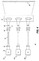
本発明をよりよく理解するために、本発明の装置と方法が使用できる全体的状況を説明することは有益である。図4の概略図は、本発明のいくつかの実施形態で使用される投影装置10の基本構成を示す。3つの光変調組立体40r、40gおよび40bが示され、各光変調組立体は、照明結合器42からの基本的な赤、緑または青(RGB)カラー・バンドのうちの1つをそれぞれ変調する。各光変調組立体40r、40gおよび40bでは、任意選択のレンズ50が、光を光ファイバなどの光ガイド52に導く。光ガイド52の出力で、レンズ54は、光を、ハエの目積分器(fly's eye integrator)や積分バーなどの積分器51内を介して、例えば空間光変調器60まで導くが、空間光変調器60は、DLP、LCOS、その他の変調構成要素でよい。LCOSと共に使用する場合、偏光レーザが使用されるとき、偏光をきわめて偏光された状態に維持することが好ましい。DLP変調器の場合、これは不要である。次に、多数の可能な実施形態により全体が図4に破線で概略的に示された投影光学素子70は、変調光を表示面80に導く。次に、本発明の後の実施形態には、図4に示された全体的な構成が、照明結合器42に使用される様々な構成と共に使用される。照明結合器42は、隣接したスペクトル・バンドの光を交互に提供し、それにより左目と右目の交互のビューが次々と提供される。
In order to better understand the present invention, it is useful to describe the overall situation in which the apparatus and method of the present invention can be used. The schematic of FIG. 4 shows the basic configuration of the
図5は、複数のアレイ44および44’を組み合わせてより大きなアレイを構成するための1つの手法を示す。図6は、図5の構成を斜視図で示す。図5では、追加のアレイ44’の光学軸をアレイ44と一致させるために、1つまたは複数の散在されたミラー46が使用されてもよい。しかしながら、アレイ44をこのように積み重ねることができる数が、熱および間隔要件によって制限される場合があることが分かる。
FIG. 5 illustrates one approach for combining
図5と図6に示した構成は、図7Aと図7Bおよび図8のタイミング図に示したように、異なるスペクトル成分またはずれた隣り合ったスペクトル成分を有する光を使用できるようにある程度修正することができる。図7Aと図7Bは、照明結合器42を示し、図8のタイミング図は、光変調組立体40r、40gおよび40bのいずれかの中で、同じ空間光変調器60(図4)に導かれた光を2つの隣接したカラー・スペクトル間で素早く交番させて、それにより左目画像と右眼画像をどのように提供することができるかを示す。2つのレーザ・バンク44aおよび44bがあり、例として固体レーザ・アレイが示される。レーザ44aおよび44bは、隣接スペクトル・バンドの光を提供する。次に、視聴者は、表示するための単一波長域を分離し選択的に透過し同時に交互の目のための隣接波長域を遮断するフィルタ・メガネを装着する。図8に示したデューティ・サイクルは、それぞれの目に50%照明する。各目上の平均出力密度が同じであれば、デューティ・サイクルをもっと短くすることができる。最適なデューティ・サイクルと頻度率は、空間光変調器の動作速度、レーザ装置の動作速度および視聴者の不快さを最小にする必要性によって選択されなければならない。リフレッシュ・レート120hzの典型的な最小許容周波数が望ましいが、もっと高い周波数が好ましい。三次元DLPデジタル映画用途では、144hzが使用されることが多い。
The configurations shown in FIGS. 5 and 6 are modified to some extent to allow the use of light having different spectral components or shifted adjacent spectral components as shown in the timing diagrams of FIGS. 7A, 7B and 8. be able to. 7A and 7B show the
いくつかの例では、レーザを高品質立体画像化に必要な周波数の変調方式で動作させることが実際的でない場合がある。例えば、レーザをそのような方式で駆動するときにレーザが安定になり、それによりレーザ出力に望ましくないかまたは制御不能な変動が生じる場合がある。本発明の代替実施形態は、固定動作式レーザ(変調されてもよいが、立体的用ではない)を光学シャッタと組み合わせて利用することである。図16と図17は、モータ66によって空間光変調器と同期して回転される光学シャッタ65を示す。図17は、光学シャッタ65が、反射部分75と透過部分76を有することを示す。反射部分75が、44aおよび44bからの光の光経路内に回転されたとき、44aからの光は、投影のための光学システム内に反射され、一方44bからの光は、ビーム・ダンプ67に反射される。同様に、透過部分76が、44aと44bからの光の光経路内に回転されたとき、44bからの光は、投影のために光学システム内に透過され、一方44aからの光はビーム・ダンプに透過される。それにより、部分75と76の回転は、44aと44bからの2つの隣接カラー・バンドを交互にする光学システム照明を提供する。単純化された事例では、44aと44bからの光は、照明源44aからのスペクトルを許容する目のための空間光変調器上の画像セットに対応する時間の50%だけ同時に反射される。44aからの光は、光学シャッタ65で反射され、空間光変調器に送られ、次にスクリーンに投影され、それを、隣接スペクトル44aからの光だけを許容する色選択フィルタ・メガネを装着したユーザが見る。照明源44bからの光は、ビーム・ダンプ67に反射される。同様に、光学シャッタ65は、照明44aと44bの実質的にすべてを時間の50%だけ透過する。この事例では、44aからの光は、ビーム・ダンプ67で終わり、44bからの光は、交互の目のためにコンテンツを画像化する変調器に送られる。この光は、隣接スペクトル44bだけを透過するように設計されたフィルタ・メガネを通して視聴者の対応する目に達する。
In some examples, it may not be practical to operate the laser with the frequency modulation scheme required for high quality stereoscopic imaging. For example, when the laser is driven in such a manner, the laser may become stable, which may cause undesirable or uncontrollable fluctuations in the laser output. An alternative embodiment of the present invention is to utilize a fixed motion laser (which may be modulated but not stereoscopic) in combination with an optical shutter. 16 and 17 show an
この手法は、従来の実施形態より光損失が多いが、先行技術と同じように、実施するのは容易である。先行技術は、適切な隣接スペクトルを分離するために色選択コーティングの使用を必要とする。これは、3つの波長域をすべて同時に処理しなければならない。この実施形態では、光学シャッタの半分(反射部分)に単純なミラーが使用されてもよいが、他方の半分は単純な窓(透過部分)でよい。あるいは、エッジ・フィルタ設計がずれた2つの異なる波長感応コーティングが使用されてもよい。1つのスペクトル・バンドしか必要ないので、専用コーティング・タイプなしに製造する方が実質的に簡単である。いずれの場合も、ゴースト反射が引き起こすクロストーク光が、不適切な隣接スペクトル・バンドから空間光変調器に入るのを防ぐために、基板上に適切な反射防止コーティングが必要な場合がある。さらに、従来の非立体画像の輝度を高めるために、両方の隣接スペクトル・バンドの透過を可能にしたい場合がある。この場合、光学シャッタが除去されてもよく、ダイクロイック・ビームスプリッタが再挿入されてもよい。これは、コンテンツ選択システムによって自動化することができる。 This approach has more light loss than the prior embodiments, but is as easy to implement as the prior art. The prior art requires the use of color selective coatings to separate the appropriate adjacent spectra. This must process all three wavelength bands simultaneously. In this embodiment, a simple mirror may be used for half of the optical shutter (reflection part), but the other half may be a simple window (transmission part). Alternatively, two different wavelength sensitive coatings with shifted edge filter designs may be used. Since only one spectral band is required, it is substantially easier to manufacture without a dedicated coating type. In either case, a suitable anti-reflective coating may be required on the substrate to prevent crosstalk light caused by ghost reflection from entering the spatial light modulator from an inappropriate adjacent spectral band. In addition, it may be desirable to allow transmission of both adjacent spectral bands to increase the brightness of conventional non-stereoscopic images. In this case, the optical shutter may be removed and the dichroic beam splitter may be reinserted. This can be automated by a content selection system.
それぞれの目に必要な色ずれ補正が最小になるよう各レーザのスペクトルの波長が隣接することが望ましく、これと反対に、また、左目と右目の光を十分に分離し、クロストークを最小限に抑えるフィルタを設計できるように十分なスペクトル・シフトを有することが望ましい。そのようなフィルタは、一般に、薄膜式エッジまたは帯域フィルタを利用することによって製造される。そのようなフィルタは、より小さな遷移(より急勾配)で高透過から遮断まで波長が遷移する領域を有し、一般にコストの高い光学層を必要とする。色空間と遷移空間の間のこのトレードオフは、特定の望ましい波長分離を定義する。NESCELレーザは、一般に、同じスペクトル・バンド用に設計された試料間で約0.5nmの変動を有する。したがって、光学コーティングが、完全透過から完全遮断まで1nm以内の遷移領域を有するように十分な許容範囲で設計され製造されれば、最小スペクトル分離は1nmである。しかしながら、より一般に、そのようなコーティングには最小5nmが必要になる。したがって、コーティングの製造コストが限定要因になることが多い。 It is desirable that the wavelength of each laser's spectrum be adjacent so that the color shift correction required for each eye is minimized, and conversely, the left eye and right eye light are well separated to minimize crosstalk. It is desirable to have a sufficient spectral shift so that the filter can be designed to be as low as possible. Such filters are generally manufactured by utilizing thin film edge or bandpass filters. Such a filter has a region where the wavelength transitions from high transmission to cutoff with smaller transitions (steeper) and generally requires an expensive optical layer. This trade-off between color space and transition space defines a particular desirable wavelength separation. NESCEL lasers typically have a variation of about 0.5 nm between samples designed for the same spectral band. Thus, if the optical coating is designed and manufactured with sufficient tolerance to have a transition region within 1 nm from complete transmission to complete cutoff, the minimum spectral separation is 1 nm. More generally, however, such coatings require a minimum of 5 nm. Therefore, the manufacturing cost of the coating is often a limiting factor.
交互の照明サイクルの一方の半分で、図7Aに示したように、アレイ44aが通電される。この光は、ダイクロイック・ビームスプリッタ62から反射する。交互の照明サイクルの他方の半分で、図7Bに示したようにアレイ44bが通電される。この光は、ダイクロイック・ビームスプリッタ62を透過する。非立体的用途では、隣接レーザ44aと44b両方からの光は、より明るい撮像装置を提供するために一緒に使用されてもよく、各レーザ源の寿命を釣り合わせるために半分の電力で使用されてもよい。
In one half of the alternating illumination cycle, the
この構成は、両方の隣接スペクトル・バンドの光を同じ照明軸上にすると有利である。この手法のエタンデュは、前に図5で単一チャネル用に示された構成に示したものと同じままである。したがって、非立体的用途において、両方のスペクトル・バンドが画像化された場合、光源の輝度は実質的に2倍になる。これにより、光学エンジンは、単一光源の低いエタンデュで有効に動作することができ、光学速度が遅くなりコントラストが高くなるという利点が提供される。しかしながら、立体が望ましい場合、ある特定の瞬間に単一の光源だけが利用され、したがって、有効輝度は、図5Bと同じままである。ずらされた隣接スペクトル・バンドが、光源帯域幅全体を大きくし、それにより可能な色域が減少するが、波長をできるだけ近くに維持することによって、この効果は減少する。左目スペクトル・バンドとその後の右目スペクトル・バンドの組み合わせを、それらの白色点ができるだけ近くなるように選択することは望ましい。選択された主要バンド(隣接スペクトル・バンドの組み合わせ)の全体の幅は、従来のキセノン光源の幅よりかなり小さくなければならず、典型的なバンドは、100nmも高くてもよい。レーザを使用する場合、両方の隣接スペクトルを含むバンド全体が、20nm以下しか含むことができず、きわめて単純な光学コーティングを作成するのに十分なマージンが提供され、また色域が従来の照明より実質的に大きくなる。 This configuration is advantageous if light in both adjacent spectral bands is on the same illumination axis. The etendue of this approach remains the same as previously shown in the configuration shown for a single channel in FIG. Thus, in non-stereoscopic applications, when both spectral bands are imaged, the brightness of the light source is substantially doubled. This provides the advantage that the optical engine can operate effectively with a low etendue of a single light source, resulting in slower optical speed and higher contrast. However, if a solid is desired, only a single light source is utilized at any particular moment, so the effective brightness remains the same as in FIG. 5B. The shifted adjacent spectral bands increase the overall light source bandwidth and thereby reduce the possible color gamut, but this effect is reduced by keeping the wavelength as close as possible. It is desirable to select the combination of the left eye spectral band and the subsequent right eye spectral band so that their white points are as close as possible. The overall width of the selected major band (combination of adjacent spectral bands) must be much smaller than that of a conventional xenon light source, and a typical band may be as high as 100 nm. When using a laser, the entire band, including both adjacent spectra, can contain no more than 20 nm, providing sufficient margin to create a very simple optical coating, and the color gamut is more than conventional illumination It becomes substantially larger.
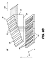
図9aと図9Bはそれぞれ、小さい面積内に集中された4つの固体光アレイ44からのレーザ光を組み合わせる照明結合器42の一実施形態の側面図と斜視図を示す。光方向変更プリズム30が、アレイ44から放射方向D1に放射された光を受け入れる入射面32を有する。光は、光学軸の方向に沿いかつ放射方向D1と実質的に直角の出力方向D2に方向変更される。光方向変更プリズム30は、光方向変更ファセット(facet)38を有する方向変更面36を有する。光方向変更ファセット38は、放射方向D1に対して斜めであり、レーザ26から放射された光を全反射(TIR)する。図9Aと図9Bに示したように互い違いに配列されたとき、これらの特徴形状は、この照明の光経路を狭くして、より狭い光ビームを提供する。図9Bが示すように、光アレイ44は、長手方向Lに延在する複数のレーザ26を有する。方向変更面36上の光方向変更ファセット38と他のファセットも方向Lに延在する。
9a and 9B show a side view and a perspective view, respectively, of one embodiment of an
いくつかの変形が可能である。例えば、図10の側面断面図は、光方向変更プリズム30の光方向変更ファセット38が光アレイ44上の複数列のレーザから同時に光を方向変更するように寸法決めされた代替実施形態を示す。入射面32は、放射方向D1に対して直角でなくてもよく、光アレイ44の配置に対して多少のずれが可能であり、光方向変更プリズム30の屈折率nを考慮する必要がある。
Several variations are possible. For example, the side cross-sectional view of FIG. 10 shows an alternative embodiment in which the
図11の概略ブロック図は、隣接カラー・バンドを使用する実施形態において複数の光方向変更プリズム30を利用して高い輝度を提供することができる方法を示す。図7Aと図7Bに関して前に説明したように、ダイクロイック・ビームスプリッタ62を介した光アレイ44aと44bからの交互の照明は、隣接カラー・バンドの光を空間光変調器60に導いて立体画像を提供する。
The schematic block diagram of FIG. 11 illustrates how multiple
図12の側面断面図は、固体アレイを使用する図9a〜図10に示した実施形態よりさらに小さい構成の照明を提供する、照明結合器42内の光方向変更プリズム30の別の実施形態を示す。この実施形態では、光方向変更プリズム30は、反対の放射方向D1とD1’を有する互いに向かい合うアレイ44からの光を受け入れる2つの方向変更面36を有する。各方向変更面36は、2つのタイプのファセットを有し、それらのファセットは、光方向変更ファセット38と、対応するアレイ44からの入射光に対して垂直であるかまたは垂直に対して斜めの何らかの他の角度でもよい入射ファセット28である。これにより、反射防止コーティング面からのわずかな残余光を各レーザに逆反射させることにより、光方向変更プリズム30に対する種々のレーザ・モジュールの位置合わせが容易になる。この逆反射は、レーザにモード不安定性を引き起こす場合がある複雑な外部空洞を作り出す手段として有用なことがある。そのようなモード・ホッピングは、代表的用途ではノイズと見なされる場合があるが、このノイズは、レーザ・コヒーレンス(および、レーザ間コヒーレンス)をさらに減少させることによって投影の価値を高めることができ、それにより像平面で視覚的斑点が減少する。さらに、この両面手法により、レーザ・モジュールは、互いに隣り合った異なるモジュールからの光で挟まれ、光が光学システムに光学的に組み込まれたときにさらに他の空間混合源を提供する。この場合も、これは、斑点を減少させかつシステム均一性を高めるのに役立つ。この光を光積分器51に直接画像化することができるが、組み合わされた遠視野照明(far field illumination)を変わりに導くことによって、さらなる光積分と斑点減少を実現することができる。この手法により、積分器は、光の複数の点ではなくガウスビーム強度プロファイルを本質的に均一化することが必要になる。近視野照射と遠視野照明の何らかの組み合わせが、照明のエタンデュを最小にしかつ送られた光の均一性を最大にするのに最適な場合がある。さらに、より多くの遠視野照明を利用することにより、照明源と空間光変調エンジンとの間の空間的分離が提供され、したがって熱分離が高められる。
The side cross-sectional view of FIG. 12 shows another embodiment of the
図12に示したレーザ44に対するプリズム30のこの向きが有利であることは分かるが、入力面または出力面に対する垂直入射光は、照明源を組み合わせるためには不要である。しかしながら、面34でプリズム30から出る方向変更された光ビームは、互いに実質的に平行でなければならない。これを実現するには、いくつかの要素を熟慮する必要がある。そのような要素には、各面の入力ファセットに対する各面(異なる場合があるので)のレーザ44の入射角と、材料の屈折率に基づくプリズム内の屈折率との組み合わせがある。更に、各面から方向変更ファセット(この場合も、これらは各面で異なる場合がある)の反射を考慮しなければならず、プリズムの屈折率との組み合わせが、出口面からの出力光ビームが平行になるように協力しなければならない。
While this orientation of the
図14の概略ブロック図は、図13に関して述べた基本構成による各色チャネル内で光方向変更プリズム30を使用するプロジェクタ装置10の一実施形態を示す。光変調組立体40r、40gおよび40bはそれぞれ、ダイクロイック・ビーム62で構成された1対の光方向変更プリズム30を有する。各光変調組立体において、いずれかの光方向変更プリズム30からの隣接スペクトル・バンド光は、光ガイド52を通ってレンズ50と積分器51までダイクロイック・ビームスプリッタ62を介して導かれる。空間光変調器60は、デジタル・マイクロミラー、LCOS、光を変調する他の装置である。示された実施形態は、マイクロミラー装置の角度変調を使用するように設計されているが、LCOSと供に利用されてもよく、薄膜被覆面68は、入射光をその反射角に従って反射または透過するように処理され、その結果、変調光がダイクロイック結合器82に導かれる。ダイクロイック結合器82は、光を波長に従って選択的に反射または透過するダイクロイック面84の構成を有し、各光変調組立体40r、40gおよび40bからの変調光を投影光学素子70を介して単一光経路上に結合する。光変調組立体40r、40gおよび40bは、デュアル隣接スペクトル・バンドから成り、ダイクロイック面84は、これらの隣接バンドを両方とも同様に処理するように設計される。
The schematic block diagram of FIG. 14 shows an embodiment of the
図15の概略ブロック図は、図14と類似しているが光ガイド52のない一実施形態のプロジェクタ装置10の代替実施形態を示す。この実施形態は、光ガイド52が透過光の偏光を劣化させる傾向があるので有利なことがある。そのような実施形態では、偏光状態が維持されるので、小型レンズ・アレイは、照明を均一にするのに優れた効果を発揮する。
The schematic block diagram of FIG. 15 shows an alternative embodiment of the
本発明は、本明細書で説明された例示的な実施形態からいくつかの変形が可能である。例えば、VECSELや他のレーザ・アレイの代替として様々なレーザ光源を使用することができる。光方向変更プリズム30は、多くのきわめて透過性の高い材料から作成することができる。低出力用途では、プラスチックが選択されてもよく、部品にほとんど応力をかけないモールド成形工程が使用される。同様に、生じる応力または熱誘導複屈折が最小である材料が選択されることが望ましい。そのような材料の例は、アクリルやZeon ChemicalsからのZeonexなどのプラスチックである。これは、特に、光方向変更プリズム30が偏光式光学システムで使用される場合に重要である。
The present invention is capable of several variations from the exemplary embodiments described herein. For example, various laser light sources can be used as an alternative to VECSEL or other laser arrays. The
多数の高出力レーザが必要とされるデジタル映画などのより高出力の用途では、さらにわずかなレベルの光吸収により蓄積した熱が、最終的に材料を劣化させ透過率を低下させる可能性があるので、プラスチックは、光方向変更プリズム30と供に使用するには現実的でない場合がある。この場合、ガラスが好ましい。この場合も、応力複屈折が、偏光式プロジェクタの問題になる可能性がある。この場合、SF57などの複屈折応力係数の小さいガラスを使用することができる。
In higher power applications such as digital movies where a large number of high power lasers are required, the heat stored by even a slight level of light absorption can eventually degrade the material and reduce transmission. As such, plastic may not be practical for use with the
別の選択肢は、材料の加熱を防ぎ、これにより複屈折が生じないようにするために、石英ガラスなどのきわめて吸収率の低い光学ガラスを使用することである。そのようなタイプの材料は、モールド成形ガラス部品を作成するのに役立たない場合があり、したがって、完全なプリズムを作成するために複数部品の従来の研磨および/または組み立てが必要になる。モールド成形が望ましい場合は、低速モールド工程が好ましく、また固有応力を減少させるためにアニール処理が望ましい。残留複屈折から生じる可能性のある回転偏光状態を除去するために、クリーンアップ偏光子が望ましいかまたは必要な場合がある。これは、主に、効率、部品コストおよび必要な偏光純度のトレードオフである。 Another option is to use an optical glass with very low absorptance, such as quartz glass, to prevent the material from heating and thereby avoiding birefringence. Such types of materials may not be useful for making molded glass parts, and thus require multiple parts conventional polishing and / or assembly to create a complete prism. When molding is desired, a low speed molding process is preferred, and an annealing treatment is desirable to reduce intrinsic stress. A clean-up polarizer may be desirable or necessary to remove rotational polarization states that may result from residual birefringence. This is mainly a trade-off between efficiency, component cost and required polarization purity.
本発明の実施形態は、光源の縦横比を、使用される空間光変調器の縦横比に適するように形成するのに役立つ。本発明の実施形態は、光ガイドが柔軟であるだけでなく、実質的に変調器と同じ縦横比で形成することもできるように、様々な寸法の光ガイド52と共に使用することができる。デジタル映画の場合、この比率は、約1.9:1である。代替実施形態は、方形コア・ファイバを使用することができる。同様に、共通多モード光ファイバなどの円形コア光導波路を利用することができる。
Embodiments of the present invention help to form the light source in an aspect ratio that is suitable for the aspect ratio of the spatial light modulator used. Embodiments of the present invention can be used with
いくつかの実施形態に関して、照明結合器42と積分器51間の光導波路が示されているが、投影光学エンジンからの照明源を中継し分離する他の方法が可能であることは一般に知られている。図15に示されたような共通レンズとの中継は、所望の温度と空間分離を達成する1つの手法である。
For some embodiments, an optical waveguide between
本発明は、特にいくつかの好ましい実施形態を参照して詳細に説明されたが、本発明の趣旨および範疇で変形および修正を行うことができることを理解されよう。例えば、詳細な実施形態においてレーザ・アレイが示された場合、代替として他の固体放射部品を使用することができる。各光経路に支持レンズを追加してもよい。本明細書に示された光学組立体では、均一化または光積分および中継の順序は、実際に大きな違いなしに逆にすることができる。 Although the invention has been described in detail with particular reference to certain preferred embodiments, it will be understood that variations and modifications can be effected within the spirit and scope of the invention. For example, if a laser array is shown in the detailed embodiment, other solid state radiating components can be used instead. A support lens may be added to each light path. In the optical assembly shown herein, the order of homogenization or light integration and relaying can actually be reversed without significant differences.
したがって、個別に制御された隣接スペクトル・バンド照明源を使用して輝度または立体的デジタル映画投影を強化する装置および方法が提供される。 Accordingly, an apparatus and method is provided for enhancing luminance or stereoscopic digital movie projection using individually controlled adjacent spectral band illumination sources.
10 プロジェクタ装置、12 光源、14 プリズム組立体、16 位置、18 光学素子、20,20r,20g,20b 空間光変調器、26 レーザ、28 入射ファセット、30 光方向変更プリズム、32 入射面、34 出力面、36 方向変更面
、38 光方向変更ファセット、40r,40g,40b 光変調組立体、42 照明結合器、44,44’,44a,44b 固体光アレイ、46 ミラー、48,56 偏光ビームスプリッタ、50 レンズ、51 積分器、52 光ガイド、54 レンズ、60 空間光変調器、62 ダイクロイック・ビームスプリッタ、65 回転円板光学シャッタ、66 モータ、67 ビーム・ダンプ、68 ダイクロイック面、70 投影光学、74 マイクロミラー、80 表示面、82 ダイクロイック結合器、84 ダイクロイック面、A 軸、D1,D1’ 放射方向、D2 出力方向。
DESCRIPTION OF
Claims (5)
(b)前記光源からの光を単一空間領域に結合するダイクロイック・ビームスプリッタと、
(c)それぞれスペクトル的に隣接した光源からの照明光を交互に提供するコントローラ・システムと、
(d)前記コントローラ・システムによって交互に提供された各照明光を受け取り、前記交互に提供された各照明光に対応する画像化光を提供する空間光変調器と、
(e)前記空間光変調器からの画像化光を投影領域に出力するための投影光学素子と、
(f)1つの隣接スペクトル・バンド状態をそれぞれの目に選択的に透過し、同時に別の隣接スペクトル・バンドを拒否するための視聴者用のフィルタ・メガネと、
を含む、立体的デジタル画像プロジェクタ。 It is controlled separately (a), a two light sources adjacent spectrally has a spectral band adjacent spectrally, both spectral band of the red spectrum, the green spectrum, or blue spectrum Two light sources corresponding to either
(B) a dichroic beam splitter for combining light from the light source into a single spatial region;
(C) a controller system that provides mutually exchange the illumination light from the spectrally adjacent light sources, respectively,
And (d) the will receive the respective illumination light provided alternately by the controller system, the spatial light modulator to provide an imaging light corresponding to each illumination light provided to the alternate,
(E) a projection optical element for outputting imaging light from the spatial light modulator to a projection region;
(F) filter glasses for viewers to selectively transmit one adjacent spectral band state to each eye and simultaneously reject another adjacent spectral band ;
A three-dimensional digital image projector.
The digital image projector of claim 4, wherein polarization is maintained from the light source to the spatial light modulator.
Applications Claiming Priority (3)
| Application Number | Priority Date | Filing Date | Title |
|---|---|---|---|
| US11/956,666 US20090153752A1 (en) | 2007-12-14 | 2007-12-14 | Projector using independent multiple wavelength light sources |
| US11/956,666 | 2007-12-14 | ||
| PCT/US2008/013610 WO2009078941A1 (en) | 2007-12-14 | 2008-12-11 | Projector using independent multiple wavelength light sources |
Publications (3)
| Publication Number | Publication Date |
|---|---|
| JP2011510333A JP2011510333A (en) | 2011-03-31 |
| JP2011510333A5 JP2011510333A5 (en) | 2012-02-02 |
| JP5416129B2 true JP5416129B2 (en) | 2014-02-12 |
Family
ID=40429967
Family Applications (1)
| Application Number | Title | Priority Date | Filing Date |
|---|---|---|---|
| JP2010537960A Expired - Fee Related JP5416129B2 (en) | 2007-12-14 | 2008-12-11 | 3D digital image projector |
Country Status (8)
| Country | Link |
|---|---|
| US (1) | US20090153752A1 (en) |
| EP (1) | EP2220533B1 (en) |
| JP (1) | JP5416129B2 (en) |
| CN (1) | CN101889233B (en) |
| AT (1) | ATE534931T1 (en) |
| CA (1) | CA2703860A1 (en) |
| TW (1) | TWI439733B (en) |
| WO (1) | WO2009078941A1 (en) |
Families Citing this family (87)
| Publication number | Priority date | Publication date | Assignee | Title |
|---|---|---|---|---|
| US7871165B2 (en) * | 2007-11-30 | 2011-01-18 | Eastman Kodak Company | Stereo projection apparatus using polarized solid state light sources |
| US7891816B2 (en) * | 2008-02-25 | 2011-02-22 | Eastman Kodak Company | Stereo projection using polarized solid state light sources |
| US20090309127A1 (en) * | 2008-06-13 | 2009-12-17 | Soraa, Inc. | Selective area epitaxy growth method and structure |
| US8847249B2 (en) | 2008-06-16 | 2014-09-30 | Soraa, Inc. | Solid-state optical device having enhanced indium content in active regions |
| US7926951B2 (en) * | 2008-07-11 | 2011-04-19 | Eastman Kodak Company | Laser illuminated micro-mirror projector |
| US8767787B1 (en) | 2008-07-14 | 2014-07-01 | Soraa Laser Diode, Inc. | Integrated laser diodes with quality facets on GaN substrates |
| US8805134B1 (en) | 2012-02-17 | 2014-08-12 | Soraa Laser Diode, Inc. | Methods and apparatus for photonic integration in non-polar and semi-polar oriented wave-guided optical devices |
| US8143148B1 (en) | 2008-07-14 | 2012-03-27 | Soraa, Inc. | Self-aligned multi-dielectric-layer lift off process for laser diode stripes |
| US8284810B1 (en) | 2008-08-04 | 2012-10-09 | Soraa, Inc. | Solid state laser device using a selected crystal orientation in non-polar or semi-polar GaN containing materials and methods |
| WO2010017148A1 (en) | 2008-08-04 | 2010-02-11 | Soraa, Inc. | White light devices using non-polar or semipolar gallium containing materials and phosphors |
| DE112010001615T5 (en) * | 2009-04-13 | 2012-08-02 | Soraa, Inc. | Structure of an optical element using GaN substrates for laser applications |
| US8634442B1 (en) | 2009-04-13 | 2014-01-21 | Soraa Laser Diode, Inc. | Optical device structure using GaN substrates for laser applications |
| US8837545B2 (en) | 2009-04-13 | 2014-09-16 | Soraa Laser Diode, Inc. | Optical device structure using GaN substrates and growth structures for laser applications |
| US9829780B2 (en) * | 2009-05-29 | 2017-11-28 | Soraa Laser Diode, Inc. | Laser light source for a vehicle |
| US9800017B1 (en) | 2009-05-29 | 2017-10-24 | Soraa Laser Diode, Inc. | Laser device and method for a vehicle |
| US8509275B1 (en) | 2009-05-29 | 2013-08-13 | Soraa, Inc. | Gallium nitride based laser dazzling device and method |
| US10108079B2 (en) * | 2009-05-29 | 2018-10-23 | Soraa Laser Diode, Inc. | Laser light source for a vehicle |
| US8247887B1 (en) | 2009-05-29 | 2012-08-21 | Soraa, Inc. | Method and surface morphology of non-polar gallium nitride containing substrates |
| US9250044B1 (en) | 2009-05-29 | 2016-02-02 | Soraa Laser Diode, Inc. | Gallium and nitrogen containing laser diode dazzling devices and methods of use |
| US8427590B2 (en) * | 2009-05-29 | 2013-04-23 | Soraa, Inc. | Laser based display method and system |
| US8851684B2 (en) * | 2009-06-18 | 2014-10-07 | Nec Display Solutions, Ltd. | Optical unit including an integrator optical system, and projection display device including the optical unit |
| US8142021B2 (en) * | 2009-06-25 | 2012-03-27 | Eastman Kodak Company | Dump path light intensity sensing in light projector |
| US8220938B2 (en) * | 2009-06-25 | 2012-07-17 | Eastman Kodak Company | Image path light intensity sensing during a blanking period between a left-eye light beam and a right-eye light beam in a stereoscopic light projector |
| US8237777B2 (en) * | 2009-06-25 | 2012-08-07 | Eastman Kodak Company | Stereoscopic image intensity balancing in light projector |
| US20100328611A1 (en) * | 2009-06-25 | 2010-12-30 | Silverstein Barry D | Leakage light intensity sensing in light projector |
| US8162483B2 (en) * | 2009-06-25 | 2012-04-24 | Eastman Kodak Company | Hierarchical light intensity control in light projector |
| US8066382B2 (en) * | 2009-07-14 | 2011-11-29 | Eastman Kodak Company | Stereoscopic projector with rotating segmented disk |
| JP2011043703A (en) * | 2009-08-21 | 2011-03-03 | Victor Co Of Japan Ltd | Illuminator and projection type image display device using the illuminator |
| US8355418B2 (en) * | 2009-09-17 | 2013-01-15 | Soraa, Inc. | Growth structures and method for forming laser diodes on {20-21} or off cut gallium and nitrogen containing substrates |
| US8750342B1 (en) | 2011-09-09 | 2014-06-10 | Soraa Laser Diode, Inc. | Laser diodes with scribe structures |
| US20110102563A1 (en) * | 2009-11-03 | 2011-05-05 | Johnson Jr Robert L | Multi-spectral stereographic display system |
| US20110102562A1 (en) * | 2009-11-03 | 2011-05-05 | PV Omega, LLC | Multi-spectral stereographic display system with additive and subtractive techniques |
| US8320621B2 (en) | 2009-12-21 | 2012-11-27 | Microsoft Corporation | Depth projector system with integrated VCSEL array |
| US8444272B2 (en) * | 2010-01-25 | 2013-05-21 | Corning Incorporated | Multi-projector system using multiplexed illumination |
| US10147850B1 (en) | 2010-02-03 | 2018-12-04 | Soraa, Inc. | System and method for providing color light sources in proximity to predetermined wavelength conversion structures |
| US8905588B2 (en) | 2010-02-03 | 2014-12-09 | Sorra, Inc. | System and method for providing color light sources in proximity to predetermined wavelength conversion structures |
| US8451876B1 (en) | 2010-05-17 | 2013-05-28 | Soraa, Inc. | Method and system for providing bidirectional light sources with broad spectrum |
| US8670029B2 (en) | 2010-06-16 | 2014-03-11 | Microsoft Corporation | Depth camera illuminator with superluminescent light-emitting diode |
| US8816319B1 (en) | 2010-11-05 | 2014-08-26 | Soraa Laser Diode, Inc. | Method of strain engineering and related optical device using a gallium and nitrogen containing active region |
| US9048170B2 (en) | 2010-11-09 | 2015-06-02 | Soraa Laser Diode, Inc. | Method of fabricating optical devices using laser treatment |
| US9025635B2 (en) | 2011-01-24 | 2015-05-05 | Soraa Laser Diode, Inc. | Laser package having multiple emitters configured on a support member |
| US9595813B2 (en) | 2011-01-24 | 2017-03-14 | Soraa Laser Diode, Inc. | Laser package having multiple emitters configured on a substrate member |
| US9093820B1 (en) | 2011-01-25 | 2015-07-28 | Soraa Laser Diode, Inc. | Method and structure for laser devices using optical blocking regions |
| US9236530B2 (en) | 2011-04-01 | 2016-01-12 | Soraa, Inc. | Miscut bulk substrates |
| US9287684B2 (en) | 2011-04-04 | 2016-03-15 | Soraa Laser Diode, Inc. | Laser package having multiple emitters with color wheel |
| US9325976B2 (en) | 2011-05-02 | 2016-04-26 | Dolby Laboratories Licensing Corporation | Displays, including HDR and 3D, using bandpass filters and other techniques |
| WO2012156519A1 (en) | 2011-05-17 | 2012-11-22 | Lumatec Gesellschaft für medizinisch-technische Geräte mbH | Lighting apparatus, and lighting device, optical projector, and headlamp each having at least one such lighting apparatus |
| US9646827B1 (en) | 2011-08-23 | 2017-05-09 | Soraa, Inc. | Method for smoothing surface of a substrate containing gallium and nitrogen |
| US8651663B2 (en) | 2011-10-03 | 2014-02-18 | Eastman Kodak Company | Stereoscopic projector using scrolling color bands |
| US8746888B2 (en) | 2011-10-03 | 2014-06-10 | Eastman Kodak Company | Stereoscopic projector using spectrally-adjacent color bands |
| US8971370B1 (en) | 2011-10-13 | 2015-03-03 | Soraa Laser Diode, Inc. | Laser devices using a semipolar plane |
| CN102402005B (en) * | 2011-12-06 | 2015-11-25 | 北京理工大学 | Bifocal-surface monocular stereo helmet-mounted display device with free-form surfaces |
| CN103207509B (en) * | 2012-01-12 | 2015-06-24 | 三菱电机株式会社 | Light Source Device And Projecting Display Device |
| US8864314B2 (en) | 2012-01-17 | 2014-10-21 | Eastman Kodak Company | Stereoscopic projection system using tunable light emitters |
| US20130182321A1 (en) | 2012-01-17 | 2013-07-18 | Barry David Silverstein | Filter glasses for spectral stereoscopic projection system |
| US10768449B2 (en) | 2012-01-17 | 2020-09-08 | Imax Theatres International Limited | Stereoscopic glasses using tilted filters |
| US8947424B2 (en) | 2012-01-17 | 2015-02-03 | Eastman Kodak Company | Spectral stereoscopic projection system |
| US9335541B2 (en) | 2012-01-17 | 2016-05-10 | Imax Theatres International Limited | Stereoscopic glasses using dichroic and absorptive layers |
| US9020003B1 (en) | 2012-03-14 | 2015-04-28 | Soraa Laser Diode, Inc. | Group III-nitride laser diode grown on a semi-polar orientation of gallium and nitrogen containing substrates |
| JP2013197033A (en) * | 2012-03-22 | 2013-09-30 | Harison Toshiba Lighting Corp | Solid lighting device |
| US9343871B1 (en) | 2012-04-05 | 2016-05-17 | Soraa Laser Diode, Inc. | Facet on a gallium and nitrogen containing laser diode |
| US9800016B1 (en) | 2012-04-05 | 2017-10-24 | Soraa Laser Diode, Inc. | Facet on a gallium and nitrogen containing laser diode |
| US10559939B1 (en) | 2012-04-05 | 2020-02-11 | Soraa Laser Diode, Inc. | Facet on a gallium and nitrogen containing laser diode |
| CN104272728B (en) | 2012-04-13 | 2017-12-01 | Red.Com有限责任公司 | Video projectors' system |
| US8998447B2 (en) * | 2012-09-26 | 2015-04-07 | Projectdesign As | Illumination devices using array of reflectors |
| WO2014102976A1 (en) | 2012-12-27 | 2014-07-03 | Necディスプレイソリューションズ株式会社 | Projector and method for controlling same |
| KR102135345B1 (en) * | 2013-01-22 | 2020-07-17 | 엘지전자 주식회사 | Image projection apparatus |
| CN104937487B (en) | 2013-01-23 | 2017-04-19 | 三菱电机株式会社 | Projection-type display device |
| US10237523B2 (en) * | 2013-05-07 | 2019-03-19 | Dolby Laboratories Licensing Corporation | Digital point spread function (DPSF) and dual modulation projection (including lasers) using DPSF |
| JP6008810B2 (en) * | 2013-09-05 | 2016-10-19 | ウシオ電機株式会社 | Laser light source device |
| US9329461B2 (en) | 2013-10-28 | 2016-05-03 | Dell Products, Lp | Hybrid light engine for projector |
| TWI526771B (en) | 2014-07-04 | 2016-03-21 | 台達電子工業股份有限公司 | Light source system |
| US9246311B1 (en) | 2014-11-06 | 2016-01-26 | Soraa Laser Diode, Inc. | Method of manufacture for an ultraviolet laser diode |
| CN107111216B (en) | 2014-12-31 | 2021-02-26 | 杜比实验室特许公司 | High contrast discrete input prism for image projector |
| JP6508466B2 (en) * | 2015-05-29 | 2019-05-08 | セイコーエプソン株式会社 | Light source device and projector |
| CA2936725C (en) * | 2015-07-21 | 2022-04-26 | Queen's University At Kingston | Multiplexed excitation emission matrix spectroscopy |
| CN107925750B (en) * | 2015-08-28 | 2019-06-14 | 富士胶片株式会社 | Projection arrangement with range image acquisition device and projection mapping method |
| US9787963B2 (en) | 2015-10-08 | 2017-10-10 | Soraa Laser Diode, Inc. | Laser lighting having selective resolution |
| CN107463057A (en) * | 2016-06-02 | 2017-12-12 | 中强光电股份有限公司 | Optical projection system and illuminator |
| EP4120678A1 (en) | 2016-09-30 | 2023-01-18 | Dolby Laboratories Licensing Corporation | Beam combining for highlight projection |
| KR102626294B1 (en) | 2017-05-11 | 2024-01-17 | 쇠라 테크널러지스 인코포레이티드 | Switchyard beam routing of patterned light for additive manufacturing |
| US10771155B2 (en) | 2017-09-28 | 2020-09-08 | Soraa Laser Diode, Inc. | Intelligent visible light with a gallium and nitrogen containing laser source |
| US10222474B1 (en) | 2017-12-13 | 2019-03-05 | Soraa Laser Diode, Inc. | Lidar systems including a gallium and nitrogen containing laser light source |
| US10551728B1 (en) | 2018-04-10 | 2020-02-04 | Soraa Laser Diode, Inc. | Structured phosphors for dynamic lighting |
| US11239637B2 (en) | 2018-12-21 | 2022-02-01 | Kyocera Sld Laser, Inc. | Fiber delivered laser induced white light system |
| US11421843B2 (en) | 2018-12-21 | 2022-08-23 | Kyocera Sld Laser, Inc. | Fiber-delivered laser-induced dynamic light system |
| US11884202B2 (en) | 2019-01-18 | 2024-01-30 | Kyocera Sld Laser, Inc. | Laser-based fiber-coupled white light system |
Family Cites Families (49)
| Publication number | Priority date | Publication date | Assignee | Title |
|---|---|---|---|---|
| US4441791A (en) * | 1980-09-02 | 1984-04-10 | Texas Instruments Incorporated | Deformable mirror light modulator |
| JPH01116521A (en) * | 1987-10-29 | 1989-05-09 | Furotsugusu:Kk | Colored stereoscopic vision method |
| JPH0278393A (en) * | 1988-09-14 | 1990-03-19 | Hitachi Ltd | Stereoscopic color picture display device |
| US5083857A (en) * | 1990-06-29 | 1992-01-28 | Texas Instruments Incorporated | Multi-level deformable mirror device |
| US5704700A (en) * | 1994-07-25 | 1998-01-06 | Proxima Corporation | Laser illuminated image projection system and method of using same |
| US5537476A (en) * | 1994-11-21 | 1996-07-16 | International Business Machines Corporation | Secure viewing of display units by image superposition and wavelength separation |
| EP0722253A3 (en) * | 1995-01-10 | 1996-10-30 | Ibm | Arrangements for projection displays employing reflective light valves |
| US5808795A (en) * | 1995-03-06 | 1998-09-15 | Nikon Corporation | Projection type display apparatus |
| US6062694A (en) * | 1995-03-06 | 2000-05-16 | Nikon Corporation | Projection type display apparatus |
| US5719695A (en) * | 1995-03-31 | 1998-02-17 | Texas Instruments Incorporated | Spatial light modulator with superstructure light shield |
| US5535047A (en) * | 1995-04-18 | 1996-07-09 | Texas Instruments Incorporated | Active yoke hidden hinge digital micromirror device |
| JPH09159988A (en) * | 1995-12-12 | 1997-06-20 | Nikon Corp | Projection type display device |
| JP3738505B2 (en) * | 1996-05-10 | 2006-01-25 | 株式会社ニコン | Projection display |
| JP3557317B2 (en) * | 1996-09-02 | 2004-08-25 | テキサス インスツルメンツ インコーポレイテツド | Projector device and color separation / synthesis device |
| US5914818A (en) * | 1996-11-29 | 1999-06-22 | Texas Instruments Incorporated | Offset projection lens for use with reflective spatial light modulators |
| US6008951A (en) * | 1996-12-31 | 1999-12-28 | Texas Instruments Incorporated | Offset projection zoom lens with fixed rear group for reflective spatial light modulators |
| WO1998049837A1 (en) * | 1997-04-30 | 1998-11-05 | Ldt Gmbh & Co. Laser-Display-Technologie Kg | Method and facility for light-beam projection of images on a screen |
| US6215464B1 (en) * | 1997-06-10 | 2001-04-10 | Jorgen Korsgaard Jensen | Stereoscopic intersecting beam phosphorous display system |
| US5907437A (en) * | 1997-07-10 | 1999-05-25 | Hughes-Jvc Technology Corporation | Converging optics for a single light valve full-color projector |
| US6240116B1 (en) * | 1997-08-14 | 2001-05-29 | Sdl, Inc. | Laser diode array assemblies with optimized brightness conservation |
| US5930050A (en) * | 1997-10-21 | 1999-07-27 | Texas Instruments Incorporated | Anamorphic lens for providing wide-screen images generated by a spatial light modulator |
| US6010121A (en) * | 1999-04-21 | 2000-01-04 | Lee; Chi Ping | Work piece clamping device of workbench |
| DE19924167B4 (en) * | 1999-05-26 | 2006-05-24 | Daimlerchrysler Ag | Apparatus for reproducing color images |
| DE10005335C2 (en) * | 2000-02-08 | 2002-06-27 | Daimler Chrysler Ag | Method and device for multi-dimensional representation of an object |
| US6501773B1 (en) * | 2000-06-19 | 2002-12-31 | Versatile Optical Networks, Inc. | Stabilization of a laser array module |
| US7102700B1 (en) * | 2000-09-02 | 2006-09-05 | Magic Lantern Llc | Laser projection system |
| US6547396B1 (en) * | 2001-12-27 | 2003-04-15 | Infocus Corporation | Stereographic projection system |
| JP2003186112A (en) * | 2001-12-19 | 2003-07-03 | Olympus Optical Co Ltd | Image projection and display device |
| US7520624B2 (en) * | 2001-12-21 | 2009-04-21 | Bose Corporation | Light enhancing |
| JP4503910B2 (en) * | 2002-03-08 | 2010-07-14 | オリンパス株式会社 | Image display method, image display apparatus, and image printing apparatus |
| US6802613B2 (en) * | 2002-10-16 | 2004-10-12 | Eastman Kodak Company | Broad gamut color display apparatus using an electromechanical grating device |
| US7052145B2 (en) * | 2003-02-28 | 2006-05-30 | Florida Atlantic University | Displays using solid state light sources |
| US6950454B2 (en) * | 2003-03-24 | 2005-09-27 | Eastman Kodak Company | Electronic imaging system using organic laser array illuminating an area light valve |
| JP2004333561A (en) * | 2003-04-30 | 2004-11-25 | Nippon Hoso Kyokai <Nhk> | Stereoscopic image display device |
| DE602004026791D1 (en) * | 2003-10-21 | 2010-06-02 | Barco Nv | Method and device for carrying out a stereoscopic image display on the basis of color-selective filters |
| US8587849B2 (en) * | 2004-04-05 | 2013-11-19 | Hewlett-Packard Development Company, L.P. | Imaging systems, imaging device analysis systems, imaging device analysis methods, and light beam emission methods |
| KR20070046831A (en) * | 2004-07-30 | 2007-05-03 | 노바룩스 인코포레이티드 | Projection display apparatus, system, and method |
| JP2006337609A (en) * | 2005-05-31 | 2006-12-14 | Sanyo Electric Co Ltd | Lighting system and projection type video display apparatus |
| US20060280209A1 (en) * | 2005-02-11 | 2006-12-14 | Hans-Georg Treusch | Beam combining methods and devices with high output intensity |
| JP2006349731A (en) * | 2005-06-13 | 2006-12-28 | Olympus Corp | Image projector |
| US20070024959A1 (en) * | 2005-07-26 | 2007-02-01 | Infocus Corporation | Laser combiner |
| US7988688B2 (en) * | 2006-09-21 | 2011-08-02 | Lockheed Martin Corporation | Miniature apparatus and method for optical stimulation of nerves and other animal tissue |
| EP2597517A2 (en) * | 2005-11-08 | 2013-05-29 | Garrett J Young | Apparatus, methods, and systems for multi-primary display or projection |
| US7528906B2 (en) * | 2006-01-23 | 2009-05-05 | Real D | Achromatic polarization switches |
| WO2007127269A2 (en) * | 2006-04-25 | 2007-11-08 | Corporation For Laser Optics Research | 3-d projection full color multimedia display |
| US7690794B2 (en) * | 2006-07-02 | 2010-04-06 | Simon Andrew Boothroyd | Image-combining device and projection display apparatus having image-combining devices incorporated therein |
| US8427394B2 (en) * | 2006-11-30 | 2013-04-23 | Reald Inc. | Shutter glass drive scheme for sequential-color displays |
| US8388138B1 (en) * | 2007-03-11 | 2013-03-05 | Simon Boothroyd | Projection display systems |
| US8107035B2 (en) * | 2007-04-19 | 2012-01-31 | Necsel Intellectual Property | Laser backlighting for displays |
-
2007
- 2007-12-14 US US11/956,666 patent/US20090153752A1/en not_active Abandoned
-
2008
- 2008-12-11 AT AT08861927T patent/ATE534931T1/en active
- 2008-12-11 JP JP2010537960A patent/JP5416129B2/en not_active Expired - Fee Related
- 2008-12-11 EP EP08861927A patent/EP2220533B1/en active Active
- 2008-12-11 WO PCT/US2008/013610 patent/WO2009078941A1/en active Application Filing
- 2008-12-11 CA CA2703860A patent/CA2703860A1/en not_active Abandoned
- 2008-12-11 CN CN2008801192853A patent/CN101889233B/en not_active Expired - Fee Related
- 2008-12-12 TW TW097148602A patent/TWI439733B/en active
Also Published As
| Publication number | Publication date |
|---|---|
| EP2220533B1 (en) | 2011-11-23 |
| TWI439733B (en) | 2014-06-01 |
| JP2011510333A (en) | 2011-03-31 |
| WO2009078941A1 (en) | 2009-06-25 |
| TW200931067A (en) | 2009-07-16 |
| ATE534931T1 (en) | 2011-12-15 |
| CA2703860A1 (en) | 2009-06-25 |
| EP2220533A1 (en) | 2010-08-25 |
| CN101889233A (en) | 2010-11-17 |
| US20090153752A1 (en) | 2009-06-18 |
| CN101889233B (en) | 2012-07-04 |
Similar Documents
| Publication | Publication Date | Title |
|---|---|---|
| JP5416129B2 (en) | 3D digital image projector | |
| TWI450017B (en) | Stereo projection apparatus using polarized solid state light sources | |
| JP5575894B2 (en) | Stereoscopic image projector with rotating multi-part disk | |
| CN102474630B (en) | Etendue reduced stereo projection using segmented disk | |
| JP5323864B2 (en) | Stereoscopic projection with a solid state polarization source | |
| TWI444748B (en) | Laser projection using spatial and temporal mixing | |
| JP5964436B2 (en) | Stereo projector using spectrally adjacent color bands | |
| JP2011527766A (en) | Laser illuminated micro mirror projector | |
| US9466941B2 (en) | Patterned retarder and optical engine for laser projection apparatus | |
| US20110261174A1 (en) | Stereoscopic digital projection apparatus using polarized light |
Legal Events
| Date | Code | Title | Description |
|---|---|---|---|
| A521 | Request for written amendment filed |
Free format text: JAPANESE INTERMEDIATE CODE: A523 Effective date: 20111207 |
|
| A621 | Written request for application examination |
Free format text: JAPANESE INTERMEDIATE CODE: A621 Effective date: 20111207 |
|
| A521 | Request for written amendment filed |
Free format text: JAPANESE INTERMEDIATE CODE: A523 Effective date: 20121203 |
|
| A977 | Report on retrieval |
Free format text: JAPANESE INTERMEDIATE CODE: A971007 Effective date: 20130425 |
|
| A131 | Notification of reasons for refusal |
Free format text: JAPANESE INTERMEDIATE CODE: A131 Effective date: 20130507 |
|
| A521 | Request for written amendment filed |
Free format text: JAPANESE INTERMEDIATE CODE: A523 Effective date: 20130805 |
|
| A61 | First payment of annual fees (during grant procedure) |
Free format text: JAPANESE INTERMEDIATE CODE: A61 Effective date: 20131114 |
|
| S111 | Request for change of ownership or part of ownership |
Free format text: JAPANESE INTERMEDIATE CODE: R313113 |
|
| R350 | Written notification of registration of transfer |
Free format text: JAPANESE INTERMEDIATE CODE: R350 |
|
| S111 | Request for change of ownership or part of ownership |
Free format text: JAPANESE INTERMEDIATE CODE: R313113 |
|
| R350 | Written notification of registration of transfer |
Free format text: JAPANESE INTERMEDIATE CODE: R350 |
|
| LAPS | Cancellation because of no payment of annual fees |