JP2006337609A - Lighting system and projection type video display apparatus - Google Patents
Lighting system and projection type video display apparatus Download PDFInfo
- Publication number
- JP2006337609A JP2006337609A JP2005160687A JP2005160687A JP2006337609A JP 2006337609 A JP2006337609 A JP 2006337609A JP 2005160687 A JP2005160687 A JP 2005160687A JP 2005160687 A JP2005160687 A JP 2005160687A JP 2006337609 A JP2006337609 A JP 2006337609A
- Authority
- JP
- Japan
- Prior art keywords
- light
- light source
- color
- source unit
- polarization
- Prior art date
- Legal status (The legal status is an assumption and is not a legal conclusion. Google has not performed a legal analysis and makes no representation as to the accuracy of the status listed.)
- Pending
Links
Images


Abstract
Description
この発明は、照明装置、投写型映像表示装置に関する。 The present invention relates to an illumination device and a projection display apparatus.
液晶プロジェクタなどに用いられる照明装置としては、超高圧水銀ランプ、メタルハライドランプ、キセノンランプ等のランプと、その照射光を平行光化するパラボラリフレクタから成るものが一般的である。更に、近年においては、発光ダイオード(LED)を光源として用いることも試みられている(特許文献1参照)。 As an illuminating device used for a liquid crystal projector or the like, a lighting device such as an ultra-high pressure mercury lamp, a metal halide lamp, a xenon lamp or the like and a parabolic reflector that collimates the irradiation light is generally used. Furthermore, in recent years, it has been attempted to use a light emitting diode (LED) as a light source (see Patent Document 1).
かかる照明装置においては、照射面の光量むらを軽減するために、ロッドインテグレータによるインテグレート機能を持たせたものがある。このロッドインテグレータを採用した照明装置においては、照明装置を更に小型化するため、同一基板上に3色のLED素子を配置した光源部を、ロッドインテグレータの入射開口側に設けたものがある。 Some of these illuminating devices have an integration function by a rod integrator in order to reduce unevenness in the amount of light on the irradiated surface. In some lighting apparatuses employing the rod integrator, a light source unit in which three color LED elements are arranged on the same substrate is provided on the incident opening side of the rod integrator in order to further reduce the size of the lighting apparatus.
図13は、従来の投写型映像表示装置50を示した説明図である。投写型映像表示装置50は、光源部51、ロッドインテグレータ52とを備えた照明光学系と、液晶表示パネル53、投写レンズ54とを備えた投写光学系とからなる。
FIG. 13 is an explanatory view showing a conventional
光源部51は、赤色光を出射する赤色LED、青色光を出射する青色LED、緑色光を出射する緑色LEDとを備える。
The
図14は、光源部51の構成を示した図である。光源部51は、基板112と、基板112上に形成された赤色LED素子111R、青色LED素子111B、緑色LED素子111G1、緑色LED素子111G2などを有する。赤色、青色のLED素子が1つずつであるのに対し、緑色のLED素子が2つ設けられているのは、緑色光の光量が不足しているからである。
FIG. 14 is a diagram illustrating a configuration of the
基板112は、絶縁性の基板である。基板112の裏面には、ヒートシンク113が装着されており、LED素子の熱をこのヒートシンク113から放熱するように構成されている。
The
再び図13を参照して、光源部51から出射して、ロッドインテグレータ52に入射した光束は、ロッドインテグレータ52の側面で全反射を繰り返しながら均一な面光源となって出射される。
Referring again to FIG. 13, the light beam emitted from the
ロッドインテグレータ52を出射した光は、液晶表示パネル53、投写レンズ54等からなる、投写光学系を経て図示しないスクリーンに投写される。液晶表示パネル53を透過することで変調された光(映像光)は、投写レンズ54によって拡大投写され、スクリーン上に投影表示される。
しかし、上記のようなLED素子を光源に用いた照明装置においては、スクリーンに投写される光量が不足するという問題がある。ハロゲンランプ等との光源と比較して、LED素子は発光量が少ないからである。 However, in the illumination device using the LED element as a light source as described above, there is a problem that the amount of light projected on the screen is insufficient. This is because the LED element emits less light than a light source such as a halogen lamp.
そこで、高輝度化を図るための方法として、光源部51に使用するLED集光素子の数を増やすことが、まず考えられる。しかし、LED集光素子からは略放射状の光が出射されるので、多数配置したLED集光素子からの光を多く取り込むためには、ロッドインテグレータ52の入射開口を大きくする必要がある。しかし、ロッドインテグレータの入射開口を大きくした場合、液晶プロジェクタ光学系の光利用効率が低下するという問題がある。
Therefore, as a method for increasing the brightness, it is first considered to increase the number of LED condensing elements used in the
そこで、本願発明は上記の事情に鑑み、特にロッドインテグレータ等の光インテグレータを採用した照明装置において、光利用効率を低下させることなく、高輝度化を実現する照明装置を提供することを目的とする。 Accordingly, in view of the above circumstances, the present invention has an object to provide an illumination device that achieves high brightness without reducing light utilization efficiency, particularly in an illumination device that employs an optical integrator such as a rod integrator. .
(本願発明の照明装置の基本的構成)
本願発明の照明装置は、第1光源部と、前記第1光源部とは光出射方向が異なる第2光源部と、前記第1、第2光源部からの各色光を合成して同一又は略同一方向に導く合成手段と、を備える。この照明装置は、いわゆる二灯式の照明装置である。
(Basic configuration of lighting device of the present invention)
The illumination device of the present invention is the same or substantially the same by combining the first light source unit, the second light source unit having a light emission direction different from that of the first light source unit, and the respective color lights from the first and second light source units. Combining means for guiding in the same direction. This lighting device is a so-called two-lamp type lighting device.
この照明装置においては、照明中は各色光が常時出射されるように構成されている。或いは、照明中は各色光が時分割で出射されるように構成されている。更に、前記合成手段から出射した光を照明対象物上で均一化するインテグレート手段を備えても良い。 This illumination device is configured such that each color light is always emitted during illumination. Alternatively, each color light is emitted in a time division manner during illumination. Furthermore, you may provide the integration means which equalizes the light radiate | emitted from the said synthetic | combination means on an illumination target object.
(照明装置の第1構成)
本願発明の照明装置は、上記説明した基本的構成において、合成手段は、前記第1光源部からのランダム偏光光を第1の偏光方向の直線偏光に変換する第1偏光変換手段と、前記第2光源部からのランダム偏光光を第2の偏光方向の直線偏光に変換する第2偏光変換手段と、前記第1、第2偏光変換手段からの出射光のいずれか一方の偏光光を反射させ、他方を透過させることにより、前記第1、第2光源部からの光を同一方向又は略同一方向に導く偏光依存性反射手段を備える。合成手段は、更には、前記第1、第2偏光変換手段からの出射光の偏光方向を同一方向又は略同一方向に変換する波長依存性偏光回転手段を備えても良い。この構成の照明装置を、以後「第1構成の照明装置」と呼ぶ。
(First configuration of lighting device)
In the illumination device according to the present invention, in the basic configuration described above, the combining unit includes a first polarization conversion unit that converts random polarized light from the first light source unit into linearly polarized light having a first polarization direction, and the first polarization unit. A second polarized light converting means for converting random polarized light from the two light source sections into linearly polarized light in the second polarization direction; and one of the emitted lights from the first and second polarized light converting means is reflected. And polarization-dependent reflecting means for guiding the light from the first and second light source units in the same direction or substantially the same direction by transmitting the other. The synthesizing unit may further include a wavelength-dependent polarization rotating unit that converts the polarization direction of the emitted light from the first and second polarization conversion units into the same direction or substantially the same direction. The illumination device having this configuration is hereinafter referred to as a “first configuration illumination device”.
(照明装置の第2構成)
本願発明の照明装置は、上記第1構成とは異なる第2構成であっても良い。第2構成の照明装置は、上記説明した基本的構成に加えて、前記合成手段は、前記第1、第2光源部からの出射光のいずれか一方を反射させ、他方を透過させる波長依存性反射手段を備える。
(Second configuration of lighting device)
The lighting device of the present invention may have a second configuration different from the first configuration. In the illumination device of the second configuration, in addition to the basic configuration described above, the synthesizing means reflects wavelength of either one of the emitted light from the first and second light source units and transmits the other. Reflecting means is provided.
(照明装置の第3構成)
第3構成の照明装置は、上記説明した基本的構成に加えて、前記第1色ないし第3色光源を時分割で順次点灯させる点灯制御手段を備え、前記合成手段は、電圧印加の有無によって反射と透過の切り替えることができる時分割反射手段と、所定の光源が点灯しているときに前記時分割反射手段を反射状態とし、他の所定の光源が点灯しているときに前記時分割反射手段を透過状態とする素子制御手段と、を備える。
(Third configuration of lighting device)
In addition to the basic configuration described above, the illumination device of the third configuration includes a lighting control unit that sequentially lights the first to third color light sources in a time-sharing manner. Time-division reflecting means capable of switching between reflection and transmission, and the time-division reflecting means when the predetermined light source is turned on, the time-division reflecting means is in a reflecting state, and the other predetermined light sources are turned on. Element control means for bringing the means into a transmissive state.
(光源部の構成)
例えば、この照明装置は、少なくとも、赤、青、緑の3色の光源を含んでおり、合成手段は白色光を出射することが可能である。このとき、第1光源部は、前記3色のうちの第1色光源を備え、第2光源部は、前記3色のうち、第2及び第3色光源を備える。
(Configuration of light source)
For example, the illumination device includes at least three light sources of red, blue, and green, and the combining unit can emit white light. At this time, the first light source unit includes a first color light source of the three colors, and the second light source unit includes second and third color light sources of the three colors.
また、どの色を第1光源部に配置し、どの色を第2光源部に配置するかについては、合成手段により合成された光が、白色光となるよう決定されるべきである。例えば、光源数を同数とした場合に、白色光を出射させるのに不足する色成分がある場合、その色成分を補うべく、当該色の光源数を多くするようにしても良い。例えば、第1光源部に配置できる光源数と、第2光源部に配置できる光源数をほぼ同数とした場合、第1色光源の数を、第2色、第3色光源の数よりも多くすることができる。そこで、このような場合においては、前記の不足色成分の光源を第1光源部に配置するようにしても良い。 Further, as to which color is arranged in the first light source unit and which color is arranged in the second light source unit, the light synthesized by the synthesizing unit should be determined to be white light. For example, when the number of light sources is the same, and there is a color component that is insufficient to emit white light, the number of light sources of the color may be increased to compensate for the color component. For example, when the number of light sources that can be arranged in the first light source unit and the number of light sources that can be arranged in the second light source unit are substantially the same, the number of first color light sources is larger than the number of second color and third color light sources. can do. Therefore, in such a case, the light source of the insufficient color component may be arranged in the first light source unit.
好ましくは、前記第2光源部は、所定領域内に、複数個の第2色光源、及び、複数個の第3色光源が配置されてなり、前記第2色光源、及び、前記第3色光源の少なくとも何れかは、前記所定領域の中心に対して点対称に配置される。 Preferably, the second light source unit includes a plurality of second color light sources and a plurality of third color light sources arranged in a predetermined region, and the second color light source and the third color. At least one of the light sources is arranged point-symmetrically with respect to the center of the predetermined region.
各色光源を点対称に配置することにより、照明装置からの各色の出射光の照度をより均一化することができる。ひいては、この照明装置による出射光の色むらを減らすことができる。 By arranging each color light source symmetrically, the illuminance of the emitted light of each color from the illumination device can be made more uniform. As a result, the color unevenness of the emitted light by this illuminating device can be reduced.
或いは、前記第1又は第2光源部は、第4色光源を更に備えてもよい。例えば、第1光源部は、第1色光源、第4色光源を備え、第2光源部は、第2色光源、第3色光源を備える。或いは、第1光源部が第1色光源を備え、第2光源部が第2〜第4色光源を備えても良い。 Alternatively, the first or second light source unit may further include a fourth color light source. For example, the first light source unit includes a first color light source and a fourth color light source, and the second light source unit includes a second color light source and a third color light source. Alternatively, the first light source unit may include a first color light source, and the second light source unit may include second to fourth color light sources.
第4色光源を用いることにより、照明装置の色再現性を向上させることができる。また、照明光の輝度を向上させることができる。なお、第1ないし第3色を赤、青、緑の三原色としたとき、第4色とは、例えば、黄色などである。 By using the fourth color light source, the color reproducibility of the lighting device can be improved. In addition, the luminance of the illumination light can be improved. When the first to third colors are the three primary colors of red, blue, and green, the fourth color is, for example, yellow.
また、前記第1光源部が複数個の第1色光源、及び、複数個の第4色光源を備えたものである場合、前記第1色光源、及び、前記第4色光源のそれぞれは、第1光源部内の所定領域の中心に対して点対称に配置されても良い。 Further, when the first light source unit includes a plurality of first color light sources and a plurality of fourth color light sources, each of the first color light source and the fourth color light source includes: You may arrange | position symmetrically with respect to the center of the predetermined area | region in a 1st light source part.
また、この照明装置は、更にマジェンタ、シアンといった、第5色、第6色の光源を備えていても良い。即ち、請求項7、8の照明装置は、4色の光源のみを備えた照明装置という趣旨ではなく、4色以上の光源を備える照明装置という趣旨のものである。 In addition, the lighting device may further include light sources of fifth and sixth colors such as magenta and cyan. That is, the illumination device according to claims 7 and 8 is not intended to be an illumination device provided with only four color light sources, but intended to be an illumination device provided with light sources having four or more colors.
或いは、前記第1光源部は、前記第1の発光波長である第1色第1波長光源と、前記第1の発光波長よりも短い第2の発光波長である第1色第2波長光源と、を備えてもよい。 Alternatively, the first light source unit includes a first color first wavelength light source that is the first emission wavelength, and a first color second wavelength light source that is a second emission wavelength shorter than the first emission wavelength. , May be provided.
例えば、前記第1光源部が、630nmのLED素子と、600nmのLED素子とを備えるものとしたとき、630nmのLED素子が第1色第1波長光源の一例に相当し、600nmのLED素子が第1色第2波長光源の一例に相当する。 For example, when the first light source unit includes a 630 nm LED element and a 600 nm LED element, the 630 nm LED element corresponds to an example of a first color first wavelength light source, and the 600 nm LED element This corresponds to an example of a first color second wavelength light source.
このように同一色内の複数波長の光源を採用することにより、照明装置の色再現性を向上させることができる。 By adopting light sources having a plurality of wavelengths within the same color as described above, the color reproducibility of the lighting device can be improved.
このとき、前記第1光源部は、所定領域内に、複数個の前記第1色第1波長光源、及び、複数個の前記第1色第2波長光源、が配置されてなり、前記第1色第1波長光源、及び、前記第1色第2波長光源のそれぞれは、前記所定領域の中心に対して点対称に配置されてもよい。 At this time, the first light source unit includes a plurality of the first color first wavelength light sources and a plurality of the first color second wavelength light sources arranged in a predetermined region. Each of the color first wavelength light source and the first color second wavelength light source may be arranged point-symmetrically with respect to the center of the predetermined region.
好ましくは、前記第1光源部に配置される光源の個数と、前記第2光源部に配置される光源の総数は同数である。 Preferably, the number of light sources arranged in the first light source unit and the total number of light sources arranged in the second light source unit are the same.
また、上記の第1〜第4光源部の光源は、例えば、固体光源素子である。 Moreover, the light source of said 1st-4th light source part is a solid light source element, for example.
(投写型映像表示装置)
照明中は各色光が常時出射されるように構成されている上記照明装置を採用した、本願発明の投写型映像表示装置は、前記照明装置の出射側に設けられた1つのフルカラーライトバルブと、前記フルカラーライトバルブを経て光変調された映像光を投写する投写手段とを備える。
(Projection-type image display device)
The projection image display device of the present invention, which employs the above-described illumination device configured so that each color light is always emitted during illumination, includes one full-color light valve provided on the emission side of the illumination device, Projection means for projecting image light that has been light-modulated through the full-color light valve.
照明中は各色光が時分割で出射されるように構成されている上記照明装置を採用した、本願発明の投写型映像表示装置は、前記照明装置の出射側に設けられた1つのライトバルブと、色光の出射タイミングに同期して前記ライトバルブに各色用の映像信号を供給する手段と、前記ライトバルブを経ることで得られた映像光を投写する投写手段とを備える。 A projection image display apparatus according to the present invention, which employs the above-described illumination apparatus configured to emit each color light in a time-division manner during illumination, includes one light valve provided on the emission side of the illumination apparatus. And means for supplying a video signal for each color to the light valve in synchronism with the emission timing of the color light, and a projection means for projecting the video light obtained through the light valve.
或いは、上記構成の照明装置を複数備え、それぞれの照明装置の出射側にそれぞれ設けられたライトバルブと、色光の出射タイミングに同期して前記ライトバルブに各色用の映像信号を供給する手段と、前記ライトバルブからの出射光を色合成する色合成手段と、前記合成手段を経ることで得られた映像光を投写する投写手段と、を備えたことを特徴とする投写型映像表示装置であっても良い。即ち、本願発明の二灯式の照明装置を用いた2板式の投写型映像表示装置であっても良い。この種の投写型映像表示装置における各照明装置は、白色光を出射する(或いは出射可能な)ものでなくても良い。 Alternatively, a plurality of illumination devices having the above-described configuration, a light valve provided on the emission side of each illumination device, and means for supplying a video signal for each color to the light valve in synchronization with the emission timing of the color light, A projection-type image display device comprising: color combining means for color-combining light emitted from the light valve; and projection means for projecting image light obtained through the combining means. May be. That is, it may be a two-plate type projection display apparatus using the two-lamp type illumination device of the present invention. Each illumination device in this type of projection display apparatus does not have to emit white light (or emit light).
本願発明によれば、光利用効率を低下させることなく、高輝度化を実現する照明装置を提供することができる。 According to the present invention, it is possible to provide an illuminating device that achieves high brightness without reducing light utilization efficiency.
以下、本願発明の照明装置、及び、この照明装置を用いた投写型映像表示装置の実施形態を説明する。 Hereinafter, embodiments of the illumination device of the present invention and a projection display apparatus using the illumination device will be described.
(第1の実施形態)
図1は、照明装置10の構成を示す図である。照明装置10は、光源部1a、1b、直線偏光生成部2a、2b、偏光依存性反射部3、波長依存性偏光回転部4、ロッドインテグレータ5などで構成される。
(First embodiment)
FIG. 1 is a diagram illustrating a configuration of the
光源部1a、1bは、それぞれ本願発明の第1、第2光源部の一実施形態である。直線偏光生成部2a、2bは、それぞれ本願発明の第1、第2偏光変換手段の一実施形態である。偏光依存性反射部3は、本願発明の偏光依存性反射手段の一実施形態である。波長依存性偏光回転部4は、本願発明の波長依存性偏光回転手段の一実施形態である。ロッドインテグレータ5は、本願発明のインテグレート手段の一実施形態である。
The
光源部1aは緑色LED素子を備え、光源部1bは赤色LED素子、及び青色LED素子を備える。光源部1aからの出射光の主光線の方向と、光源部1bからの出射光の主光線の方向とは垂直又は略垂直である。光源部1a、1bの具体的構成については後で詳しく説明する。
The light source unit 1a includes a green LED element, and the
直線偏光生成部2aは、光源部1aから出射された緑色ランダム偏光光を所定偏光方向の直線偏光(以後、これを「P偏光光」と呼ぶ)に変換する。直線偏光生成部2bは、光源部1bから出射された赤色ランダム偏光光、及び青色偏光光を所定の偏光方向を備えた直線偏光(以後、これを「S偏光光」と呼ぶ)に変換する。この直線偏光生成部2a、2bは、複数の偏光ビームスプリッタ(Polarized Beam Splitter)により構成される。直線偏光生成部2a、2bの具体的構成については後で詳しく説明する。
The linearly polarized
偏光依存性反射部3は、直線偏光生成部2aからの光(P偏光)を透過させ、直線偏光生成部2bからの光(S偏光)を反射させることで、直線偏光生成部2a、2bからの光を合成して同一方向、又は略同一方向に導く。この偏光依存性反射部3は、例えば偏光ビームスプリッタにより実現される。この偏光ビームスプリッタは、該偏光ビームスプリッタの第1作用面から入射した直線偏光生成部2aからのP偏光を透過させ、第1作用面とは反対側の第2作用面から入射した直線偏光生成部2bからのS偏光を反射させる。
The polarization-dependent reflecting
波長依存性偏光回転部4は、偏光依存性反射部3で合成された光の偏光方向を一方向に揃える。一例として、波長依存性偏光回転部4は、青色光、赤色光に対しては2分の1波長板として作用し、緑色光に対しては波長板として作用しないように設計される。これにより、光源部1bからの赤色光、青色光は、S偏光からP偏光に変換される。一方、光源部1aからの緑色光はP偏光のままである。これにより、偏光依存性反射部3で合成された光は共にP偏光となる。このように、適当な波長域のみ選択して偏光軸を回転させる素子は、周知となっているものであり、例えば、カラーリンク社より「カラーセレクト」の名称で、すでに商品化もされている(←特開2003-287818の[0141]の記載を参考にした)。
The wavelength-dependent
ロッドインテグレータ5は、内面がミラー面とされた四角筒構造(中空構造)、或いは、四角柱構造(ガラスロッド)を有している。或いは四角柱以外の形状であっても良いし、入射開口と出射開口のサイズが異なるテーパ状のものであっても良い。ロッドインテグレータ5に入射した、波長依存性偏光回転部4からの光束は、ロッドインテグレータ5の側面で全反射を繰り返しながら均一な面光源となって出射される。
The
図2は、光源部1aの構成を示す図である。光源部1aは、基板12aと、基板112a上に形成された緑色LED素子11Gを4つ有する。基板12aは絶縁性の基板である。基板12aの裏面には、ヒートシンク13aが装着されており、LED素子の熱をこのヒートシンク13aから放熱するように構成されている。
FIG. 2 is a diagram illustrating a configuration of the light source unit 1a. The light source unit 1a includes a
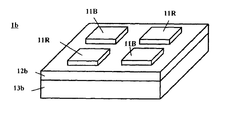
図3は、光源部1bの構成を示す図である。光源部1bは、基板12bと、基板112b上に形成された赤色LED素子11Rを2つ、青色LED素子11Bを2つ有する。
FIG. 3 is a diagram illustrating a configuration of the
なお、この照明装置10では、青色LED素子、赤色LED素子よりも、緑色LED素子の数を多く配置している。このように異なる光源数としているのは、照明装置10が白色光を出力することができるようにするためである。緑色は青色、赤色と比較して視感度が高く、輝度(cd/m2)を他の色よりも高くする必要がある。そこで、緑色のLEDの個数を他色のLEDの個数よりも多くすることで、輝度不足の問題を解消しても良い。
In the
或いは、所定のスペクトルを有する3色のLED光源(赤、青、緑の各色光のLED光源の出射光量をLr、Lb、Lgとする)を用いて白色光を出射させる場合において、各色(赤、青、緑)の光量比をLr’:Lb’:Lg’であるとき白色光を発生可能であることが分かっている場合、Lr/Lr’、Lb/Lb’、Lg/Lg’のうち、最も小さい色光の光源の数を多くするようにしても良い。 Alternatively, when white light is emitted using LED light sources of three colors having a predetermined spectrum (the light emission amounts of the LED light sources of red, blue, and green are Lr, Lb, and Lg), each color (red When it is known that white light can be generated when the light quantity ratio of Lr ′: Lb ′: Lg ′ is Lr / Lr ′, Lb / Lb ′, and Lg / Lg ′ The number of light sources having the smallest color light may be increased.
なお、上記の光源部1a、1bの例では、光源の個数を多くしたい色を光源部1aに配置し、それ以外の2色を光源部1bに配置している。
In the example of the
図4は、直線偏光生成部2aの構成を示す図である。直線偏光生成部2aは、偏光ビームスプリッタ21a、21b、21c、21dからなる偏光ビームスプリッタアレイ21と、偏光ビームスプリッタ21b、21cの光出射側に配置された2分の1波長板22a、22bと、偏光ビームスプリッタ21a、21dの光入射側に配置された反射ミラー23a、23bと、から成る。
FIG. 4 is a diagram illustrating a configuration of the linearly polarized
ランダム偏光光が、偏光ビームスプリッタ21b、21cに入射すると、P偏光光は、偏光ビームスプリッタ21b、21cをそれぞれ透過する。
When the randomly polarized light enters the
一方、S偏光光については、偏光ビームスプリッタ21b、又は21cで反射して、偏光ビームスプリッタ21a又は21dの方向へ進む。偏光ビームスプリッタ21a、21dへ進んだ光はそれぞれ反射する。そして、それぞれの光は、2分の1波長板22a、22bによりその偏光方向が90度回転されてP偏光光となって直線偏光生成部2aから出射されて、偏光依存性反射部3へ向かう。
On the other hand, the S-polarized light is reflected by the
なお、偏光ビームスプリッタ21a、21dの光入射側に反射ミラー23が設けられているのは、光源部1aからの光が直接偏光ビームスプリッタ21a、21dに入るのを防ぐためである。光源部1aからの光が直接偏光ビームスプリッタ21a、21dに入ると、上記例ではS偏光光が直線偏光生成部2aから出射されてしまうからである。
The reason why the reflection mirror 23 is provided on the light incident side of the
なお、偏光ビームスプリッタ21a、21dの光入射側に設けるのは、上記の反射ミラー23に限る必要はなく、遮光できる部材であればよい。
Note that the light beam incident side of the
また、偏光ビームスプリッタ21a、21dに代えて、反射ミラーを用いても良い。
Further, instead of the
図5は、直線偏光生成部2bの構成を示す図である。同図では、図4の直線偏光生成部2aと機能が同一である部材については同一の符号を付している。
FIG. 5 is a diagram illustrating a configuration of the linearly polarized
偏光ビームスプリッタ21b、21cを透過したP偏光は、2分の1波長板22cによりS偏光に変換される。
The P-polarized light transmitted through the
一方、偏光ビームスプリッタ21b、又は21cで反射するS偏光光については、S偏光のまま、偏光依存性反射部3へ向かう。
On the other hand, the S-polarized light reflected by the
図6は、上記照明装置10を用いた投写型映像表示装置100を示す図である。投写型映像表示装置100は、上記説明した照明装置10と、液晶パネル31、投写レンズ32等からなる。
FIG. 6 is a diagram showing a
液晶パネル31は、RGBカラーフィルタを備えた構造、或いはRGBカラーフィルタを備えない構造を有する。RGBカラーフィルタを備える構造の液晶パネル31を用いる場合には、全LED光源を同時点灯して白色光を液晶パネル31に導く。前記RGBカラーフィルタを備えない構造の液晶パネル31を用いる場合には、各色LED光源を時分割で色毎順次に所定時間点灯させると共に、この所定時間点灯のタイミングに同期させて液晶パネル31に各色の映像信号を供給する。
The
液晶パネル31を透過することで変調された光(映像光)は、投写レンズ32によって拡大投写され、図示しないスクリーン上に投影表示される。
The light (image light) modulated by transmitting through the
なお、上記の波長依存性偏光回転部4は、光源部1aからの光と、光源部1bからの光を共にP偏光光にするものであったが、共にS偏光光にするものでも良い。この場合、波長依存性偏光回転部4を、緑色光に対しては2分の1波長板として作用し、青色光、赤色光に対しては波長板として作用しないよう設計することで実現できる。
Note that the wavelength-dependent
なお、上記の投写型映像表示装置100の液晶パネル31は、本願発明のライトバルブ(或いはフルカラーライトバルブ)の一実施例に相当するものであるが、本願発明のライトバルブの他の実施例としては、DMD(デジタルマイクロミラーデバイス:登録商標)を用いたDLP(デジタル・ライト・プロセッシング:登録商標)によるものであっても良い。DMDにおいては、液晶パネルのように入射光の偏光方向を所定方向に揃えておく必要はないので、照明装置10において波長依存性偏光回転部4は不要である。
The
(第2の実施形態)
図7は、照明装置20の構成を示す図である。照明装置20は、光源部1c、1d、波長依存性反射部16、ロッドインテグレータ5などで構成される。
(Second Embodiment)
FIG. 7 is a diagram illustrating a configuration of the lighting device 20. The illumination device 20 includes
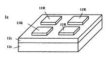
光源部1cは赤色LED素子11Rを4つ備え(図8参照)、光源部1dは青色LED素子11Bを2つ、緑色LED素子11Gを2つ備える(図9参照)。
The
波長依存性反射部16は、光源部1cからの赤色光を透過させ、光源部1dからの青色光、緑色光を反射させて、光源部1cからの光、及び、光源部1dからの光を同一方向、又は略同一方向に導く。この波長依存性反射部16は、例えばダイクロイックミラーにより実現される。
The wavelength
なお、ロッドインテグレータ5の後段(投写光学系側)にはそれぞれのランダム偏光光を同じ偏光方向の直線偏光に変換する(図示しない)偏光変換素子が設けられる。或いは、偏光変換素子は、ロッドインテグレータ5の前段に設けられても良い。
A polarization conversion element (not shown) for converting each randomly polarized light into linearly polarized light having the same polarization direction is provided at the subsequent stage (projection optical system side) of the
(第3の実施形態)
図10は、本願発明の他の照明装置30を示す図である。照明装置30は、光源部1a、1b、時分割ミラー17、ロッドインテグレータ5などで構成される。
(Third embodiment)
FIG. 10 is a diagram showing another
図1の照明装置10と同様、光源部1aは、緑色LED素子を4つ備え、光源部1bは赤色LED素子、青色LED素子を2つずつ備える。
As with the
時分割ミラー17は、電圧印加の有無によって反射と透過を切り替えることができるものであり、例えば、スイッチング回折素子であるDigiLens(登録商標)を用いて構成することができる(特表2002−520648号公報(特に、明細書の段落「0008」「0009」参照)、及び特表2002−525646号公報参照)。時分割ミラー17は、図示しないミラー制御回路によって制御される。
The
光源部1a、1bの各色光源は、色毎に時分割にオンオフ駆動される。時分割ミラー17は、光源部1a、1bの各色光源のオンオフ駆動に同期してスイッチングされる。
Each color light source of the
例えば、図10を参照して、各色光源は赤→青→緑の順で点灯される。光源部1bの赤色LED素子が点灯しているとき、時分割ミラー17は赤色光を反射させてロッドインテグレータ5の方へ導く(同図(a)を参照)。光源部1bの青色LED素子が点灯しているとき、時分割ミラー17は、青色光を反射させてロッドインテグレータ5の方へ導く(同図(a)を参照)。光源部1cの緑色LED素子が点灯しているとき、時分割ミラー17は、緑色光を透過させてロッドインテグレータ5の方へ導く(同図(a)を参照)。
For example, referring to FIG. 10, each color light source is turned on in the order of red → blue → green. When the red LED element of the
即ち、時分割ミラー17を制御するミラー制御回路は、所定の光源が点灯しているときに時分割ミラーを反射状態とし(電圧の印加又は非印加)、他の所定の光源が点灯しているときに時分割ミラーを透過状態とする(電圧の非印加又は印加)ものである。
That is, the mirror control circuit that controls the
(他の光源色の配置例)
各光源部に配置するLED素子は上記の色パターンに限られるものではない。
(Other light source color arrangement examples)
The LED elements arranged in each light source unit are not limited to the above color pattern.
例えば、上記第1の実施形態においては、光源部1aに青色LED素子11Bを4つ配置し、光源部1dに赤色LED素子11Rを2つ、緑色LED素子11Gを2つ配置しても良い。この場合、波長依存性偏光回転部4は、例えば、青色光に対しては2分の1波長板として作用し、緑色光、赤色光としては波長板として作用しないようなものに設計される必要がある。
For example, in the first embodiment, four
また、上記例では、各光源部1a〜1dには、LED素子を4つずつ配置(2×2配列)しているが、個数はこれに限られない。例えば、3×3配列、5×5配列、4×3配列、或いは多角形配列でも良い。 In the above example, four LED elements are arranged (2 × 2 array) in each of the light source units 1a to 1d, but the number is not limited to this. For example, a 3 × 3 array, a 5 × 5 array, a 4 × 3 array, or a polygon array may be used.
或いは、上記第2の実施形態においては、光源部1cに青色LED素子11Bを4つ配置し、光源部1dに赤色LED素子11Bを2つ、緑色LED素子11Gを2つ配置しても良い。このとき、波長依存性反射部16は、光源部1cからの青色光を透過させ、光源部1dからの緑色光、赤色光を反射させて、光源部1cからの光、及び、光源部1dからの光を同一方向、又は略同一方向に導くよう設計される。
Alternatively, in the second embodiment, four
或いは、図8の光源部1cに代えて、図11で示すような光源部1c’を採用しても良い。図8の光源部1cは、同一又は略同一波長の赤色LED素子11Rを4つ備えるものだった。これに対し、光源部1c’は、第1の波長(例えば600nm)の赤色LED素子11R1を2個、第2の波長(例えば630nm)の赤色LED素子11R2を2個、備える。このように同じ色でも波長が若干異なる2種類のLED素子を用いることにより、照明装置の色再現性を改善することができる。或いは、赤色LED素子11R1、11R2に代えて、第1の波長の緑色LED素子と第2の波長の緑色LED素子、或いは、第1の波長の青色LED素子と第2の波長の青色LED素子、を備えても良い。
Alternatively, instead of the
また、図2の光源部1aに代えて、波長が異なる2種類の緑色LED素子を採用することで、照明装置10の色再現性を改善させても良い。
In addition, the color reproducibility of the
また、上記の赤色、青色、緑色に加えて、第4色の固体光源素子を用いてもよい。例えば、黄色光源を採用することで、照明装置の色再現性を向上させたり、照明光の輝度を向上させたりすることができる。更には、第5色、第6色の固体光源素子を更に用いて色再現性をさらに向上させても良い。例えば、シアンやマジェンタ等の色を光源に用いても良い。或いは黄色に変えて、シアン、マジェンタ等を第4色光源として用いても良い。 In addition to the above red, blue, and green, a fourth color solid light source element may be used. For example, by adopting a yellow light source, it is possible to improve the color reproducibility of the lighting device or improve the luminance of the illumination light. Furthermore, the color reproducibility may be further improved by further using solid light source elements of the fifth and sixth colors. For example, a color such as cyan or magenta may be used as the light source. Alternatively, cyan, magenta, etc. may be used as the fourth color light source instead of yellow.
(複数の照明装置を備えた投写型映像表示装置)
図12は、複数の照明装置を用いた投写型映像表示装置200を示す図である。投写型映像表示装置200は、複数の照明装置40(40a、40b)、液晶パネル41、42、合成手段43、投写レンズ44等からなる。
(Projection-type image display device with multiple lighting devices)
FIG. 12 is a diagram showing a
照明装置40(40a、40b)の構成は上記説明した照明装置40の構成とほぼ同じである。但し、照明装置40aと40bは異なる色の光源を備えており、照明装置10aのごとく、白色光を出射しない点で相違する。例えば、照明装置40aは、赤色、黄色の光源を備え、照明装置40bは、青色、緑色の光源を備えている。照明装置40aから出射される光は、液晶パネル41を透過することで変調される。この液晶パネル41へは、赤色、黄色の映像信号が、図示しない液晶表示パネルドライバから供給される。照明装置40bから出射される光は、液晶パネル42を透過することで変調される。この液晶パネル42へは、青色、緑色の映像信号が、図示しない液晶表示パネルドライバから供給される。液晶パネル41で変調された光と、液晶パネル42で変調された光は、合成手段43で合成され、投写レンズ44によって拡大投写され、図示しないスクリーン上に投影表示される。
The configuration of the illumination device 40 (40a, 40b) is substantially the same as the configuration of the illumination device 40 described above. However, the
合成手段43は、偏光ビームスプリッタ、若しくは、ダイクロイックミラー等で構成される。合成手段43が偏光ビームスプリッタの場合、液晶パネル41を透過した光がP偏光、液晶パネル42を透過した光がS偏光となるよう、照明装置40、及び、液晶パネル41、42が設計される。合成手段43がダイクロイックミラーの場合、ダイクロイックミラーは赤色、黄色を透過させ、青色、緑色を反射させるよう設計される。
The synthesizing
或いは、上記投写型映像表示装置200において、照明装置40に代えて、白色光を出射する照明装置10を用いても良い。この場合、合成手段43には、偏光ビームスプリッタが用いられる。
Alternatively, in the
また、上記では、合成手段43の前段に光変調手段(液晶パネル41、液晶パネル42)を配置していたが、光変調手段を合成手段43の後段に配置するものであっても良い。例えば合成手段43と投写レンズ44の間に液晶パネルを1つ配置しても良い。この場合、液晶パネルには、赤色、黄色、青色、緑色の映像信号が、図示しない液晶表示パネルドライバから供給される。
In the above description, the light modulation means (the
また、上記の投写型映像表示装置200においても、液晶パネルに代えて、DLPをライトバルブに用いても良い。
Also in the
今回開示された実施の形態、及び実験例はすべての点で例示であって制限的なものではないと考えられるべきである。本発明の範囲は、上記した実施の形態の説明ではなくて特許請求の範囲によって示され、特許請求の範囲と均等の意味および範囲内でのすべての変更が含まれることが意図される。 It should be considered that the embodiments and experimental examples disclosed herein are illustrative and non-restrictive in every respect. The scope of the present invention is shown not by the above description of the embodiments but by the scope of claims for patent, and is intended to include meanings equivalent to the scope of claims for patent and all modifications within the scope.
例えば、上記の実施形態では、各LED素子は、同一の基板上に配置されるものとして説明したが、別々の基板上に配置されるものであっても良い。 For example, in the above embodiment, each LED element has been described as being disposed on the same substrate, but may be disposed on a separate substrate.
上記では本願発明の「光インテグレータ」の実施例としてロッドインテグレータを挙げたが、光インテグレータとしては、フライアイレンズ(群)であっても良い。 In the above description, the rod integrator is described as an example of the “optical integrator” of the present invention. However, the optical integrator may be a fly-eye lens (group).
上記では本願発明の「光源」の実施例としてLED素子を挙げたが、LED素子以外の固体光源素子であっても良い。或いは、固体光源素子以外の小型の光源であっても良い。 In the above description, the LED element is described as an example of the “light source” of the present invention, but a solid light source element other than the LED element may be used. Alternatively, a small light source other than the solid light source element may be used.
1a、1b 光源部
2a、2b 直線偏光生成部
3 偏光依存性反射部
4 波長依存性偏光変換部
5 ロッドインテグレータ
10 照明装置
11R 赤色LED素子
11G 緑色LED素子
11B 青色LED素子
21 偏光ビームスプリッタアレイ
21a、21b、21c、21d 偏光ビームスプリッタ
22 2分の1波長板
100 投写型映像表示装置
DESCRIPTION OF
Claims (21)
前記3色のうちの第1色光源を備えてなる第1光源部と、
前記3色のうち、第2及び第3色光源を備え、前記第1光源部とは光出射方向が異なる第2光源部と、
前記第1、第2光源部からの各色光を合成して同一又は略同一方向に導く合成手段と、を備えた、照明装置。
A lighting device including light sources of at least three colors of red, blue, and green,
A first light source unit comprising a first color light source of the three colors;
Of the three colors, a second light source unit including second and third color light sources, and a light emitting direction different from the first light source unit;
And a combining unit that combines the respective color lights from the first and second light source units and guides them in the same or substantially the same direction.
The number of color light sources arranged in the first and second light source units is set so that the combining unit can generate white light by combining the color lights from the first and second light source units. Item 2. The lighting device according to Item 1.
前記第1光源部からのランダム偏光光を第1の偏光方向の直線偏光に変換する第1偏光変換手段と、
前記第2光源部からのランダム偏光光を第2の偏光方向の直線偏光に変換する第2偏光変換手段と、
前記第1、第2偏光変換手段からの出射光のいずれか一方の偏光光を反射させ、他方を透過させることにより、前記第1、第2光源部からの光を同一方向又は略同一方向に導く偏光依存性反射手段を備える、請求項1又は2記載の照明装置。
The synthesis means includes
First polarization conversion means for converting randomly polarized light from the first light source unit into linearly polarized light in a first polarization direction;
Second polarization conversion means for converting randomly polarized light from the second light source unit into linearly polarized light in a second polarization direction;
By reflecting one of the polarized light emitted from the first and second polarization conversion means and transmitting the other, the light from the first and second light source units is directed in the same direction or substantially in the same direction. The lighting device according to claim 1, further comprising a polarization-dependent reflecting means for guiding the light.
The illuminating device according to claim 3, further comprising wavelength-dependent polarization rotation means for converting the polarization direction of the light emitted from the first and second polarization conversion means into the same direction or substantially the same direction.
前記第1、第2光源部からの出射光のいずれか一方を反射させ、他方を透過させる波長依存性反射手段を備える、請求項1又は2記載の照明装置。
The synthesis means includes
The illumination device according to claim 1, further comprising wavelength-dependent reflection means that reflects either one of the light emitted from the first and second light source units and transmits the other.
所定領域内に、複数個の第2色光源、及び、複数個の第3色光源が配置されてなり、
前記第2色光源、及び、前記第3色光源の少なくとも何れかは、それぞれの光源が前記所定領域の中心に対して点対称に配置される、請求項1ないし5のいずれか1項に記載の照明装置。
The second light source unit is
A plurality of second color light sources and a plurality of third color light sources are arranged in a predetermined area,
6. The device according to claim 1, wherein at least one of the second color light source and the third color light source is arranged in point symmetry with respect to the center of the predetermined region. Lighting equipment.
The illuminating device according to claim 1, further comprising a fourth color light source in either the first or second light source unit.
該第1光源部は、所定領域内に、複数個の第1色光源、及び、複数個の第4色光源が配置されてなり、
前記第1色光源、及び、前記第4色光源の少なくとも何れかは、それぞれの光源が前記所定領域の中心に対して点対称に配置される、請求項1ないし6のいずれか1項に記載の照明装置。
The first light source unit further includes a fourth color light source,
The first light source unit includes a plurality of first color light sources and a plurality of fourth color light sources arranged in a predetermined area.
7. The device according to claim 1, wherein at least one of the first color light source and the fourth color light source is arranged in point symmetry with respect to the center of the predetermined region. Lighting equipment.
前記第1の発光波長である第1色第1波長光源と、
前記第1の発光波長よりも短い第2の発光波長である第1色第2波長光源と、を備えた、請求項1ないし8のいずれか1項に記載の照明装置。
The first light source unit is
A first color first wavelength light source that is the first emission wavelength;
The lighting device according to claim 1, further comprising: a first color second wavelength light source having a second emission wavelength shorter than the first emission wavelength.
所定領域内に、複数個の前記第1色第1波長光源、及び、複数個の前記第1色第2波長光源、が配置されてなり、
前記第1色第1波長光源、及び、前記第1色第2波長光源の少なくとも何れかは、それぞれの光源が前記所定領域の中心に対して点対称に配置される請求項9記載の照明装置。
The first light source unit is
A plurality of the first color first wavelength light sources and a plurality of the first color second wavelength light sources are arranged in a predetermined region,
The lighting device according to claim 9, wherein at least one of the first color first wavelength light source and the first color second wavelength light source is arranged symmetrically with respect to the center of the predetermined region. .
前記第1光源部とは光出射方向が異なる第2光源部と、
前記第1、第2光源部からの各色光を合成して同一又は略同一方向に導く合成手段と、を備え、
前記合成手段は、
前記第1光源部からのランダム偏光光を第1の偏光方向の直線偏光に変換する第1偏光変換手段と、
前記第2光源部からのランダム偏光光を第2の偏光方向の直線偏光に変換する第2偏光変換手段と、
前記第1、第2偏光変換手段からの出射光のいずれか一方の偏光光を反射させ、他方を透過させることにより、前記第1、第2光源部からの光を同一方向又は略同一方向に導く偏光依存性反射手段を備える照明装置。
A first light source unit;
A second light source unit having a light emission direction different from that of the first light source unit;
And combining means for combining the respective color lights from the first and second light source sections and guiding them in the same or substantially the same direction,
The synthesis means includes
First polarization conversion means for converting randomly polarized light from the first light source unit into linearly polarized light in a first polarization direction;
Second polarization conversion means for converting randomly polarized light from the second light source unit into linearly polarized light in a second polarization direction;
By reflecting one of the polarized light emitted from the first and second polarization conversion means and transmitting the other, the light from the first and second light source units is directed in the same direction or substantially in the same direction. An illumination device comprising a polarization-dependent reflecting means for guiding.
The illuminating device according to claim 11, further comprising wavelength-dependent polarization rotation means for converting the polarization direction of the light emitted from the first and second polarization conversion means into the same direction or substantially the same direction.
The illumination device according to any one of claims 1 to 12, further comprising an integration unit that uniformizes light emitted from the synthesis unit on an illumination target.
The lighting device according to claim 1, wherein the number of light sources arranged in the first light source unit and the total number of light sources arranged in the second light source unit are the same. .
The lighting device according to claim 1, wherein the light source is a solid light source element.
前記合成手段は、
電圧印加の有無によって反射と透過の切り替えることができる時分割反射手段と、
所定の光源が点灯しているときに前記時分割反射手段を反射状態とし、他の所定の光源が点灯しているときに前記時分割反射手段を透過状態とする素子制御手段と、を備えた、請求項1ないし15のいずれか1項に記載の照明装置。
A lighting control means for sequentially lighting the first to third color light sources in a time-sharing manner;
The synthesis means includes
Time-division reflecting means capable of switching between reflection and transmission according to the presence or absence of voltage application;
Element control means for setting the time-division reflecting means in a reflective state when a predetermined light source is turned on, and for making the time-division reflecting means in a transmissive state when another predetermined light source is turned on. The lighting device according to any one of claims 1 to 15.
The lighting device according to any one of claims 1 to 15, wherein each color light is always emitted during illumination.
The illumination device according to any one of claims 1 to 16, wherein each color light is emitted in a time division manner during illumination.
前記照明装置の出射側に設けられた1つのフルカラーライトバルブと、
前記フルカラーライトバルブを経て光変調された映像光を投写する投写手段と、を備えたことを特徴とする、投写型映像表示装置。
An illumination device according to claim 17;
One full-color light bulb provided on the exit side of the illumination device;
A projection type image display apparatus comprising: projection means for projecting image light that is light-modulated through the full-color light valve.
前記照明装置の出射側に設けられた1つのライトバルブと、
色光の出射タイミングに同期して前記ライトバルブに各色用の映像信号を供給する手段と、
前記ライトバルブを経ることで得られた映像光を投写する投写手段と、を備えたことを特徴とする投写型映像表示装置。
The lighting device according to claim 18;
One light valve provided on the exit side of the illumination device;
Means for supplying a video signal for each color to the light valve in synchronization with the emission timing of the color light;
And a projection means for projecting image light obtained by passing through the light valve.
それぞれの照明装置の出射側にそれぞれ設けられたライトバルブと、
色光の出射タイミングに同期して前記ライトバルブに各色用の映像信号を供給する手段と、
前記ライトバルブからの出射光を色合成する色合成手段と、
前記合成手段を経ることで得られた映像光を投写する投写手段と、を備えたことを特徴とする投写型映像表示装置。
A plurality of lighting devices according to claim 17 or 18,
A light valve provided on the exit side of each lighting device;
Means for supplying a video signal for each color to the light valve in synchronization with the emission timing of the color light;
Color synthesizing means for color synthesizing light emitted from the light valve;
And a projection means for projecting image light obtained by passing through the synthesizing means.
Priority Applications (2)
| Application Number | Priority Date | Filing Date | Title |
|---|---|---|---|
| JP2005160687A JP2006337609A (en) | 2005-05-31 | 2005-05-31 | Lighting system and projection type video display apparatus |
| US11/268,732 US7434945B2 (en) | 2004-11-10 | 2005-11-08 | Illuminating device and projection type video display apparatus |
Applications Claiming Priority (1)
| Application Number | Priority Date | Filing Date | Title |
|---|---|---|---|
| JP2005160687A JP2006337609A (en) | 2005-05-31 | 2005-05-31 | Lighting system and projection type video display apparatus |
Publications (1)
| Publication Number | Publication Date |
|---|---|
| JP2006337609A true JP2006337609A (en) | 2006-12-14 |
Family
ID=37558230
Family Applications (1)
| Application Number | Title | Priority Date | Filing Date |
|---|---|---|---|
| JP2005160687A Pending JP2006337609A (en) | 2004-11-10 | 2005-05-31 | Lighting system and projection type video display apparatus |
Country Status (1)
| Country | Link |
|---|---|
| JP (1) | JP2006337609A (en) |
Cited By (14)
| Publication number | Priority date | Publication date | Assignee | Title |
|---|---|---|---|---|
| JP2010072012A (en) * | 2008-09-16 | 2010-04-02 | Canon Inc | Image projection device |
| JP2010528328A (en) * | 2007-05-18 | 2010-08-19 | スリーエム イノベイティブ プロパティズ カンパニー | Color light synthesis optical system for optical projector |
| WO2011037026A1 (en) | 2009-09-28 | 2011-03-31 | 日本電気株式会社 | Illumination device and projection display device using same |
| JP2011510333A (en) * | 2007-12-14 | 2011-03-31 | イーストマン コダック カンパニー | Projector using separate multi-wavelength light sources |
| WO2011037014A1 (en) | 2009-09-28 | 2011-03-31 | 日本電気株式会社 | Color synthesis optical element, projection display device using same, and method for controlling display thereof |
| JP2012042767A (en) * | 2010-08-20 | 2012-03-01 | Toshiba Corp | Projector |
| WO2012176235A1 (en) * | 2011-06-22 | 2012-12-27 | 日立コンシューマエレクトロニクス株式会社 | Image display device |
| US8870384B2 (en) | 2009-09-28 | 2014-10-28 | Nec Corporation | Projection display device having light source device with color synthesis unit |
| JP2016120104A (en) * | 2014-12-25 | 2016-07-07 | ソニー株式会社 | Lighting device, lighting method, and observation device |
| US9645477B2 (en) | 2014-02-18 | 2017-05-09 | Samsung Electronics Co., Ltd. | Polarization LED module, and lighting device and projector having the same |
| JP2017111210A (en) * | 2015-12-14 | 2017-06-22 | シャープ株式会社 | Light source device and projector including the same |
| JP2019030669A (en) * | 2018-08-27 | 2019-02-28 | ソニー株式会社 | Illuminating device, illumination method and observation device |
| JP2019124801A (en) * | 2018-01-16 | 2019-07-25 | セイコーエプソン株式会社 | Illumination device and projector |
| US10908430B2 (en) | 2014-12-25 | 2021-02-02 | Sony Corporation | Medical imaging system, illumination device, and method |
-
2005
- 2005-05-31 JP JP2005160687A patent/JP2006337609A/en active Pending
Cited By (22)
| Publication number | Priority date | Publication date | Assignee | Title |
|---|---|---|---|---|
| JP2010528328A (en) * | 2007-05-18 | 2010-08-19 | スリーエム イノベイティブ プロパティズ カンパニー | Color light synthesis optical system for optical projector |
| JP2011510333A (en) * | 2007-12-14 | 2011-03-31 | イーストマン コダック カンパニー | Projector using separate multi-wavelength light sources |
| JP2010072012A (en) * | 2008-09-16 | 2010-04-02 | Canon Inc | Image projection device |
| US9400419B2 (en) | 2009-09-28 | 2016-07-26 | Nec Corporation | Illumination device and projection display device using same |
| WO2011037026A1 (en) | 2009-09-28 | 2011-03-31 | 日本電気株式会社 | Illumination device and projection display device using same |
| WO2011037014A1 (en) | 2009-09-28 | 2011-03-31 | 日本電気株式会社 | Color synthesis optical element, projection display device using same, and method for controlling display thereof |
| US9819919B2 (en) | 2009-09-28 | 2017-11-14 | Nec Corporation | Illumination device and projection display device using same |
| US8870384B2 (en) | 2009-09-28 | 2014-10-28 | Nec Corporation | Projection display device having light source device with color synthesis unit |
| US9429761B2 (en) | 2009-09-28 | 2016-08-30 | Nec Corporation | Color synthesis optical element, projection-type display device using same, and method for controlling display thereof |
| JP2012042767A (en) * | 2010-08-20 | 2012-03-01 | Toshiba Corp | Projector |
| US8757808B2 (en) | 2010-08-20 | 2014-06-24 | Kabushiki Kaisha Toshiba | Projector having light emission devices |
| US9116349B2 (en) | 2011-06-22 | 2015-08-25 | Hitachi Maxell, Ltd. | Image display device |
| JPWO2012176235A1 (en) * | 2011-06-22 | 2015-02-23 | 日立コンシューマエレクトロニクス株式会社 | Image display device |
| WO2012176235A1 (en) * | 2011-06-22 | 2012-12-27 | 日立コンシューマエレクトロニクス株式会社 | Image display device |
| US9645477B2 (en) | 2014-02-18 | 2017-05-09 | Samsung Electronics Co., Ltd. | Polarization LED module, and lighting device and projector having the same |
| JP2016120104A (en) * | 2014-12-25 | 2016-07-07 | ソニー株式会社 | Lighting device, lighting method, and observation device |
| US10908430B2 (en) | 2014-12-25 | 2021-02-02 | Sony Corporation | Medical imaging system, illumination device, and method |
| US11647900B2 (en) | 2014-12-25 | 2023-05-16 | Sony Corporation | Medical imaging system, illumination device, and method |
| JP2017111210A (en) * | 2015-12-14 | 2017-06-22 | シャープ株式会社 | Light source device and projector including the same |
| JP2019124801A (en) * | 2018-01-16 | 2019-07-25 | セイコーエプソン株式会社 | Illumination device and projector |
| JP7098937B2 (en) | 2018-01-16 | 2022-07-12 | セイコーエプソン株式会社 | Lighting equipment and projectors |
| JP2019030669A (en) * | 2018-08-27 | 2019-02-28 | ソニー株式会社 | Illuminating device, illumination method and observation device |
Similar Documents
| Publication | Publication Date | Title |
|---|---|---|
| JP2006337609A (en) | Lighting system and projection type video display apparatus | |
| JP5951744B2 (en) | Projector and its illumination device | |
| EP2778741B1 (en) | Multi-colour illumination apparatus | |
| JP2006023436A (en) | Illuminating apparatus and projector | |
| WO2016157365A1 (en) | Projector and image light projection method | |
| TW201109726A (en) | Light source device, projector and projection method | |
| US20130083294A1 (en) | Illumination system and projection apparatus | |
| JPWO2018073893A1 (en) | Projector and image display method | |
| JP6406736B2 (en) | Projector and image display method | |
| EP3500893A1 (en) | Illumination device and image projection device | |
| JP3972837B2 (en) | Illumination device, projector and optical device | |
| JP2007065408A (en) | Illuminating device and projection type video display device | |
| JP2004126203A (en) | Optical engine | |
| JP2007065412A (en) | Illuminating device and projection type video display device | |
| JP2009003062A (en) | Light source device and illuminating device having it | |
| JP3944648B2 (en) | Lighting device and projector | |
| JP2005189277A (en) | Light source device and image display device | |
| JP2010097003A (en) | Lighting optical system for two plate type projector | |
| JP2006337595A (en) | Illuminator and projection type video display device | |
| KR101057996B1 (en) | Projection type image display device | |
| JP2007093970A (en) | Projection type image display apparatus | |
| JP4118244B2 (en) | Illumination device and projection display device | |
| JP2007003847A (en) | Illuminator and projection type image display device | |
| JP2004151173A (en) | Optical engine | |
| JP2005292502A (en) | Illumination device for projection type display, and projection type projector |