JP5415757B2 - Camera support and individual camera assembly - Google Patents
Camera support and individual camera assembly Download PDFInfo
- Publication number
- JP5415757B2 JP5415757B2 JP2008516296A JP2008516296A JP5415757B2 JP 5415757 B2 JP5415757 B2 JP 5415757B2 JP 2008516296 A JP2008516296 A JP 2008516296A JP 2008516296 A JP2008516296 A JP 2008516296A JP 5415757 B2 JP5415757 B2 JP 5415757B2
- Authority
- JP
- Japan
- Prior art keywords
- camera
- camera body
- base plate
- plate
- wedge
- Prior art date
- Legal status (The legal status is an assumption and is not a legal conclusion. Google has not performed a legal analysis and makes no representation as to the accuracy of the status listed.)
- Expired - Fee Related
Links
Images


Classifications
-
- F—MECHANICAL ENGINEERING; LIGHTING; HEATING; WEAPONS; BLASTING
- F16—ENGINEERING ELEMENTS AND UNITS; GENERAL MEASURES FOR PRODUCING AND MAINTAINING EFFECTIVE FUNCTIONING OF MACHINES OR INSTALLATIONS; THERMAL INSULATION IN GENERAL
- F16M—FRAMES, CASINGS OR BEDS OF ENGINES, MACHINES OR APPARATUS, NOT SPECIFIC TO ENGINES, MACHINES OR APPARATUS PROVIDED FOR ELSEWHERE; STANDS; SUPPORTS
- F16M13/00—Other supports for positioning apparatus or articles; Means for steadying hand-held apparatus or articles
-
- F—MECHANICAL ENGINEERING; LIGHTING; HEATING; WEAPONS; BLASTING
- F16—ENGINEERING ELEMENTS AND UNITS; GENERAL MEASURES FOR PRODUCING AND MAINTAINING EFFECTIVE FUNCTIONING OF MACHINES OR INSTALLATIONS; THERMAL INSULATION IN GENERAL
- F16M—FRAMES, CASINGS OR BEDS OF ENGINES, MACHINES OR APPARATUS, NOT SPECIFIC TO ENGINES, MACHINES OR APPARATUS PROVIDED FOR ELSEWHERE; STANDS; SUPPORTS
- F16M11/00—Stands or trestles as supports for apparatus or articles placed thereon Stands for scientific apparatus such as gravitational force meters
- F16M11/02—Heads
- F16M11/04—Means for attachment of apparatus; Means allowing adjustment of the apparatus relatively to the stand
- F16M11/041—Allowing quick release of the apparatus
-
- F—MECHANICAL ENGINEERING; LIGHTING; HEATING; WEAPONS; BLASTING
- F16—ENGINEERING ELEMENTS AND UNITS; GENERAL MEASURES FOR PRODUCING AND MAINTAINING EFFECTIVE FUNCTIONING OF MACHINES OR INSTALLATIONS; THERMAL INSULATION IN GENERAL
- F16M—FRAMES, CASINGS OR BEDS OF ENGINES, MACHINES OR APPARATUS, NOT SPECIFIC TO ENGINES, MACHINES OR APPARATUS PROVIDED FOR ELSEWHERE; STANDS; SUPPORTS
- F16M11/00—Stands or trestles as supports for apparatus or articles placed thereon Stands for scientific apparatus such as gravitational force meters
- F16M11/02—Heads
- F16M11/16—Details concerning attachment of head-supporting legs, with or without actuation of locking members thereof
-
- F—MECHANICAL ENGINEERING; LIGHTING; HEATING; WEAPONS; BLASTING
- F16—ENGINEERING ELEMENTS AND UNITS; GENERAL MEASURES FOR PRODUCING AND MAINTAINING EFFECTIVE FUNCTIONING OF MACHINES OR INSTALLATIONS; THERMAL INSULATION IN GENERAL
- F16M—FRAMES, CASINGS OR BEDS OF ENGINES, MACHINES OR APPARATUS, NOT SPECIFIC TO ENGINES, MACHINES OR APPARATUS PROVIDED FOR ELSEWHERE; STANDS; SUPPORTS
- F16M2200/00—Details of stands or supports
- F16M2200/02—Locking means
- F16M2200/025—Locking means for translational movement
- F16M2200/027—Locking means for translational movement by friction
-
- H—ELECTRICITY
- H04—ELECTRIC COMMUNICATION TECHNIQUE
- H04N—PICTORIAL COMMUNICATION, e.g. TELEVISION
- H04N23/00—Cameras or camera modules comprising electronic image sensors; Control thereof
- H04N23/50—Constructional details
- H04N23/55—Optical parts specially adapted for electronic image sensors; Mounting thereof
Description
本発明は、カメラを取り外し可能に取り付けるためのカメラサポートおよび個々のカメラアセンブリに関する。 The present invention relates to a camera support and an individual camera assembly for removably mounting a camera.
テレビカメラの分野における周知のカメラアセンブリは、いわゆるスーパーエキスパンダーであり、三脚などに取り付けのための一種のフレームと見なすことができ、レンズを支え、異なる種類のカメラボディをレンズと協力し合うように解除可能に連結することができる。 Well-known camera assemblies in the field of television cameras are so-called super-expanders, which can be considered as a kind of frame for mounting on a tripod, etc., to support the lens and to cooperate different types of camera bodies with the lens. Can be releasably connected.
従来技術のスーパーエキスパンダーは、2つの直交する部材を具え、その第1の一方がこれに取り付けられるレンズの光軸に対して直角に延在し、その第2の方が、レンズが取り付けられるのと反対のカメラボディが解除可能に固定される第1の部材の側方に延在する。 The prior art super expander comprises two orthogonal members, one of which extends perpendicular to the optical axis of the lens attached thereto, the second of which the lens is attached. The opposite camera body extends to the side of the first member fixed releasably.
従来、このようなスーパーエキスパンダーは、カメラボディの前部および後部に解除可能に係合するための第1および第2の係合手段が形成された台板を有し、このカメラボディは、連結するために台板の後部から前部まで移動可能である。第1の係合手段(すなわち前部係合手段)には、テーパ状あり溝の両側を画成して前方に収束する2つのくさびが形成されている。カメラボディは、カメラのくさびの両側が台板のそれらに接触するまで、前記溝へと押し込まれることができるあり形断面のテーパ状くさびを有する。この方法において、カメラボディが前方に動くことができない以外に、これが側方にも垂直にも動くことができない当接位置が画成される。第2、つまり後部係合手段は、台板から離れたステムにより保持された小板によって形成され、カメラの相補的係合手段は、カメラボディをその当接位置まで前方に動かした場合、台板と小板との間に係合するウェブを具えている。 Conventionally, such a super expander has a base plate on which first and second engaging means for releasably engaging with a front part and a rear part of the camera body are formed. In order to do so, it is movable from the rear part to the front part of the base plate. The first engaging means (that is, the front engaging means) is formed with two wedges that define both sides of the tapered groove and converge forward. The camera body has a dovetail tapered taper that can be pushed into the groove until both sides of the camera wedge contact them on the base plate. In this way, a contact position is defined in which the camera body cannot move either sideways or vertically, other than being able to move forward. The second or rear engaging means is formed by a small plate held by a stem remote from the base plate, and the complementary engaging means of the camera is a base when the camera body is moved forward to its contact position. A web is provided that engages between the plate and the platelet.
小板とウェブとの間に、これらを自由に係合および係合解除できることを確実にするため、若干の遊びが必要である。しかしながら、この遊びは、カメラボディの前部が当接位置にあったとしても、カメラボディの後部に若干のがたが残ることを意味する。カメラボディがレンズに対して移動することができる場合、レンズによりカメラボディの感光面に投影される画像も同じような状況となろう。これを回避するため、遊びのない取り付け具をカメラの後部にも設ける必要がある。もちろん、カメラの後部を台板に遊びなく固定するために追加の工具を設けることが可能であるが、これらの工具を操作することは面倒であり、カメラマンがこれを使うのを忘れる危険性がある。 Some play is required between the platelets and the web to ensure that they can be freely engaged and disengaged. However, this play means that even if the front part of the camera body is in the contact position, some play remains on the rear part of the camera body. If the camera body can move relative to the lens, the image projected by the lens onto the photosensitive surface of the camera body will be in a similar situation. In order to avoid this, it is necessary to provide a play-free fitting at the rear of the camera. Of course, it is possible to provide additional tools to secure the rear of the camera to the base plate without play, but operating these tools is cumbersome and there is a risk that the photographer will forget to use it. is there.
さらに、カメラボディが光軸に対して正しく方向付けされずに当接位置に向けて押された場合、レンズに損傷を与える危険性がある。 Furthermore, there is a risk of damaging the lens if the camera body is pushed toward the abutting position without being correctly oriented with respect to the optical axis.
本発明の目的は、カメラボディをその意図した取り付け位置に移動した時に遊びなく自動的にこれを所定位置に固定し、かつレンズに対するカメラボディの安全な取り扱いを特に可能にするカメラサポートおよびカメラアセンブリを提供することである。 An object of the present invention is to provide a camera support and camera assembly that automatically locks the camera body in place without play when it is moved to its intended mounting position, and in particular allows safe handling of the camera body with respect to the lens. Is to provide.
この目的は、第1および第2の係合手段が形成された台板を具え、この台板に沿って係合方向に移動するカメラボディの第1および第2の部材に対し、前記係合手段が解除可能に係合するカメラサポートにより達成され、前記第1の係合手段は前記カメラボディの第1の部材に対する当接位置を画成し、前記第2の係合手段は2つの側壁間に空隙を画成して前記カメラボディのウェブを摺動可能に収容し、前記側壁の一方が他方に向けて移動可能であって第1の係合手段のトリガーに結合され、前記当接位置に達した前記第1の部材によって前記トリガーが操作された場合に前記側壁間に前記ウェブを固定するようになっている。 The object is to provide a base plate on which first and second engaging means are formed, and to engage the first and second members of the camera body moving in the engaging direction along the base plate. Wherein the first engagement means defines an abutting position of the camera body against the first member, and the second engagement means comprises two side walls. An air gap is defined between the camera body web to be slidable, and one of the side walls is movable toward the other and is coupled to a trigger of the first engagement means, When the trigger is operated by the first member having reached the position, the web is fixed between the side walls.
カメラサポートは、側壁が相互に離れるように付勢するための第1のばね(37)を好ましくは具えており、トリガーを操作しない限り、カメラのウェブを側壁間の空隙へと自由に差し込むことができるようになっている。 The camera support preferably includes a first spring (37) for biasing the side walls away from each other so that the camera web can be freely inserted into the gap between the side walls unless the trigger is operated. Can be done.
一方の前記側壁を前記台板の平坦な外側面によって形成することができ、前記平坦な面の穴を通って延在するステムによって前記平坦な面の上に保持される固定板により、他方の側壁を形成することができる。 One of the side walls can be formed by a flat outer surface of the base plate, and a fixing plate held on the flat surface by a stem extending through a hole in the flat surface, Sidewalls can be formed.
固定操作を行うため、くさびを前記ステムの押圧面と前記台板の内側面との間に配することができ、押圧面と台板の内側面との間の空隙へとくさびをさらに押し込んだ場合、固定板が台板の外側面に向けて引っ張られるようになっている。 In order to perform the fixing operation, the wedge can be arranged between the pressing surface of the stem and the inner side surface of the base plate, and the wedge is further pushed into the gap between the pressing surface and the inner side surface of the base plate. In this case, the fixed plate is pulled toward the outer surface of the base plate.
良好に釣り合った引張り力をステムに加えるため、くさびの溝を通ってステムを延在させることができ、押圧面を前記ステムから側方に延在する板に形成することができる。 In order to apply a well balanced tensile force to the stem, the stem can be extended through the groove in the wedge and the pressing surface can be formed on a plate extending laterally from the stem.
ステムが台板へと引き込まれる位置に向けてくさびを付勢するための第2のばねを設けることができ、ステムを引き込むための外部の駆動力を必要としないようになっている。 A second spring for biasing the wedge toward the position where the stem is pulled into the base plate can be provided, and an external driving force for pulling the stem is not required.
くさびを第1の係合手段のトリガーに結合するため、このくさびはカメラボディの移動方向に対して横切る方向に移動可能となるように好ましくは配され、トリガーは移動方向に対して同じく横切る方向に移動可能なばね付勢ラッチに解除可能に係合し、くさびは移動方向に延在する両アームレバーによってラッチに結合される。 In order to couple the wedge to the trigger of the first engaging means, this wedge is preferably arranged so that it can move in a direction transverse to the direction of movement of the camera body, and the trigger is also transverse to the direction of movement. Releasably engages a spring-biased latch that is movable to the wedge and the wedge is coupled to the latch by both arm levers extending in the direction of movement.
この種のカメラサポートは、個々のカメラアセンブリに都合良く使うことができる。カメラアセンブリは、カメラサポートを2つの直交する部材と共に具え、第1のそれがレンズを支持するようになっていると共に第2のそれがカメラボディを第2の部材に解除可能に固定するための第1の固定手段を有し、この第2の部材は前記第1の部材に対する不動部材を有し、前記第1の固定手段が前記可動部材に形成され、この可動部材は、前記第1の固定手段により可動部材に固定された場合、前記カメラボディが前記レンズから間隔をあけられる第1の位置と、前記カメラボディが前記レンズに接続する第2の位置との間を移動可能である。可動部材は、前述したようにカメラサポートの台板に対応している。 This type of camera support can be conveniently used for individual camera assemblies. The camera assembly comprises a camera support with two orthogonal members, a first that is adapted to support the lens and a second that releasably secures the camera body to the second member. 1st fixing means, this 2nd member has an immovable member with respect to said 1st member, and said 1st fixing means is formed in said movable member, and this movable member is said 1st When fixed to the movable member by a fixing means, the camera body is movable between a first position where the camera body is spaced from the lens and a second position where the camera body is connected to the lens. The movable member corresponds to the camera support base plate as described above.
第1の安全手段として、固定手段が固定状態にある場合に限り、可動部材が第2の位置へと移動可能であることをもたらすことができる。従って、カメラボディは、その向きが正しい場合に限り、レンズに接近することができ、カメラボディとレンズの光学面との間での接触の危険性がない。 As a first safety means, the movable member can be moved to the second position only when the fixing means is in a fixed state. Therefore, the camera body can approach the lens only when its orientation is correct, and there is no risk of contact between the camera body and the optical surface of the lens.
この第1の安全手段は、前記可動部材の移動方向に対して直角に移動可能であって、カメラボディを固定および/または固定解除するために利用者により移動させることができる前記固定手段の操作部材と、可動部材が第2の位置にある場合に操作部材をその固定状態に拘束する突起を持った前記不動部材とにより、特に具体化することができる。 The first safety means can be moved at right angles to the moving direction of the movable member, and can be moved by the user to fix and / or unlock the camera body. This can be particularly realized by the member and the immovable member having a protrusion that restrains the operation member in its fixed state when the movable member is in the second position.
第2の安全手段として、可動部材が第2の位置にある場合、固定手段を固定状態に固定することをもたらすことができる。すなわち、カメラボディが非常にレンズに近い場合、カメラボディの偶発的移動がレンズに損傷を与える可能性があり、カメラボディを可動部材から固定解除することができない。 As a second safety means, when the movable member is in the second position, the fixing means can be fixed in a fixed state. That is, if the camera body is very close to the lens, accidental movement of the camera body can damage the lens, and the camera body cannot be unlocked from the movable member.
この第2の安全手段は、前記可動部材の移動方向に対して直角に移動可能であって、カメラボディを固定および/または固定解除するために利用者により移動させることができる前記固定手段の操作部材と、固定手段が非固定状態にある場合、可動部材をその第1の位置に拘束する突起を持った前記不動部材とにより、特に具体化することができる。
The second safety means can be moved at right angles to the moving direction of the movable member, and can be moved by the user to fix and / or unlock the camera body. When the member and the fixing means are in the non-fixed state, it can be particularly embodied by the immovable member having a protrusion that restrains the movable member at the first position.
両方の安全手段を組み込み、かつ操作部材と2つの安全手段の突起とが同じであることが特に望ましい。これは、例えば可動部材の移動方向に対してほぼ直角に延在し、かつ非固定状態にある不動部材の突起の第1の側に面すると共に操作部材が固定状態にある場合に前記第1のブロック面と重ならない第1のブロック面と、その固定状態と非固定状態との間の前記操作部材の移動方向に対してほぼ直交し、かつ可動部材がその第2の位置にある場合に限り、前記突起の第2の側と重なり合う第2のブロック面とを持った操作部材を設けることによって、達成することができる。 It is particularly desirable to incorporate both safety means and that the operating member and the projections of the two safety means are the same. For example, when the operation member is in a fixed state while extending substantially perpendicular to the moving direction of the movable member and facing the first side of the protrusion of the non-fixed stationary member, the first is described above. A first block surface that does not overlap with the block surface, and substantially perpendicular to the moving direction of the operation member between the fixed state and the non-fixed state, and the movable member is in the second position. This can be achieved by providing an operating member having a second block surface that overlaps the second side of the protrusion.
カメラボディおよび可動部材は、固定手段がカメラボディを可動部材に対して固定することを可能にする位置へとカメラボディを案内するために協力し合う案内手段を好ましくは有するべきである。これら協力し合う案内手段は、テーパ状のくさびと、対をなすテーパ状あり溝とを具えることができ、例えば、上述したようにこれらの一方はカメラボディに配されると共に他方が可動部材に配される。加えて、あるいは選択肢として、カメラサポートに対するカメラボディの直線状の移動を厳密に案内するため、一定の幅の協力し合うウェブおよび溝を可動部材およびカメラボディに設けることができる。 The camera body and the movable member should preferably have guiding means that cooperate to guide the camera body to a position that allows the fixing means to lock the camera body relative to the movable member. These cooperating guide means can comprise a tapered wedge and a pair of tapered grooves, for example, one of these is arranged in the camera body and the other is a movable member as described above. Arranged. In addition or as an option, cooperating webs and grooves of constant width can be provided in the movable member and the camera body in order to strictly guide the linear movement of the camera body relative to the camera support.
案内手段は、カメラボディをその固定位置へと可動部材の移動方向と平行に案内することができる。上記安全手段により可動部材が拘束されて非固定状態にあるので、正確に固定されず、それゆえに正確に配されずにカメラボディがレンズにぶつかる危険性がない。 The guiding means can guide the camera body to its fixed position in parallel with the moving direction of the movable member. Since the movable member is restrained by the safety means and is in a non-fixed state, it is not fixed accurately, and therefore there is no risk of the camera body hitting the lens without being accurately arranged.
可動部材は、これが第1および第2の位置よりも第1の部材からさらに遠くに離れ、かつこれが不動部材から固定解除される第3の位置へと移動可能であってよい。この位置において、例えば修理または保守のため、可動部材をカメラサポートから取り除くことが可能である。 The movable member may be movable to a third position where it is further away from the first member than the first and second positions and where it is unlocked from the stationary member. In this position, the movable member can be removed from the camera support, for example for repair or maintenance.
可動部材がその第1の位置からその第2の位置まで移動する場合、可動部材を不動部材に対して自動的かつ解除可能に固定し、これによりカメラボディが両者を連結するのに必要な距離よりもレンズに近付き過ぎるのを阻止するため、第2の固定手段を設けることができる。 When the movable member moves from its first position to its second position, the movable member is automatically and releasably fixed to the immovable member, so that the camera body can connect the two together. In order to prevent being too close to the lens, a second fixing means can be provided.
このカメラアセンブリの場合、可動部材がその第1の位置にあると、カメラボディがカメラサポートに固定されるので、仮に適切な方向付けなく、カメラがその当接位置に向けて強引に押し付けられたとしても、カメラボディと第1の部材に取り付けることができるレンズとの間での接触の危険性がない。製造公差のためにカメラボディが第1の部材にぶつかる前に当接位置に達することができなかったり、あるいは当接位置のカメラボディが第1の部材から遠く離れ過ぎているので、バヨネット結合を完了することが困難であったりするという可能性がない。 In the case of this camera assembly, when the movable member is in the first position, the camera body is fixed to the camera support. Therefore, the camera is forcibly pressed toward the contact position without proper orientation. Even so, there is no risk of contact between the camera body and the lens that can be attached to the first member. Due to manufacturing tolerances, the camera body cannot reach the abutting position before it hits the first member, or the camera body at the abutting position is too far away from the first member. There is no possibility that it will be difficult to complete.
従って、このカメラアセンブリは、カメラボディとレンズとの間の接続において協力し合う種々の部品の位置および寸法に対してあまりにも厳密な公差を課すことを必要とせず、カメラボディをカメラサポートの所定位置に固定すると共にカメラボディをレンズに連結することを可能にする。さらに、カメラボディがレンズに接近する場合、レンズに損傷を与える危険性がない。 Thus, this camera assembly does not require imposing too close tolerances on the positions and dimensions of the various parts that cooperate in the connection between the camera body and the lens, and the camera body is fixed on the camera support. It is possible to fix the position and connect the camera body to the lens. Furthermore, when the camera body approaches the lens, there is no risk of damaging the lens.
本発明のさらなる特徴および利点は、添付図面を参照した次のその実施形態の説明から明白となろう。 Further features and advantages of the present invention will become apparent from the following description of embodiments thereof with reference to the accompanying drawings.
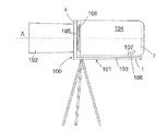
図1を参照してカメラサポートの概略形状が説明されよう。従来のスーパーエキスパンダーのように、このサポートは、台板1と、台板1の前端2に対向し、上部に図示しないレンズが取り付けられる縦壁4とを具えている。図1には壁4の下部のみが描かれている。台板1は、アルミニウムなどで作られる平坦な厚板である。
The general shape of the camera support will be described with reference to FIG. Like a conventional super expander, this support includes a
前端2の近傍において、2つのくさび5が台板1に形成されている。これらくさび5は、台板1の長手方向に延在する縦外側部6と、相互に対向すると共に上方および前方に収束する内側部7とを有し、あり形断面を有する幅の広いテーパ溝8を画成するようになっている。
Two
くさび5の下方には、ラッチ9が台板1の横溝に摺動可能に収容されている。ラッチ9の遠端には、指で容易に押される凹面10が形成され、ラッチ9を台板1に押し込むようになっている。ラッチ9は、テーパ溝8の底にて長穴13を通って突出する円柱状のピン11に連結されている。長穴13は、くさび5の一方に延在し、ラッチ9を押し込んだ場合、ピン11が溝8を出てくさびの開口に収まるようになっている。
Below the
くさび5の一方の外側部6に隣接するトリガー爪14が台板1の穴15に取り付けられている。トリガー爪14は台板1の長手方向に移動可能である。
A
台板1の中央部近傍には、カメラボディの係合手段を形成する直方体形状のブロック16が示されている。カメラボディは、ブロック16に対するその位置を例示するために仮想で図に示されている。ブロック16の底側には、2つのテーパ溝17が形成され、その形状は台板のくさび5に対応している。溝17は,くさび5と対向するブロック16側で広い開口を有するので、その結合をレンズに対して行うためにカメラボディを壁4に向けて押し込んだ場合、くさび5を溝17に係合させることが容易である。溝17の内側がくさび5の内側7に接触する当接位置に達するまで、カメラボディを前方に押し込むことができる。これが起こった場合、一方の溝17の内側に形成されたノッチ18が長穴13と一直線状となり、ピン11がこれと係合することができ、ノッチ18の前壁と接触状態となり、これによってブロック16の後方移動を阻止するようになっている。従って、ブロック16の位置があらゆる遊びを持たずに規定される。
In the vicinity of the center of the
台板1の後端3の近傍には、円形の固定板19が、図1の視点では固定板19の下に完全に隠れている円筒状のステム20(例えば図5参照)により、台板1の上側から間隔をあけて保持されている。
In the vicinity of the
カメラボディは、その後底部に固定されてアンダーカット溝22が形成されるシュープレート21を有する。溝22は、その上部において、固定板19を収容するために充分広く、これに対してその下部においては、ウェブ23が溝の両側から中央に向けて突出し、ステム20の両側にて固定板19と台板1の表面との間で係合するようになっている。
The camera body then has a
図1に示したカメラサポートの形状において、そのブロック16が溝8に係合し、ピン11がノッチ18に係合し、そして固定板19がシュープレート21の溝22に係合するように適切に配された場合、カメラボディはカメラサポートに固定されよう。
In the shape of the camera support shown in FIG. 1, the
カメラサポートにカメラボディを固定する方法を理解するため、非固定状態における台板1の底面図とその断面図とを示す図4および図5に対する参照がここでなされる。この状態において、ラッチ9が台板1に押し付けられ、ピン11がくさび5内に隠されるようになっている。トリガー爪14の一部であるコグ12がラッチ9のノッチ24に係合する。コグ12は圧縮コイルばね25によりノッチ24へと押し込まれて保持される。別なコイルばね26が切欠き27に取り付けられてねじれ負荷の下にあり、ラッチ9の止め金29に対して力を加え、ばね26の端部28が台板1からラッチ9を押し出すように付勢している。コグ12によりブロックされているラッチ9は、この力に従うことができない。
In order to understand how to fix the camera body to the camera support, reference will now be made to FIGS. 4 and 5 showing a bottom view and a cross-sectional view of the
台板1の長手方向切欠き30には、両アームレバー31が軸32に回転可能に保持されている。くさび34は第3のコイルばね33によりレバー31の一端に対して押し付けられ、これによりレバー31の他端がラッチ9の内側端に対して押し付けられる。くさび34は、これに形成された長手方向の溝35を有し、ここにステム20が延在する。くさび34を横切って延在する押圧板36がステム20の端部に固定されている。明瞭性のために図4に示さないが、図5にのみ示す板ばね37は、板36をくさび34に付勢し、くさび34は板36と台板1の内面との間に遊びなく保持されるようになっている。図5の形態において、台板1の上面と固定板19の底側との間の空隙38は充分広く、そこにシュープレート21のウェブ23を係合させることが容易である。
Both arm levers 31 are rotatably held on a
カメラボディを図1に示した位置からこれが固定される位置まで前方に押し込む操作において、ブロック16がトリガー爪14に当接してこれを前端2の方に押し込み、これによってばね25が圧縮されると共にコグ12がノッチ24から取り外される。ここで、ラッチ9はばね26の力に従うことができ、外側に移動する。さて、レバー31は軸32の回りを自由に回転してこれがくさび34の圧力に従うようになっており、くさび34は図4の視点において下方または図5の視点において右に動かされ、従って固定板19を台板1の方に引っ張る。
In the operation of pushing the camera body forward from the position shown in FIG. 1 to the position where it is fixed, the
結果として生ずる状況を図2および図3にて見ることができる。くさび34は、固定板19が台板1に近付いてシュープレート21のウェブ23が台板1と固定板19との間に固定されるまで、ばね33の力に従う。くさび34の傾斜が小さいので、その厚みと狭い方の両端との間の厚みの差を0.5mm以下にすることができると共に図2および図4の形態におけるその2つの位置間の距離を数ミリメートルにすることができ、引っ張り力が固定板19に加わった場合、くさび34を側方に摺動させることができず、シュープレート21をしっかりと遊びなく保持するようになっている。
The resulting situation can be seen in FIGS. The
カメラボディを再び解放する場合、ラッチ9を台板1に押し込むことで充分であり、ピン11が溝8から出てそのくさび5へと移動し、くさび34がレバー13によって後方に押し戻されるようになっており、固定板19が板ばね37によって持ち上げられることを可能にする。従って、カメラボディが固定解除され、後方に引き戻すことができる。コグ12がばね25によりノッチ24へと押し付けられるため、ラッチ9は、他のカメラボディが取り付けられて再び前方のトリガー爪14を押すまで、この位置に保持される。
When releasing the camera body again, it is sufficient to push the
ここで、次の図面にて説明されるカメラアセンブリに対し、特に前述したようなスーパーエキスパンダーに対し、この種類のカメラサポートを具合良く用いることができる。 Here, this kind of camera support can be used well for the camera assembly described in the following drawings, especially for the super-expander as described above.
図6のカメラアセンブリの側面図において、参照符号100は、第1のほぼ垂直な部材4と、第2のほぼ水平な部材101とを有するカメラサポートを示している。垂直部材4は、この部材4の外側に取り付けられるレンズ102の光軸Aに対して直角に延在している。水平部材101は、垂直部材4に強固に連結されると共にこれを三脚などに取り付けるための取り付け具が設けられ、従って不動部材として与えられる第1の概ね板状をなす部材103と、カメラボディ104が取り付けられる第2の概ね板状をなす部材1とを具えている。図6中に実線で示すカメラボディ104および第2の板状部材1の第1の位置において、カメラボディ104と垂直部材4との間に空隙があり、レンズ102およびカメラボディ104のバヨネットカップリング部材105および106は係合し合わない。第2の板状部材1は、図6中に仮想で示す第2の位置へと移動可能であり、カップリング部材105および106が相互に係合してこれらの一方を回転することにより固定することができ、カメラを操作可能にする。実際のバヨネットカップリング部材105および106は従来技術の部分であるので、ここではこれらをさらに詳細に記述しない。
In the side view of the camera assembly of FIG. 6,
手始めにカメラアセンブリおよびその操作の理解を促進するため、カメラボディ104に対する第2およびその接続がここで図7から図11を参照して詳細に説明されよう。図7の板状部材1は、図1〜図5に関してすでに説明したように、台板1と対応している。同じ部品に対して同一の参照符号が用いられる。
To facilitate an understanding of the camera assembly and its operation to begin with, the second and its connection to the
図7に示すように、可動部材1は、アルミニウムなどから作られた平坦な厚板であり、その前端2が垂直部材4に対向している。前端2の近傍において、2つのくさび5が可動部材1に形成されている。くさび5は、可動部材1の長手方向に延在する縦外側部6と、相互に対向して上方および前方に収束する内側部7とを有し、あり形断面を持った幅の広いテーパ溝8を画成するようになっている。
As shown in FIG. 7, the
くさび5の下方には、ラッチ9が可動部材1の横溝に摺動可能に収容されている。ラッチ9の遠端には、指にて容易に押される凹面10が形成され、ラッチ9を台板1に押し込むようになっている。ヘッドは下向き突出部39をさらに有し、この詳細な説明の後の部分で明らかとなろう方法で不動部材103の突起124と協力し合う。ラッチ9は、長穴13を通って突出する円柱状のピン11にテーパ溝8の底部で連結されている。長穴13は、くさび5の一方へと延在し、ラッチ9が押された場合にピン11が溝8から出てくさびの開口内に収まるようになっている。
Below the
一方のくさび5の外側6に隣接し、トリガー爪14が可動部材1の穴15に取り付けられている。このトリガー爪14は、可動部材1の長手方向に移動可能である。
A
可動部材1の中央付近には、カメラボディ104の係合手段を形成する直方体形状のブロック16が図示されている。カメラボディ104は、ブロック16に対するその位置を示すために図7では仮想で図示されている。ブロック16の底側には、2つのテーパ溝17が形成され、これらの形状は、可動部材1のくさび5と合致している。溝17がブロック16のくさび5と対向する側にて広い開口を有しているため、カメラボディ104を壁4の方に押し込んでこれをレンズ102に結合させようとした場合、くさび5を溝17に係合させることが容易である。溝17の内側がくさび5の内側7に接触する当接位置に達するまで、カメラボディ104を前方に押し込むことができる。これが起こった場合、一方の溝17の内側に形成されたノッチ18が長穴13と一直線状に並び、ピン11がこれに係合してノッチ18の前壁と接触状態となることができ、これによってブロック16の後方移動を阻止するようになっている。従って、ブロック16は可動部材1に対してあらゆる遊びなしに固定される。
Near the center of the
可動部材1の後端3の近傍には、円形の固定板19が、図7の視点では固定板19の下方に完全に隠れている円柱状のステム20(例えば図11を参照)により、台板1の上側から間隔をあけて保持されている。
In the vicinity of the
カメラボディ104は、アンダーカット溝22が形成されるその後底部に固定されたシュープレート21を有する。その上部において、溝22は固定板19を収容するのに充分広いのに対し、その下部において、ウェブ23が溝の両側から中央に向けて突出し、ステム20の両側にて固定板19と可動部材1の表面との間で係合するようになっている。
The
図7に示した可動部材1の形態において、そのブロック16が溝8に係合し、ピン11がノッチ18に係合し、そして固定板19がシュープレート21の溝22に係合するように適切に配された場合、カメラボディ104は可動部材1に固定されよう。
In the form of the
カメラボディを可動部材1に固定する手順を理解するため、ここで非固定状態における可動部材1の底面図およびその断面図を示す図9および図10に対して参照がなされよう。この形態において、ラッチ9が可動部材1に押し込まれてピン11がくさび5内に隠れるようになっている。トリガー爪14の一部であるコグ12は、ラッチ9のノッチ24に係合する。コグ12は、圧縮コイルばね25によりノッチ24へと押し込まれて保持される。別のコイルばね26が切欠き27に取り付けられてねじれ負荷の下にあり、ラッチ9の止め金29に力を加え、ばね26の端部28が台板1からラッチ9を押す出すように付勢している。コグ12により拘束されているラッチ9は、この力に従うことができない。
In order to understand the procedure for fixing the camera body to the
可動部材1の長手方向切欠き30には、両アームレバー31が軸32に回転可能に保持されている。くさび34は、第3のコイルばね33によりレバー31の一端に押し付けられ、これによりレバー31の他端はラッチ9の内端に対して押し付けられる。くさび34は、そこに形成された長手方向の溝35を有し、ここにステム20が延在している。くさび34を横切って延在する押圧板36がステム20の一端に固定されている。明瞭性のために図10には示していないが、図11にのみ示す板ばね37は、板36をくさび34に対して付勢し、くさび34が板36と可動部材1の内面との間に遊びなく保持されるようになっている。図11の形態において、可動部材1の上面と固定板19の底側との間の空隙38は、シュープレート21のウェブ23に対して充分に広く、これを容易に係合する。
Both arm levers 31 are rotatably held by
カメラボディ104を図7に示す位置からこれが可動部材1を固定する位置まで前方に押し込む操作において、ブロック16がトリガー爪14にぶつかってこれを前端2に向けて押し込み、これによりばね25を圧縮してコグ12がノッチ24から外される。ここで、ラッチ9はばね26の力に従うことができ、外側へ移動する。さて、レバー31は軸32の周りを自由に回転してこれがくさび34の圧力に従うようになっており、くさび34は図10の視点において下方または図11の視点において右に動かされ、従って固定板19を可動部材1の方に引っ張る。
In the operation of pushing the
結果として生ずる状況を図8および図9で見ることができる。くさび34は、固定板19が可動部材1に近付いてシュープレート21のウェブ23が可動部材1と固定板19との間に固定されるまで、ばね33の力に従う。くさび34の傾きが小さいので、その厚みと狭い方の両端との間の厚みの差を0.5mm以下にすることができると共に図8および図10の形態におけるその2つの位置間の距離を数ミリメートルにすることができ、引っ張り力が固定板19に加わった場合、くさび34を側方に摺動させることができず、シュープレート21がしっかりと遊びなく保持されるようになっている。
The resulting situation can be seen in FIGS. The
カメラボディを再び解放する場合、ラッチ9を可動部材1に押し込むことで充分であり、ピン11が溝8から出てそのくさび5へと移動し、くさび34がレバー31により後方に押されるようになっており、固定板19が板ばね37により持ち上げられることを可能にする。従って、カメラボディ104が固定解除され、後方に引き戻すことができる。コグ12がばね25によってノッチ24に押し付けられるため、他のカメラボディが取り付けられてトリガー爪14を再び前方に押すまで、ラッチ9はこの位置に保持される。
When releasing the camera body again, it is sufficient to push the
図7を再び参照し、可動部材1は、ねじ107によって不動部材103に連結され、このねじは、可動部材1の長穴108を通って延在すると共に不動部材103のねじ穴に螺合する。
Referring again to FIG. 7, the
可動部材1を不動部材103に連結して固定するための他の連結手段は、例えば図11に示すように、固定板19に類似しているが、ステム110によって可動部材1の底側から間隔をあけて保持された固定板109を具えている。ステム20と類似するステム110は、くさび111の穴を通って延在している。くさびは、可動部材1から延在するラッチ112に連結されている。図8および図10の形態において、ラッチ112は、ばね付勢爪113により所定位置に固定され、ばね付勢爪は、このラッチ112のノッチに係合し、従ってばね114が伸張してラッチ112が外側に押し出されるのを阻止する。
Other connecting means for connecting and fixing the
図12の可動部材1の底面図は、可動部材1の底側に形成された浅い凹部115を示している。爪113のトリガー部は、凹部115の底の開口を通って延在する。トリガー部を図12の左に移動させることにより、爪113がラッチ112のノッチから外される。ラッチ112が外側に押されて固定板109がくさび111により可動部材の底側に向けて引き込まれる。
The bottom view of the
ラッチ112に連結された固定ピン122は、ラッチ112の移動方向に延在する溝を通って凹部115へとに突出している。
The fixing
図13から図19を参照し、カメラアセンブリの組み立て手順が説明される。 The assembly procedure of the camera assembly will be described with reference to FIGS.
図13は、不動部材103の平面図であり、可動部材1の輪郭を仮想で共に示している。カメラボディのシュープレート21と類似のシュープレート116は、不動部材103の上側に固定されている。可動部材1は、不動部材103の上に大ざっぱに載置され、可動部材1の固定板109は、上方からシュープレート116の溝117の一端の円形の切欠きへと挿入される。溝117のアンダーカット123は一点鎖線にて表されている。シュープレート116の側方には、移動可能なブロック119の底から上方に突出するT字形の溝118がある。このブロックは、圧縮ばね120によって不動部材103の側方に付勢される。図13の状況において、ねじ107が取り外され、長穴108は、ねじ107を係合すべき不動部材のねじ穴121と合致していない。カメラボディは可動部材1にまだ連結されていない。図13の状況は、可動部材1を不動部材103の上に置いたり、あるいは不動部材から取り外したりすることが自由にできるサービス形態である。
FIG. 13 is a plan view of the
可動部材1を図13の状況における不動部材103の上に置いた後、可動部材1が垂直部材4に向けて押し込まれる。図14で見ることができるように、ブロック119は、ばね120の力に抗する爪113のトリガー部のテーパ状側面に沿って摺動することによって移動する。爪113はブロック119によって移動しない。
After placing the
図15に示すように、可動部材1が垂直部材4へとさらに押し込まれてより近接した場合、ブロック119は爪113を通過してばね120が再び伸張する。ここで、固定板が溝117の他端に達する。
As shown in FIG. 15, when the
可動部材1が再び垂直部材4から離れて引き込まれた場合、ブロック119が爪113にぶつかり、図16に示すようにこれを移動させる。これは、ラッチ112を解除して外側に押し出す。ラッチ112およびくさび111の動作により、固定板109が上方に引っ張られてアンダーカット123に押し付けられる。同時に、ラッチ112の固定ピン122がT字溝118の側方部に係合し、これによって可動部材1が不動部材103に固定される。この状況において、長穴108がねじ穴121と合致してねじ107を差し込むことができ、可動部材と不動部材とをもう分離できないようにする。ねじ107が所定位置にある場合、可動部材を図13に示す位置に戻すことができない。
When the
可動部材1がカメラボディ104を収容するようにするため、次のステップにてラッチ9が可動部材1に押し付けられ、これにより、上述のようにピン11があり溝8の外に動かされ、このようにしてカメラボディ104の直方体状のブロック16に係合するように、溝8内の障害物を除去する。図17に示すように、ラッチ9が中に押されて可動部材1が前方に押し込まれた場合、その下向き突出部39が突起124に対して当接しよう。すなわち、可動部材1がカメラボディ104を収容するための準備ができている場合、これが押されて垂直部材4に近付くことができず、カメラボディ104とレンズ102との偶発的な衝突が阻止される。
In order to allow the
図18に示すように、カメラボディ104が可動部材1に適切に固定された場合、ラッチ9は再び可動部材1から出、カメラアセンブリが図6に関して上述した第1の位置にある。ここで、ラッチ9がもはや突起124と干渉するのではなく、まだ可動部材1が不動部材103に固定されている。この第1の位置において、カメラボディ104およびカメラサポート100は、都合良く1つのユニットとして取り扱うことができる。例えば、これらは三脚から取り外され、それぞれ移送ための収容箱に収容させることができる。この第1の位置において、一方または両方共に損傷を受ける可能性があるレンズ102とカメラボディ104との間の干渉を危ぶむ必要なく、レンズ102を垂直部材4から取り外すことがさらに可能である。
As shown in FIG. 18, when the
ラッチ112を内側に押し込むことにより、可動部材1が不動部材103から固定解除され、可動部材1およびこれにより支持されているカメラボディ104が図19の位置へと前方に押し込まれ、カメラボディ104がバヨネットカップリング105,106を固定するために充分にレンズ102に近付くことができるようになっている。これは、図6に関して上で述べた第2の位置である。図19の状況において、突起124がラッチ9の下方にあり、ラッチ9を内側に押し込むことができないようになっている。従って、カメラボディがレンズに近付きすぎるとカメラボディの規制されない動きがレンズに対する損傷をもたらす可能性があるのに対し、カメラボディ104を可動部材1から固定解除することが不可能である。
When the
カメラボディを取り外すため、図17から図19に示す段階は逆の順番を経、すなわち、可動部材1およびカメラボディ104は、ブロック119が爪113を始動させ、ラッチ112が外側に押し出され、固定板109が上方に引っ張られてシュープレート116を固定するまで、垂直部材4から離れるように引っ張られる。次に、ラッチ9が押され、ここでレンズ102から安全な距離にあるカメラボディ104を、これによりその固定位置から押し出して取り外すことができる。
In order to remove the camera body, the steps shown in FIGS. 17 to 19 go in the reverse order, that is, the
図20は、本発明の第2の実施形態によるカメラサポートの立体投影図であり、図7に類似している。図7の実施形態と対応したこの実施形態の部材は、同一の参考符号を有する。 FIG. 20 is a stereoscopic view of a camera support according to the second embodiment of the present invention, which is similar to FIG. Members of this embodiment corresponding to the embodiment of FIG. 7 have the same reference numerals.
図20の実施形態は、可動部材1が不動部材103に直接載っておらず、これら2つの間に板125があるという点で図7のそれとは相違する。板125は、不動部材103に直接載せられ、軸126によって可動部材1に連結され、可動部材1が不動部材103に関して数度だけ傾斜することを可能にしている。板125はステム110が延在する図示しない中央開口を有し、可動部材1および板125にて形成されたアセンブリが図13から図19を参照して上述したのと同じ不動部材103に取り付けられることを可能にする。
The embodiment of FIG. 20 differs from that of FIG. 7 in that the
可動部材1の後部を上方に付勢してカメラボディの重量を相殺するためのばねは、板125と可動部材1との間に隠されており、カメラボディの傾斜をわずかな努力で変更することができるようになっている。
A spring for biasing the rear part of the
ねじ107と同様な第2のねじ127が可動部材1を板125に対して望ましい傾斜角度に固定するために設けられている。バヨネットカプリング部材105,106が係合状態にもたらされて相互に固定された場合、ねじ127を固定解除することができ、カメラボディが固定中にバヨネットカプリング部材105,106間に発生する可能性があるどのようなトルクにでも従うことを可能にし、ねじ127が再び固定された場合、このアセンブリは内部応力から解放される。
A
Claims (7)
前記第1の係合手段は、
相互に対向すると共に上方および前方に収束し、前記台板(1)に沿って係合方向に移動するカメラボディの、当該第1の係合手段の内側部に対応する形状を有する第1の部材(16)に解除可能に係合する内側部(7)と、
前記第1の係合手段の前記内側部に当接したカメラボディの前記第1の部材(16)の係合が解除される方向への移動を制限可能な移動制限部材(11)とを有し、
前記第2の係合手段は、
前記台板の平坦な外側面と対向する対向面を有する固定板(19)と、
当該固定板を一端に具え、前記固定板(19)の前記対向面と前記台板の平坦な外側面との間で、前記台板(1)に沿って係合方向に移動する、カメラボディの第2の部材(21)を解除可能に係合し、前記台板の平坦な外側面上で前記固定板の前記対向面を保持するステム(20)とを有するカメラサポートであって、
前記第1の係合手段(5,11)は、前記カメラボディの第1の部材に対する当接位置を画成し、前記移動制限部材(11)と連動して、前記移動制限部材が前記カメラボディの係合を解除する方向への移動を制限する状態と制限しない状態とを切り替えるトリガー(14)を有し、
前記第2の係合手段(19,20)は、前記台板の平坦な外側面と前記固定板の前記対向面とを壁面とする2つの側壁間に空隙(38)を画成し、前記カメラボディの前記第2の部材に形成された被支持部となるシュープレート(21)のウェブ(23)を当該空隙に摺動可能に収容し、
前記側壁の一方が他方に向けて移動可能であって前記第1の係合手段のトリガーに結合され、前記ウェブが前記側壁間に挿入され、前記当接位置に達した前記第1の部材(16)によって前記トリガー(14)が操作された場合、当該トリガーに連動して前記側壁の一方を他方に向けて移動させる側壁移動手段(34,37)によって前記側壁間に前記ウェブ(23)が固定されるようになっており、
さらに、側壁移動手段(34,37)は、ステム(20)が延在する長手方向の溝(35)を有するくさび(34)を含んでおり、板(36)がステム(20)によって固定され第1のばね(37)によって保持されていることを特徴とするカメラサポート。 Comprising a base plate (1) on which first (5, 11) engaging means and second (19, 20) engaging means are formed;
The first engaging means includes
A first body having a shape corresponding to the inner side of the first engagement means of the camera body that faces each other and converges upward and forward and moves in the engagement direction along the base plate (1). An inner part (7) releasably engaged with the member (16);
A movement restricting member (11) capable of restricting movement of the camera body in contact with the inner portion of the first engaging means in a direction in which the engagement of the first member (16) is released; And
The second engagement means includes
A fixing plate (19) having a facing surface facing the flat outer surface of the base plate;
A camera body having the fixing plate at one end and moving in an engaging direction along the base plate (1) between the facing surface of the fixing plate (19) and a flat outer surface of the base plate. And a stem (20) for releasably engaging the second member (21) and holding the opposing surface of the fixed plate on a flat outer surface of the base plate,
The first engagement means (5, 11) defines a contact position of the camera body with respect to the first member, and the movement restriction member is interlocked with the movement restriction member (11) so that the movement restriction member is the camera. A trigger (14) for switching between a state that restricts movement in a direction of releasing the engagement of the body and a state that does not restrict;
The second engagement means (19, 20) defines a gap (38) between two side walls having a flat outer surface of the base plate and the opposing surface of the fixing plate as wall surfaces, A web (23) of a shoe plate (21) serving as a supported portion formed on the second member of the camera body is slidably accommodated in the gap,
One of the side walls is movable toward the other, is coupled to the trigger of the first engaging means, the first member (the web is inserted between the side walls, and reaches the contact position) 16), when the trigger (14) is operated, the web (23) is moved between the side walls by side wall moving means (34, 37) that moves one of the side walls toward the other in conjunction with the trigger. It is adapted to be secured,
Further, the side wall moving means (34, 37) includes a wedge (34) having a longitudinal groove (35) in which the stem (20) extends, and the plate (36) is fixed by the stem (20). Camera support, characterized in that it is held by a first spring (37) .
Applications Claiming Priority (5)
| Application Number | Priority Date | Filing Date | Title |
|---|---|---|---|
| EP05300476A EP1734742A1 (en) | 2005-06-13 | 2005-06-13 | Camera support |
| EP05300476.8 | 2005-06-13 | ||
| EP05300586A EP1744544A1 (en) | 2005-07-13 | 2005-07-13 | Camera assembly |
| EP05300586.4 | 2005-07-13 | ||
| PCT/EP2006/063099 WO2006134091A1 (en) | 2005-06-13 | 2006-06-12 | Camera support and respective camera assembly |
Publications (3)
| Publication Number | Publication Date |
|---|---|
| JP2008547042A JP2008547042A (en) | 2008-12-25 |
| JP2008547042A5 JP2008547042A5 (en) | 2009-07-30 |
| JP5415757B2 true JP5415757B2 (en) | 2014-02-12 |
Family
ID=36693620
Family Applications (1)
| Application Number | Title | Priority Date | Filing Date |
|---|---|---|---|
| JP2008516296A Expired - Fee Related JP5415757B2 (en) | 2005-06-13 | 2006-06-12 | Camera support and individual camera assembly |
Country Status (5)
| Country | Link |
|---|---|
| US (1) | US7946771B2 (en) |
| EP (1) | EP1891803B1 (en) |
| JP (1) | JP5415757B2 (en) |
| DE (1) | DE602006003658D1 (en) |
| WO (1) | WO2006134091A1 (en) |
Families Citing this family (14)
| Publication number | Priority date | Publication date | Assignee | Title |
|---|---|---|---|---|
| DE202007012388U1 (en) * | 2007-09-03 | 2007-12-06 | Arnold & Richter Cine Technik Gmbh & Co. Betriebs Kg | Device for connecting a camera to a carrying device |
| US8992238B2 (en) | 2010-07-12 | 2015-03-31 | Ferno-Washington, Inc. | Mounting system having a mounting plate with mounting studs and electrical contacts |
| US9611975B2 (en) | 2013-02-11 | 2017-04-04 | Ferno-Washington, Inc. | Equipment mounting system |
| US10307313B2 (en) | 2013-02-11 | 2019-06-04 | Ferno-Washington, Inc. | Equipment mounting system |
| US9944217B2 (en) | 2013-02-11 | 2018-04-17 | Ferno-Washington, Inc. | Equipment mounting system |
| US8806796B1 (en) | 2013-02-22 | 2014-08-19 | Prezine, Llc | Cam lever mount |
| US9769949B1 (en) * | 2013-08-20 | 2017-09-19 | Steven T. Kuntz | Mobile video, audio, and sensory apparatus |
| US11083265B2 (en) | 2014-02-11 | 2021-08-10 | Ferno-Washington, Inc. | Magnetic pouch attachment mechanism with crash stable locking teeth |
| US10912360B2 (en) | 2014-02-11 | 2021-02-09 | Ferno-Washington, Inc. | Magnetic pouch attachment mechanism with crash stable locking teeth |
| US10398203B2 (en) | 2014-02-11 | 2019-09-03 | Ferno-Washington, Inc. | Crash-ready, portable, compartmentalization device |
| BR112017000968A2 (en) | 2014-07-18 | 2018-01-16 | Ferno-Washington, Inc. | Magnetic pouch clamping mechanism, method for using a pouch set, and pouch fitting kit. |
| CN106855168B (en) * | 2015-12-08 | 2018-08-21 | 泰州市创新电子有限公司 | The supporting rack of wedge shape plug Quick-disassembling mechanism at the top of modified column |
| US10209606B1 (en) * | 2016-11-17 | 2019-02-19 | Joseph Andrews | Selfie stand apparatus and method of use |
| CN215111699U (en) * | 2021-01-29 | 2021-12-10 | 昆山蒲公英智能科技有限公司 | Quick connecting mechanism |
Family Cites Families (12)
| Publication number | Priority date | Publication date | Assignee | Title |
|---|---|---|---|---|
| JPS5923192A (en) * | 1982-07-29 | 1984-02-06 | 松下電器産業株式会社 | Fixture of apparatus |
| US4653709A (en) * | 1986-04-11 | 1987-03-31 | Paldino Arthur J | Tilt-pan head for cameras |
| FR2684461A1 (en) * | 1991-11-28 | 1993-06-04 | Aaton Sa | Filter box which can be used on professional ciné cameras or video cameras |
| US5444507A (en) * | 1994-03-22 | 1995-08-22 | Itt Corporation | Device for coupling night vision assembly to a video camcorder |
| DE29613027U1 (en) * | 1996-07-26 | 1996-09-26 | Chrosziel Alfred | Quick lock plate for a camera |
| US6196504B1 (en) * | 1998-07-09 | 2001-03-06 | Maurice W. Lemke | Positive-lock-and-release device for camera mounting |
| JP2000278718A (en) * | 1999-03-26 | 2000-10-06 | Matsushita Electric Ind Co Ltd | Camera diagnostic/adjustment system, camera housing system, tripod mount used for these systems, and camera |
| ATE227406T1 (en) * | 1999-09-08 | 2002-11-15 | Pierre Dipl-Ing Boudard | CAMERA PLATE |
| EP1351093B1 (en) | 2002-04-03 | 2005-11-09 | Fujinon Corporation | Support for an anti-blurring adapter and an objective lens |
| US20040195466A1 (en) * | 2003-04-03 | 2004-10-07 | Chan-Min Ma | Device for organizing cables connected to video camera secured on a tripod |
| DE202004015006U1 (en) * | 2004-09-27 | 2004-12-23 | Müller, Jochen, Dr. | Mounting device for a tripod on a camera |
| US7720368B2 (en) * | 2005-07-15 | 2010-05-18 | Redrock Microsystems, Llc | System, method and apparatus for enhancing a projected image |
-
2006
- 2006-06-12 WO PCT/EP2006/063099 patent/WO2006134091A1/en active Application Filing
- 2006-06-12 DE DE602006003658T patent/DE602006003658D1/en active Active
- 2006-06-12 JP JP2008516296A patent/JP5415757B2/en not_active Expired - Fee Related
- 2006-06-12 US US11/921,913 patent/US7946771B2/en not_active Expired - Fee Related
- 2006-06-12 EP EP06777308A patent/EP1891803B1/en not_active Expired - Fee Related
Also Published As
| Publication number | Publication date |
|---|---|
| EP1891803A1 (en) | 2008-02-27 |
| JP2008547042A (en) | 2008-12-25 |
| US20090220225A1 (en) | 2009-09-03 |
| DE602006003658D1 (en) | 2008-12-24 |
| WO2006134091A1 (en) | 2006-12-21 |
| EP1891803B1 (en) | 2008-11-12 |
| US7946771B2 (en) | 2011-05-24 |
Similar Documents
| Publication | Publication Date | Title |
|---|---|---|
| JP5415757B2 (en) | Camera support and individual camera assembly | |
| US5609494A (en) | Connector lever locking mechanism | |
| US11327249B2 (en) | Fiber optic ferrule and a guide pin clamp with field changeable guide pins | |
| US6196504B1 (en) | Positive-lock-and-release device for camera mounting | |
| JPH0433666Y2 (en) | ||
| WO2011136050A1 (en) | Slide rail device for vehicle | |
| JP5137017B2 (en) | Connection member for joining parts | |
| US20070230105A1 (en) | Hard disk drawing device | |
| JP2001185290A (en) | Connector | |
| US20110108697A1 (en) | Seat track apparatus | |
| WO2018119748A1 (en) | Ball head shaft arm structure and ball head structure having the ball head shaft arm structure | |
| TWI728524B (en) | Battery assembly | |
| JP2009152063A (en) | Lever-type connector | |
| JP2001133733A (en) | Hinge with spring for spectacles | |
| WO2016208496A1 (en) | Vehicle seat sliding device | |
| WO2017082228A1 (en) | Connector device | |
| JP3598940B2 (en) | Connector lock detection structure | |
| JP2021060451A (en) | Optical connector | |
| EP1744544A1 (en) | Camera assembly | |
| JP3465181B2 (en) | Hook device | |
| JP2008117465A (en) | Adapter for attaching hard disk drive cartridge | |
| JP5189059B2 (en) | Door hinge | |
| JP4260693B2 (en) | Optical fiber holding mechanism | |
| CN218935722U (en) | Fast-assembling spare and shooting support | |
| EP1734742A1 (en) | Camera support |
Legal Events
| Date | Code | Title | Description |
|---|---|---|---|
| A521 | Request for written amendment filed |
Free format text: JAPANESE INTERMEDIATE CODE: A523 Effective date: 20090612 |
|
| A621 | Written request for application examination |
Free format text: JAPANESE INTERMEDIATE CODE: A621 Effective date: 20090612 |
|
| A711 | Notification of change in applicant |
Free format text: JAPANESE INTERMEDIATE CODE: A711 Effective date: 20111004 |
|
| A977 | Report on retrieval |
Free format text: JAPANESE INTERMEDIATE CODE: A971007 Effective date: 20120130 |
|
| A131 | Notification of reasons for refusal |
Free format text: JAPANESE INTERMEDIATE CODE: A131 Effective date: 20120221 |
|
| A521 | Request for written amendment filed |
Free format text: JAPANESE INTERMEDIATE CODE: A523 Effective date: 20120521 |
|
| A131 | Notification of reasons for refusal |
Free format text: JAPANESE INTERMEDIATE CODE: A131 Effective date: 20121204 |
|
| A601 | Written request for extension of time |
Free format text: JAPANESE INTERMEDIATE CODE: A601 Effective date: 20130304 |
|
| A602 | Written permission of extension of time |
Free format text: JAPANESE INTERMEDIATE CODE: A602 Effective date: 20130311 |
|
| A521 | Request for written amendment filed |
Free format text: JAPANESE INTERMEDIATE CODE: A523 Effective date: 20130329 |
|
| A01 | Written decision to grant a patent or to grant a registration (utility model) |
Free format text: JAPANESE INTERMEDIATE CODE: A01 Effective date: 20131015 |
|
| A61 | First payment of annual fees (during grant procedure) |
Free format text: JAPANESE INTERMEDIATE CODE: A61 Effective date: 20131114 |
|
| R250 | Receipt of annual fees |
Free format text: JAPANESE INTERMEDIATE CODE: R250 |
|
| R250 | Receipt of annual fees |
Free format text: JAPANESE INTERMEDIATE CODE: R250 |
|
| LAPS | Cancellation because of no payment of annual fees |