EP1891803B1 - Camera support and respective camera assembly - Google Patents
Camera support and respective camera assembly Download PDFInfo
- Publication number
- EP1891803B1 EP1891803B1 EP06777308A EP06777308A EP1891803B1 EP 1891803 B1 EP1891803 B1 EP 1891803B1 EP 06777308 A EP06777308 A EP 06777308A EP 06777308 A EP06777308 A EP 06777308A EP 1891803 B1 EP1891803 B1 EP 1891803B1
- Authority
- EP
- European Patent Office
- Prior art keywords
- displaceable
- camera
- camera body
- locking
- displaceable member
- Prior art date
- Legal status (The legal status is an assumption and is not a legal conclusion. Google has not performed a legal analysis and makes no representation as to the accuracy of the status listed.)
- Ceased
Links
- 238000006073 displacement reaction Methods 0.000 claims description 16
- 238000003825 pressing Methods 0.000 claims description 8
- 230000008878 coupling Effects 0.000 description 9
- 238000010168 coupling process Methods 0.000 description 9
- 238000005859 coupling reaction Methods 0.000 description 9
- 241000397426 Centroberyx lineatus Species 0.000 description 6
- 238000000034 method Methods 0.000 description 6
- 230000003287 optical effect Effects 0.000 description 4
- 230000008569 process Effects 0.000 description 4
- 230000000903 blocking effect Effects 0.000 description 3
- 230000000295 complement effect Effects 0.000 description 3
- XAGFODPZIPBFFR-UHFFFAOYSA-N aluminium Chemical compound [Al] XAGFODPZIPBFFR-UHFFFAOYSA-N 0.000 description 2
- 229910052782 aluminium Inorganic materials 0.000 description 2
- 230000009471 action Effects 0.000 description 1
- 230000006835 compression Effects 0.000 description 1
- 238000007906 compression Methods 0.000 description 1
- 238000012423 maintenance Methods 0.000 description 1
- 238000004519 manufacturing process Methods 0.000 description 1
- 230000013011 mating Effects 0.000 description 1
- 238000009877 rendering Methods 0.000 description 1
- 230000008439 repair process Effects 0.000 description 1
- 238000003860 storage Methods 0.000 description 1
Images


Classifications
-
- F—MECHANICAL ENGINEERING; LIGHTING; HEATING; WEAPONS; BLASTING
- F16—ENGINEERING ELEMENTS AND UNITS; GENERAL MEASURES FOR PRODUCING AND MAINTAINING EFFECTIVE FUNCTIONING OF MACHINES OR INSTALLATIONS; THERMAL INSULATION IN GENERAL
- F16M—FRAMES, CASINGS OR BEDS OF ENGINES, MACHINES OR APPARATUS, NOT SPECIFIC TO ENGINES, MACHINES OR APPARATUS PROVIDED FOR ELSEWHERE; STANDS; SUPPORTS
- F16M13/00—Other supports for positioning apparatus or articles; Means for steadying hand-held apparatus or articles
-
- F—MECHANICAL ENGINEERING; LIGHTING; HEATING; WEAPONS; BLASTING
- F16—ENGINEERING ELEMENTS AND UNITS; GENERAL MEASURES FOR PRODUCING AND MAINTAINING EFFECTIVE FUNCTIONING OF MACHINES OR INSTALLATIONS; THERMAL INSULATION IN GENERAL
- F16M—FRAMES, CASINGS OR BEDS OF ENGINES, MACHINES OR APPARATUS, NOT SPECIFIC TO ENGINES, MACHINES OR APPARATUS PROVIDED FOR ELSEWHERE; STANDS; SUPPORTS
- F16M11/00—Stands or trestles as supports for apparatus or articles placed thereon ; Stands for scientific apparatus such as gravitational force meters
- F16M11/02—Heads
- F16M11/04—Means for attachment of apparatus; Means allowing adjustment of the apparatus relatively to the stand
- F16M11/041—Allowing quick release of the apparatus
-
- F—MECHANICAL ENGINEERING; LIGHTING; HEATING; WEAPONS; BLASTING
- F16—ENGINEERING ELEMENTS AND UNITS; GENERAL MEASURES FOR PRODUCING AND MAINTAINING EFFECTIVE FUNCTIONING OF MACHINES OR INSTALLATIONS; THERMAL INSULATION IN GENERAL
- F16M—FRAMES, CASINGS OR BEDS OF ENGINES, MACHINES OR APPARATUS, NOT SPECIFIC TO ENGINES, MACHINES OR APPARATUS PROVIDED FOR ELSEWHERE; STANDS; SUPPORTS
- F16M11/00—Stands or trestles as supports for apparatus or articles placed thereon ; Stands for scientific apparatus such as gravitational force meters
- F16M11/02—Heads
- F16M11/16—Details concerning attachment of head-supporting legs, with or without actuation of locking members thereof
-
- H—ELECTRICITY
- H04—ELECTRIC COMMUNICATION TECHNIQUE
- H04N—PICTORIAL COMMUNICATION, e.g. TELEVISION
- H04N23/00—Cameras or camera modules comprising electronic image sensors; Control thereof
- H04N23/50—Constructional details
- H04N23/55—Optical parts specially adapted for electronic image sensors; Mounting thereof
-
- F—MECHANICAL ENGINEERING; LIGHTING; HEATING; WEAPONS; BLASTING
- F16—ENGINEERING ELEMENTS AND UNITS; GENERAL MEASURES FOR PRODUCING AND MAINTAINING EFFECTIVE FUNCTIONING OF MACHINES OR INSTALLATIONS; THERMAL INSULATION IN GENERAL
- F16M—FRAMES, CASINGS OR BEDS OF ENGINES, MACHINES OR APPARATUS, NOT SPECIFIC TO ENGINES, MACHINES OR APPARATUS PROVIDED FOR ELSEWHERE; STANDS; SUPPORTS
- F16M2200/00—Details of stands or supports
- F16M2200/02—Locking means
- F16M2200/025—Locking means for translational movement
- F16M2200/027—Locking means for translational movement by friction
Definitions
- the present invention relates to a camera support for releasably mounting a camera, and a respective camera assembly.
- a known camera assembly in the field of television cameras is a so-called superexpander, which may be regarded as a kind of frame for mounting on a tripod or the like, and which bears a lens, and to which different types of camera bodies may be releasably connected in order to cooperate with the lens.
- a prior art super-expander comprises two orthogonal branches, a first one of which extends perpendicular to an optical axis of a lens mounted to it, and the second of which extends at a side of the first branch opposite to the side at which the lens is mounted and to which the camera body is releasably locked.
- such a superexpander has a baseplate on which first and second engaging means are formed for releasably engaging front and rear portions of a camera body, and the camera body is displaceable from rear to front on the baseplate in order to be connected.
- the first engaging means (or front engaging means) is formed of two wedges, which define the sides of a tapered swallowtail groove, and which converge in the forward direction.
- the camera body has a tapered wedge of swallowtail cross section which may be pushed into said groove until the sides of the camera wedge touch those of the baseplate. In this way, an abutment position for the camera body is defined, beyond which it cannot move forward, and where it cannot move laterally or vertically, either.
- the second or rear engaging means are formed by a platelet which is held by a stem at a distance from the baseplate, and complementary engaging means of the camera comprise webs which engage between the baseplate and the platelet when the camera body is moved forward to its abutment position.
- the object of the invention is to provide a camera support and a camera assembly which will lock a camera body in place without play automatically when it is moved into its intended mounting position, and which allows in particular a safe handling of the camera body with regard to the lens.
- a camera support comprising a baseplate on which first and second engaging means are formed for releasably engaging first and second portions of a camera body displaced along the baseplate in an engaging direction, wherein the first engaging means defines an abutment position for the first region of the camera, and the second engaging means defines a space between two sidewalls for slidably receiving a web of the camera, and wherein one of said sidewalls is displaceable towards the other and is coupled to a trigger of the first engaging means so as to clamp the web between the sidewalls when the trigger is operated by the first region reaching the abutment position.
- the camera support preferably comprises a first spring for urging the sidewalls away from each other, so that the web of the camera may be freely introduced into the space between them as long as the trigger is not operated.
- One of said sidewalls may be formed by a flat outside surface of said baseplate, and the other sidewall may be formed by a locking plate which is held above said flat surface by a stem extending through a bore of said flat surface.
- a wedge may be located between a pressing surface of said stem and an inside surface of said baseplate, so that when the wedge is thrust farther into the space between the pressing surface and the inside surface of the baseplate, the locking plate is pulled towards the outside surface of the baseplate.
- the stem may extend through a slot of the wedge, and the pressing surface may be formed on a plate that extends sideways from said stem.
- a second spring may be provided for urging the wedge towards a position in which the stem is withdrawn into the baseplate, so that no external driving force is required for withdrawing the stem.
- the wedge is preferably arranged to be displaceable transversally with respect to the displacement direction of the camera body, and the trigger releasably engages a spring-loaded latch, which is also displaceable transversally with respect to the displacement direction, and the wedge is coupled to the latch by a two-armed lever extending in the displacement direction.
- a camera support of this kind can be used advantageously for a respective camera assembly.
- the camera assembly comprises a camera support with two orthogonal branches, a first of which is adapted to support a lens, and a second of which has first locking means for releasably locking a camera body to the second branch, in which said second branch has an immobile member with respect to the first branch and a displaceable member which is displaceable with respect to the immobile member along a predefined trajectory, said first locking means are formed in said displaceable member which is displaceable between a first position in which said camera body, when locked to the displaceable member by said first locking means, is spaced from the lens, and a second position in which the camera body connects to the lens.
- the displaceable member corresponds with the baseplate of the camera support, as described before.
- the camera body Since in this camera assembly, the camera body is locked to the support while the displaceable member is in its first position, there is no risk of contact between the camera body and a lens which may be mounted to the first branch, even if the camera is pushed violently towards its abutment position without being properly oriented. There is no risk that the abutment position cannot be reached because due to manufacturing tolerances the camera body hits the first branch before, or that the bayonet connection is difficult to close because the camera body in the abutment position is too far apart from the first branch.
- the displaceable member is displaceable into the second position only if the locking means is in a locking configuration.
- the camera body can approach the lens only if its orientation is correct, and there is no risk of a contact between the camera body and an optical surface of the lens.
- This first safety measure may in particular be embodied by an operating member of said locking means which is displaceable perpendicular to the displacement direction of said displaceable member and which may be displaced by a user for locking and/or unlocking the camera body, and by said immobile member having a projection which blocks the operating member in its locking configuration when the displaceable member is in the second position.
- the locking means is locked in the locking configuration when the displaceable member is in the second position. I.e. the camera body cannot be unlocked from the displaceable member while it is so close to the lens that an accidental movement of the camera body might damage the lens.
- This first safety measure may in particular be embodied by an operating member of said locking means which is displaceable perpendicular to the displacement direction of said displaceable member and which may be displaced by a user for locking and/or unlocking the camera body, and by said immobile member having a projection which blocks the displaceable member in its first position when the locking means is in a non-locking configuration.
- both safety measures be implemented, and that the operating member and the projection of the two safety measures be the same.
- This may be achieved e.g. by providing the operating member with a first blocking surface which extends substantially perpendicular to the displacement direction of the displaceable member, which faces a first side of the projection of the immobile member while in the non-locking configuration and which does not overlap said first blocking surface when the operating member is in the locking configuration, and with a second blocking surface which is substantially perpendicular to the direction of displacement of said operating member between its locking and non-locking configurations, and which overlaps with a second side of said projection only if the displaceable member is in its second position.
- the camera body and the displaceable member should preferably have co-operating guide means for guiding the camera body into a position in which the locking means are capable of locking the camera body to the displaceable member.
- co-operating guide means may comprise a tapered wedge and a mating tapered swallow-tail groove, one of which is located at the camera body and the other of which is located at the displaceable member, e.g. as described above.
- co-operating webs and grooves of constant width may be provided at the displaceable member and at the camera body, for strictly guiding a linear displacement of the camera body with respect to the support.
- the guide means may guide the camera body into its locking position in parallel to the displacement direction of the displaceable member; since according to the above safety measures the displaceable member is blocked while in the non-locking configuration, there is no risk of the camera body hitting the lens without being properly locked, and, hence, properly oriented.
- the displaceable member may be displaceable into a third position in which it farther away from the first branch than in the first and second positions, and in which it is unlocked from the immobile member. In this position, it is possible to remove the displaceable member from the support, e.g. for repair or maintenance purposes.
- Second locking means may be provided for automatically and releasably locking the displaceable member to the immobile member when the displaceable member is displaced from its first position to its second position, thus preventing the camera body from coming closer to the lens than necessary for connecting the two.
- the camera assembly allows therefore to lock the camera body to the support in a well-defined position and to connect the camera body to the lens without having to impose too strict tolerances on placing and dimensions of the various components that co-operate in the connection between camera body and lens. There is further no risk of damaging the lens when the camera body is approached to it.
- the support Like a conventional superexpander, the support comprises a baseplate 1 and a vertical wall 4 which is faced by a front end 2 of baseplate 1 and to an upper portion of which a lens, not shown, is mounted. In the Fig.1 , only a lower portion of wall 4 is depicted.
- the baseplate 1 is a flat slab made of aluminum or the like.
- the wedges 5 have vertical outer sides 6 extending in a longitudinal direction of the baseplate 1 and inner sides 7 which face each other and converge in upward and frontward directions, so as to define a wide tapered groove 8 having a swallow-tail cross section.
- a latch 9 is slideably received in a transversal slot of the baseplate 1.
- a concave surface 10 is formed, which is easily pressed with a finger, in order to push the latch 9 into the baseplate 1.
- the latch 9 is connected to a cylindrical pin 11 which protrudes through an elongated hole 13 at the bottom of tapered groove 8. The elongated hole 13 extends into one of the wedges 5, so that when the latch 9 is pressed, the pin 11 moves out of the groove 8 and disappears in the opening of the wedge.
- a trigger pawl 14 Adjacent to the outer side 6 of one of the wedges 5, a trigger pawl 14 is mounted in a hole 15 of the baseplate 1. The trigger pawl 14 is displaceable in the longitudinal direction of the baseplate 1.
- a cuboid block 16 is shown, which forms engaging means of the camera body.
- the camera body is shown in phantom in the figure in order to illustrate its position with respect to the block 16.
- two tapered grooves 17 are formed, the shape of which matches the wedges 5 of the baseplate. Since the grooves 17 have wide openings at the side of the block 16 which faces the wedges 5, it is easy to make the wedges 5 engage the grooves 17 when the camera body is pushed towards the wall 4 in order to prepare for coupling it to the lens.
- the camera body can be pushed forward until an abutment position is reached in which the inner sides of the groove 17 touch the inner sides 7 of the wedges 5.
- a notch 18 formed in an inner side of one of the grooves 17 is aligned with the elongated hole 13, so that pin 11 can engage it and come into contact with a front wall of the notch 18, thereby preventing a rearward movement of the block 16.
- the position of block 16 is thus defined without any play.
- a circular locking plate 19 is held spaced from the upper side of the baseplate 1 by a cylindrical stem 20 (see e. g. Fig. 5 ) which, in the view of Fig. 1 , is concealed completely below the locking plate 19.
- the camera body has a shoe plate 21 fixed to its rear bottom portion, in which an undercut groove 22 is formed.
- the groove 22 is wide enough to receive the locking plate 19, whereas in a lower portion thereof, webs 23 protrude from the sides of the groove towards the centre in order to engage between the locking plate 19 and the surface of the baseplate 1 at both sides of the stem 20.
- a camera body In the configuration of the support shown in Fig. 1 , a camera body would be locked to the support, if appropriately placed with its block 16 engaging the groove 8, the pin 11 engaging the notch 18 and the locking plate 19 engaging the groove 22 of shoe plate 21.
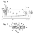
- Fig. 4 and 5 show a bottom view of the baseplate 1 and a cross section of it in a non-locking configuration.
- the latch 9 is pressed into the baseplate 1, so that pin 11 is hidden within the wedge 5.
- the cog 12 is held pressed into the notch 24 by a compressed helical spring 25.
- Another helical spring 26 is mounted in a cutout 27 and is under a torsion load, so that an end branch 28 of spring 26 applies a force to a catch 29 of latch 9 which tends to push latch 9 out of the baseplate 1.
- the latch 9, being blocked by cog 12, cannot yield to this force.
- a two-armed lever 31 is rotatably held on a shaft 32.
- a wedge 34 is pressed against one end of the lever 31 by a third helical spring 33, whereby the other end of the lever 31 is pressed against the inner end of latch 9.
- the wedge 34 has a longitudinal slot 35 formed in it, through which the stem 20 extends.
- a pressing plate 36 extending across the wedge 34 is fixed to an end of the stem 20.
- a leaf spring 37 which is not shown in Fig. 4 for the sake of clarity, but in Fig. 5 only, urges the plate 36 against the wedge 34, so that the wedge 34 is held without play between the plate 36 and an inner surface of baseplate 1.
- the space 38 between the upper surface of baseplate 1 and the bottom side of locking plate 19 is wide enough for the webs 23 of shoe plate 21 to engage in it easily.
- the resulting configuration can be seen in Figs. 2 and 3 .
- the wedge 34 yields to the force of spring 33, until the locking plate 19 is drawn so close to the baseplate 1 that the webs 23 of shoe plate 21 are clamped between baseplate 1 and locking plate 19. Since the slope of the wedge 34 is small - the thickness difference between its thick and narrow ends may be less than 0.5 mm, whereas the distance between its two positions in the configurations of Fig. 2 and 4 may be several millimetres the wedge 34 cannot slide sideways if a pulling force is applied to the locking plate 19, so that the shoe plate 21 is held firmly and without play.
- a camera support of this kind can be used advantageously for a a camera assembly, in particular for a superexpander as described before, which will be explaned now in the following figures.
- reference numeral 100 denotes a camera support having a first, substantially vertical branch 4 and a second, substantially horizontal branch 101.
- the vertical branch 4 extends perpendicular to the optical axis A of a lens 102 which is mounted to an outer side of branch 4.
- the horizontal branch 101 comprises a first generally plate-shaped member 103 which is rigidly connected to the vertical branch 4 and is provided with a fixture for fixing it to a tripod or the like, and which is therefore referred to as an immobile member, and a second generally plate-shaped member 1 on which a camera body 104 is mounted. In a first position of the camera body 104 and the second plate-shaped member 1 represented by solid lines in Fig.
- Figs. 7 to 11 The plate-shaped member 1 of Fig. 7 corresponds with the baseplate 1 as explained already with regard to Fig. 1 - 5 .
- identical reference numerals are used.
- the displaceable member 1 is a flat slab made of aluminum or the like, a front end 2 of which faces the vertical branch 4. Near the front end 2, two wedges 5 are formed on the displaceable member 1.
- the wedges 5 have vertical outer sides 6 extending in a longitudinal direction of the displaceable member 1 and inner sides 7 which face each other and converge in upward and frontward directions, so as to define a wide tapered groove 8 having a swallow-tail cross section.
- a latch 9 is slideably received in a transversal slot of the displaceable member 1.
- a head is formed which has a concave surface 10, which is easily pressed with a finger, in order to push the latch 9 into the displaceable member 1.
- the head further has a downward-projecting portion 39, which co-operates with a projection 124 of immobile member 103 in a way which will become apparent later in the description.
- the latch 9 is connected to a cylindrical pin 11 which protrudes through an elongated hole 13 at the bottom of tapered groove 8. The elongated hole 13 extends into one of the wedges 5, so that when the latch 9 is pressed, the pin 11 moves out of the groove 8 and disappears in the opening of the wedge.
- a trigger pawl 14 Adjacent to the outer side 6 of one of the wedges 5, a trigger pawl 14 is mounted in a hole 15 of the displaceable member 1.
- the trigger pawl 14 is displaceable in the longitudinal direction of the displaceable member 1.
- a cuboid block 16 is shown, which forms engaging means of the camera body 104.
- the camera body 104 is shown in phantom in Fig. 7 in order to illustrate its position with respect to the block 16.
- two tapered grooves 17 are formed, the shape of which matches the wedges 5 of the displaceable member 1. Since the grooves 17 have wide openings at the side of the block 16 which faces the wedges 5, it is easy to make the wedges 5 engage the grooves 17 when the camera body 104 is pushed towards the wall 4 in order to prepare for coupling it to the lens 102.
- the camera body 104 can be pushed forward until an abutment position is reached in which the inner sides of the groove 17 touch the inner sides 7 of the wedges 5.
- a notch 18 formed in an inner side of one of the grooves 17 is aligned with the elongated hole 13, so that pin 11 can engage it and come into contact with a front wall of the notch 18, thereby preventing a rearward movement of the block 16.
- the block 16 is thus locked to the displaceable member 1 without any play.
- a circular locking plate 19 is held spaced from the upper side of the baseplate 1 by a cylindrical stem 20 (see e. g. Fig. 11 ) which, in the view of Fig. 7 , is concealed completely below the locking plate 19.
- the camera body 104 has a shoe plate 21 fixed to its rear bottom portion, in which an undercut groove 22 is formed.
- the groove 22 In its upper portion, the groove 22 is wide enough to receive the locking plate 19, whereas in a lower portion thereof, webs 23 protrude from the sides of the groove towards the centre in order to engage between the locking plate 19 and the surface of the displaceable member 1 at both sides of the stem 20.
- the camera body 104 would be locked to the displaceable member 1, if it was appropriately placed with its block 16 engaging the groove 8, the pin 11 engaging the notch 18 and the locking plate 19 engaging the groove 22 of shoe plate 21.
- Fig. 9 and 10 show a bottom view of the displaceable member 1 and a cross section of it in a non-locking configuration.
- the latch 9 is pressed into the displaceable member 1, so that pin 11 is hidden within the wedge 5 .
- the cog 12 is held pressed into the notch 24 by a compressed helical spring 25.
- Another helical spring 26 is mounted in a cutout 27 and is under a torsion load, so that an end branch 28 of spring 26 applies a force to a catch 29 of latch 9 which tends to push latch 9 out of the baseplate 1.
- a two-armed lever 31 is rotatably held on a shaft 32.
- a wedge 34 is pressed against one end of the lever 31 by a third helical spring 33, whereby the other end of the lever 31 is pressed against the inner end of latch 9.
- the wedge 34 has a longitudinal slot 35 formed in it, through which the stem 20 extends.
- a pressing plate 36 extending across the wedge 34 is fixed to an end of the stem 20.
- a leaf spring 37 which is not shown in Fig. 10 for the sake of clarity, but in Fig. 11 only, urges the plate 36 against the wedge 34, so that the wedge 34 is held without play between the plate 36 and an inner surface of displaceable member 1.
- the space 38 between the upper surface of displaceable member 1 and the bottom side of locking plate 19 is wide enough for the webs 23 of shoe plate 21 to engage in it easily.
- the resulting configuration can be seen in Fig. 8 and 9 .
- the wedge 34 yields to the force of spring 33, until the locking plate 19 is drawn so close to the displaceable member 1 that the webs 23 of shoe plate 21 are clamped between displaceable member 1 and locking plate 19. Since the slope of the wedge 34 is small - the thickness difference between its thick and narrow ends may be less than 0.5 mm, whereas the distance between its two positions in the configurations of Fig. 8 and 10 may be several millimetres - the wedge 34 cannot slide sideways if a pulling force is applied to the locking plate 19, so that the shoe plate 21 is held firmly and without play.
- the displaceable member 1 is connected to the immobile member 103 by means of a screw 107 which extends through an elongated hole 108 of displaceable member 1 and engages a threaded bore of immobile member 103.
- FIG. 11 Other connecting means for connecting and locking the displaceable member 1 to immobile member 103, as shown e.g. in Fig. 11 , comprise a locking plate 109 similar to locking plate 19 but held spaced from the bottom side of displaceable member 1 by a stem 110. Similar to stem 20, stem 110 extends through a hole of a wedge 111. The wedge is connected to a latch 112 which extends out of the displaceable member 1. In the configuration of Figs. 8 and 10 , the latch 112 is locked in position by a spring-loaded pawl 113 which engages a notch of latch 112 and thus prevents a spring 114 from expanding and pushing the latch 112 outwards.
- a spring-loaded pawl 113 which engages a notch of latch 112 and thus prevents a spring 114 from expanding and pushing the latch 112 outwards.
- the bottom view of displaceable member 1 in Fig. 12 shows a shallow recess 115 formed in the bottom side of the displaceable member 1.
- a trigger portion of pawl 113 extends through an opening at the bottom of the recess 115.
- a locking pin 122 connected to latch 112 protrudes into recess 115 through a slot which extends in the direction of displacement of latch 112.
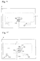
- Fig. 13 is a top view of the immobile member 103 with the outline of displaceable member 1 shown in phantom.
- a shoe plate 116 similar to shoe plate 21 of the camera body is fixed to the upper side of immobile member 103.
- the displaceable member 1 is lying loosely on top of the immobile member 103, and the locking plate 109 of displaceable member 1 is inserted from above into a circular cutout at an end of a groove 117 of shoe plate 116.
- Undercuts 123 of groove 117 are represented by dash-dot-lines.
- the block is urged to a side of immobile member 103 by a compression spring 120.
- a compression spring 120 In the configuration of Fig. 13 , the screw 107 is removed, and elongated hole 108 does not coincide with the threaded bore 121 of immobile member which the screw 107 is to engage.
- the camera body is not yet connected to the displaceable member 1.
- the configuration of Fig. 13 is a service configuration in which the displaceable member 1 can be freely placed on or removed from immobile member 103.
- displaceable member 1 After placing the displaceable member 1 on immobile member 103 in the configuration of Fig. 13 , displaceable member 1 is pushed towards the vertical member 4. As can be seen in Fig. 14 , the block 119 is displaced against the force of spring 120 by sliding along a tapered side of the trigger portion of pawl 113. The pawl 113 is not displaced by block 119.
- the latch 9 is pressed into the displaceable member 1, whereby, as explained above, pin 11 is moved out of swallow-tail groove 8, thus clearing the groove 8 for engaging the cuboid block 16 of camera body 104.
- pin 11 is moved out of swallow-tail groove 8, thus clearing the groove 8 for engaging the cuboid block 16 of camera body 104.
- the latch 9 when the latch 9 is pressed in, its downward-projecting portion 39 would abut against projection 124 if the displaceable member 1 was pushed forward. I. e. when the displaceable member 1 is ready for receiving the camera body 104, it cannot be pushed close to the vertical member 4, and an accidental collision of the camera body 104 and the lens 102 is prevented.
- the latch 9 comes out of the displaceable member 1 again, and the camera assembly is in the first position described above with respect to Fig. 6 .
- the latch 9 does not interfere with projection 124 any more now, but the displaceable member 1 is still locked to the immobile member 103.
- the camera body 104 and the camera support 100 can conveniently be handled as a unit; e.g. they may be removed from a tripod and placed in a storage box together for transport.
- displaceable member 1 By pressing inward the latch 112, displaceable member 1 is unlocked from immobile member 103, so that the displaceable member 1 and the camera body 104 supported by it can be pushed forward into the position of Fig. 19 , in which the camera body 104 is close enough to the lens 102 for the bayonet coupling 105, 106 to be locked.
- This is the second position mentioned above with respect to Fig. 6 .
- the projection 124 is below the latch 9, so that the latch 9 cannot be pushed inwards.
- Fig. 20 is a perspective view, analogous to Fig. 7 , of a camera support according to a second embodiment of the invention. Components of this embodiment which correspond to those of the embodiment of Fig. 7 have identical reference numerals.
- Fig. 20 differs from that of Fig. 7 in that the displaceable member 1 does not rest directly on immobile member 103, but there is a plate 125 between the two.
- Plate 125 rests directly on immobile member 103 and is connected to displaceable member 1 by a shaft 126, allowing the displaceable member 1 to be tilted by a few degrees with respect to the immobile member 103.
- the plate 125 has a central opening, not shown in the Fig, through which stem 110 extends, allowing the assembly formed of displaceable member 1 and plate 125 to be mounted on immobile member 103 just as described above referring to Figs 13 to 19 .
- a spring is concealed between plate 125 and displaceable member 1 for urging the rear portion of displaceable member 1 upward, compensating the weight of the camera body, so that the tilt of the camera body can be changed with little effort.
- a second screw 127 similar to screw 107 is provided for locking the displaceable member 1 with respect to the plate 125 at a desired tilt angle.
- the screw 127 may be unlocked, allowing the camera body to yield to any torque that might occur between the bayonet coupling members 105, 106 during locking, so that once the screw 127 is locked again, the assembly is free from internal stress.
Landscapes
- Engineering & Computer Science (AREA)
- General Engineering & Computer Science (AREA)
- Mechanical Engineering (AREA)
- Multimedia (AREA)
- Signal Processing (AREA)
- Structure And Mechanism Of Cameras (AREA)
- Accessories Of Cameras (AREA)
- Studio Devices (AREA)
Description
- The present invention relates to a camera support for releasably mounting a camera, and a respective camera assembly. A known camera assembly in the field of television cameras is a so-called superexpander, which may be regarded as a kind of frame for mounting on a tripod or the like, and which bears a lens, and to which different types of camera bodies may be releasably connected in order to cooperate with the lens.
- A prior art super-expander comprises two orthogonal branches, a first one of which extends perpendicular to an optical axis of a lens mounted to it, and the second of which extends at a side of the first branch opposite to the side at which the lens is mounted and to which the camera body is releasably locked.
- Conventionally, such a superexpander has a baseplate on which first and second engaging means are formed for releasably engaging front and rear portions of a camera body, and the camera body is displaceable from rear to front on the baseplate in order to be connected. The first engaging means (or front engaging means) is formed of two wedges, which define the sides of a tapered swallowtail groove, and which converge in the forward direction. The camera body has a tapered wedge of swallowtail cross section which may be pushed into said groove until the sides of the camera wedge touch those of the baseplate. In this way, an abutment position for the camera body is defined, beyond which it cannot move forward, and where it cannot move laterally or vertically, either. The second or rear engaging means are formed by a platelet which is held by a stem at a distance from the baseplate, and complementary engaging means of the camera comprise webs which engage between the baseplate and the platelet when the camera body is moved forward to its abutment position.
- There must be some play between the platelet and the webs, in order to ensure that they can be freely engaged and disengaged. However, this play implies that there is some residual mobility in the rear portion of the camera body, even if the front portion thereof is in the abutment position. If the camera body can move with respect to the lens, so will the image projected by the lens with respect to the light sensitive surface of the camera body. In order to avoid this, a play-free fixture must be provided for the rear portion of the camera, too. Of course, additional tools might be provided for fixing the rear portion of the camera to the baseplate without play, but operating these tools is tedious, and there is a risk that the camera man forgets to use them.
- Further, there is a risk of damaging the lens if the camera body is pushed towards the abutment position without being properly oriented with respect to the optical axis.
- The object of the invention is to provide a camera support and a camera assembly which will lock a camera body in place without play automatically when it is moved into its intended mounting position, and which allows in particular a safe handling of the camera body with regard to the lens.
- This object is achieved by a camera support comprising a baseplate on which first and second engaging means are formed for releasably engaging first and second portions of a camera body displaced along the baseplate in an engaging direction, wherein the first engaging means defines an abutment position for the first region of the camera, and the second engaging means defines a space between two sidewalls for slidably receiving a web of the camera, and wherein one of said sidewalls is displaceable towards the other and is coupled to a trigger of the first engaging means so as to clamp the web between the sidewalls when the trigger is operated by the first region reaching the abutment position.
- The camera support preferably comprises a first spring for urging the sidewalls away from each other, so that the web of the camera may be freely introduced into the space between them as long as the trigger is not operated.
- One of said sidewalls may be formed by a flat outside surface of said baseplate, and the other sidewall may be formed by a locking plate which is held above said flat surface by a stem extending through a bore of said flat surface.
- In order to drive the clamping movement, a wedge may be located between a pressing surface of said stem and an inside surface of said baseplate, so that when the wedge is thrust farther into the space between the pressing surface and the inside surface of the baseplate, the locking plate is pulled towards the outside surface of the baseplate.
- In order to apply a well balanced pulling force to the stem, the stem may extend through a slot of the wedge, and the pressing surface may be formed on a plate that extends sideways from said stem.
- A second spring may be provided for urging the wedge towards a position in which the stem is withdrawn into the baseplate, so that no external driving force is required for withdrawing the stem.
- For coupling the wedge to the trigger of the first engaging means, the wedge is preferably arranged to be displaceable transversally with respect to the displacement direction of the camera body, and the trigger releasably engages a spring-loaded latch, which is also displaceable transversally with respect to the displacement direction, and the wedge is coupled to the latch by a two-armed lever extending in the displacement direction.
- A camera support of this kind can be used advantageously for a respective camera assembly. The camera assembly comprises a camera support with two orthogonal branches, a first of which is adapted to support a lens, and a second of which has first locking means for releasably locking a camera body to the second branch, in which said second branch has an immobile member with respect to the first branch and a displaceable member which is displaceable with respect to the immobile member along a predefined trajectory, said first locking means are formed in said displaceable member which is displaceable between a first position in which said camera body, when locked to the displaceable member by said first locking means, is spaced from the lens, and a second position in which the camera body connects to the lens. The displaceable member corresponds with the baseplate of the camera support, as described before.
- Since in this camera assembly, the camera body is locked to the support while the displaceable member is in its first position, there is no risk of contact between the camera body and a lens which may be mounted to the first branch, even if the camera is pushed violently towards its abutment position without being properly oriented. There is no risk that the abutment position cannot be reached because due to manufacturing tolerances the camera body hits the first branch before, or that the bayonet connection is difficult to close because the camera body in the abutment position is too far apart from the first branch.
- As a first safety measure, it can be provided that the displaceable member is displaceable into the second position only if the locking means is in a locking configuration. Thus the camera body can approach the lens only if its orientation is correct, and there is no risk of a contact between the camera body and an optical surface of the lens.
- This first safety measure may in particular be embodied by an operating member of said locking means which is displaceable perpendicular to the displacement direction of said displaceable member and which may be displaced by a user for locking and/or unlocking the camera body, and by said immobile member having a projection which blocks the operating member in its locking configuration when the displaceable member is in the second position.
- As a second safety measure, it can be provided that the locking means is locked in the locking configuration when the displaceable member is in the second position. I.e. the camera body cannot be unlocked from the displaceable member while it is so close to the lens that an accidental movement of the camera body might damage the lens.
- This first safety measure may in particular be embodied by an operating member of said locking means which is displaceable perpendicular to the displacement direction of said displaceable member and which may be displaced by a user for locking and/or unlocking the camera body, and by said immobile member having a projection which blocks the displaceable member in its first position when the locking means is in a non-locking configuration.
- It is particularly preferred that both safety measures be implemented, and that the operating member and the projection of the two safety measures be the same. This may be achieved e.g. by providing the operating member with a first blocking surface which extends substantially perpendicular to the displacement direction of the displaceable member, which faces a first side of the projection of the immobile member while in the non-locking configuration and which does not overlap said first blocking surface when the operating member is in the locking configuration, and with a second blocking surface which is substantially perpendicular to the direction of displacement of said operating member between its locking and non-locking configurations, and which overlaps with a second side of said projection only if the displaceable member is in its second position.
- The camera body and the displaceable member should preferably have co-operating guide means for guiding the camera body into a position in which the locking means are capable of locking the camera body to the displaceable member. These co-operating guide means may comprise a tapered wedge and a mating tapered swallow-tail groove, one of which is located at the camera body and the other of which is located at the displaceable member, e.g. as described above. In addition or as an alternative, co-operating webs and grooves of constant width may be provided at the displaceable member and at the camera body, for strictly guiding a linear displacement of the camera body with respect to the support.
- The guide means may guide the camera body into its locking position in parallel to the displacement direction of the displaceable member; since according to the above safety measures the displaceable member is blocked while in the non-locking configuration, there is no risk of the camera body hitting the lens without being properly locked, and, hence, properly oriented.
- The displaceable member may be displaceable into a third position in which it farther away from the first branch than in the first and second positions, and in which it is unlocked from the immobile member. In this position, it is possible to remove the displaceable member from the support, e.g. for repair or maintenance purposes.
- Second locking means may be provided for automatically and releasably locking the displaceable member to the immobile member when the displaceable member is displaced from its first position to its second position, thus preventing the camera body from coming closer to the lens than necessary for connecting the two.
- The camera assembly allows therefore to lock the camera body to the support in a well-defined position and to connect the camera body to the lens without having to impose too strict tolerances on placing and dimensions of the various components that co-operate in the connection between camera body and lens. There is further no risk of damaging the lens when the camera body is approached to it.
- Further features and advantages of the invention will become apparent from the subsequent description of embodiments thereof, referring to the appended drawings.
- Fig. 1
- is a perspective view of a camera support and of complementary engaging means of a camera for cooperating with the engaging means of the camera support;
- Fig. 2
- is a bottom view of the support of
Fig. 1 ; - Fig. 3
- is a cross section of the support taken along line III-III of
Fig. 2 ; - Fig. 4
- is a bottom view of the mounting plate in unlocked configuration;
- Fig. 5
- is a cross section along line V-V of
Fig. 4 ; - Fig. 6
- is a schematic side view of a camera assembly comprising a camera support as shown in
Figs. 1 - 5 ; - Fig. 7
- is a perspective view of a baseplate as shown in
Fig. 1 , arranged as a displaceable member of the camera assembly ofFig. 6 and of complementary engaging means of the camera for cooperating with the engaging means of the displaceable member; - Fig. 8
- is a horizontal section of the displaceable member of
Fig. 7 along line III-III ofFig. 9 ; - Fig. 9
- is a cross section of the displaceable member taken along line IV-IV of
Fig. 8 ; - Fig. 10
- is a horizontal section of the displaceable member in unlocked configuration along line V-V of
Fig. 11 ; and - Fig. 11
- is a cross section along line VI-VI of
Fig. 10 ; - Fig. 12
- is a bottom view of the displaceable member;
- Figs. 13 to 19
- show steps of a mounting procedure of the camera assembly; and
- Fig. 20
- is a perspective view, analogous to
Fig. 7 , of a camera support according to a second embodiment of a camera assembly. - The general configuration of the camera support will be explained referring to
Fig. 1 . Like a conventional superexpander, the support comprises abaseplate 1 and avertical wall 4 which is faced by afront end 2 ofbaseplate 1 and to an upper portion of which a lens, not shown, is mounted. In theFig.1 , only a lower portion ofwall 4 is depicted. Thebaseplate 1 is a flat slab made of aluminum or the like. - Near the
front end 2, twowedges 5 are formed on thebaseplate 1. Thewedges 5 have verticalouter sides 6 extending in a longitudinal direction of thebaseplate 1 andinner sides 7 which face each other and converge in upward and frontward directions, so as to define a wide taperedgroove 8 having a swallow-tail cross section. - Underneath the
wedges 5, alatch 9 is slideably received in a transversal slot of thebaseplate 1. At a remote end of thelatch 9, aconcave surface 10 is formed, which is easily pressed with a finger, in order to push thelatch 9 into thebaseplate 1. Thelatch 9 is connected to acylindrical pin 11 which protrudes through anelongated hole 13 at the bottom of taperedgroove 8. Theelongated hole 13 extends into one of thewedges 5, so that when thelatch 9 is pressed, thepin 11 moves out of thegroove 8 and disappears in the opening of the wedge. - Adjacent to the
outer side 6 of one of thewedges 5, atrigger pawl 14 is mounted in ahole 15 of thebaseplate 1. Thetrigger pawl 14 is displaceable in the longitudinal direction of thebaseplate 1. - Near the centre of the
baseplate 1, acuboid block 16 is shown, which forms engaging means of the camera body. The camera body is shown in phantom in the figure in order to illustrate its position with respect to theblock 16. At the bottom side of theblock 16, twotapered grooves 17 are formed, the shape of which matches thewedges 5 of the baseplate. Since thegrooves 17 have wide openings at the side of theblock 16 which faces thewedges 5, it is easy to make thewedges 5 engage thegrooves 17 when the camera body is pushed towards thewall 4 in order to prepare for coupling it to the lens. The camera body can be pushed forward until an abutment position is reached in which the inner sides of thegroove 17 touch theinner sides 7 of thewedges 5. When this happens, anotch 18 formed in an inner side of one of thegrooves 17 is aligned with theelongated hole 13, so thatpin 11 can engage it and come into contact with a front wall of thenotch 18, thereby preventing a rearward movement of theblock 16. The position ofblock 16 is thus defined without any play. - Near the
rear end 3 of thebaseplate 1, acircular locking plate 19 is held spaced from the upper side of thebaseplate 1 by a cylindrical stem 20 (see e. g.Fig. 5 ) which, in the view ofFig. 1 , is concealed completely below the lockingplate 19. - The camera body has a
shoe plate 21 fixed to its rear bottom portion, in which an undercutgroove 22 is formed. In its upper portion, thegroove 22 is wide enough to receive the lockingplate 19, whereas in a lower portion thereof,webs 23 protrude from the sides of the groove towards the centre in order to engage between the lockingplate 19 and the surface of thebaseplate 1 at both sides of thestem 20. - In the configuration of the support shown in
Fig. 1 , a camera body would be locked to the support, if appropriately placed with itsblock 16 engaging thegroove 8, thepin 11 engaging thenotch 18 and the lockingplate 19 engaging thegroove 22 ofshoe plate 21. - In order to understand the process of locking the camera body to the support, reference will now be made to
Fig. 4 and 5 , which show a bottom view of thebaseplate 1 and a cross section of it in a non-locking configuration. In this configuration, thelatch 9 is pressed into thebaseplate 1, so thatpin 11 is hidden within thewedge 5. Acog 12, which is part oftrigger pawl 14, engages anotch 24 oflatch 9. Thecog 12 is held pressed into thenotch 24 by a compressedhelical spring 25. Another helical spring 26 is mounted in acutout 27 and is under a torsion load, so that anend branch 28 of spring 26 applies a force to acatch 29 oflatch 9 which tends to pushlatch 9 out of thebaseplate 1. Thelatch 9, being blocked bycog 12, cannot yield to this force. - In a
longitudinal cutout 30 of thebaseplate 1, a two-armed lever 31 is rotatably held on ashaft 32. Awedge 34 is pressed against one end of thelever 31 by a thirdhelical spring 33, whereby the other end of thelever 31 is pressed against the inner end oflatch 9. Thewedge 34 has alongitudinal slot 35 formed in it, through which thestem 20 extends. Apressing plate 36 extending across thewedge 34 is fixed to an end of thestem 20. Aleaf spring 37, which is not shown inFig. 4 for the sake of clarity, but inFig. 5 only, urges theplate 36 against thewedge 34, so that thewedge 34 is held without play between theplate 36 and an inner surface ofbaseplate 1. In the configuration ofFig. 5 , thespace 38 between the upper surface ofbaseplate 1 and the bottom side of lockingplate 19 is wide enough for thewebs 23 ofshoe plate 21 to engage in it easily. - In the process of pushing the camera body forward from the position shown in
Fig. 1 to the position in which it is to be locked, theblock 16 hits triggerpawl 14 and pushes it towardsfront end 2, wherebyspring 25 is compressed andcog 12 is removed fromnotch 24. Now, thelatch 9 can yield to the force of spring 26 and move outward. Thelever 31 is now free to rotate aboutshaft 32, so that it yields to the pressure of thewedge 34, thewedge 34 is moved downward in the perspective ofFig. 4 or to the right in the perspective ofFig. 5 , thus pulling lockingplate 19 towardsbaseplate 1. - The resulting configuration can be seen in
Figs. 2 and 3 . Thewedge 34 yields to the force ofspring 33, until the lockingplate 19 is drawn so close to thebaseplate 1 that thewebs 23 ofshoe plate 21 are clamped betweenbaseplate 1 and lockingplate 19. Since the slope of thewedge 34 is small - the thickness difference between its thick and narrow ends may be less than 0.5 mm, whereas the distance between its two positions in the configurations ofFig. 2 and4 may be several millimetres thewedge 34 cannot slide sideways if a pulling force is applied to the lockingplate 19, so that theshoe plate 21 is held firmly and without play. - In order to release the camera body again, it is sufficient to press the
latch 9 into thebaseplate 1, so thatpin 11 moves out ofgroove 8 and into itswedge 5, and thewedge 34 is pushed back bylever 13, allowing the lockingplate 19 to be raised byleaf spring 37. The camera body is thus unlocked and can be drawn backwards. Due to thecog 12 being pressed intonotch 24 byspring 25, thelatch 9 is held in this position until another camera body is mounted and presses triggerpawl 14 forward again. - A camera support of this kind can be used advantageously for a a camera assembly, in particular for a superexpander as described before, which will be explaned now in the following figures.
- In the side view of the camera assembly of
Fig. 6 ,reference numeral 100 denotes a camera support having a first, substantiallyvertical branch 4 and a second, substantiallyhorizontal branch 101. Thevertical branch 4 extends perpendicular to the optical axis A of alens 102 which is mounted to an outer side ofbranch 4. Thehorizontal branch 101 comprises a first generally plate-shapedmember 103 which is rigidly connected to thevertical branch 4 and is provided with a fixture for fixing it to a tripod or the like, and which is therefore referred to as an immobile member, and a second generally plate-shapedmember 1 on which acamera body 104 is mounted. In a first position of thecamera body 104 and the second plate-shapedmember 1 represented by solid lines inFig. 6 , there is a space between thecamera body 104 and thevertical branch 4, andbayonet coupling members lens 102 andcamera body 104 do not engage. The second plate-shapedmember 1 is displaceable into a second position, shown in phantom inFig. 6 , in whichcoupling members bayonet coupling members - In order to facilitate an understanding of the camera assembly and its operation, to begin with, the second and its connection to the
camera body 104 will now be explained in detail referring toFigs. 7 to 11 . The plate-shapedmember 1 ofFig. 7 corresponds with thebaseplate 1 as explained already with regard toFig. 1 - 5 . For same components identical reference numerals are used. - As shown in
Fig. 7 , thedisplaceable member 1 is a flat slab made of aluminum or the like, afront end 2 of which faces thevertical branch 4. Near thefront end 2, twowedges 5 are formed on thedisplaceable member 1. Thewedges 5 have verticalouter sides 6 extending in a longitudinal direction of thedisplaceable member 1 andinner sides 7 which face each other and converge in upward and frontward directions, so as to define a wide taperedgroove 8 having a swallow-tail cross section. - Underneath the
wedges 5, alatch 9 is slideably received in a transversal slot of thedisplaceable member 1. At a remote end of thelatch 9, a head is formed which has aconcave surface 10, which is easily pressed with a finger, in order to push thelatch 9 into thedisplaceable member 1. The head further has a downward-projectingportion 39, which co-operates with aprojection 124 ofimmobile member 103 in a way which will become apparent later in the description. Thelatch 9 is connected to acylindrical pin 11 which protrudes through anelongated hole 13 at the bottom of taperedgroove 8. Theelongated hole 13 extends into one of thewedges 5, so that when thelatch 9 is pressed, thepin 11 moves out of thegroove 8 and disappears in the opening of the wedge. - Adjacent to the
outer side 6 of one of thewedges 5, atrigger pawl 14 is mounted in ahole 15 of thedisplaceable member 1. Thetrigger pawl 14 is displaceable in the longitudinal direction of thedisplaceable member 1. - Near the centre of the
displaceable member 1, acuboid block 16 is shown, which forms engaging means of thecamera body 104. Thecamera body 104 is shown in phantom inFig. 7 in order to illustrate its position with respect to theblock 16. At the bottom side of theblock 16, twotapered grooves 17 are formed, the shape of which matches thewedges 5 of thedisplaceable member 1. Since thegrooves 17 have wide openings at the side of theblock 16 which faces thewedges 5, it is easy to make thewedges 5 engage thegrooves 17 when thecamera body 104 is pushed towards thewall 4 in order to prepare for coupling it to thelens 102. Thecamera body 104 can be pushed forward until an abutment position is reached in which the inner sides of thegroove 17 touch theinner sides 7 of thewedges 5. When this happens, anotch 18 formed in an inner side of one of thegrooves 17 is aligned with theelongated hole 13, so thatpin 11 can engage it and come into contact with a front wall of thenotch 18, thereby preventing a rearward movement of theblock 16. Theblock 16 is thus locked to thedisplaceable member 1 without any play. - Near the
rear end 3 of thedisplaceable member 1, acircular locking plate 19 is held spaced from the upper side of thebaseplate 1 by a cylindrical stem 20 (see e. g.Fig. 11 ) which, in the view ofFig. 7 , is concealed completely below the lockingplate 19. - The
camera body 104 has ashoe plate 21 fixed to its rear bottom portion, in which an undercutgroove 22 is formed. In its upper portion, thegroove 22 is wide enough to receive the lockingplate 19, whereas in a lower portion thereof,webs 23 protrude from the sides of the groove towards the centre in order to engage between the lockingplate 19 and the surface of thedisplaceable member 1 at both sides of thestem 20. - In the configuration of the
displaceable member 1 shown inFig. 7 , thecamera body 104 would be locked to thedisplaceable member 1, if it was appropriately placed with itsblock 16 engaging thegroove 8, thepin 11 engaging thenotch 18 and the lockingplate 19 engaging thegroove 22 ofshoe plate 21. - In order to understand the process of locking the camera body to the
displaceable member 1, reference will now be made toFig. 9 and10 , which show a bottom view of thedisplaceable member 1 and a cross section of it in a non-locking configuration. In this configuration, thelatch 9 is pressed into thedisplaceable member 1, so thatpin 11 is hidden within thewedge 5 . Acog 12, which is part oftrigger pawl 14, engages anotch 24 oflatch 9. Thecog 12 is held pressed into thenotch 24 by a compressedhelical spring 25. Another helical spring 26 is mounted in acutout 27 and is under a torsion load, so that anend branch 28 of spring 26 applies a force to acatch 29 oflatch 9 which tends to pushlatch 9 out of thebaseplate 1. Thelatch 9, being blocked bycog 12, cannot yield to this force. - In a
longitudinal cutout 30 of thedisplaceable member 1, a two-armed lever 31 is rotatably held on ashaft 32. Awedge 34 is pressed against one end of thelever 31 by a thirdhelical spring 33, whereby the other end of thelever 31 is pressed against the inner end oflatch 9. Thewedge 34 has alongitudinal slot 35 formed in it, through which thestem 20 extends. Apressing plate 36 extending across thewedge 34 is fixed to an end of thestem 20. Aleaf spring 37, which is not shown inFig. 10 for the sake of clarity, but inFig. 11 only, urges theplate 36 against thewedge 34, so that thewedge 34 is held without play between theplate 36 and an inner surface ofdisplaceable member 1. In the configuration ofFig. 11 , thespace 38 between the upper surface ofdisplaceable member 1 and the bottom side of lockingplate 19 is wide enough for thewebs 23 ofshoe plate 21 to engage in it easily. - In the process of pushing the
camera body 104 forward from the position shown inFig. 7 to the position in which it is to be locked to thedisplaceable member 1, theblock 16 hits triggerpawl 14 and pushes it towardsfront end 2, wherebyspring 25 is compressed andcog 12 is removed fromnotch 24. Now, thelatch 9 can yield to the force of spring 26 and move outward. Thelever 31 is now free to rotate aboutshaft 32, so that it yields to the pressure of thewedge 34, thewedge 34 is moved downward in the perspective ofFig. 10 or to the right in the perspective ofFig. 11 , thus pulling lockingplate 19 towardsdisplaceable member 1. - The resulting configuration can be seen in
Fig. 8 and 9 . Thewedge 34 yields to the force ofspring 33, until the lockingplate 19 is drawn so close to thedisplaceable member 1 that thewebs 23 ofshoe plate 21 are clamped betweendisplaceable member 1 and lockingplate 19. Since the slope of thewedge 34 is small - the thickness difference between its thick and narrow ends may be less than 0.5 mm, whereas the distance between its two positions in the configurations ofFig. 8 and10 may be several millimetres - thewedge 34 cannot slide sideways if a pulling force is applied to the lockingplate 19, so that theshoe plate 21 is held firmly and without play. - In order to release the camera body again, it is sufficient to press the
latch 9 into thedisplaceable member 1, so thatpin 11 moves out ofgroove 8 and into itswedge 5, and thewedge 34 is pushed back bylever 31, allowing the lockingplate 19 to be raised byleaf spring 37. Thecamera body 104 is thus unlocked and can be drawn backwards. Due to thecog 12 being pressed intonotch 24 byspring 25, thelatch 9 is held in this position until another camera body is mounted and presses triggerpawl 14 forward again. - Referring to
Fig. 7 again, thedisplaceable member 1 is connected to theimmobile member 103 by means of ascrew 107 which extends through anelongated hole 108 ofdisplaceable member 1 and engages a threaded bore ofimmobile member 103. - Other connecting means for connecting and locking the
displaceable member 1 toimmobile member 103, as shown e.g. inFig. 11 , comprise alocking plate 109 similar to lockingplate 19 but held spaced from the bottom side ofdisplaceable member 1 by astem 110. Similar to stem 20, stem 110 extends through a hole of awedge 111. The wedge is connected to alatch 112 which extends out of thedisplaceable member 1. In the configuration ofFigs. 8 and10 , thelatch 112 is locked in position by a spring-loadedpawl 113 which engages a notch oflatch 112 and thus prevents aspring 114 from expanding and pushing thelatch 112 outwards. - The bottom view of
displaceable member 1 inFig. 12 shows ashallow recess 115 formed in the bottom side of thedisplaceable member 1. A trigger portion ofpawl 113 extends through an opening at the bottom of therecess 115. By displacing the trigger portion to the left inFig. 12 , thepawl 113 is disengaged from the notch oflatch 112; thelatch 112 is thrust outward, and thelocking plate 109 is drawn towards the bottom side of displaceable member bywedge 111. - A locking
pin 122 connected to latch 112 protrudes intorecess 115 through a slot which extends in the direction of displacement oflatch 112. - Referring to
Figs. 13 to 19 , the assembling procedure of the camera assembly is explained. -
Fig. 13 is a top view of theimmobile member 103 with the outline ofdisplaceable member 1 shown in phantom. Ashoe plate 116 similar toshoe plate 21 of the camera body is fixed to the upper side ofimmobile member 103. Thedisplaceable member 1 is lying loosely on top of theimmobile member 103, and thelocking plate 109 ofdisplaceable member 1 is inserted from above into a circular cutout at an end of agroove 117 ofshoe plate 116.Undercuts 123 ofgroove 117 are represented by dash-dot-lines. At a side ofshoe plate 116, there is a T-shapedgroove 118 from the bottom of which adisplaceable block 119 projects upward. The block is urged to a side ofimmobile member 103 by acompression spring 120. In the configuration ofFig. 13 , thescrew 107 is removed, andelongated hole 108 does not coincide with the threaded bore 121 of immobile member which thescrew 107 is to engage. The camera body is not yet connected to thedisplaceable member 1. The configuration ofFig. 13 is a service configuration in which thedisplaceable member 1 can be freely placed on or removed fromimmobile member 103. - After placing the
displaceable member 1 onimmobile member 103 in the configuration ofFig. 13 ,displaceable member 1 is pushed towards thevertical member 4. As can be seen inFig. 14 , theblock 119 is displaced against the force ofspring 120 by sliding along a tapered side of the trigger portion ofpawl 113. Thepawl 113 is not displaced byblock 119. - When the
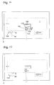
displaceable member 1 is pushed still closer to thevertical member 4, as shown inFig. 15 , theblock 119 passes pawl 113, and thespring 120 expands again. The locking plate has now reached the other end ofgroove 117. - When the
displaceable member 1 is drawn away from thevertical member 4 again, block 119 collides withpawl 113 and displaces it, as shown inFig. 16 . This releaseslatch 112, which is pushed outward. By the action oflatch 112 andwedge 111, the lockingplate 109 is pulled upward and is pressed against theundercuts 123. Simultaneously, lockingpin 122 oflatch 112 engages a side branch of T-groove 118, whereby thedisplaceable member 1 is locked toimmobile member 103. In this configuration, theelongated hole 108 coincides with threadedbore 121, and thescrew 107 can be inserted, so that displaceable and immobile members cannot separate any more. When thescrew 107 is in place, the displaceable member cannot return to the position shown inFig. 13 . - In order to prepare the
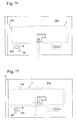
displaceable member 1 for receiving thecamer body 104, in the next step, thelatch 9 is pressed into thedisplaceable member 1, whereby, as explained above,pin 11 is moved out of swallow-tail groove 8, thus clearing thegroove 8 for engaging thecuboid block 16 ofcamera body 104. As shown inFig. 17 , when thelatch 9 is pressed in, its downward-projectingportion 39 would abut againstprojection 124 if thedisplaceable member 1 was pushed forward. I. e. when thedisplaceable member 1 is ready for receiving thecamera body 104, it cannot be pushed close to thevertical member 4, and an accidental collision of thecamera body 104 and thelens 102 is prevented. - When the
camera body 104 is properly locked to thedisplaceable member 1, as shown inFig. 18 , thelatch 9 comes out of thedisplaceable member 1 again, and the camera assembly is in the first position described above with respect toFig. 6 . Thelatch 9 does not interfere withprojection 124 any more now, but thedisplaceable member 1 is still locked to theimmobile member 103. In this first position, thecamera body 104 and thecamera support 100 can conveniently be handled as a unit; e.g. they may be removed from a tripod and placed in a storage box together for transport. In this first position, it is further possible to remove thelens 102 fromvertical branch 4 without having to fear interference between thelens 102 and thecamera body 104 which might damage one or the other. - By pressing inward the
latch 112,displaceable member 1 is unlocked fromimmobile member 103, so that thedisplaceable member 1 and thecamera body 104 supported by it can be pushed forward into the position ofFig. 19 , in which thecamera body 104 is close enough to thelens 102 for thebayonet coupling Fig. 6 . In the configuration ofFig. 19 , theprojection 124 is below thelatch 9, so that thelatch 9 cannot be pushed inwards. Thus, it is impossible to unlock thecamera body 104 from thedisplaceable member 1 while the camera body is so close to the lens that an uncontrolled movement of the camera body might cause damage to the lens. - In order to remove the camera body, the stages shown in
Figs. 17 to 19 are gone through in reverse order, i. e. thedisplaceable member 1 and thecamera body 104 are pulled away fromvertical member 4 untilblock 119 triggers pawl 113, thelatch 112 is pushed outward and lockingplate 109 is pulled upward, clampingshoe plate 116. Then latch 9 is pressed, whereby thecamera body 104, now in a safe distance fromlens 102, is pushed out of its locking position and can be removed. -
Fig. 20 is a perspective view, analogous toFig. 7 , of a camera support according to a second embodiment of the invention. Components of this embodiment which correspond to those of the embodiment ofFig. 7 have identical reference numerals. - The embodiment of
Fig. 20 differs from that ofFig. 7 in that thedisplaceable member 1 does not rest directly onimmobile member 103, but there is aplate 125 between the two.Plate 125 rests directly onimmobile member 103 and is connected todisplaceable member 1 by ashaft 126, allowing thedisplaceable member 1 to be tilted by a few degrees with respect to theimmobile member 103. Theplate 125 has a central opening, not shown in the Fig, through which stem 110 extends, allowing the assembly formed ofdisplaceable member 1 andplate 125 to be mounted onimmobile member 103 just as described above referring toFigs 13 to 19 . - A spring is concealed between
plate 125 anddisplaceable member 1 for urging the rear portion ofdisplaceable member 1 upward, compensating the weight of the camera body, so that the tilt of the camera body can be changed with little effort. - A
second screw 127 similar to screw 107 is provided for locking thedisplaceable member 1 with respect to theplate 125 at a desired tilt angle. When thebayonet coupling members screw 127 may be unlocked, allowing the camera body to yield to any torque that might occur between thebayonet coupling members screw 127 is locked again, the assembly is free from internal stress.
Claims (13)
- A camera support comprising a baseplate (1) on which first (5, 11) and second (19, 20) engaging means are formed for releasably engaging first (16) and second (21) portions of a camera body displaced along the baseplate (1) in an engaging direction, wherein the first engaging means (5, 11) defines an abutment position for the first portion of the camera body, and the second engaging means (19, 20) defines a space (38) between two sidewalls for slidably receiving a web (23) of the camera body, and wherein one of said sidewalls is displaceable towards the other and is coupled to a trigger (14) of the first engaging means so as to clamp the web (23) between the sidewalls when the trigger (14) is operated by the first portion (16) reaching the abutment position.
- The camera support of claim 1, comprising a first spring (37) for urging the sidewalls away from each other.
- The camera support of claim 1 or 2, wherein a flat outside surface of said baseplate (1) forms one of said sidewalls, and the other sidewall is formed by a locking plate (19) which is held above said flat surface by a stem (20) extending through a bore of said flat surface, which locking plate (19) extends from said stem (20) in opposite directions perpendicular to the sliding direction.
- The camera support of claim 3, wherein a wedge (34) is located between a pressing surface (36) of said stem (20) and an inside surface of said baseplate (1), the the wedge (34) being displaceable transversally with respect to the displacement direction of the camera body, and wherein the trigger (14) releasably engages a spring-loaded latch (9) which is displaceable transversally with respect to said displacement direction, and the wedge (34) is coupled to the latch (9) by a two-armed lever (31) extending in said displacement direction.
- The camera support of claim 4, wherein the stem (20) extends through a slot (35) of the wedge (34) and the pressing surface is formed on a plate (36) that extends sideways from said stem (20), and wherein the wedge (34) is urged by a second spring (33) towards a position in which the stem (20) is withdrawn into the baseplate (1).
- A camera assembly comprising a camera body (104)and a camera support (100) according to one of the claims 1 - 5, wherein the baseplate (1) is arranged as a displaceable member (1).
- The camera assembly of claim 6, wherein the camera support (100) comprises two orthogonal branches (101, 4), a first (4) of which is adapted to support a lens (102), and a second (101) of which has first locking means (5, 11, 19, 20) for releasably locking said camera body (104) to the second branch (101), said second branch (101) having an immobile member (103) with respect to the first branch (4), said first locking means (5, 11, 19, 20) being formed in said displaceable member (1) which is displaceable between a first position in which said camera body (104), when locked to the displaceable member (1) by said first locking means (5, 11, 19, 20), is spaced from the lens (102), and a second position in which the camera body (104) connects to the lens (102).
- The camera assembly of claim 7, wherein the displaceable member (1) is displaceable into the second position only if the locking means (5, 11, 19, 20) is in a locking configuration.
- The camera assembly of claim 8, wherein an operating member (9) of said locking means (5, 11, 19, 20) is displaceable perpendicular to the displacement direction of said displaceable member (1), and wherein the immobile member (103) has a projection (124) which blocks the operating member (9) in its locking configuration when the baseplate (1) is in the second position.
- The camera assembly of any of claims 7 to 9, wherein the locking means (5, 11, 19, 20) is locked in the locking configuration when the displaceable member (1) is in the second position, and wherein an operating member (9) of said locking means (5, 11, 19, 20) is displaceable perpendicular to the displacement direction of said displaceable member (1), and wherein the immobile member (103) has a projection (124) which blocks the displaceable member (1) in its first position when the locking means (5, 11, 19, 20) is in a non-locking configuration.
- The camera assembly of one of the preceding claims 6 - 10, wherein the displaceable member (1) and the camera body (104) have co-operating guide means (5, 19; 17, 22) for guiding the camera body (104) into a position in which the locking means are capable of locking the camera body (104) to the displaceable member (1) and wherein the guide means (5, 19; 17, 22) are adapted to guide the camera body (104) in the displacement direction of the displaceable member (1).
- The camera assembly of one of the preceding claims 6 - 11, wherein the displaceable member (1) is displaceable into a third position in which it is farther away from the first branch (4) than in the first and second positions, and in which it is unlocked from the immobile member (103).
- The camera assembly of one of the preceding claims 6 - 12, wherein second locking means (109-116) are provided for automatically and releasably locking the displaceable member (1) to the immobile member (103) when the displaceable member (103) is displaced from its first position to its second position, and wherein said second locking means comprises an undercut groove (117) formed in one of said members (103), a locking plate (119) which engages said undercut groove (117) and means (111) for pulling the locking plate(119) towards the other member (1).
Priority Applications (1)
| Application Number | Priority Date | Filing Date | Title |
|---|---|---|---|
| EP06777308A EP1891803B1 (en) | 2005-06-13 | 2006-06-12 | Camera support and respective camera assembly |
Applications Claiming Priority (4)
| Application Number | Priority Date | Filing Date | Title |
|---|---|---|---|
| EP05300476A EP1734742A1 (en) | 2005-06-13 | 2005-06-13 | Camera support |
| EP05300586A EP1744544A1 (en) | 2005-07-13 | 2005-07-13 | Camera assembly |
| PCT/EP2006/063099 WO2006134091A1 (en) | 2005-06-13 | 2006-06-12 | Camera support and respective camera assembly |
| EP06777308A EP1891803B1 (en) | 2005-06-13 | 2006-06-12 | Camera support and respective camera assembly |
Publications (2)
| Publication Number | Publication Date |
|---|---|
| EP1891803A1 EP1891803A1 (en) | 2008-02-27 |
| EP1891803B1 true EP1891803B1 (en) | 2008-11-12 |
Family
ID=36693620
Family Applications (1)
| Application Number | Title | Priority Date | Filing Date |
|---|---|---|---|
| EP06777308A Ceased EP1891803B1 (en) | 2005-06-13 | 2006-06-12 | Camera support and respective camera assembly |
Country Status (5)
| Country | Link |
|---|---|
| US (1) | US7946771B2 (en) |
| EP (1) | EP1891803B1 (en) |
| JP (1) | JP5415757B2 (en) |
| DE (1) | DE602006003658D1 (en) |
| WO (1) | WO2006134091A1 (en) |
Families Citing this family (15)
| Publication number | Priority date | Publication date | Assignee | Title |
|---|---|---|---|---|
| DE202007012388U1 (en) * | 2007-09-03 | 2007-12-06 | Arnold & Richter Cine Technik Gmbh & Co. Betriebs Kg | Device for connecting a camera to a carrying device |
| US8992238B2 (en) | 2010-07-12 | 2015-03-31 | Ferno-Washington, Inc. | Mounting system having a mounting plate with mounting studs and electrical contacts |
| US10307313B2 (en) | 2013-02-11 | 2019-06-04 | Ferno-Washington, Inc. | Equipment mounting system |
| AU2014214574B2 (en) | 2013-02-11 | 2016-10-20 | Ferno-Washington, Inc. | Equipment mounting system |
| US9944217B2 (en) | 2013-02-11 | 2018-04-17 | Ferno-Washington, Inc. | Equipment mounting system |
| US8806796B1 (en) | 2013-02-22 | 2014-08-19 | Prezine, Llc | Cam lever mount |
| US9769949B1 (en) * | 2013-08-20 | 2017-09-19 | Steven T. Kuntz | Mobile video, audio, and sensory apparatus |
| US10398207B2 (en) | 2014-02-11 | 2019-09-03 | Ferno-Washington, Inc. | Crash-ready, portable, compartmentalization device |
| US10398203B2 (en) | 2014-02-11 | 2019-09-03 | Ferno-Washington, Inc. | Crash-ready, portable, compartmentalization device |
| US11083265B2 (en) | 2014-02-11 | 2021-08-10 | Ferno-Washington, Inc. | Magnetic pouch attachment mechanism with crash stable locking teeth |
| CA3073768C (en) | 2014-07-18 | 2022-02-08 | Ferno-Washington, Inc. | A crash-ready, portable, compartmentalization device |
| CN106855168B (en) * | 2015-12-08 | 2018-08-21 | 泰州市创新电子有限公司 | The supporting rack of wedge shape plug Quick-disassembling mechanism at the top of modified column |
| US10209606B1 (en) * | 2016-11-17 | 2019-02-19 | Joseph Andrews | Selfie stand apparatus and method of use |
| US20230096795A1 (en) * | 2020-02-28 | 2023-03-30 | Technologies Cgc Inc. | Coupling systems for releasably coupling equipment to a patient transport systems |
| CN215111699U (en) * | 2021-01-29 | 2021-12-10 | 昆山蒲公英智能科技有限公司 | Quick connecting mechanism |
Family Cites Families (12)
| Publication number | Priority date | Publication date | Assignee | Title |
|---|---|---|---|---|
| JPS5923192A (en) * | 1982-07-29 | 1984-02-06 | 松下電器産業株式会社 | Fixture of apparatus |
| US4653709A (en) * | 1986-04-11 | 1987-03-31 | Paldino Arthur J | Tilt-pan head for cameras |
| FR2684461A1 (en) * | 1991-11-28 | 1993-06-04 | Aaton Sa | Filter box which can be used on professional ciné cameras or video cameras |
| US5444507A (en) * | 1994-03-22 | 1995-08-22 | Itt Corporation | Device for coupling night vision assembly to a video camcorder |
| DE29613027U1 (en) * | 1996-07-26 | 1996-09-26 | Chrosziel, Alfred, 81541 München | Quick lock plate for a camera |
| US6196504B1 (en) * | 1998-07-09 | 2001-03-06 | Maurice W. Lemke | Positive-lock-and-release device for camera mounting |
| JP2000278718A (en) * | 1999-03-26 | 2000-10-06 | Matsushita Electric Ind Co Ltd | Camera diagnostic/adjustment system, camera housing system, tripod mount used for these systems, and camera |
| DE50000716D1 (en) * | 1999-09-08 | 2002-12-12 | Boudard Pierre Olivier | camera plate |
| DE60302171T2 (en) * | 2002-04-03 | 2006-05-24 | Fujinon Corp. | Mount for a blur image compensator and a lens |
| US20040195466A1 (en) * | 2003-04-03 | 2004-10-07 | Chan-Min Ma | Device for organizing cables connected to video camera secured on a tripod |
| DE202004015006U1 (en) * | 2004-09-27 | 2004-12-23 | Müller, Jochen, Dr. | Mounting device for a tripod on a camera |
| US7720368B2 (en) * | 2005-07-15 | 2010-05-18 | Redrock Microsystems, Llc | System, method and apparatus for enhancing a projected image |
-
2006
- 2006-06-12 US US11/921,913 patent/US7946771B2/en not_active Expired - Fee Related
- 2006-06-12 WO PCT/EP2006/063099 patent/WO2006134091A1/en active Application Filing
- 2006-06-12 JP JP2008516296A patent/JP5415757B2/en not_active Expired - Fee Related
- 2006-06-12 EP EP06777308A patent/EP1891803B1/en not_active Ceased
- 2006-06-12 DE DE602006003658T patent/DE602006003658D1/en active Active
Also Published As
| Publication number | Publication date |
|---|---|
| WO2006134091A1 (en) | 2006-12-21 |
| EP1891803A1 (en) | 2008-02-27 |
| DE602006003658D1 (en) | 2008-12-24 |
| US7946771B2 (en) | 2011-05-24 |
| US20090220225A1 (en) | 2009-09-03 |
| JP5415757B2 (en) | 2014-02-12 |
| JP2008547042A (en) | 2008-12-25 |
Similar Documents
| Publication | Publication Date | Title |
|---|---|---|
| EP1891803B1 (en) | Camera support and respective camera assembly | |
| EP2200869B1 (en) | Extendable roof rack | |
| US6827319B2 (en) | Apparatus for quick fixation of a device to a tripod head | |
| US6196504B1 (en) | Positive-lock-and-release device for camera mounting | |
| US6431647B2 (en) | Swivel child car seat | |
| CA2947356C (en) | Manual clamp for key making machine | |
| JP3516243B2 (en) | Connector lever locking mechanism | |
| US7841784B2 (en) | Device for connecting a camera to a supporting device | |
| US11931911B2 (en) | Coupling mechanism | |
| JPH06126643A (en) | Vise jaw accessory system for mounting and releasing vise accessory while maintaining positional accuracy thereof | |
| US11105494B2 (en) | Locking device for a tactical light for Key-mod and M-lok rails | |
| US20220390816A1 (en) | Support head for video/photographic equipment | |
| EP1744544A1 (en) | Camera assembly | |
| US20130315662A1 (en) | Jig and a connector | |
| JP2001250638A (en) | Connector | |
| EP1734742A1 (en) | Camera support | |
| TWI652974B (en) | Pallet mechanism and its casing module | |
| JP3465181B2 (en) | Hook device | |
| JP2005042507A (en) | Outrigger and outrigger attached body | |
| JP2907258B2 (en) | Connector lock security member | |
| JP2609803B2 (en) | Belt locking device | |
| JP3306001B2 (en) | Connecting pins for scaffolding frames | |
| CN215722186U (en) | Support adjustment mechanism | |
| NL1033075C2 (en) | Coupling assembly with coupling head brake. | |
| US8393631B1 (en) | Automatic engaging and disengaging hitch assembly |
Legal Events
| Date | Code | Title | Description |
|---|---|---|---|
| PUAI | Public reference made under article 153(3) epc to a published international application that has entered the european phase |
Free format text: ORIGINAL CODE: 0009012 |
|
| 17P | Request for examination filed |
Effective date: 20071130 |
|
| AK | Designated contracting states |
Kind code of ref document: A1 Designated state(s): DE GB |
|
| DAX | Request for extension of the european patent (deleted) | ||
| RIN1 | Information on inventor provided before grant (corrected) |
Inventor name: DAM, JEFFREY Inventor name: MOERDIJK, VICTOR Inventor name: BONESCHANSCHER, MACHIEL |
|
| GRAP | Despatch of communication of intention to grant a patent |
Free format text: ORIGINAL CODE: EPIDOSNIGR1 |
|
| RBV | Designated contracting states (corrected) |
Designated state(s): DE GB |
|
| DAX | Request for extension of the european patent (deleted) | ||
| GRAS | Grant fee paid |
Free format text: ORIGINAL CODE: EPIDOSNIGR3 |
|
| GRAA | (expected) grant |
Free format text: ORIGINAL CODE: 0009210 |
|
| AK | Designated contracting states |
Kind code of ref document: B1 Designated state(s): DE GB |
|
| REG | Reference to a national code |
Ref country code: GB Ref legal event code: FG4D |
|
| REG | Reference to a national code |
Ref country code: GB Ref legal event code: 746 Effective date: 20081124 |
|
| REF | Corresponds to: |
Ref document number: 602006003658 Country of ref document: DE Date of ref document: 20081224 Kind code of ref document: P |
|
| PLBE | No opposition filed within time limit |
Free format text: ORIGINAL CODE: 0009261 |
|
| STAA | Information on the status of an ep patent application or granted ep patent |
Free format text: STATUS: NO OPPOSITION FILED WITHIN TIME LIMIT |
|
| 26N | No opposition filed |
Effective date: 20090813 |
|
| PGFP | Annual fee paid to national office [announced via postgrant information from national office to epo] |
Ref country code: GB Payment date: 20170627 Year of fee payment: 12 |
|
| PGFP | Annual fee paid to national office [announced via postgrant information from national office to epo] |
Ref country code: DE Payment date: 20170628 Year of fee payment: 12 |
|
| REG | Reference to a national code |
Ref country code: DE Ref legal event code: R119 Ref document number: 602006003658 Country of ref document: DE |
|
| GBPC | Gb: european patent ceased through non-payment of renewal fee |
Effective date: 20180612 |
|
| PG25 | Lapsed in a contracting state [announced via postgrant information from national office to epo] |
Ref country code: DE Free format text: LAPSE BECAUSE OF NON-PAYMENT OF DUE FEES Effective date: 20190101 Ref country code: GB Free format text: LAPSE BECAUSE OF NON-PAYMENT OF DUE FEES Effective date: 20180612 |