JP5413573B2 - Liquid ejecting head unit and liquid ejecting apparatus - Google Patents
Liquid ejecting head unit and liquid ejecting apparatus Download PDFInfo
- Publication number
- JP5413573B2 JP5413573B2 JP2009023148A JP2009023148A JP5413573B2 JP 5413573 B2 JP5413573 B2 JP 5413573B2 JP 2009023148 A JP2009023148 A JP 2009023148A JP 2009023148 A JP2009023148 A JP 2009023148A JP 5413573 B2 JP5413573 B2 JP 5413573B2
- Authority
- JP
- Japan
- Prior art keywords
- head
- liquid
- base plate
- liquid ejecting
- signal supply
- Prior art date
- Legal status (The legal status is an assumption and is not a legal conclusion. Google has not performed a legal analysis and makes no representation as to the accuracy of the status listed.)
- Active
Links
Images


Description
本発明は液体噴射ヘッドユニット及び液体噴射装置に関する。 The present invention relates to a liquid ejecting head unit and a liquid ejecting apparatus.
従来、インクジェット式プリンタ等のインクジェット式記録装置に代表される液体噴射装置は、カートリッジやタンク等に貯蔵されたインクなどの液体を液滴として噴射可能な液体噴射ヘッドが複数設けられた液体噴射ヘッドユニットを具備する。このような液体噴射ヘッドユニットとしては、例えば、複数の液体噴射ヘッドを共通の保持部材であるベースプレートに一方向に少しずつずらした状態でアライメントして固定しているものが知られている(例えば、特許文献1参照)。 2. Description of the Related Art Conventionally, a liquid ejecting apparatus represented by an ink jet recording apparatus such as an ink jet printer has a liquid ejecting head provided with a plurality of liquid ejecting heads capable of ejecting liquid such as ink stored in a cartridge or tank as droplets. A unit is provided. As such a liquid ejecting head unit, for example, a unit in which a plurality of liquid ejecting heads are aligned and fixed to a base plate that is a common holding member while being slightly shifted in one direction is known (for example, , See Patent Document 1).
上記の液体噴射ヘッドユニットでは、液体噴射ヘッドユニット単体でしか使用できないので、様々なサイズの記録対象に応じて様々なサイズの液体噴射ヘッドユニットを製造する必要がある。即ち、上記液体噴射ヘッドユニットは、汎用性に乏しいためコスト高であるという問題がある。 In the above liquid ejecting head unit, since the liquid ejecting head unit can be used only as a single unit, it is necessary to manufacture liquid ejecting head units of various sizes according to recording objects of various sizes. That is, the liquid ejecting head unit has a problem of high cost because it is poor in versatility.
さらに、上記のような従来の液体噴射ヘッドユニットでは、液体噴射ヘッドを構成する各部材が複雑に入り組んでいたために、ヘッド交換時の作業性が低いという問題もある。 Further, the conventional liquid jet head unit as described above has a problem that workability at the time of head replacement is low because each member constituting the liquid jet head is complicated.
そこで、本発明の課題は、上記従来技術の問題点を解決することにあり、汎用性が高く、かつ、ヘッド交換時の作業性も高い液体噴射ヘッドユニット及びこれを用いた液体噴射装置を提供しようとするものである。 Accordingly, an object of the present invention is to solve the above-described problems of the prior art, and provide a liquid ejecting head unit having high versatility and high workability when replacing the head, and a liquid ejecting apparatus using the same. It is something to try.
本発明の液体噴射ヘッドユニットは、開口部が設けられたベースプレートを備えると共に、該ベースプレート上に、液体を噴射するノズル開口が複数形成された液体噴射面が前記開口部から露出する液体噴射ヘッドと、前記液体噴射ヘッドに液体を供給する液体供給管と、前記液体噴射ヘッドに駆動信号を供給する信号供給ユニットと、ベースプレートに固定され前記液体噴射ヘッド上に前記信号供給ユニットを支持するフレームとを備え、これらのベースプレート上に備えられた各部材が、前記ベースプレートを底面とした柱状の空間内に収まるように構成され配置されていると共に、信号供給ユニットがベースプレートに対して垂直方向に離間できるように構成され、前記信号供給ユニットが、対となった回路基板と、前記回路基板間に配置されかつ各回路基板に固定されると共に前記フレームに固定された放熱器と、各放熱器に設けられた複数のフィンと、該フィンの上部に配置される筒状部材を備えた固定プレートとを備えていることを特徴とする。
本発明の液体噴射ヘッドユニットにおいては、ベースプレート上に備えられた各部材が、前記ベースプレートを底面とした柱状の空間内に収まるように構成され配置されていることで、複数の液体噴射ヘッドユニットを接続する場合であっても部材が接触しないので、汎用性が高い。また、信号供給ユニットが、ベースプレート上の最上部に配置され、かつベースプレートに対して垂直方向に離間できるように構成されていることで、ヘッドユニットを複数接続した場合であっても信号供給ユニットを簡易にヘッドユニットから取り外すことが可能である。これにより、ヘッド交換時の作業性が向上する。さらにまた、このように各部材を配置することで、ヘッドの放熱性が上昇する。
The liquid jet head unit of the present invention is provided with a base plate opening mouth portion is provided, on the base plate, a liquid ejecting surface of the nozzle opening is formed with a plurality of ejecting the liquid you exposed from the front KiHiraki opening the liquid body jet head, a liquid supply pipe for supplying a liquid prior Symbol liquid ejecting head, wherein the signal supply unit that to supply drive signals to the liquid jet head, is fixed to the base plate the on the liquid jet heads A frame for supporting the signal supply unit, and each member provided on the base plate is configured and arranged so as to be accommodated in a columnar space with the base plate as a bottom surface. It is configured to be spaced in a direction perpendicular to the signal supply unit, a circuit board paired, between the circuit board A radiator disposed on and fixed to each circuit board and fixed to the frame; a plurality of fins provided on each radiator; and a fixing plate including a cylindrical member disposed on the fins; characterized in that it comprises a.
In the liquid ejecting head unit of the present invention, each member provided on the base plate is configured and arranged so as to be accommodated in a columnar space with the base plate as a bottom surface. Even in the case of connection, since the members do not come in contact, the versatility is high. Further, the signal supply unit is arranged at the uppermost part on the base plate and can be separated in the vertical direction with respect to the base plate, so that the signal supply unit can be connected even when a plurality of head units are connected. It can be easily removed from the head unit. Thereby, workability at the time of head replacement is improved. Furthermore, by disposing each member in this way, the heat dissipation of the head is increased.
ここで、前記フレームの高さは可変であるように構成されていることが好ましい。このように構成することで、フレームの高さを変えて信号供給ユニットをベースプレートに対して垂直方向に離間し、その状態でヘッド交換作業を行うことができるので、作業性が向上する。 Here, it is preferable that the height of the frame is configured to be variable. With this configuration, the height of the frame is changed to separate the signal supply unit in the vertical direction with respect to the base plate, and the head replacement work can be performed in this state, so that workability is improved.
また、前記フレームは、前記ベースプレートに固定された脚部と該脚部から着脱可能な台部とからなり、前記放熱器は、前記台部に固定されたことが好ましい。このように構成することで、信号供給ユニットが台部と一体化するので、より信号供給ユニットをヘッドユニットから離間させやすく、作業性が向上する。
Further, the frame consists of a possible base portion detachable from said base plate which is fixed to the leg and the leg portion, said heat sink, and is preferably kite is secured to the base portion. With this configuration, since the signal supply unit is integrated with the base, it is easier to separate the signal supply unit from the head unit and workability is improved.
さらに、前記回路基板と前記液体噴射ヘッドとを繋ぐ配線部材をさらに備え、前記液体噴射ヘッドの液体噴射面と逆の面に、前記液体供給管に接続される液体導入口と前記配線部材が接続されるコネクターとを備えたことが好ましい。このように構成することで、ヘッド交換時に液体供給管及び配線部材を上部から取り外しやすいので、作業性が向上する。 Furthermore, a wiring member that connects the circuit board and the liquid ejecting head is further provided, and a liquid introduction port connected to the liquid supply pipe and the wiring member are connected to a surface opposite to the liquid ejecting surface of the liquid ejecting head. It is preferable that the connector is provided. With this configuration, the liquid supply pipe and the wiring member can be easily removed from the upper part when replacing the head, so that workability is improved.
本発明の液体噴射装置は、上記したいずれかの液体噴射ヘッドユニットを備えたことを特徴とする。上記した液体噴射ヘッドユニットを備えることで、汎用性が高く、また、作業性がよい。 The liquid ejecting apparatus according to the invention includes any one of the liquid ejecting head units described above. By providing the liquid jet head unit described above, versatility is high and workability is good.
はじめに、本発明の液体噴射ヘッドユニットであるインクジェット式記録ヘッドユニット1(以下、単にヘッドユニットという)に用いられるインクジェット式記録ヘッド2(以下、単にヘッドという)について、図1を用いて説明する。図1は、ヘッドの構成を説明するための図であり、(a)は、ヘッドの斜視図、(b)はヘッドの要部下面図である。 First, an ink jet recording head 2 (hereinafter simply referred to as a head) used in an ink jet recording head unit 1 (hereinafter simply referred to as a head unit) which is a liquid jet head unit of the present invention will be described with reference to FIG. 1A and 1B are diagrams for explaining the configuration of the head, where FIG. 1A is a perspective view of the head, and FIG. 1B is a bottom view of the main part of the head.
ヘッド2は、入力された駆動信号に応じてインクをノズル開口から噴射するヘッド本体21を備える。ヘッド本体21の一端面(上端面)には、インクをヘッド本体21内に導入するためのインク導入口22、及び駆動信号を入力するための後述するFFCが挿入されるコネクター23が設けられている。なお、本実施形態ではインク導入口22は二つ設けたが、一つでもよい。また、ヘッド本体21の他端面(下端面、液体噴射面)24には、インクを噴射するノズル開口25が形成されている。ノズル開口25は、ヘッド本体21の長手方向に列状に並設されており、ノズル列26を形成している。インク導入口22とノズル開口25とは、ヘッド本体21内部に形成された図示しないインク流路を介して接続されている。このインク流路には図示しない圧力発生手段が設けられており、各ヘッド2は、コネクター23を介してヘッド2に入力された駆動信号に応じて、圧力発生手段によりインクをノズル開口25から噴射する。また、ヘッド本体21の外周には、ヘッド本体21を後述するベースプレートに固定するための固定部材27が設けられている。
The
このようなヘッド2を複数備えた本実施形態のヘッドユニット1について、図2を用いて説明する。図2は、ヘッドユニットの斜視図である。ヘッドユニット1は、複数の(図中では例として8個の)ヘッド2を備えている。各ヘッド2は、固定部材27を介してそれぞれベースプレート3に取り外し可能となるように固定されている。なお、以下、固定された状態におけるこのヘッド本体21の短手方向に沿った方向を第一方向とし、このヘッド本体21の長手方向に沿った方向を第二方向とする。
A
本実施形態においては、ベースプレートを底面とした柱状の空間内に収まるように、全てのヘッドユニット1の構成部材、即ち、ベースプレート3に固定されたヘッド2(2a〜2d)、ヘッド2にインクを供給するインク供給管4(液体供給管)、ベースプレート3に立設けられたフレーム5、フレーム5上に載置された信号供給ユニット6が構成され配置されている。言い換えると、ヘッドユニット1は、ベースプレート3を下方から見上げた場合に、全ての構成部材、即ち複数のヘッド2、インク供給管4、フレーム5及び信号供給ユニット6が見えないように構成されている。このようにヘッドユニット1の構成部材がベースプレート3を底面とした柱状の空間内に収められていることで、本実施形態のヘッドユニット1は、ヘッドユニット1同士を構成部材が接触せずに組み合わせることができ、汎用性が高いものとなっている。
In the present embodiment, ink is applied to all the constituent members of the
各ヘッド2は、各ヘッド2を第一方向に沿って二つ並べたものを一組とし、この一組を略千鳥状となるように(第2方向において互いにずれた状態となるように)、かつ、各ヘッド2のノズル列26(図1参照)がその端部で第一方向に並設された別の一組のヘッド2のノズル列26の端部と重なるようにベースプレート3に配置されている。このように略千鳥状となるように、かつノズル列の端部をオーバーラップさせてヘッド2を配置していることで、第二方向ではノズル列26がとぎれることがないため、より広範囲の印刷を高速で行わせることができる。また、ヘッド本体21の短手方向に二つ並べたものを一組として配置することで、一組のヘッド2のノズル列のピッチを半ピッチずらした状態とすることにより解像度を高くすることができる。
Each
ベースプレート3は、ヘッド本体21に応じて形成されており、略千鳥状となるように配置されたヘッド2に合わせて、第二方向に沿ってずれた形状となっている。また、ベースプレート3には、各ヘッド2のノズル開口25が形成された下端面24が露出するように、複数の開口部31が設けられている。
The
また、各ヘッド本体21の長手方向の長さは、各ヘッド本体21のノズル開口が並設されてなるノズル開口列の長さの2倍以下となるように構成されている。これにより、ベースプレート3におけるヘッド2の設置面積を小さくすることができる。
The length of each
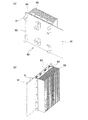
各ヘッド2のインク導入口22(図1参照)には、図示しないインク貯留部に接続されたインク供給管4が接続され、各ヘッド2にインクが供給される。このインク供給管4についてさらに図3及び図4を用いて説明する。図3は、フレーム及び信号供給ユニットを除去した状態のヘッドユニットの上面図である。図4は、ヘッド及びヘッド側流路を説明するための図であり、(a)斜視図、(b)側面図、(c)上面図である。本実施形態では、インク供給管4は、2本設けられている。
The ink supply port 4 (see FIG. 1) of each
各インク供給管4は、図3に示すようにベースプレート3を底面とした柱状の空間内に収まるように構成され配置されている。各インク供給管4は、幹流路管(共通液体流路管)41、枝流路管42(42a〜42d)を備える。幹流路管41は、端部で図示しないインク貯留部に接続されている。幹流路管41から分岐した枝流路管42a〜42dは、各端部で継手44及びヘッド側枝流路管43(43a〜43d)を介してヘッド2に接続されている。ヘッド側枝流路管43a〜43dは、それぞれ図4に示すように2つに分岐して一つのヘッド2の各インク導入口22に接続されている。継手44は、枝流路管42a〜42dとヘッド側枝流路管43a〜43dとを接続してインクを流通させることができるように構成されていると共に、ヘッド交換時にこの継手44を外しても継手44を外した部分からインクが漏れないように構成されている。
As shown in FIG. 3, each
このようにインク供給管4が構成された本実施形態においては、交換が必要なヘッド2の継手44のみを外して、ヘッド2及びこのヘッド2に接続されたヘッド側枝流路管43を取り外してヘッド2を交換できる。この場合に、例えばインク供給管4自体を取り替える必要はなく、交換が不要なヘッド2に接続するインク供給管4については触れずに交換作業を行うことができるので、ヘッド交換時の作業性を向上させることができる。
In this embodiment in which the
具体的には、幹流路管41は、第一分岐部45で二つの枝流路管42a、42bに分岐する。枝流路管42aは、分岐後下方へ延設された枝流路であり、この枝流路管42aはヘッド2aに接続されたヘッド側枝流路管43aに接続する。ヘッド側枝流路管43aは、ヘッド2aに設けられた二つのインク導入口22に接続する。枝流路管42bは、分岐後水平方向へ延設されており、ヘッド2aの第二方向に沿って配置されたヘッド2bのヘッド側枝流路管43bに接続される。また、枝流路管42bからは分岐点46においてさらに枝流路管42cが分岐しており、この枝流路管42cは、分岐後第一方向に沿うように延設されており、ヘッド2aの第一方向に並設されたヘッド2cのヘッド側枝流路管43cに接続される。また、枝流路管42cからは分岐点47においてさらに枝流路管42dが分岐しており、枝流路管42dは、ヘッド2cの第二方向に並設されたヘッド2dのヘッド側枝流路管43dに接続される。他方のインク供給管4も、同様に構成されて、4つのヘッド2にインクを供給するように構成されている。
Specifically, the
ベースプレート3上にはフレーム5が設けられ、このフレーム5には、各ヘッドを駆動するための信号を供給する信号供給ユニット6が載置されている。フレーム5は、4つの脚部51と、脚部51によって支持された台部52とからなる。この脚部51がヘッド2に隣接した位置、即ちベースプレート3の第二方向に沿ってそれぞれ配置されていることで、ベースプレート3の第二方向の長さを短くすることが可能である。また、脚部51の高さは、台部52とベースプレート3との間にヘッド2、ヘッド側枝流路管43及び枝流路管42が収納されるように構成されている。
A
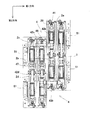
台部52は脚部51から着脱自在に設けられており、この台部52には信号供給ユニット6が載置されている。このように台部52上に信号供給ユニット6が載置されていることで、台部52を取り外すことにより信号供給ユニット6をヘッドユニット1から取り外すことができるので、ヘッド交換を行いやすい。この信号供給ユニット6について、図5〜図8も用いて詳細に説明する。図5は、ヘッドユニットの上面図であり、図6は筒状部材を除去した場合のヘッドユニットの上面図であり、図7は、信号供給ユニットの一部分解斜視図であり、図8は、信号供給ユニットの要部斜視図である。
The
図5に示すように、このフレーム5及び信号供給ユニット6も、ベースプレート3を底面とした柱状の空間内に全て収納されている。信号供給ユニット6は、一対の回路基板61を備えている。各回路基板61は、第二方向に並設された二組のヘッド2のヘッド本体21に駆動信号を供給するものである。この回路基板61のコンデンサーC等(図7、8、10、11、12以外では省略した)が設置された回路形成部62が形成された回路形成面63が互いに外側を向くように、かつ、回路形成部62が重なるように回路基板61は並設されている。この回路形成部62間には、回路基板61で発生する熱を放熱させるためのヒートシンク(放熱器)64が固定されている。ヒートシンク64は、さらに台部52にも固定されている。このヒートシンク64は、ヒートシンク64で放熱効率を向上させるようにフィン65がベースプレート3に対して垂直方向に設けられている。この放出した熱をさらに排出しやすいように、フレーム5のフィン65に対向する部分には、図7に示すように開口54が形成されている。また、ヒートシンク64の上部には、2つの筒状部材66が固定プレート67を介してヒートシンク64に固定されている。即ち、一対のヒートシンク64は、固定プレート67により対向した状態で保持されている。なお、この固定プレート67には、筒状部材66の開口に応じて開口が形成されている。本実施形態の信号供給ユニット6では、このようにベースプレート3に対して垂直方向にフィン65を備え、かつ、フィン65に対向するように開口54及び筒状部材66を備えていることから、ベースプレート3に対して垂直方向に熱を逃がしやすい構成となっている。また、本実施形態では、ヒートシンク64が回路基板61に固定されると共に、ヒートシンク64には、固定プレート67及び台部52が固定されるように構成されている。従って、信号供給ユニット6が台部52と一体となっているため、台部52を取り外すことにより、信号供給ユニット6を取り外すことができ、ヘッド交換時の作業性を向上させることができる。
As shown in FIG. 5, the
図2に戻り、回路基板61には、各ヘッド2に駆動信号を供給するための配線部材(FFC)68が設けられている。FFC68は、回路基板61の回路形成部62にその一端で接続されて、かつ、他端はヘッド本体21のコネクター23に接続されて、各駆動信号はFFC68を介して各ヘッド本体21に供給されている。なお、コネクター23とFFC68とをコネクター付の中継基板を介して接続するように構成してもよい。フレーム5の脚部51には開口53が設けられ、この開口53にFFC68が挿入される。この脚部51は、前述のようにヘッド2に隣接した位置に設けられているので、この開口53にFFC68を挿通させることで、FFC68を捻らずにヘッド2に接続することが可能である。
Returning to FIG. 2, the
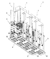
このようにベースプレート3を底面とした柱状の空間内に全ての構成部材が収まるように構成されていることで、本実施形態のヘッドユニット1は、2以上のヘッドユニット1を構成部材同士が接触することなく接続することができるので、汎用性が高い。例えば、図9に示すようにヘッド本体21の長手方向に複数のヘッドユニット1を並べて一のヘッドユニットIを構成することができる。この場合にも、ヘッド2が千鳥状に配置されていることによりベースプレート3が第二方向にずれた形状となっていることで、一のヘッドユニットのベースプレート3の凸部32を別のヘッドユニットのベースプレート3の凹部33に嵌合することができる。この場合にも、各ヘッド2のノズル列26(図1参照)は端部でオーバーラップしているので、ヘッドユニット1を複数接続した一のヘッドユニットIでも、ノズル列26が第二方向に対してとぎれることがない。従って、より広範囲の印刷を高速で行わせることができる。また、各ヘッド2、各インク供給管4、フレーム5及び信号供給ユニット6は、ベースプレート3の中心を対称軸とした場合に、回転対称となるように配置されている。このように構成されていることで、ヘッドユニット1を接続する場合に接続方向を考慮する必要がなく、汎用性が高い。
As described above, the
本実施形態のヘッドユニット1は、上記した構成により汎用性が高い上に、上記構成により、ヘッド2が故障した場合に各ヘッド2を交換しやすいという利点がある。この点について、図10、11を用いて以下説明する。図10は、ヘッドユニットから信号供給ユニットを取り外した状態を示す斜視図である。図11はヘッドユニットの側面図である。
The
本実施形態のヘッドユニット1では、上述したように、信号供給ユニット6がフレーム5の台部52上に載置されている。台部52は脚部51から着脱可能であるように構成されているので、ヘッド2の交換時には、はじめに、ヘッド2の交換時に作業性を低下させる信号供給ユニット6を台部52ごとベースプレート3に対して垂直方向に離間することが可能である。これにより、ヘッド交換作業の作業性が向上する。このように信号供給ユニット6をベースプレート3に対して垂直方向に離間する場合に、FFC68を交換しないヘッドから取り外さなくてもよいように、例えば、図11に示すようにFFC68は予め長く設けられていてもよい。図11では、FFC68は、図2に示す場合よりも長く設けられているので、ヘッド2の交換作業時に信号供給ユニット6を台部52ごとベースプレート3に対して垂直方向に離間する場合に、交換が不要なヘッド2からFFC68を外す必要がない。また、その状態で例えば信号供給ユニット6及び台部52を隣接する別のヘッドユニット1上に載置して、より作業効率を上昇させることも可能である。
In the
そして、信号供給ユニット6を離間させた状態で、ヘッド2に接続されているFFC68及び継手44(図2参照)を外し、次いで、ヘッド2をベースプレート3から外すことにより、ヘッド側枝流路管43が接続された状態のヘッド2をベースプレート3から簡易に取り外すことが可能である。この場合、ヘッド本体21の上端面にインク導入口22及びコネクター23(図1参照)が設けられていることで、ヘッド交換時にFFC68及び継手44を取り外しやすい。このように、本実施形態のヘッドユニット1は、ベースプレート3に対して垂直方向のみの部品着脱操作により個々のヘッド2を取り外すことができる。従って、ヘッド交換の作業性に優れている。
Then, with the
別の実施形態のヘッドユニット1について、図12を用いて説明する。この別の実施形態は、上述した実施形態とはフレーム5の構成が異なる。即ち、本実施形態においては、フレーム5の脚部51は、ベースプレート3に固定された第一脚部54と、第一脚部54にスライド可能に構成され、台部52に固定された第二脚部55とからなる。また、第一脚部54には、ストッパー56が設けられて、第二脚部55の下端部に嵌合して第二脚部55を保持することができるように構成されている。このようにフレーム5の脚部51がそれぞれ二つの部材から構成され、高さを可変することができるので、ヘッド交換時に第二脚部55を上方にスライドさせることにより、信号供給ユニット6をベースプレート3に対して垂直方向に移動させることができる。このように信号供給ユニット6を離間し、その位置で保持することができるので、ヘッド交換時の作業性をより向上させることができる。
A
また、上記各実施形態のヘッドユニット1は、第一方向がインクジェット式記録装置に代表される液体噴射装置の記録用紙や基板等の被記録媒体を搬送する方向と一致するように装置本体に固定されることで、被記録媒体を第一方向に搬送するだけで記録可能ないわゆるライン式記録装置に適用することができる。
Further, the
なお、液体噴射装置は、特にこれに限定されず、例えば、ヘッドユニット1を被記録媒体の搬送方向とは直交する方向に移動可能に設けられたキャリッジ等の移動手段に搭載することで、ヘッドユニット1によって形成された第二方向に連続するノズル列の長さよりも幅広の被記録媒体に印刷することができる。すなわち、ヘッドユニット1を、第一方向が被記録媒体の搬送方向と一致するように配置し、ヘッドユニット1を第二方向に移動させると共に、被記録媒体を第一方向に移動させながら記録を行うことができる。
The liquid ejecting apparatus is not particularly limited to this. For example, the
上述した実施形態では、一つのベースプレート3に8つのヘッド2を固定してヘッドユニット1を構成するようにしたが、特にこれに限定されず、2つ以上のヘッド2で構成してもよい。
In the embodiment described above, the
1 インクジェット式記録ヘッドユニット(ヘッドユニット)、 2 インクジェット式記録ヘッド(ヘッド)、 3 ベースプレート、 4 インク供給管、 5 フレーム、 6 信号供給ユニット、 21 ヘッド本体、 22 インク導入口、 23 コネクター、 24 下端面、 25 ノズル開口、 26 ノズル列、 27 固定部材、 31 開口部、 41 幹流路管、 42a〜42d 枝流路管、 43a〜43d ヘッド側枝流路管、 44 継手、 45 第一分岐部、 51 脚部、 52 台部、 53 開口、 54 第一脚部、 55 第二脚部、 61 回路基板、 62 回路形成部、 63 回路形成面、 64 ヒートシンク、 65 フィン、 66 筒状部材、 67 固定プレート、 68 FFC、 I ヘッドユニット、 C コンデンサー
DESCRIPTION OF
Claims (5)
該ベースプレート上に、
液体を噴射するノズル開口が複数形成された液体噴射面が前記開口部から露出する液体噴射ヘッドと、
前記液体噴射ヘッドに液体を供給する液体供給管と、
前記液体噴射ヘッドに駆動信号を供給する信号供給ユニットと、
ベースプレートに固定され前記液体噴射ヘッド上に前記信号供給ユニットを支持するフレームとを備え、
これらのベースプレート上に備えられた各部材が、前記ベースプレートを底面とした柱状の空間内に収まるように構成され配置されていると共に、信号供給ユニットがベースプレートに対して垂直方向に離間できるように構成され、
前記信号供給ユニットが、対となった回路基板と、前記回路基板間に配置されかつ各回路基板に固定されると共に前記フレームに固定された放熱器と、各放熱器に設けられた複数のフィンと、該フィンの上部に配置される筒状部材を備えた固定プレートとを備えていることを特徴とする液体噴射ヘッドユニット。 Provided with a base plate opening mouth portion is provided,
On the base plate,
The liquid body jet head the liquid ejection surface of the nozzle opening is formed with a plurality of ejecting the liquid you exposed from the front KiHiraki opening,
A liquid supply pipe for supplying a liquid prior Symbol liquid jet head,
And signal supply unit that to supply drive signals to said liquid ejecting head,
Is fixed to the base plate and a frame for supporting the signal supply unit on the liquid ejecting heads,
Each member provided on the base plate is configured and arranged so as to be accommodated in a columnar space with the base plate as a bottom surface, and the signal supply unit is configured to be vertically separated from the base plate. It is,
The signal supply unit includes a pair of circuit boards, a radiator disposed between the circuit boards and fixed to each circuit board and fixed to the frame, and a plurality of fins provided in each radiator And a fixing plate including a cylindrical member disposed on the upper portion of the fin .
前記放熱器は、前記台部に固定されたことを特徴とする請求項1又は2に記載の液体噴射ヘッドユニット。 The frame includes a leg portion fixed to the base plate and a base portion detachable from the leg portion,
The radiator liquid jet head unit according to claim 1 or 2, characterized in the kite is secured to the base portion.
前記液体噴射ヘッドの前記液体噴射面と逆の面に、前記液体供給管に接続される液体導入口と前記配線部材が接続されるコネクターとを備えたことを特徴とする請求項1〜3のいずれか一項に記載の液体噴射ヘッドユニット。 A wiring member connecting the circuit board and the liquid jet head;
The liquid injection port connected to the liquid supply pipe and a connector connected to the wiring member are provided on a surface opposite to the liquid ejection surface of the liquid ejection head. The liquid jet head unit according to any one of the above.
Priority Applications (1)
| Application Number | Priority Date | Filing Date | Title |
|---|---|---|---|
| JP2009023148A JP5413573B2 (en) | 2009-02-03 | 2009-02-03 | Liquid ejecting head unit and liquid ejecting apparatus |
Applications Claiming Priority (1)
| Application Number | Priority Date | Filing Date | Title |
|---|---|---|---|
| JP2009023148A JP5413573B2 (en) | 2009-02-03 | 2009-02-03 | Liquid ejecting head unit and liquid ejecting apparatus |
Publications (3)
| Publication Number | Publication Date |
|---|---|
| JP2010179499A JP2010179499A (en) | 2010-08-19 |
| JP2010179499A5 JP2010179499A5 (en) | 2012-02-09 |
| JP5413573B2 true JP5413573B2 (en) | 2014-02-12 |
Family
ID=42761418
Family Applications (1)
| Application Number | Title | Priority Date | Filing Date |
|---|---|---|---|
| JP2009023148A Active JP5413573B2 (en) | 2009-02-03 | 2009-02-03 | Liquid ejecting head unit and liquid ejecting apparatus |
Country Status (1)
| Country | Link |
|---|---|
| JP (1) | JP5413573B2 (en) |
Families Citing this family (8)
| Publication number | Priority date | Publication date | Assignee | Title |
|---|---|---|---|---|
| JP2013158992A (en) * | 2012-02-03 | 2013-08-19 | Seiren Co Ltd | Ink-jet recording device |
| JP5966758B2 (en) * | 2012-03-12 | 2016-08-10 | 株式会社リコー | Inkjet recording device |
| JP6268846B2 (en) * | 2013-09-19 | 2018-01-31 | セイコーエプソン株式会社 | Head unit and image recording apparatus |
| JP2017081049A (en) * | 2015-10-30 | 2017-05-18 | セイコーエプソン株式会社 | Liquid discharge device |
| JP6784028B2 (en) | 2016-02-02 | 2020-11-11 | セイコーエプソン株式会社 | Liquid injection unit, liquid injection head, support for liquid injection head |
| JP6825346B2 (en) * | 2016-12-15 | 2021-02-03 | セイコーエプソン株式会社 | Manufacturing method of liquid injection head and liquid injection head unit |
| CN109421374B (en) * | 2017-08-30 | 2021-02-09 | 上海锐尔发数码科技有限公司 | Piezoelectric ink-jet printing chip and packaging structure for packaging piezoelectric ink-jet printing chip |
| JP6922631B2 (en) * | 2017-09-29 | 2021-08-18 | ブラザー工業株式会社 | Head unit and liquid discharge device |
Family Cites Families (3)
| Publication number | Priority date | Publication date | Assignee | Title |
|---|---|---|---|---|
| JP2004042417A (en) * | 2002-07-11 | 2004-02-12 | Canon Inc | Ink jet recorder |
| JP4608898B2 (en) * | 2004-02-05 | 2011-01-12 | ブラザー工業株式会社 | Recording device |
| JP2007090695A (en) * | 2005-09-29 | 2007-04-12 | Konica Minolta Holdings Inc | Line head and ink-jet printing device |
-
2009
- 2009-02-03 JP JP2009023148A patent/JP5413573B2/en active Active
Also Published As
| Publication number | Publication date |
|---|---|
| JP2010179499A (en) | 2010-08-19 |
Similar Documents
| Publication | Publication Date | Title |
|---|---|---|
| JP5413573B2 (en) | Liquid ejecting head unit and liquid ejecting apparatus | |
| JP5679665B2 (en) | Inkjet recording head | |
| JP5549797B2 (en) | Liquid ejecting head unit and liquid ejecting apparatus | |
| US10457060B2 (en) | Drop-on-demand inkjet print bar | |
| JP5397595B2 (en) | Liquid ejecting head unit and liquid ejecting apparatus | |
| US9802414B2 (en) | Array-type ink cartridge | |
| JP2017196858A (en) | Liquid emitting head and liquid emitting device | |
| JP2021138149A (en) | Liquid discharge head | |
| JP5696862B2 (en) | Liquid ejecting head unit and liquid ejecting apparatus | |
| JP2005319817A (en) | Recording device | |
| JP4407273B2 (en) | Inkjet recording device | |
| JP4608898B2 (en) | Recording device | |
| JP2008087302A (en) | Liquid jet device | |
| JP6413805B2 (en) | Liquid ejection device | |
| JP2017209948A (en) | Liquid jetting device | |
| JP4960721B2 (en) | Print head and method of adjusting position of unit head of print head | |
| JP2008279734A (en) | Liquid droplet ejector | |
| JP2005193579A (en) | Inkjet recording apparatus | |
| JP2018043452A (en) | Inkjet head, inkjet recording device and inkjet head manufacturing method | |
| JP2018016028A (en) | Liquid discharge head, liquid discharge device and manufacturing method | |
| JP7301620B2 (en) | liquid ejection head | |
| JP2010179500A (en) | Liquid-jet head unit and liquid-jet apparatus | |
| JP2018012303A (en) | Liquid discharge head | |
| JP2007136701A (en) | Liquid ejector | |
| JP4590867B2 (en) | Inkjet recording device |
Legal Events
| Date | Code | Title | Description |
|---|---|---|---|
| A521 | Written amendment |
Free format text: JAPANESE INTERMEDIATE CODE: A523 Effective date: 20111212 |
|
| A621 | Written request for application examination |
Free format text: JAPANESE INTERMEDIATE CODE: A621 Effective date: 20111212 |
|
| A977 | Report on retrieval |
Free format text: JAPANESE INTERMEDIATE CODE: A971007 Effective date: 20121122 |
|
| A131 | Notification of reasons for refusal |
Free format text: JAPANESE INTERMEDIATE CODE: A131 Effective date: 20121205 |
|
| A521 | Written amendment |
Free format text: JAPANESE INTERMEDIATE CODE: A523 Effective date: 20130124 |
|
| TRDD | Decision of grant or rejection written | ||
| A01 | Written decision to grant a patent or to grant a registration (utility model) |
Free format text: JAPANESE INTERMEDIATE CODE: A01 Effective date: 20131016 |
|
| A61 | First payment of annual fees (during grant procedure) |
Free format text: JAPANESE INTERMEDIATE CODE: A61 Effective date: 20131029 |
|
| R150 | Certificate of patent or registration of utility model |
Ref document number: 5413573 Country of ref document: JP Free format text: JAPANESE INTERMEDIATE CODE: R150 |
|
| S531 | Written request for registration of change of domicile |
Free format text: JAPANESE INTERMEDIATE CODE: R313531 |
|
| R350 | Written notification of registration of transfer |
Free format text: JAPANESE INTERMEDIATE CODE: R350 |