JP5413402B2 - Fuel tank structure - Google Patents
Fuel tank structure Download PDFInfo
- Publication number
- JP5413402B2 JP5413402B2 JP2011115921A JP2011115921A JP5413402B2 JP 5413402 B2 JP5413402 B2 JP 5413402B2 JP 2011115921 A JP2011115921 A JP 2011115921A JP 2011115921 A JP2011115921 A JP 2011115921A JP 5413402 B2 JP5413402 B2 JP 5413402B2
- Authority
- JP
- Japan
- Prior art keywords
- fuel tank
- tank
- fuel
- valve
- valve body
- Prior art date
- Legal status (The legal status is an assumption and is not a legal conclusion. Google has not performed a legal analysis and makes no representation as to the accuracy of the status listed.)
- Expired - Fee Related
Links
Images

Classifications
-
- B—PERFORMING OPERATIONS; TRANSPORTING
- B60—VEHICLES IN GENERAL
- B60K—ARRANGEMENT OR MOUNTING OF PROPULSION UNITS OR OF TRANSMISSIONS IN VEHICLES; ARRANGEMENT OR MOUNTING OF PLURAL DIVERSE PRIME-MOVERS IN VEHICLES; AUXILIARY DRIVES FOR VEHICLES; INSTRUMENTATION OR DASHBOARDS FOR VEHICLES; ARRANGEMENTS IN CONNECTION WITH COOLING, AIR INTAKE, GAS EXHAUST OR FUEL SUPPLY OF PROPULSION UNITS IN VEHICLES
- B60K15/00—Arrangement in connection with fuel supply of combustion engines or other fuel consuming energy converters, e.g. fuel cells; Mounting or construction of fuel tanks
- B60K15/03—Fuel tanks
- B60K2015/03256—Fuel tanks characterised by special valves, the mounting thereof
- B60K2015/03263—Ball valves
-
- B—PERFORMING OPERATIONS; TRANSPORTING
- B60—VEHICLES IN GENERAL
- B60K—ARRANGEMENT OR MOUNTING OF PROPULSION UNITS OR OF TRANSMISSIONS IN VEHICLES; ARRANGEMENT OR MOUNTING OF PLURAL DIVERSE PRIME-MOVERS IN VEHICLES; AUXILIARY DRIVES FOR VEHICLES; INSTRUMENTATION OR DASHBOARDS FOR VEHICLES; ARRANGEMENTS IN CONNECTION WITH COOLING, AIR INTAKE, GAS EXHAUST OR FUEL SUPPLY OF PROPULSION UNITS IN VEHICLES
- B60K15/00—Arrangement in connection with fuel supply of combustion engines or other fuel consuming energy converters, e.g. fuel cells; Mounting or construction of fuel tanks
- B60K15/03—Fuel tanks
- B60K2015/03256—Fuel tanks characterised by special valves, the mounting thereof
- B60K2015/03296—Pressure regulating valves
Landscapes
- Engineering & Computer Science (AREA)
- Life Sciences & Earth Sciences (AREA)
- Sustainable Development (AREA)
- Sustainable Energy (AREA)
- Chemical & Material Sciences (AREA)
- Combustion & Propulsion (AREA)
- Transportation (AREA)
- Mechanical Engineering (AREA)
- Cooling, Air Intake And Gas Exhaust, And Fuel Tank Arrangements In Propulsion Units (AREA)
Description
本発明は、燃料タンク構造に関し、さらに詳しくは、燃料タンクへの過給油を抑制可能な燃料タンク構造に関する。 The present invention relates to a fuel tank structure, and more particularly to a fuel tank structure capable of suppressing supercharging to a fuel tank.
燃料タンクへの過給油を防止するために、たとえば特許文献1には、燃料タンクとキャニスタとを接続する第1の蒸発燃料通路にフロート弁を設け、燃料タンクが満タンになったときに第1の蒸発燃料通路を閉塞するようにした構造が記載されている。 In order to prevent supercharging to the fuel tank, for example, in Patent Document 1, a float valve is provided in the first evaporative fuel passage connecting the fuel tank and the canister, and when the fuel tank becomes full, A structure in which one evaporative fuel passage is closed is described.
特許文献1に記載の構造では、さらに、フロート弁の開弁後も、燃料タンクの圧力が所定値以上に上昇すると開弁するチェック弁を備えている。 The structure described in Patent Document 1 further includes a check valve that opens when the pressure of the fuel tank rises above a predetermined value even after the float valve is opened.
このように、特許文献1に記載の構造では、燃料タンクが満タンになってフロート弁が閉弁された状態でも、チェック弁が開弁されて燃料タンクの内圧が低下するため、給油管内の燃料が流下してしまい、過給油を招くおそれがある。 Thus, in the structure described in Patent Document 1, even when the fuel tank is full and the float valve is closed, the check valve is opened and the internal pressure of the fuel tank is reduced. There is a risk that fuel will flow down and cause supercharging.
本発明は上記事実を考慮し、燃料タンクへの過給油を抑制する効果の高い燃料タンク構造を得ることを課題とする。 In view of the above facts, an object of the present invention is to obtain a fuel tank structure having a high effect of suppressing supercharging to the fuel tank.
請求項1に記載の発明では、内部に燃料を収容可能な燃料タンクと、前記燃料タンク内の蒸発燃料を吸着剤により吸着可能なキャニスタと、前記燃料タンク内に設けられ、前記燃料タンク内の燃料液面があらかじめ設定された満タン液位に達すると閉弁する満タン規制バルブと、前記満タン規制バルブと前記キャニスタとを連通する共通配管と、前記満タン規制バルブの上部から分岐し前記燃料タンク内に位置する分岐配管と、前記燃料タンクから前記満タン液位よりも高い位置まで延出されて燃料タンクへの給油用とされる給油配管と、前記分岐配管に設けられたバルブハウジングと、前記バルブハウジング内に前記バルブハウジングと隙間をあけて配置され、前記燃料タンクが満タンになった状態で燃料タンクのタンク内圧を受けて前記バルブハウジング内の気体移動を許容する位置から上昇すると前記バルブハウジングの上部開口を閉塞し前記バルブハウジング内の該気体移動を制限する第1バルブ体と、前記第1バルブ体内で前記第1バルブ体の下部開口を閉塞すると共に前記燃料タンクのタンク内圧を受けて上昇すると前記下部開口を開放し前記第1バルブ体内を通じて前記バルブハウジングの前記上部開口に抜ける気体移動を許容する第2バルブ体と、前記第1バルブ体に設けられ前記第2バルブ体が前記下部開口を閉塞した状態で前記第1バルブ体の内部と前記隙間との気体移動に対し抵抗を作用させつつ該気体移動を許容するオリフィスと、を有する。 In the first aspect of the present invention, a fuel tank capable of containing fuel therein, a canister capable of adsorbing evaporated fuel in the fuel tank with an adsorbent, and provided in the fuel tank, A full tank control valve that closes when the fuel level reaches a preset full tank level, a common pipe that communicates the full tank control valve and the canister, and a branch from the top of the full tank control valve. A branch pipe located in the fuel tank, a fuel supply pipe extending from the fuel tank to a position higher than the full tank liquid level and for supplying fuel to the fuel tank, and a valve provided in the branch pipe A housing, and the valve housing is disposed with a gap between the valve housing and the tank is filled with the tank pressure when the fuel tank is full. A first valve body that closes the upper opening of the valve housing and restricts the gas movement in the valve housing when the gas housing moves up from a position allowing gas movement in the lube housing, and the first valve body in the first valve body. A second valve body that closes the lower opening of the fuel tank and opens the lower opening when receiving the tank internal pressure of the fuel tank and rises to allow gas movement through the first valve body to the upper opening of the valve housing; An orifice that is provided in the first valve body and allows the gas movement while applying resistance to the gas movement between the inside of the first valve body and the gap in a state where the second valve body closes the lower opening. And having.
この燃料タンク構造では、給油配管を通じて燃料が給油されるとき、燃料タンク内の燃料液面が満タン液位に達する前は、満タン規制バルブが開弁されており、燃料タンク内の気体は共通配管を通じてキャニスタに流れる(この気体中の蒸発燃料は吸着剤で吸着される)。したがって、引き続き燃料タンクに給油できる。 In this fuel tank structure, when fuel is supplied through the fuel supply pipe, the full tank control valve is opened before the fuel level in the fuel tank reaches the full tank level, and the gas in the fuel tank is It flows to the canister through a common pipe (the evaporated fuel in this gas is adsorbed by the adsorbent). Therefore, fuel can be continuously supplied to the fuel tank.
燃料タンク内の燃料液面が満タン液位に達すると、満タン規制バルブが閉弁されるので、燃料タンク内の気体が共通配管を通じてキャニスタに流れることはない。ここで、さらに給油された燃料は燃料配管内を上昇して給油ガンに達するので、給油ガンのオートストップ機能により、給油が停止される。 When the fuel level in the fuel tank reaches the full tank level, the full tank regulating valve is closed, so that the gas in the fuel tank does not flow to the canister through the common pipe . Here, since the fuel further supplied goes up in the fuel pipe and reaches the fuel gun, the fuel supply is stopped by the automatic stop function of the fuel gun.
分岐配管には、バルブハウジングが設けられている。バルブハウジング内には第1バルブ体が配置されている。第1バルブ体は、燃料タンクが満タンになった状態で燃料タンクのタンク内圧を受けると、バルブハウジング内の気体移動を許容する位置から上昇する。そして、バルブハウジングの上部開口を閉塞し、バルブハウジング内の気体移動を制限する。すなわち、満タン規制バルブが閉弁状態であっても、燃料タンクからキャニスタへの気体移動が制限される。これにより、給油配管内の燃料が燃料タンク内に流下することが抑制されるので、給油が停止された状態が維持され、過給油が抑制される。 The branch pipe is provided with a valve housing. A first valve body is disposed in the valve housing. When the first valve body receives a tank internal pressure of the fuel tank in a state where the fuel tank is full, the first valve body rises from a position allowing gas movement in the valve housing. And the upper opening of a valve housing is obstruct | occluded and the gas movement in a valve housing is restrict | limited. That is, even if the full tank control valve is in the closed state, gas movement from the fuel tank to the canister is restricted. Thereby, since the fuel in the fuel supply pipe is suppressed from flowing into the fuel tank, the state where the fuel supply is stopped is maintained, and the supercharging is suppressed.
第1バルブ体内では、第2バルブ体が、第1バルブ体の下部開口を閉塞しているが、第2バルブ体は、燃料タンクのタンク内圧を受けて上昇すると、第1バルブ体の下部開口を開放する。そして、第1バルブ体内を通じてバルブハウジングの上部開口に抜ける気体移動が許容される。In the first valve body, the second valve body closes the lower opening of the first valve body, but when the second valve body rises due to the tank internal pressure of the fuel tank, the lower opening of the first valve body Is released. Gas movement through the first valve body to the upper opening of the valve housing is allowed.
また、第2バルブ体が第1バルブ体の下部開口を閉塞した状態で、第1バルブ体の内部と、隙間(バルブハウジングと第1バルブ体との隙間)との気体移動に対し抵抗を作用させつつ、この気体移動を許容する。これにより、燃料タンク内の気体が僅かずつキャニスタに移動するので、燃料タンクのタンク内圧を緩やかに低下させることができる。In addition, the second valve body closes the lower opening of the first valve body, and acts to resist gas movement between the inside of the first valve body and the gap (gap between the valve housing and the first valve body). This gas movement is allowed. Thereby, since the gas in the fuel tank moves to the canister little by little, the tank internal pressure of the fuel tank can be gradually reduced.
請求項2に記載の発明では、請求項1に記載の発明において、前記燃料タンク内で前記満タン液位よりも高い位置で前記分岐配管に設けられ、燃料タンクのタンク内圧が所定値を超えると開弁して分岐配管を開くカットオフバルブ、を有する。 According to a second aspect of the present invention, in the first aspect of the present invention, the branch pipe is provided at a position higher than the full tank liquid level in the fuel tank, and the tank internal pressure of the fuel tank exceeds a predetermined value. And a cutoff valve for opening the branch pipe by opening the valve.
したがって、タンク内圧が所定値を超えるとカットオフバルブが開弁し、分岐配管を通じて燃料タンク内の気体がキャニスタに移動可能となる。これにより、燃料タンクのタンク内圧の過度の上昇を抑制できる。 Therefore, when the tank internal pressure exceeds a predetermined value, the cut-off valve is opened, and the gas in the fuel tank can move to the canister through the branch pipe . Thereby, the excessive raise of the tank internal pressure of a fuel tank can be suppressed.
本発明は上記構成としたので、燃料タンクへの過給油を抑制する効果が高くなる。 Since this invention was set as the said structure, the effect which suppresses the supercharging to a fuel tank becomes high.
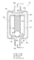
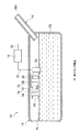
図1には、本発明の第1実施形態の燃料タンク構造12が示されている。また、図2〜図4には、この燃料タンク構造12を構成する内圧制御バルブ32が断面図にて示されている。
FIG. 1 shows a
燃料タンク構造12は、内部に燃料を収容可能な燃料タンク14を有している、燃料タンクの上部には、給油配管16の下端部分が接続されている。給油配管16の上端の開口部分は給油口16Hとされている。給油口16Hに給油ガンを差し入れて、燃料タンク14に給油することができる。
The
燃料タンク14の外部には、内部に活性炭等の吸着剤が収容されたキャニスタ18が備えられている。燃料タンク14の内部の気体層とキャニスタ18とは共通配管20で接続されており、燃料タンク14内の気体をキャニスタ18に流入させることができる。流入された気体中の蒸発燃料は、キャニスタ18の吸着剤で吸着され、それ以外の気体(大気成分)が、大気連通管22から大気中に排出される。
A
共通配管20の下端には、燃料タンク14内の上部に位置するように、満タン規制バルブ24が設けられている。満タン規制バルブ24は、いわゆるフロートバルブであり、燃料FEに浮遊する図示しないフロートを有している。燃料タンク14内の燃料FEの液面が満タン液位FLに達するまでは、フロートは燃料に浮くことはないが、燃料FEが満タン液位FLに達すると、満タン規制バルブ24のフロートが燃料FEに浮き、満タン規制バルブ24は閉弁状態となる。この状態では、共通配管20も閉塞されるので、共通配管20を通じての燃料タンク14からキャニスタ18への気体の移動は阻止される。
A full
満タン規制バルブ24の上部からは、分岐配管26が延出されている。本実施形態では、後述するカットオフバルブ28から分岐配管26及び共通配管20を経てキャニスタ18まで気体の移動が可能とされている。
A
分岐配管26の先端(下端)には、カットオフバルブ28が備えられている。カットオフバルブ28は、燃料タンク14内において、満タン規制バルブ24よりも高い位置に設けられている。カットオフバルブ28は、燃料タンク14のタンク内圧が上昇して所定値を超えると開弁され、燃料タンク14内の気体をキャニスタ18に流入可能とする。たとえば、満タン規制バルブ24が閉弁されていても、カットオフバルブ28が開弁されることで、燃料タンク14内の気体がキャニスタ18に移動可能となる。これにより、燃料タンク14のタンク内圧の過度の上昇が抑制される。
A cut-off
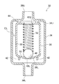
分岐配管26の中間位置(カットオフバルブ28からキャニスタ18までの間)には、内圧制御バルブ32が設けられている。図2にも詳細に示すように、内圧制御バルブ32は、略円筒状に形成されたバルブハウジング34を有している。バルブハウジング34の上壁34Uに形成された上部開口36Uはキャニスタ18側に位置し、下壁34Lに形成された下部開口36Lは燃料タンク14側に位置するように、バルブハウジング34は分岐配管26に取り付けられている。
An internal
バルブハウジング34の内部には、第1バルブ体38が収容されている。第1バルブ体38は略円筒状に形成されており、バルブハウジング34の内周面と第1バルブ体38の外周面との間には所定の隙間CLが構成されている。第1バルブ体38は、バルブハウジング34内において、上下に移動可能となっている。第1バルブ体38は、本発明のバルブ部材の一例である。
A
第1バルブ体38の上壁38Uには、バルブハウジング34の上部開口36Uに臨む上部開口40Uが形成されている。同様に、第1バルブ体38の下壁38Lは、バルブハウジング34の下部開口36Lに臨む下部開口40Lが形成されている。
An
バルブハウジング34の上壁34Uの下面には、第1バルブ体38の上面と対向する環状のシール部44が形成されている。第1バルブ体38が上昇してシール部44に全周にわたって接触すると、隙間CLと上部開口36Uとの間での気体の移動が阻止される。
An
第1バルブ体38の下壁38Lからは、下方に突出する複数本の脚部42が形成されている。脚部42は、第1バルブ体38の周方向には所定の間隔をあけて形成されている。脚部42は、第1バルブ体38が下降したときにバルブハウジング34の下壁34Lに接触する。ただし、この状態においても、隙間CLと下部開口36Lとの気体の移動が可能となっている。
A plurality of
第1バルブ体38の内部には、第2バルブ体48が収容されている。第2バルブ体48は、たとえば略球状に形成されて、その外径(図2における幅)が、第1バルブ体38の内径よりも小さくされており、第1バルブ体38内で上下に移動することが可能となっている。第1バルブ体38の内部には、圧縮コイルスプリング52が収容されている。圧縮コイルスプリング52は、所定のバネ力で第2バルブ体48を下部開口40Lに向かって押圧している。
A
第2バルブ体48の外径は、第1バルブ体38の下部開口40Lよりも大径とされており、第1バルブ体38内で降下すると、下部開口40Lの口縁に全周で接触する。これにより、下部開口40Lを通じての気体の移動が阻止される。
The outer diameter of the
第1バルブ体38の下壁38Lの上面は、下部開口40Lに向かって逆円錐状に傾斜する傾斜面46とされている。傾斜面46によって、第2バルブ体48は降下時に下部開口40Lの中心に案内される。
The upper surface of the
第1バルブ体38と第2バルブ体48及び圧縮コイルスプリング52を合わせた質量は、燃料タンク14内が満タン状態となって満タン規制バルブ24が閉弁された状態で、燃料タンク14内の気体の流れが下部開口36Lから作用したときに、第1バルブ体38及び第2バルブ体48が上昇するように、所定の質量とされている。そして、燃料タンク14から作用する圧力が低下し、所定の開弁圧になったときに、第1バルブ体38が降下してシール部44から離間するように、所定の開弁圧に設定されている、
The mass of the
また、第2バルブ体48が第1バルブ体38に対し上昇して下部開口40Lの口縁から離間するときの圧力(第2バルブ体48が開弁されるときの開弁圧)は、給油配管16内に溜まった燃料のヘッド圧と同程度あるいは、このヘッド圧よりもわずかに低い程度とされている。
Further, the pressure when the
第1バルブ体38の側面には、小孔状(たとえば直径が0.5mm以下の円形の孔)のオリフィス50が形成されている。オリフィス50により、第1バルブ体38の内部と外部(ただしバルブハウジング34の内部、すなわち隙間CL)との間の気体の移動が許容される。ただし、オリフィス50は小孔状とされているため、この気体の移動には、所定の抵抗が生じる。
An
次に、本実施形態の燃料タンク構造12の作用を説明する。
Next, the operation of the
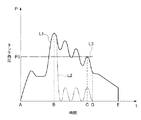
燃料タンク14に給油する場合には、給油配管16の上端の給油口16Hに図示しない給油ガンを差し入れる。給油中は、燃料タンク14のタンク内圧が燃料タンク14内の燃料量や満タン規制バルブ24の状態等に応じて変化する。図5には、給油開始時からの時間tの経過に伴う燃料タンク14のタンク内圧Pの変化が定性的に示されている。このグラフにおいて、給油配管16内を上昇して給油ガンに達した燃料のヘッド圧(P1)を一点鎖線L3で示している。
When refueling the
燃料タンク14内の燃料FEの液面が満タン液位FLに達するまで(図5におけるA〜Bの時間)は、満タン規制バルブ24は開弁されている、燃料タンク14内の気体はキャニスタ18に移動するため、燃料タンク14に引き続き給油することが可能である。この状態では、図2に示すように、内圧制御バルブ32の第1バルブ体38は降下している。
Until the liquid level of the fuel FE in the
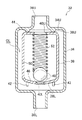
燃料タンク14内の燃料FEの液面が満タン液位FLに達すると(図5おけるBの時点)、満タン規制バルブ24が閉弁されるので、燃料タンク14のタンク内圧Pが短時間で上昇する。この状態で、カットオフバルブ28は開弁されており、燃料タンク14内の圧力は(実質的に流速の速い気体として)内圧制御バルブ32に作用する。このため、満タン状態あるいは満タン状態になる直前において、図3に示すように、内圧制御バルブ32の第1バルブ体38が上昇し、シール部44に接触する。分岐配管26を通じての燃料タンク14からキャニスタ18への気体の移動が制限される。給油された燃料は給油配管16内を上昇し、給油ガンに達する。そして、給油ガンのオートストップ機構が働くことで、給油が止められる。
When the level of the fuel FE in the
ここで、燃料タンク14のタンク内圧Pは、給油配管16におけるヘッド圧と同程度に維持される。すなわち、燃料タンク14のタンク内圧Pが急激に降下することがなく、給油配管16内において、給油ガンに接触する液面位置を維持できる。給油ガンのオートストップ機構は引き続き働くので、いわゆる過給油にならない。
Here, the tank internal pressure P of the
この状態で、オリフィス50を通じて、僅かずつではあるが燃料タンク14内の気体がキャニスタ18に移動する。したがって、図5におけるB〜Eの時間では、燃料タンク14のタンク内圧Pが漸減している。
In this state, the gas in the
また、燃料タンク14内のタンク内圧Pのわずかな変動(上昇)等に伴い、内圧制御バルブ32の第2バルブ体48が上昇して下部開口40Lの口縁から離れると、燃料タンク14から分岐配管26を通じて気体がキャニスタ18に移動し、燃料タンク14のタンク内圧が降下する。これにより、第2バルブ体48も降下するので、下部開口40Lの口縁に再び接触し、気体のキャニスタ18への移動が阻止される。すなわち、図4において、実線及び二点鎖線で示すように、第2バルブ体48が下部開口40Lの口縁への接触と離間とを繰り返す(図5におけるB〜Cの時間)。
Further, when the
したがって、図5におけるB〜Dの時間では、タンク内圧Pは、上下に変動しつつ、この時間全体ではゆるやかに降下している。 Therefore, the tank internal pressure P fluctuates up and down during the period from B to D in FIG.
ここで、図5には、比較例における燃料タンクのタンク内圧Pの定性的な経時変化も、二点鎖線L2で併せて示されている。比較例の燃料タンク構造では、本実施形態の第1バルブ体38を有さない構造であるが、これ以外は本実施形態と同じ構造とされている。したがって、第2バルブ体48の上下動により、バルブハウジング34の下部開口36Lが開閉される。
Here, in FIG. 5, the qualitative temporal change of the tank internal pressure P of the fuel tank in the comparative example is also shown by a two-dot chain line L2. The fuel tank structure of the comparative example is a structure that does not have the
比較例の燃料タンク構造では、第2バルブ体48の上下動に伴い、燃料タンク14のタンク内圧Pが上下している。しかしながら、分岐配管26を通じて燃料タンク14からキャニスタ18への気体の移動を積極的に制限する(そのような所定の抵抗を生じさせる)構造ではないため、Bの時点から短時間でタンク内圧が降下し、給油配管16のヘッド圧P1よりも低くなっている。
In the fuel tank structure of the comparative example, the tank internal pressure P of the
これに対し、本実施形態の燃料タンク構造12では、燃料タンク14のタンク内圧Pが徐々に降下するため、給油配管16のヘッド圧P1よりもタンク内圧Pが高い状態を、より長時間にわたって維持できる(図5におけるB〜Cの時間)。給油配管16内では、燃料が給油ガンに達した状態を維持でき、オートストップ機構が継続するので、いわゆる過給油を抑制する効果が、たとえば比較例の燃料タンク構造よりも高くなる。
On the other hand, in the
なお、この時間(B〜Cの時間)において、一時的に燃料タンク14のタンク内圧Pがヘッド圧P1よりも小さくなる状態が存在していても、短時間であれば、給油配管16内の燃料が燃料タンク14内に流下することはない。換言すれば、このように、給油配管16内の燃料が燃料タンク14内に流下しない程度であれば、燃料タンク14のタンク内圧Pが、給油配管16におけるヘッド圧P1に維持されていることになる。
In this time (time B to C), even if there is a state in which the tank internal pressure P of the
そして、燃料タンク14のタンク内圧が所定値以下になると、第1バルブ体38が降下する。脚部42がバルブハウジング34の下壁34Lに接触し、内圧制御バルブ32(分岐配管26)を通じて、燃料タンク14内の気体がキャニスタ18に移動可能な状態となる(図5におけるEの時点)。
And if the tank internal pressure of the
以降は、内圧制御バルブ32は常時開弁されている(カットオフバルブ28も開弁されている)ので、たとえば、キャニスタ18に備えられたOBDポンプ(故障診断用のポンプ)を駆動して燃料タンク14に所定の圧力を作用させ、燃料タンク14の不具合検知を行うことが可能である。
Thereafter, since the internal
図6には、本発明の第2実施形態の燃料タンク構造72が示されている。第2実施形態では、2つのカットオフバルブ28を有している。そして、これら2つのカットオフバルブ28のそれぞれに接続された分岐配管74が合流部76で合流され、さらに、カットオフバルブ28まで分岐配管26で接続されている(分岐配管74も分岐配管26の一部を成している)。2つのカットオフバルブ28は互いに対等な関係にあるが、燃料タンク14に対する位置が異なっている。これ以外は、第2実施形態の燃料タンク構造72は、第1実施形態の燃料タンク構造12と同一構成とされている。
FIG. 6 shows a
したがって、第2実施形態の燃料タンク構造72においても、第1実施形態の燃料タンク構造12と略同様の作用効果を奏する。さらに、第2実施形態の燃料タンク構造72では、異なる位置に設けられた2つのカットオフバルブ28を有しているため、燃料タンク14内の液面の傾斜等によって一方のカットオフバルブ28が液没しても、他方のカットオフバルブ28は液没しない状態を維持する可能性が高くなる。
Therefore, the
なお、このように、燃料タンク14内の液面傾斜時にカットオフバルブ28の液没を防止する観点からは、3つ以上のカットオフバルブ28を備える構成としてもよい。
In this way, from the viewpoint of preventing the cut-off
上記では、本発明の内圧制御バルブとして、バルブハウジング34内に第1バルブ体38を備えると共に、さらに第1バルブ体38内に第2バルブ体48を備えた構成を挙げているが、内圧制御バルブの具体的構成はこれに限定されない。要するに、燃料タンク14の満タン状態(満タン規制バルブ24の閉弁状態)で、分岐配管26の流路抵抗を大きくする等により燃料タンク14からキャニスタ18への気体の移動を抑制し、燃料タンク14のタンク内圧を給油配管16のヘッド圧に所定時間維持できればよい。
In the above description, the internal pressure control valve of the present invention has a configuration in which the
また、オリフィス50が形成されていない構造の内圧制御バルブとしても、燃料タンク14のタンク内圧を、給油配管16のヘッド圧に維持することは可能である。ただし、オリフィス50による気体の移動はないため、第2バルブ体48の上下動のみで燃料タンク14のタンク内圧を降下させて、内圧制御バルブを開弁状態にする必要がある(必要以上に長い時間を要すると共に、その制御も難しくなる)。これに対し、オリフィス50を有する構成では、オリフィス50を通じて燃料タンク14内の気体を単位時間当たり所定量でキャニスタ18に移動させるので、必要以上に時間を要することなく、しかも確実にタンク内圧を降下させ、内圧制御バルブ32を開弁状態に移行させることができる。
Further, even if the internal pressure control valve has a structure in which the
12 燃料タンク構造
14 燃料タンク
16 給油配管
18 キャニスタ
20 共通配管
24 満タン規制バルブ
26 分岐配管
28 カットオフバルブ
32 内圧制御バルブ
38 第1バルブ体
48 第2バルブ体
50 オリフィス
72 燃料タンク構造
FE 燃料
FL 満タン液位
12
Claims (2)
前記燃料タンク内の蒸発燃料を吸着剤により吸着可能なキャニスタと、
前記燃料タンク内に設けられ、前記燃料タンク内の燃料液面があらかじめ設定された満タン液位に達すると閉弁する満タン規制バルブと、
前記満タン規制バルブと前記キャニスタとを連通する共通配管と、
前記満タン規制バルブの上部から分岐し前記燃料タンク内に位置する分岐配管と、
前記燃料タンクから前記満タン液位よりも高い位置まで延出されて燃料タンクへの給油用とされる給油配管と、
前記分岐配管に設けられたバルブハウジングと、
前記バルブハウジング内に前記バルブハウジングと隙間をあけて配置され、前記燃料タンクが満タンになった状態で燃料タンクのタンク内圧を受けて前記バルブハウジング内の気体移動を許容する位置から上昇すると前記バルブハウジングの上部開口を閉塞し前記バルブハウジング内の該気体移動を制限する第1バルブ体と、
前記第1バルブ体内で前記第1バルブ体の下部開口を閉塞すると共に前記燃料タンクのタンク内圧を受けて上昇すると前記下部開口を開放し前記第1バルブ体内を通じて前記バルブハウジングの前記上部開口に抜ける気体移動を許容する第2バルブ体と、
前記第1バルブ体に設けられ前記第2バルブ体が前記下部開口を閉塞した状態で前記第1バルブ体の内部と前記隙間との気体移動に対し抵抗を作用させつつ該気体移動を許容するオリフィスと、
を有する燃料タンク構造。 A fuel tank capable of containing fuel, and
A canister capable of adsorbing evaporated fuel in the fuel tank by an adsorbent;
A full tank regulating valve which is provided in the fuel tank and closes when a fuel level in the fuel tank reaches a preset full liquid level;
A common pipe communicating the full tank regulating valve and the canister;
A branch pipe branched from the upper part of the full tank regulating valve and located in the fuel tank;
A fuel supply pipe extending from the fuel tank to a position higher than the full tank liquid level and used for fuel supply to the fuel tank;
A valve housing provided in the branch pipe;
The valve housing is disposed with a gap with the valve housing, and when the fuel tank is full, when the tank is filled from a position allowing gas movement in the valve housing by receiving the tank internal pressure, A first valve body that closes an upper opening of the valve housing and restricts the movement of the gas in the valve housing;
When the lower opening of the first valve body is closed in the first valve body and rises due to the tank internal pressure of the fuel tank, the lower opening is opened and the first valve body passes through the upper opening of the valve housing. A second valve body that allows gas movement;
An orifice that is provided in the first valve body and allows the gas movement while applying resistance to the gas movement between the inside of the first valve body and the gap in a state where the second valve body closes the lower opening. When,
Having fuel tank structure.
を有する請求項1に記載の燃料タンク構造。 Wherein in the fuel tank at a position higher than the full fluid level is provided in the branch pipe, the cut-off valve the tank pressure of the fuel tank opens the branch pipe by opening exceeds a predetermined value,
The fuel tank structure according to claim 1, comprising:
Priority Applications (2)
| Application Number | Priority Date | Filing Date | Title |
|---|---|---|---|
| JP2011115921A JP5413402B2 (en) | 2011-05-24 | 2011-05-24 | Fuel tank structure |
| US13/456,938 US9079488B2 (en) | 2011-05-24 | 2012-04-26 | Fuel tank structure |
Applications Claiming Priority (1)
| Application Number | Priority Date | Filing Date | Title |
|---|---|---|---|
| JP2011115921A JP5413402B2 (en) | 2011-05-24 | 2011-05-24 | Fuel tank structure |
Publications (2)
| Publication Number | Publication Date |
|---|---|
| JP2012240650A JP2012240650A (en) | 2012-12-10 |
| JP5413402B2 true JP5413402B2 (en) | 2014-02-12 |
Family
ID=47218494
Family Applications (1)
| Application Number | Title | Priority Date | Filing Date |
|---|---|---|---|
| JP2011115921A Expired - Fee Related JP5413402B2 (en) | 2011-05-24 | 2011-05-24 | Fuel tank structure |
Country Status (2)
| Country | Link |
|---|---|
| US (1) | US9079488B2 (en) |
| JP (1) | JP5413402B2 (en) |
Families Citing this family (1)
| Publication number | Priority date | Publication date | Assignee | Title |
|---|---|---|---|---|
| EP4006330A4 (en) * | 2019-07-30 | 2022-11-23 | Mitsubishi Jidosha Kogyo Kabushiki Kaisha | FUEL TANK SYSTEM |
Family Cites Families (11)
| Publication number | Priority date | Publication date | Assignee | Title |
|---|---|---|---|---|
| JPH07290981A (en) * | 1994-04-26 | 1995-11-07 | Toyoda Gosei Co Ltd | Fuel vapor collection control valve gear |
| US5590697A (en) * | 1994-08-24 | 1997-01-07 | G. T. Products, Inc. | Onboard vapor recovery system with two-stage shutoff valve |
| IL114959A0 (en) * | 1995-08-16 | 1995-12-08 | Aran Eng Dev Ltd | Over filling valve |
| US5782258A (en) * | 1995-12-11 | 1998-07-21 | Alfmeier Corporation | Vapor recovery fuel tank system |
| US6405747B1 (en) * | 1999-10-29 | 2002-06-18 | Stant Manufacturing, Inc. | Fuel tank vent valve with liquid carryover filter |
| US6655403B2 (en) * | 2002-01-08 | 2003-12-02 | Eaton Corporation | Controlling fuel vapor venting in a fuel tank |
| JP4058617B2 (en) * | 2002-07-22 | 2008-03-12 | 株式会社ニフコ | Combined air vent valve and air vent mechanism for fuel tank |
| JP4035022B2 (en) * | 2002-09-11 | 2008-01-16 | 本田技研工業株式会社 | Evaporative fuel processing equipment |
| US7234452B2 (en) * | 2004-12-20 | 2007-06-26 | Eaton Corporation | Controlling vapor emission in a small engine fuel tank system |
| JP2010173467A (en) | 2009-01-29 | 2010-08-12 | Yachiyo Industry Co Ltd | Ventilation control valve |
| JP2012047169A (en) | 2010-07-30 | 2012-03-08 | Toyoda Gosei Co Ltd | Fuel tank valve device and fuel tank ventilation device |
-
2011
- 2011-05-24 JP JP2011115921A patent/JP5413402B2/en not_active Expired - Fee Related
-
2012
- 2012-04-26 US US13/456,938 patent/US9079488B2/en not_active Expired - Fee Related
Also Published As
| Publication number | Publication date |
|---|---|
| US20120298534A1 (en) | 2012-11-29 |
| US9079488B2 (en) | 2015-07-14 |
| JP2012240650A (en) | 2012-12-10 |
Similar Documents
| Publication | Publication Date | Title |
|---|---|---|
| US9494325B2 (en) | Fuel tank structure | |
| CN103442920B (en) | Cross fuel feeding and prevent valve | |
| US8485214B2 (en) | Small engine emissions control valve | |
| CN105736774B (en) | Flow control valve and evaporated fuel treating apparatus | |
| CN101332769A (en) | A recovery device and recovery method for vehicle-mounted gasoline vapor | |
| JP2006097674A (en) | Fuel cut-off valve | |
| JP2012047169A (en) | Fuel tank valve device and fuel tank ventilation device | |
| JP5413402B2 (en) | Fuel tank structure | |
| US20150306951A1 (en) | Fuel tank structure | |
| JP5888302B2 (en) | Valve and fuel tank structure | |
| JP6945310B2 (en) | Fuel tank system | |
| JP2006051928A (en) | Air intake device of air filter for canister | |
| JP2011102098A (en) | Fuel shut-off valve | |
| CN211203005U (en) | A slope exhaust valve | |
| US12090837B2 (en) | Over-fueling prevention valve | |
| JP5428993B2 (en) | Supercharging prevention device | |
| JP2010100117A (en) | Float valve device | |
| JP6060609B2 (en) | Ventilation control valve device | |
| JP6384456B2 (en) | Fuel tank system | |
| JP2010173397A (en) | Fuel shutoff valve | |
| JP4318937B2 (en) | Evaporative fuel processing equipment | |
| JP2006097599A (en) | Fuel shut-off valve | |
| KR100535512B1 (en) | Fuel pressure reduction device | |
| JP2004300939A (en) | Fuel outflow regulating device of fuel tank | |
| JP2008064016A (en) | Valve device for fuel tank |
Legal Events
| Date | Code | Title | Description |
|---|---|---|---|
| A977 | Report on retrieval |
Free format text: JAPANESE INTERMEDIATE CODE: A971007 Effective date: 20130425 |
|
| A131 | Notification of reasons for refusal |
Free format text: JAPANESE INTERMEDIATE CODE: A131 Effective date: 20130507 |
|
| A521 | Request for written amendment filed |
Free format text: JAPANESE INTERMEDIATE CODE: A523 Effective date: 20130625 |
|
| TRDD | Decision of grant or rejection written | ||
| A01 | Written decision to grant a patent or to grant a registration (utility model) |
Free format text: JAPANESE INTERMEDIATE CODE: A01 Effective date: 20131015 |
|
| A61 | First payment of annual fees (during grant procedure) |
Free format text: JAPANESE INTERMEDIATE CODE: A61 Effective date: 20131028 |
|
| R151 | Written notification of patent or utility model registration |
Ref document number: 5413402 Country of ref document: JP Free format text: JAPANESE INTERMEDIATE CODE: R151 |
|
| LAPS | Cancellation because of no payment of annual fees |