JP5413229B2 - Liquid ejector - Google Patents
Liquid ejector Download PDFInfo
- Publication number
- JP5413229B2 JP5413229B2 JP2010028624A JP2010028624A JP5413229B2 JP 5413229 B2 JP5413229 B2 JP 5413229B2 JP 2010028624 A JP2010028624 A JP 2010028624A JP 2010028624 A JP2010028624 A JP 2010028624A JP 5413229 B2 JP5413229 B2 JP 5413229B2
- Authority
- JP
- Japan
- Prior art keywords
- pressure
- ink
- liquid
- ejection head
- ejection
- Prior art date
- Legal status (The legal status is an assumption and is not a legal conclusion. Google has not performed a legal analysis and makes no representation as to the accuracy of the status listed.)
- Active
Links
Images


Description
本発明は、噴射ヘッドから液体を噴射する技術に関する。 The present invention relates to a technique for ejecting liquid from an ejection head.
いわゆるインクジェットプリンターでは、微細な噴射ノズルから、正確な分量のインク
を正確な位置に噴射することによって、高画質の画像を印刷することが可能である。また
、この技術を利用して、インクの代わりに各種の液体を基板に向けて噴射すれば、電極や
、センサ、バイオチップなどを製造することも可能である。
A so-called inkjet printer can print a high-quality image by ejecting an accurate amount of ink to a precise position from a fine ejection nozzle. In addition, by utilizing this technique and ejecting various liquids instead of ink toward the substrate, it is also possible to manufacture electrodes, sensors, biochips, and the like.
このような技術では、噴射ノズルを備えた噴射ヘッドを用いてインクなどの液体を噴射
する。噴射ヘッド内の液体が増粘するなどして性状が劣化してしまった場合には、噴射ノ
ズルをキャップで覆った状態でキャップに接続された吸引ポンプを作動させることで、性
状の劣化した液体を噴射ノズルから吸引する動作である吸引クリーニングを行う。また、
吸引クリーニングを行うに際しては、キャップを噴射ヘッドに押し当てることでキャップ
と噴射ヘッドとの間に密閉空間を形成しなければならず、その為には、キャップを噴射ノ
ズルの正確な位置に当接させる必要があるが、このことは必ずしも容易なことではない。
そこで、吸引クリーニングに替えて、噴射ヘッドを上流側から加圧することで噴射ヘッド
内の液体を押し出してキャップに排出する動作である加圧クリーニングを実行し、噴射ノ
ズルをキャップで覆う動作を省略可能とすることが行われることもある。
In such a technique, a liquid such as ink is ejected by using an ejection head having an ejection nozzle. If the properties in the jet head have increased due to thickening, etc., the liquid with degraded properties can be obtained by operating the suction pump connected to the cap with the jet nozzle covered with the cap. Suction cleaning, which is an operation of sucking the air from the spray nozzle, is performed. Also,
When performing suction cleaning, it is necessary to form a sealed space between the cap and the ejection head by pressing the cap against the ejection head. For this purpose, the cap is brought into contact with the exact position of the ejection nozzle. This is not always easy.
Therefore, instead of suction cleaning, pressurization cleaning, which is an operation to push the liquid in the ejection head by pressing it from the upstream side and discharge it to the cap, can be omitted, and the operation to cover the ejection nozzle with the cap can be omitted Sometimes it is done.
また、噴射ヘッドは液体を加圧することによって噴射しているので、正確な分量の液体
を噴射する為には、噴射ヘッドに供給される液体の圧力を適正な圧力に保っておく必要が
ある。ところが、液体を噴射ヘッドに供給するための通路で圧力損失が生じる影響で、噴
射ヘッドに供給される液体の圧力を一定に保っておくことは難しい。そこで、噴射ヘッド
までは加圧によって液体を供給しておき、噴射ヘッド内の圧力が所定圧力を下回った場合
には、圧力調整弁を開いて必要量の液体を供給することで、噴射ヘッドに供給する液体の
圧力を適切な圧力に調整する技術が提案されている。(特許文献1)
Further, since the ejection head ejects the liquid by pressurizing the liquid, it is necessary to keep the pressure of the liquid supplied to the ejection head at an appropriate pressure in order to eject an accurate amount of liquid. However, it is difficult to keep the pressure of the liquid supplied to the ejection head constant due to the effect of pressure loss in the passage for supplying the liquid to the ejection head. Therefore, the liquid is supplied up to the ejection head by pressurization, and when the pressure in the ejection head falls below a predetermined pressure, the pressure adjustment valve is opened to supply the required amount of liquid to the ejection head. A technique for adjusting the pressure of the liquid to be supplied to an appropriate pressure has been proposed. (Patent Document 1)
しかし、圧力調整弁によって噴射ヘッドに供給される液体の圧力を一定に保とうとする
と、加圧クリーニングを行うことができず、その結果、吸引クリーニングを行わざるを得
ないという問題があった。すなわち、圧力調整弁は、異なる圧力によって噴射ヘッドに液
体が供給されることが無いように、圧力調整弁の上流側から加圧されても弁が開かない構
造となっている。従って、噴射ヘッドを上流側から加圧しても圧力調節弁によって加圧力
が遮られてしまい、吸引クリーニングよりも簡便な加圧クリーニングを実行することがで
きなくなってしまうという問題があった。
However, if the pressure of the liquid supplied to the ejection head is kept constant by the pressure regulating valve, there is a problem that pressure cleaning cannot be performed, and as a result, suction cleaning must be performed. That is, the pressure regulating valve has a structure in which the valve does not open even when pressurized from the upstream side of the pressure regulating valve so that liquid is not supplied to the ejection head by different pressures. Therefore, there is a problem that even if the ejection head is pressurized from the upstream side, the applied pressure is blocked by the pressure control valve, and pressure cleaning that is simpler than suction cleaning cannot be performed.
この発明は、従来の技術が有する上述した課題を解決するためになされたものであり、
噴射ヘッドに供給される液体の圧力を圧力調整弁によって一定に保つと共に、加圧クリー
ニングを実行可能な技術の提供を目的とする。
The present invention has been made to solve the above-described problems of the prior art,
An object of the present invention is to provide a technique capable of performing pressure cleaning while keeping the pressure of the liquid supplied to the ejection head constant by a pressure regulating valve.
上述した課題の少なくとも一部を解決するために、本発明の液体噴射装置は次の構成を採用した。すなわち、
噴射ヘッドに設けられた噴射ノズルから液体を噴射する液体噴射装置であって、
前記噴射ノズルから噴射する液体を、液体流路を介して前記噴射ヘッドに向けて圧送する液体供給部と、
前記液体供給部と前記噴射ヘッドとの間の前記液体流路に設けられた圧力調整手段であって、該圧力調整手段と前記噴射ヘッドとの間の液体の圧力が所定の圧力範囲になったときのみに開弁する圧力調整弁を有する圧力調整手段と、
前記圧力調整弁の上流側と下流側とを接続するバイパス通路を開いて、前記液体供給部から圧送された液体を前記噴射ヘッドに導くことにより、該噴射ヘッド内の液体を前記噴射ノズルから排出させるクリーニング動作を行う加圧クリーニング手段と
を備えることを要旨とする。
In order to solve at least a part of the problems described above, the liquid ejecting apparatus of the present invention employs the following configuration. That is,
A liquid ejecting apparatus that ejects liquid from an ejection nozzle provided in an ejection head,
A liquid supply unit that pumps the liquid ejected from the ejection nozzle toward the ejection head via a liquid flow path ;
Pressure adjusting means provided in the liquid flow path between the liquid supply unit and the ejection head, and the pressure of the liquid between the pressure adjustment means and the ejection head is within a predetermined pressure range. Pressure regulating means having a pressure regulating valve that opens only when,
By opening a bypass passage connecting the upstream side and the downstream side of the pressure regulating valve and guiding the liquid pressure-fed from the liquid supply unit to the ejection head, the liquid in the ejection head is discharged from the ejection nozzle. And a pressure cleaning means for performing the cleaning operation.
このような本発明の液体噴射装置においては、液体圧送手段によって圧送されてきた液
体が、圧力調整手段と噴射ヘッドとの間の液体の圧力が所定の圧力範囲になったときにの
み噴射ヘッドに供給される。このため、液体を圧送する際の流路抵抗の違いによって供給
される圧力に変動が生じた場合でも、噴射ヘッド内の液体の圧力を一定圧力に保っておく
ことができ、適切に液体を噴射することができる。もっとも、この様に圧力調整手段を備
えた構成では、噴射ヘッド内の加圧クリーニングを行うために噴射ヘッドに向けて液体を
圧送した場合でも、圧送した液体の圧力では圧力調整弁が開かないため、液体圧送手段の
加圧力によって噴射ヘッド内の液体を噴射ノズルから排出させてクリーニングする加圧ク
リーニングを行うことができない。そこで、本発明の液体噴射装置では、圧力調整手段の
上流側と下流側を接続するバイパス経路が設けられており、加圧クリーニングを行う際に
は、バイパス通路を開いて、液体圧送手段から圧送された液体を直接に噴射ヘッドに導く
ことが可能となっている。
In such a liquid ejecting apparatus of the present invention, the liquid pumped by the liquid pumping means is applied to the ejecting head only when the pressure of the liquid between the pressure adjusting means and the ejecting head falls within a predetermined pressure range. Supplied. For this reason, even when fluctuations occur in the pressure supplied due to the difference in flow path resistance when liquid is pumped, the liquid pressure in the ejection head can be maintained at a constant pressure, and the liquid is ejected appropriately. can do. However, in the configuration provided with the pressure adjusting means in this way, even when liquid is pumped toward the jet head to perform pressure cleaning in the jet head, the pressure regulating valve does not open with the pressure of the pumped liquid. Therefore, it is impossible to perform pressure cleaning in which the liquid in the ejection head is discharged from the ejection nozzle and cleaned by the pressure applied by the liquid pressure feeding means. Therefore, in the liquid ejecting apparatus of the present invention, a bypass path that connects the upstream side and the downstream side of the pressure adjusting means is provided, and when performing pressure cleaning, the bypass passage is opened and the pressure feeding means from the liquid pressure feeding means. It is possible to directly guide the liquid to the ejection head.
こうすれば、圧力調整手段を備えながら、加圧クリーニングを実行することが可能とな
る。従って、吸引クリーニングを行わなくても、性状が劣化した液体を噴射ヘッドの外に
排出するメンテナンス動作を行うことが可能となり、その結果として、吸引クリーニング
時には必要な動作であるキャップを噴射ノズルの正確な位置に当接させる動作を省略する
ことができるので、メンテナンス動作を簡単にすることが可能となる。また、加圧クリー
ニングを行わない状態では、バイパス通路を閉じておけば、圧送された液体は圧力調整手
段を介して噴射ヘッドに供給されるので、噴射ヘッドに供給される液体の圧力を一定に保
つことが可能となる。
In this way, it is possible to perform pressure cleaning while providing the pressure adjusting means. Accordingly, it is possible to perform a maintenance operation for discharging the liquid having deteriorated properties outside the ejection head without performing the suction cleaning, and as a result, the cap, which is a necessary operation during the suction cleaning, is attached to the ejection nozzle accurately. Since it is possible to omit the operation of making contact with the correct position, the maintenance operation can be simplified. Further, in a state where pressure cleaning is not performed, if the bypass passage is closed, the pressure-fed liquid is supplied to the ejecting head via the pressure adjusting means, so that the pressure of the liquid supplied to the ejecting head is kept constant. It becomes possible to keep.
また、上述した本発明の液体噴射装置においては、加圧クリーニングを行う際には、加圧クリーニングを行っていない状態よりも高い圧力によって、液体供給部から噴射ヘッドに向けて液体を圧送することとしてもよい。 In the above-described liquid ejecting apparatus of the present invention, when pressure cleaning is performed, the liquid is pumped from the liquid supply unit toward the ejecting head with a pressure higher than that in a state where pressure cleaning is not performed. It is good.
こうすれば、加圧クリーニング時に噴射ヘッドに圧送される液体の圧力を高めることで
、より大きな圧力によって噴射ヘッド内の液体を押し出すことができるので、性状が劣化
した液体の排出能力を高めることが可能となる。また、加圧クリーニングを行っていない
状態にまで高い圧力によって液体が圧送されることがないので、液体を圧送する液体圧送
手段に対して、余分な圧力負荷がかかることを回避することが可能となる。
In this way, by increasing the pressure of the liquid pumped to the ejection head at the time of pressure cleaning, the liquid in the ejection head can be pushed out by a larger pressure, so that the discharge capability of the liquid with deteriorated properties can be increased. It becomes possible. In addition, since the liquid is not pumped by a high pressure even when pressure cleaning is not performed, it is possible to avoid applying an extra pressure load to the liquid pumping means for pumping the liquid. Become.
以下では、上述した本願発明の内容を明確にするために、次のような順序に従って実施
例を説明する。
A.装置構成:
B.本実施例のインク供給方法:
C.変形例:
Hereinafter, in order to clarify the contents of the present invention described above, examples will be described in the following order.
A. Device configuration:
B. Ink supply method of this embodiment:
C. Variations:
A.装置構成 :
図1は、ラインプリンター1を例に用いて本実施例の液体噴射装置の大まかな構造を示
した説明図である。図示されているように、本実施例のラインプリンター1は、大まかに
は箱型の外形形状をしており、上面には、モニターパネル2や、ユーザーが操作するため
の操作パネル3などが設けられている。また、ラインプリンター1の前面には、インクカ
ートリッジを交換する際に開けるカートリッジ交換扉4や、印刷用紙を装填する際に開け
る給紙扉5が設けられており、更に、向かって右側面には、印刷された印刷用紙が排出さ
れる排紙口6が設けられている。
A. Device configuration :
FIG. 1 is an explanatory diagram showing a rough structure of a liquid ejecting apparatus according to the present embodiment using a line printer 1 as an example. As shown in the figure, the line printer 1 of the present embodiment has a box-like outer shape, and a
ラインプリンター1の内部には、各種の機能を実行する複数のユニットあるいは部品が
搭載されている。先ず、ラインプリンター1のほぼ中央の位置には、印刷用紙にインクを
噴射するヘッドユニット30が設けられている。ヘッドユニット30の下方には、ヘッド
ユニット30にインクを供給するインク供給部60が設けられており、インク供給部60
には、インクが充填されたインクカートリッジ62が装着される。尚、本実施例のライン
プリンター1では、黒インク(Kインク)、シアンインク(Cインク)、マゼンタインク
(Mインク)、イエローインク(Yインク)の4色のインクを印刷に使用することが可能
であり、このことに対応して、インク供給部60には、各色のインクが充填された4つの
インクカートリッジ62が装着されるようになっている。
Inside the line printer 1, a plurality of units or parts for executing various functions are mounted. First, a
Is mounted with an
図1の紙面上で、ヘッドユニット30の左下の位置には、印刷用紙が装填される給紙カ
セット10が設けられており、給紙カセット10の右端の上面に接する位置に、給紙ロー
ラー20が設けられている。更に、給紙ローラー20の奥側には給紙モーター22が接続
されており、給紙モーター22を駆動して給紙ローラー20を回転させると、給紙カセッ
ト10から印刷用紙が1枚ずつ、ヘッドユニット30に向かって搬送されるようになって
いる。尚、図1では、印刷用紙の搬送経路が太い破線で示されている。
On the paper surface of FIG. 1, a
また、図1の紙面上で、ヘッドユニット30の右側の領域は空きスペースとなっており
、この空きスペースの下方には、キャップ40や、吸引ポンプ50、廃液タンク52など
が設けられている。尚、詳細については後述するが、本実施例のラインプリンター1では
、ヘッドユニット30内にインクが長い間放置されるなどしてインクの性状が劣化した場
合、ヘッドユニット30を右側の空きスペースへ移動させた後に、ヘッドユニット30内
のインクを加圧することで、性状の劣化したインクをキャップ40に排出すること(加圧
クリーニング)が可能となっている。また、加圧クリーニングによってキャップ40に排
出されたインクは、吸引ポンプ50によって吸引され、廃液タンク52に溜められる。
In addition, an area on the right side of the
また、モニターパネル2や操作パネル3が設けられている部分の直ぐ下の位置には、ラ
インプリンター1に電力を供給するための電源ユニット70や、ラインプリンター1の各
種の動きを制御する制御ユニット80などが搭載されている。
A
続いて、図1を参照しながら、ラインプリンター1の印刷動作について説明する。先ず
、給紙カセット10には、複数枚の印刷用紙が装填される。給紙カセット10に装填され
た印刷用紙は図示しないバネによって押し上げられて、上方に設けられた給紙ローラー2
0に押し付けられている。給紙ローラー20は、金属製の細長い円柱を長さ方向に半分に
割って形成した略半円形断面の細長い部材であり、円周部分に対応する側面はゴム材料に
よって形成されている。この給紙ローラー20の一端には給紙モーター22が接続されて
おり、給紙モーター22によって給紙ローラー20を回転させることによって、給紙カセ
ット10から印刷用紙を1枚ずつ、ヘッドユニット30に向かって送り出す。
Next, the printing operation of the line printer 1 will be described with reference to FIG. First, a plurality of printing sheets are loaded in the
It is pressed to 0. The
給紙ローラー20とヘッドユニット30との間には、複数のガイドローラー24が設け
られている。ガイドローラー24は、図示しないモーターによって駆動されて回転するこ
とにより、印刷用紙をガイドしながら、ヘッドユニット30へと搬送する。
A plurality of
ヘッドユニット30は、印刷用紙の搬送経路上に、印刷用紙を跨ぐような状態で設けら
れており、ヘッドユニット30の底面側(すなわち、印刷用紙に面する側)には、インク
を噴射する複数の噴射ヘッドが設けられている(図2を参照)。また、ヘッドユニット3
0には、インク供給部60のインクカートリッジ62が図示しない流路を介して接続され
ており、インクカートリッジ62内に収容されたインクが、ヘッドユニット30の下面側
に設けられた複数の噴射ヘッドから噴射される。
The
0, the
図2は、ヘッドユニット30を底面側(印刷用紙に面した側)から見たときの状態を示
す説明図である。図示されるように、本実施例のヘッドユニット30の底面には、略矩形
形状をした噴射ヘッド32が、6つずつを一組として4組(合計24個)設けられている
。また、各組の6つの噴射ヘッド32は、3つずつ二列に並べられるとともに、互いの列
の噴射ヘッド32が互い違いとなるように配列されている。更に、各噴射ヘッド32には
、インクを噴射する複数の噴射ノズルが列状に設けられている。尚、こうした噴射ノズル
が設けられている噴射ヘッド32の下側の面を「ノズル面」と呼ぶことがあるものとする
。
FIG. 2 is an explanatory diagram showing a state when the
このような噴射ヘッド32は、互い違いに配列されることにより、6つの噴射ヘッド3
2が一体となって1つの噴射ユニット34を構成している。上述したように、本実施例の
ヘッドユニット30には、24個の噴射ヘッド32が設けられているから、結局、4つの
噴射ユニットが設けられており、各噴射ユニット34が、Yインクを噴射する噴射ユニッ
ト34y、Mインクを噴射する噴射ユニット34m、Cインクを噴射する噴射ユニット3
4c、Kインクを噴射する噴射ユニット34kとなっている。
Such jet heads 32 are arranged in a staggered manner, so that six
2 constitute a single injection unit 34. As described above, since the
4c, an
ヘッドユニット30の下方には、ヘッドユニット30の底面に向かい合うようにして、
印刷用紙を背面から支持するプラテンが設けられている(図示は省略)。給紙ローラー2
0およびガイドローラー24によって搬送されてきた印刷用紙はプラテン上を搬送され、
この間にヘッドユニット30の底面に設けられた複数の噴射ヘッド32からインクが噴射
されて印刷用紙に画像が印刷されていく。こうして画像が印刷された印刷用紙は、ヘッド
ユニット30の下流側に設けられたガイドローラー24によって進行方向を下方に曲げら
れた後、廃液タンク52の下側を通って排紙口6からラインプリンター1の外部に排出さ
れる。ここで、本実施例のラインプリンター1では、ヘッドユニット30に設けられた複
数の噴射ヘッド32からインクを噴射するに際して、次のような構成を用いて噴射ヘッド
32にインクを供給している。
Below the
A platen that supports the printing paper from the back is provided (not shown).
0 and the printing paper conveyed by the
During this time, ink is ejected from a plurality of ejecting heads 32 provided on the bottom surface of the
B.本実施例のインク供給方法 :
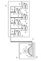
図3は、噴射ヘッド32にインクを供給するための構成を示した説明図である。本実施
例の噴射ヘッド32にインクを供給するための構成は、大まかには、インク供給部60と
、ヘッドユニット30の内部機構などから構成されている。尚、前述したように、本実施
例のヘッドユニット30には、異なる4色のインクを噴射するための複数の噴射ヘッド3
2が設けられているが(図2を参照)、ここでは、図が複雑となることを避けるために、
あるインク(例えばKインク)を噴射する噴射ヘッド32と、これらの噴射ヘッド32に
インクを供給するための構成のみが示されている。
B. Ink supply method of this embodiment:
FIG. 3 is an explanatory diagram showing a configuration for supplying ink to the
2 is provided (see FIG. 2), but here to avoid the complexity of the figure,
Only an
インク供給部60には、インクカートリッジ62や、インクカートリッジ62内のイン
クをヘッドユニット30に供給するための加圧ポンプ64などが設けられている。インク
カートリッジ62内には、インクが収容されたアルミ製のインクパック61が設けられて
おり、インクパック61は、インク供給流路65を介してヘッドユニット30に接続され
ている。また、加圧ポンプ64には圧迫部材63が設けられており、圧迫部材63は、加
圧ポンプ64で発生させた空気圧によって駆動されて、インクパック61を側面から圧迫
する。従って、加圧ポンプ64を作動させると、インクパック61が圧迫部材63によっ
て圧迫される圧力により、インクがインク供給流路65を通ってヘッドユニット30に供
給されるようになっている。
The
ヘッドユニット30に接続されたインク供給流路65は、ヘッドユニット30内で複数
の流路に分岐しており、分岐したインク供給流路65は、噴射ヘッド32へのインクの供
給圧力を調節する圧力調整弁90を介して噴射ヘッド32に接続されている。尚、本実施
例のラインプリンター1では、インク供給流路65が圧力調整弁90に接続される手前に
、圧力調整弁90を迂回するバイパス流路66が設けられており、バイパス流路66は、
開閉弁36を介して噴射ヘッド32に接続されている。こうしたバイパス流路66を設け
ておく理由については後に詳しく説明する。
The ink
It is connected to the
ここで、本実施例のラインプリンター1において、圧力調整弁90によって噴射ヘッド
32へのインクの供給圧力の調整を行うのは、次のような理由による。すなわち、本実施
例では、各インクカートリッジ62から噴射ヘッド32にインク供給流路65を介してイ
ンクを供給する構成をとっており、一本のインク供給流路65が分岐して複数の噴射ヘッ
ド32に接続している為、分岐した先のインク供給流路65内では、分岐する前のインク
供給流路65内と比べて、流路抵抗によってインクの圧力が大きく変化する。その結果、
噴射ヘッド32から正常にインクを吐出させるために必要なインクの供給圧力の下限値を
下回ってしまう場合があるので、インクカートリッジ62のインクパック61を加圧して
インクを供給する加圧供給システムを採用している。このようなインクの加圧供給システ
ムでは、加圧された液体が噴射ヘッド32に供給されるので、インクの供給圧力を維持す
ることが可能であるが、噴射ヘッド32に加圧力がそのまま伝わることでインクを正常に
吐出することができなくなったり、場合によっては噴射ノズルからインクが流れ出す不具
合が生ずる。そこで、こうした不具合を防止する目的で圧力調整弁90が設けられている
。
Here, in the line printer 1 of the present embodiment, the ink supply pressure to the
A pressure supply system that pressurizes the
また、噴射ヘッド32は、ヘッドユニット30の異なる位置に配置されているので(図
2を参照)、インク供給流路65が噴射ヘッド32に到達するまでの流路の長さは、噴射
ヘッド32ごとに異なっている場合がある。この場合、インクがインク供給流路65を流
れる際の圧力損失の違いによって、噴射ヘッド32へのインク供給圧力にバラつきが生ず
ることとなる。噴射ヘッド32は、液体を加圧することによって噴射しているので、噴射
ヘッド32へのインクの供給圧力を一定に保つことができなければ、噴射ヘッド32のイ
ンクの噴射量にバラつきが生じてしまい、その結果として、印刷画質の低下を招いてしま
う。このため、本実施例のラインプリンター1では、圧力調整弁90を用いることで、噴
射ヘッド32へのインクの供給圧力を一定に保っているのである。以下では、こうした圧
力調整弁90が、噴射ヘッド32へのインクの供給圧力を一定に保つための構造について
説明する。
Further, since the
図4は、圧力調整弁90の詳細な構造を示した説明図である。尚、図4には、圧力調整
弁90の中心を通る縦断面をとることによって、圧力調整弁90の内部構造が示されてい
る。
FIG. 4 is an explanatory view showing a detailed structure of the
本実施例の圧力調整弁90には、インクを溜めておく空間が2か所設けられている。す
なわち、圧力調整弁90の上側には、噴射ヘッド32に接続された圧力室91が設けられ
ており、弁の下側には、インクカートリッジ62に接続された前室92が設けられている
。圧力室91と前室92との間を隔てる隔壁には、細い通路が貫通しており、この通路に
は、通路とほぼ同じ径の通路軸93が通路内で摺動可能に設けられている。通路軸93の
側面には、2本の通路溝94が設けられており、通路溝94の一端は、圧力室91側に開
口するとともに、他端は前室92側に開口している。
The
通路軸93の圧力室91側の端部には、ベース部材95が固定されており、ベース部材
95は、通路軸93を取り巻くように設けられた支持バネ96によって、圧力室91の底
面側から一定の高さに持ち上げられている。また、ベース部材95は、圧力室91の一側
面(図4では上面側)を構成する薄いフィルム膜97のほぼ中央位置に接着されている。
A
また、通路軸93の前室92側の端部には、ゴム製の封止弁98が設けられている。封
止弁98は、前室92の底面側から封止バネ99によって上方に押し上げられており、通
常は、封止弁98の上方に設けられた突出部分が、前室92の上面に押し付けられること
で、前室92側から通路軸93の周囲を密閉するようになっている。
A
図5は、圧力調整弁90が噴射ヘッド32にインクを供給する圧力を調整する動作を示
した説明図である。前述したように、圧力調整弁90には、インク供給流路65を介して
インクカートリッジ62からインクが供給されている(図3を参照)。このとき、圧力調
整弁90の前室92には、加圧ポンプ64の押圧力によって、比較的高い圧力でインクが
供給されるようになっている。ここで、図4を用いて前述したように、通常は、前室92
に設けられた封止弁98によって、前室92側の通路軸93の周囲は密閉されているので
、図5(a)に示されるように、通路軸93に設けられた通路溝94の前室92側の開口
部分は、封止弁98によって前室92との接続を断たれた状態となっている。従って、こ
の状態では、前室92から通路溝94を介して圧力室91にインクが供給されることはな
い。
FIG. 5 is an explanatory diagram showing an operation in which the
Since the periphery of the
図5(a)に示す状態で、噴射ヘッド32からインクを噴射すると、噴射した分だけ噴
射ヘッド32内のインクの量が減少するが、すぐに噴射量に相当するインクが所定の圧力
によって圧力室91から供給される。また、こうして圧力室91から噴射ヘッド32にイ
ンクを供給すると、圧力室91内のインク量は徐々に減少していく。このとき、図5(b
)に示されるように、圧力室91内のインクの体積変化に応じて、圧力室91の上面を構
成するフィルム膜97が引き下げられることで、フィルム膜97が設けられたベース部材
95も支持バネ96の反発力に逆らって下方へ移動する。すると、ベース部材95に固定
された通路軸93も下方へと移動し、結果として、通路軸93の前室92側の端部によっ
て、封止弁98が、封止バネ99の反発力に逆らって下方へ押し下げられる。
When ink is ejected from the ejecting
), The
封止弁98が下方へ押し下げられると、前室92の上面に密着していた封止弁98の突
出部分が上面から離れるので、通路軸93に設けられた通路溝94の前室92側の開口部
分は前室92と接続可能な状態となる。その結果、図5(c)に示されるように、通路溝
94を介して、前室92から圧力室91へと加圧されたインクが供給される。
When the sealing
こうして圧力室91にインクが供給されると、圧力室91内のインク量が増加し、これ
に伴ってフィルム膜97とともにベース部材95が元の高さまで上昇する。従って、通路
軸93も上昇し、その結果として、図5(a)に示すように、再び封止弁98によって前
室92側の通路軸93の周囲は密閉されて、前室92から圧力室91へのインクの供給が
終了する。
When ink is supplied to the
以上のように、圧力調整弁90では、通常は封止弁98が閉じているが、圧力室91内
のインク量が所定量よりも少なくなることで圧力室91のインクの供給圧力が低下すると
、一時的に封止弁98が開く。これにより、前室92から加圧された少量のインクが供給
され、圧力室91のインクの供給圧力は回復する。その結果、圧力室91のインクの供給
圧力は、前室92よりも上流側の圧力よりも低い所定の圧力範囲に保たれるので、噴射ヘ
ッド32にインクを供給する圧力を一定に保つことが可能となっている。このような圧力
調整弁90を備えたラインプリンター1では、噴射ヘッド32へのインクの供給圧力が一
定に保たれることで、インクの噴射量のバラつきを抑えることが可能である。
As described above, in the
ここで、前述したように、本実施例のラインプリンター1では、噴射ヘッド32内でイ
ンクの性状が劣化した場合のメンテナンス動作として、加圧クリーニング(噴射ヘッド3
2内を加圧することにより、噴射ヘッド32内の劣化したインクを排出する動作)を採用
している。しかし、噴射ヘッド32の上流側には圧力調整弁90が設けられており、圧力
調整弁90では、上流から供給されたインクの圧力を所定の圧力範囲に減圧して噴射ヘッ
ド32に供給するため、(図4を参照)、圧力調整弁90を介しては、加圧したインクの
圧力を利用して噴射ヘッド32のインクを排出する加圧クリーニングを行うことはできな
い。そこで、本実施例のラインプリンター1では、以下のような方法によって加圧クリー
ニングを実行する。
Here, as described above, in the line printer 1 of the present embodiment, as a maintenance operation when the properties of the ink deteriorate in the
The operation of discharging the deteriorated ink in the
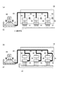
図6は、本実施例のラインプリンター1が加圧クリーニングを実行する方法を示した説
明図である。尚、図6(a)には、噴射ヘッド32からインクを噴射している際のヘッド
ユニット30の内部機構の様子が示されており、図6(b)には、加圧クリーニングを行
っている際のヘッドユニット30の内部機構の様子が示されている。
FIG. 6 is an explanatory diagram showing a method in which the line printer 1 of this embodiment executes pressure cleaning. 6A shows the internal mechanism of the
前述したように、本実施例のラインプリンター1では、ヘッドユニット30内のインク
供給流路65から、圧力調整弁90を迂回するバイパス流路66が設けられており、バイ
パス流路66は、開閉弁36を介して噴射ヘッド32に接続されている(図3を参照)。
また、バイパス流路66の開閉弁36は、噴射ヘッド32からインクを噴射している最中
を含め、通常は閉じた状態となっているため、加圧ポンプ64によってインクを加圧して
ヘッドユニット30に供給したとしても、加圧したインクはバイパス流路66の先には供
給されないようになっている。従って、図6(a)に太線で示されるように、圧力調整弁
90の上流までは加圧されたインクが供給される。このとき、前述したように、圧力調整
弁90によって噴射ヘッド32へのインクの供給圧力は所定範囲まで減圧されている。
As described above, in the line printer 1 of the present embodiment, the
The on-off
一方、噴射ヘッド32内でインクの性状が劣化した場合には、先ず、上述したバイパス
流路66の開閉弁36を開く。こうすると、圧力調整弁90を迂回して、直接インクを噴
射ヘッド32に供給可能な流路が確保される。続いて、加圧ポンプ64を駆動して、加圧
したインクをヘッドユニット30に供給する。尚、このときインクを加圧する圧力は、噴
射ヘッド32からインクを噴射する際の圧力と同じ圧力(20kpa程度)であってもよ
いし、インクを噴射する際よりも高めの圧力(30kpa〜40kpa)であってもよい
。また、加圧ポンプ64を駆動した状態で、バイパス流路66の開閉弁36を開いてもよ
いし、加圧ポンプ64の駆動開始と開閉弁36の開放とを同時に行うこととしてもよい。
On the other hand, when the ink properties deteriorate in the
開閉弁36を開いた状態で加圧されたインクがヘッドユニット30に供給されると、図
6(b)に太線で示されるように、バイパス流路66を介して、インクが噴射ヘッド32
に流入する。こうすると、加圧したインクの高い供給圧力を維持したまま、噴射ヘッド3
2にインクが供給されるので、噴射ヘッド32内の圧力が高められる。その結果、噴射ヘ
ッド32内で性状が劣化したインクが噴射ノズルから排出する加圧クリーニングを実行す
ることが可能となる。そして、性状の劣化したインクを排出したら、バイパス流路66の
開閉弁36を閉じることで、圧力調整弁90を迂回して噴射ヘッド32にインクを供給す
る流路を遮断するとともに、加圧ポンプ64を停止することで、加圧クリーニングを終了
する。
When the pressurized ink is supplied to the
Flow into. In this way, the
2 is supplied with ink, the pressure in the
以上のように、圧力調整弁90を迂回して、直接インクを噴射ヘッド32に供給可能な
バイパス流路66を設けておけば、噴射ヘッド32の上流側に圧力調整弁90が設けられ
ていたとしても、必要に応じて、加圧したインクの圧力を噴射ヘッド32に伝えることが
できる。従って、加圧したインクの圧力を減圧して用いることで噴射ヘッド32へのイン
クの供給圧力を一定に保つという、圧力調整弁90の本来の機能は維持したまま、加圧ク
リーニングを実行することが可能となる。
As described above, if the
ここで、噴射ヘッド32に圧力調整弁90を設けたまま、性状が劣化したインクを噴射
ヘッド32外に排出可能とする方法としては、上述した加圧クリーニングに替えて、イン
クを噴射ノズルから吸引するメンテナンス動作である吸引クリーニングを採用することも
考えられる。しかし、吸引クリーニングを行うに際しては、キャップ40を噴射ヘッド3
2に押し当てることでキャップ40と噴射ヘッド32との間に閉空間を形成しなければな
らず、キャップ40を噴射ヘッド32のノズル面に当接させる必要がある。特に、複数の
噴射ヘッド32を搭載したラインプリンター1では、吸引クリーニングに備えて噴射ヘッ
ド32毎にキャップ40が設けられることもあり、これら複数のキャップ40をノズル面
の正確な位置に当接させることは、必ずしも容易なことではない。
Here, as a method for allowing ink whose properties have deteriorated to be discharged out of the
2, a closed space must be formed between the
これに対して、本実施例のように、圧力調整弁90を迂回するバイパス流路66を設け
ることで、加圧クリーニングを採用可能とすれば、噴射ヘッド32から排出されたインク
をキャップ40で受けるだけでよい。従って、キャップ40で噴射ヘッド32のノズル面
を覆わなくてもよいので、上述した吸引クリーニングのように、キャップ40をノズル面
に当接させる動作を省略することができる。
On the other hand, if the pressure cleaning can be adopted by providing the
また、本実施例の加圧クリーニングでは、加圧ポンプ64がインクを供給する圧力を、
噴射ヘッド32内を加圧するための圧力として利用している。従って、加圧クリーニング
を実行するための専用のポンプを設ける必要がない。また加圧クリーニングを行う際には
、インクを噴射する際よりも高い圧力によってインクを加圧して供給することで、加圧ク
リーニングによるインクの排出能力を高めることも可能である。
In the pressure cleaning of this embodiment, the pressure at which the
This is used as a pressure for pressurizing the inside of the
C.変形例 :
前述した実施例のラインプリンター1では、複数の噴射ヘッド32の各々に対して、噴
射ヘッド32へのインクの供給圧力を調整する圧力調整弁90を設けるものと説明した。
しかし、圧力調整弁90は、次のようにして設けることとしてもよい。
C. Modified example:
In the line printer 1 of the above-described embodiment, it has been described that the
However, the
図7は、変形例のラインプリンター1が噴射ヘッド32にインクを供給するための構成
を示した説明図である。図示されているように、変形例のラインプリンター1では、圧力
調整弁90は1つだけ設けられており、インクカートリッジ62からのインクを導くイン
ク供給流路65は、1つの圧力調整弁90を介して全ての噴射ヘッド32に接続されてい
る。また、圧力調整弁90の上流側からは、圧力調整弁90を迂回するバイパス流路66
が設けられており、バイパス流路66の開閉弁36を閉じた状態では、圧力調整弁90に
よって噴射ヘッド32へのインクの供給圧力を一定に保ち、開閉弁36を開いた状態では
、噴射ヘッド32に加圧したインクを導いて加圧クリーニングを行うことができるように
なっている。また、各噴射ヘッド32の直ぐ上流の位置には、インク供給流路65の開閉
を切替え可能な切替弁38が設けられている。このため、インクを排出したい噴射ヘッド
32に対応する切替弁38を開き、その他の切替弁38は閉じた状態で加圧クリーニング
を実行することで、選択的に加圧クリーニングを実行することが可能になっている。
FIG. 7 is an explanatory diagram showing a configuration for supplying ink to the
When the on-off
このような変形例のラインプリンター1では、選択的に加圧クリーニングを実行するた
めの切替弁38を設ける必要が生ずる一方で、圧力調整弁90の設置数を減らすことがで
きる。ここで、前述したように、圧力調整弁90は、噴射ヘッド32に供給するインクの
圧力を一定に保つために複雑な構造を有しており(図4を参照)、こうした圧力調整弁9
0と比べれば、切替弁38は、流路の開閉だけを行うための単純な構造のものをとなって
いる。従って、圧力調整弁90の設置数を減らすことにより、ラインプリンター1が噴射
ヘッド32にインクを供給するための構成を簡単にすることができる。
In the line printer 1 of such a modification, it is necessary to provide the switching
Compared with 0, the switching
以上、本願発明の実施例について説明したが、本発明は上記に限られるものではなく、
その要旨を逸脱しない範囲において種々の態様で実施することが可能である。
As mentioned above, although the Example of this invention was described, this invention is not limited above,
The present invention can be implemented in various modes without departing from the gist thereof.
1…ラインプリンター、 30…ヘッドユニット、 32…噴射ヘッド、
36…開閉弁、 40…キャップ、 50…吸引ポンプ、
60…インク供給部、 62…インクカートリッジ、 64…加圧ポンプ、
65…インク供給流路、 66…バイパス流路、 90…圧力調整弁、
91…圧力室、 92…前室、 93…通路軸、
94…通路溝、 97…フィルム膜、 98…封止弁
1 ... Line printer, 30 ... Head unit, 32 ... Ejecting head,
36 ... Open / close valve, 40 ... Cap, 50 ... Suction pump,
60 ... Ink supply section, 62 ... Ink cartridge, 64 ... Pressure pump,
65 ... Ink supply channel, 66 ... Bypass channel, 90 ... Pressure regulating valve,
91 ... Pressure chamber, 92 ... Front chamber, 93 ... Passage shaft,
94 ... passage groove, 97 ... film membrane, 98 ... sealing valve
Claims (2)
前記噴射ノズルから噴射する液体を、液体流路を介して前記噴射ヘッドに向けて圧送する液体供給部と、
前記液体供給部と前記噴射ヘッドとの間の前記液体流路に設けられた圧力調整手段であって、該圧力調整手段と前記噴射ヘッドとの間の液体の圧力が所定の圧力範囲になったときのみに開弁する圧力調整弁を有する圧力調整手段と、
前記圧力調整弁の上流側と下流側とを接続するバイパス通路を開いて、前記液体供給部から圧送された液体を前記噴射ヘッドに導くことにより、該噴射ヘッド内の液体を前記噴射ノズルから排出させるクリーニング動作を行う加圧クリーニング手段と
を備える液体噴射装置。 A liquid ejecting apparatus that ejects liquid from an ejection nozzle provided in an ejection head,
A liquid supply unit that pumps the liquid ejected from the ejection nozzle toward the ejection head via a liquid flow path ;
Pressure adjusting means provided in the liquid flow path between the liquid supply unit and the ejection head, and the pressure of the liquid between the pressure adjustment means and the ejection head is within a predetermined pressure range. Pressure regulating means having a pressure regulating valve that opens only when,
By opening a bypass passage connecting the upstream side and the downstream side of the pressure regulating valve and guiding the liquid pressure-fed from the liquid supply unit to the ejection head, the liquid in the ejection head is discharged from the ejection nozzle. And a pressure cleaning means for performing a cleaning operation.
前記液体供給部は、前記クリーニング動作時は、該クリーニング動作を行っていない状態よりも高い圧力で、液体を圧送する液体噴射装置。 The liquid ejecting apparatus according to claim 1,
The liquid supply portion during the cleaning operation, at a pressure higher than the state not subjected to the cleaning operation, the liquid ejecting apparatus for pumping liquids.
Priority Applications (1)
| Application Number | Priority Date | Filing Date | Title |
|---|---|---|---|
| JP2010028624A JP5413229B2 (en) | 2010-02-12 | 2010-02-12 | Liquid ejector |
Applications Claiming Priority (1)
| Application Number | Priority Date | Filing Date | Title |
|---|---|---|---|
| JP2010028624A JP5413229B2 (en) | 2010-02-12 | 2010-02-12 | Liquid ejector |
Related Child Applications (1)
| Application Number | Title | Priority Date | Filing Date |
|---|---|---|---|
| JP2013228064A Division JP5679034B2 (en) | 2013-11-01 | 2013-11-01 | Liquid ejector |
Publications (3)
| Publication Number | Publication Date |
|---|---|
| JP2011161844A JP2011161844A (en) | 2011-08-25 |
| JP2011161844A5 JP2011161844A5 (en) | 2013-02-21 |
| JP5413229B2 true JP5413229B2 (en) | 2014-02-12 |
Family
ID=44593081
Family Applications (1)
| Application Number | Title | Priority Date | Filing Date |
|---|---|---|---|
| JP2010028624A Active JP5413229B2 (en) | 2010-02-12 | 2010-02-12 | Liquid ejector |
Country Status (1)
| Country | Link |
|---|---|
| JP (1) | JP5413229B2 (en) |
Families Citing this family (7)
| Publication number | Priority date | Publication date | Assignee | Title |
|---|---|---|---|---|
| JP2014030948A (en) * | 2012-08-02 | 2014-02-20 | Mimaki Engineering Co Ltd | Ink jet recorder, liquid supply device, and method for cleaning recording head |
| JP6307912B2 (en) * | 2014-02-07 | 2018-04-11 | セイコーエプソン株式会社 | Liquid ejector |
| JP6256692B2 (en) | 2014-03-06 | 2018-01-10 | セイコーエプソン株式会社 | Liquid ejecting apparatus and control method thereof |
| US9358802B2 (en) | 2014-03-28 | 2016-06-07 | Seiko Epson Corporation | Liquid ejecting head, liquid ejecting apparatus, flow passage member, and method of controlling liquid ejecting head |
| JP6690380B2 (en) * | 2016-04-18 | 2020-04-28 | コニカミノルタ株式会社 | Droplet discharging apparatus and method of controlling droplet discharging apparatus |
| JP6501012B2 (en) * | 2018-03-05 | 2019-04-17 | セイコーエプソン株式会社 | Liquid injection apparatus and maintenance method for liquid injection apparatus |
| JP7031422B2 (en) * | 2018-03-26 | 2022-03-08 | 京セラドキュメントソリューションズ株式会社 | Liquid sprayer |
Family Cites Families (6)
| Publication number | Priority date | Publication date | Assignee | Title |
|---|---|---|---|---|
| JP3161095B2 (en) * | 1992-11-06 | 2001-04-25 | セイコーエプソン株式会社 | Ink jet recording device |
| JP2000085141A (en) * | 1998-09-09 | 2000-03-28 | Canon Inc | Ink jet recorder and ink supplying method |
| JP3788065B2 (en) * | 1998-09-29 | 2006-06-21 | ブラザー工業株式会社 | Inkjet recording device |
| JP2001232813A (en) * | 2000-02-25 | 2001-08-28 | Hitachi Koki Co Ltd | Ink jet recorder |
| JP4256184B2 (en) * | 2003-03-19 | 2009-04-22 | エスアイアイ・プリンテック株式会社 | Liquid jet recording apparatus and ink filling method |
| JP2004351845A (en) * | 2003-05-30 | 2004-12-16 | Sii Printek Inc | Droplet jetting type recording device and method for operating it |
-
2010
- 2010-02-12 JP JP2010028624A patent/JP5413229B2/en active Active
Also Published As
| Publication number | Publication date |
|---|---|
| JP2011161844A (en) | 2011-08-25 |
Similar Documents
| Publication | Publication Date | Title |
|---|---|---|
| JP5413229B2 (en) | Liquid ejector | |
| JP5488052B2 (en) | Liquid ejector | |
| KR101430934B1 (en) | Ink-jet image forming apparatus and method of controlling ink flow | |
| JP6256692B2 (en) | Liquid ejecting apparatus and control method thereof | |
| US8622533B2 (en) | Inkjet recording apparatus and method for removing air bubbles in inkjet recording apparatus | |
| US20120050421A1 (en) | Inkjet printing device and method for replacing a print head | |
| US10464320B2 (en) | Liquid ejecting head, liquid ejecting apparatus, and control method for liquid ejecting apparatus | |
| JP5434673B2 (en) | Liquid ejector | |
| JP5679034B2 (en) | Liquid ejector | |
| US9079416B2 (en) | Liquid ejection apparatus | |
| JP2009126098A (en) | Liquid feeding device and its controlling method | |
| JP5983827B2 (en) | Liquid ejector | |
| JP2007118540A (en) | Liquid jet apparatus and liquid supply unit | |
| EP3566875B1 (en) | Liquid ejecting apparatus, liquid filling method, and air bubble discharging method | |
| JP5493796B2 (en) | Liquid ejector | |
| JP6488897B2 (en) | Liquid ejecting apparatus and control method thereof | |
| US9242469B2 (en) | Liquid ejecting apparatus and maintenance method | |
| JP5597324B2 (en) | Printer device | |
| JP2018094868A (en) | Inkjet printer and method for cleaning ink head in inkjet printer | |
| JP5516019B2 (en) | Liquid ejector | |
| JP2011167959A (en) | Liquid injector | |
| JP5212192B2 (en) | Image forming apparatus | |
| JP2015112847A (en) | Liquid supply device and image formation device including the same | |
| JP3879525B2 (en) | Inkjet printer head and inkjet printer | |
| JP2018099829A (en) | Head cleaning mechanism and inkjet recording device including the same |
Legal Events
| Date | Code | Title | Description |
|---|---|---|---|
| A521 | Written amendment |
Free format text: JAPANESE INTERMEDIATE CODE: A523 Effective date: 20130108 |
|
| A621 | Written request for application examination |
Free format text: JAPANESE INTERMEDIATE CODE: A621 Effective date: 20130108 |
|
| TRDD | Decision of grant or rejection written | ||
| A01 | Written decision to grant a patent or to grant a registration (utility model) |
Free format text: JAPANESE INTERMEDIATE CODE: A01 Effective date: 20131015 |
|
| A61 | First payment of annual fees (during grant procedure) |
Free format text: JAPANESE INTERMEDIATE CODE: A61 Effective date: 20131028 |
|
| R150 | Certificate of patent or registration of utility model |
Ref document number: 5413229 Country of ref document: JP Free format text: JAPANESE INTERMEDIATE CODE: R150 |
|
| S531 | Written request for registration of change of domicile |
Free format text: JAPANESE INTERMEDIATE CODE: R313531 |
|
| R350 | Written notification of registration of transfer |
Free format text: JAPANESE INTERMEDIATE CODE: R350 |