JP5412766B2 - Electronic musical instruments and programs - Google Patents
Electronic musical instruments and programs Download PDFInfo
- Publication number
- JP5412766B2 JP5412766B2 JP2008223023A JP2008223023A JP5412766B2 JP 5412766 B2 JP5412766 B2 JP 5412766B2 JP 2008223023 A JP2008223023 A JP 2008223023A JP 2008223023 A JP2008223023 A JP 2008223023A JP 5412766 B2 JP5412766 B2 JP 5412766B2
- Authority
- JP
- Japan
- Prior art keywords
- key
- signal data
- waveform data
- tone signal
- musical
- Prior art date
- Legal status (The legal status is an assumption and is not a legal conclusion. Google has not performed a legal analysis and makes no representation as to the accuracy of the status listed.)
- Active
Links
Images


Description
本発明は、電子楽器及びプログラムに関する。 The present invention relates to an electronic musical instrument and a program.
通常の生楽器では、一つの音色の楽音でしか演奏をすることができないが、電子楽器においては、様々な音がユーザの好みで選択でき、その楽器の演奏者になったような気持ちで演奏を楽しむことが可能である。しかしながらこの電子楽器が鍵盤楽器であるなら、鍵盤をオン・オフ操作するだけのきわめて単純な操作しか行えない。もちろん、鍵盤の押鍵速度をコントロールすることにより、発生する楽音の音色、音量、音高等を制御することは可能であるが、これだけでは、例えばバイオリンや管楽器などの非鍵盤楽器を演奏したときの繊細な音楽表現を付加することはできない。 A normal live musical instrument can only be played with a single tone, but an electronic musical instrument can be selected with various sounds according to the user's preference. It is possible to enjoy. However, if this electronic musical instrument is a keyboard instrument, it is possible to perform an extremely simple operation by simply turning the keyboard on and off. Of course, it is possible to control the tone, volume, pitch, etc. of the generated musical tone by controlling the key-pressing speed of the keyboard, but with this alone, for example, when playing non-keyboard instruments such as violins and wind instruments It is not possible to add delicate musical expressions.
これを解決するためには、例えば鍵盤楽器においては、押鍵により発生した楽音にバイオリンや管楽器等と同じような変化を与えるために種々の工夫がなされてきた。たとえば、鍵盤楽器の左端に回転可能なホイールを設け、あいている手を用いてホイールを操作し、その回転角によって発生した楽音の音高を変化させ、或いは、そのビブラートを制御することが一般に行われている。 In order to solve this, for example, in a keyboard musical instrument, various ideas have been made in order to give a change similar to that of a violin, a wind musical instrument or the like to a musical sound generated by pressing a key. For example, it is common to provide a rotatable wheel at the left end of a keyboard instrument, operate the wheel with the open hand, change the pitch of the musical sound generated by the rotation angle, or control the vibrato Has been done.
また、特許文献1には、上述したようなピッチ変更(ピッチベンド)のためにホイールを用いずに、所定の複数の鍵に予めピッチベンド操作子としての機能を与え、ピッチベンド操作子として機能する鍵の操作によって発音中の楽音のピッチ変更を実現するような鍵盤楽器が提案されている。
Further, in
また、特許文献2には、タッピングハーモニクス奏法をシミュレートできる電子弦楽器が提案されている。特許文献2に開示された電子弦楽器においては、あるフレット位置で弦が操作されて対応する楽音が発音されている状態で、一定の音高差のフレット位置が押された場合に、発音中の楽音がハーモニクス音に変化する。
たとえば、特許文献1に開示された技術では、ベンドアップ用としての複数の鍵、ベンドダウン用の複数の鍵、および、その中央に位置するピッチを元に戻す操作用の鍵が、ピッチベンド用に使用されている。したがって、このピッチベンド用の鍵は、発音のために鍵を押鍵する手(たとえば右手)では操作できず、もう一方の手(たとえば左手)で操作しなければならない。このため、一方の手に意識を集中させることができず、繊細な音楽表現を付加することは困難である。
For example, in the technique disclosed in
また、特許文献2に開示された技術においては、発音中の楽音(通常の楽音)が別の音色に切り替わるだけであるから、その表現自体は単調なものである。このため、演奏に織り込みたい複雑な表現を行うことができなかった。
Further, in the technique disclosed in
さらに、より繊細な音楽表現を付加するため考慮しなければならない課題がある。それは、非鍵盤楽器を演奏したときに、その非鍵盤楽器特有の演奏操作に伴って生じる機械的なノイズ音である。例えばバイオリンであれば弓と弦がこすれるときに発生するこすれ音、あるいは管楽器であればマウスピースからもれる空気プレッシャー音、というような、弓又は弦のびびりから発生するノイズがこれに相当する。 Furthermore, there are issues that must be considered in order to add more delicate musical expressions. It is a mechanical noise sound that is generated by a performance operation unique to a non-keyboard instrument when the non-keyboard instrument is played. For example, a noise generated from chatter of a bow or a string such as a rubbing sound generated when a bow and a string are rubbed with a violin or an air pressure sound leaking from a mouthpiece with a wind instrument corresponds to this.
この演奏操作音は、演奏者の演奏のしかたに大きく依存しており、通常の非鍵盤楽器ではこの演奏操作音が発生する楽音に混合されることにより、演奏者の意図する音楽表現が、発生する楽音に付加されるといえる。 This performance operation sound greatly depends on the performance method of the performer, and the music expression intended by the performer is generated by mixing it with the musical sound generated by this performance operation sound with a normal non-keyboard instrument. It can be said that it is added to the music to be played.
上記特許文献1、2では、このような点については何ら考慮がなされていない。
In the
本発明は、簡単でわかりやすい鍵盤楽器の演奏操作により、非鍵盤楽器おいてのみ可能な複雑な音楽表現を発生する楽音に対して付加できる電子楽器およびプログラムを提供することを目的とする。 An object of the present invention is to provide an electronic musical instrument and a program that can be added to a musical sound that generates a complicated musical expression that can be performed only with a non-keyboard instrument by performing a simple and easy-to-understand operation of the keyboard instrument.
本発明は上記目的を達成するために、
複数の鍵を有する鍵盤と、
前記鍵盤の各鍵に対して、当該鍵の押下にともなって順次オンする複数のスイッチを設けるとともに、前記複数のスイッチ夫々のオン時刻の時間差に基づいて押鍵速度を検出する押鍵速度検出手段と、
音色毎に、当該音色の楽音を表わす第1の波形データ、及び前記第1の波形データによって表される楽音に関連付けられた効果音を表わす第2の波形データを記憶する波形データ記憶手段と、
前記鍵盤のいずれの鍵も押鍵されていない状態において第1の鍵が押鍵された場合に、当該押鍵された鍵に割当てられた音高で前記波形データ記憶手段に記憶された指定された音色の第1の波形データを読み出して第1のエンベロープを付加することにより、第1の楽音信号データを生成する第1の楽音信号データ生成手段と、
前記第1の鍵が押鍵された時点から所定の時間内でかつ、当該押鍵されている第1の鍵を基準に前記鍵盤上の所定の範囲内に位置する第2の鍵が押鍵された場合に、前記第1の鍵に割当てられた音高に関連する音高で前記波形データ記憶手段から前記第1の波形データに対応する第2の波形データを読み出して第2のエンベロープを付加することにより、第2の楽音信号データを生成する第2の楽音信号データ生成手段と、
前記押鍵速度検出手段により、前記第1の鍵の押鍵に伴って検出された第1の押鍵速度と前記第2の鍵の押鍵に伴って検出された第2の押鍵速度との速度差を算出し、当該算出された速度差に基づいて前記第2の波形データに付加される第2のエンベロープを制御するエンベロープ制御手段と、
を有することを特徴とする。
In order to achieve the above object, the present invention
A keyboard having a plurality of keys;
For each key of the keyboard, a plurality of switches that are sequentially turned on as the keys are pressed are provided, and a key pressing speed detecting unit that detects a key pressing speed based on a time difference between the ON times of the plurality of switches. When,
Waveform data storage means for storing, for each tone color, first waveform data representing a tone of the tone and second waveform data representing a sound effect associated with the tone represented by the first waveform data ;
When the first key is pressed in a state where none of the keys on the keyboard is pressed, the designated pitch stored in the waveform data storage means is assigned to the pitch assigned to the pressed key. First musical tone signal data generating means for generating first musical tone signal data by reading out the first waveform data of the selected timbre and adding a first envelope;
The second key located within a predetermined range on the keyboard within a predetermined time from the time when the first key is pressed and within the predetermined range on the basis of the pressed first key The second waveform data corresponding to the first waveform data is read from the waveform data storage means at the pitch associated with the pitch assigned to the first key, and the second envelope is obtained. A second musical tone signal data generating means for generating second musical tone signal data by adding,
A first key pressing speed detected with the key pressing of the first key and a second key pressing speed detected with the key pressing of the second key by the key pressing speed detecting means; An envelope control means for controlling a second envelope added to the second waveform data based on the calculated speed difference;
It is characterized by having.
請求項2での発明では、
前記エンベロープ制御手段は、前記第2の鍵の押鍵に伴って検出された押鍵速度が、前記第1の鍵に伴って検出された押鍵速度より大きくなるにしたがって、前記第2の波形データに付与される第2のエンベロープのアタックレートが大きくなるように制御することを特徴とする。
In the invention of
The envelope control means has the second waveform as the key pressing speed detected with the pressing of the second key becomes larger than the key pressing speed detected with the first key. Control is performed such that the attack rate of the second envelope added to the data is increased .
請求項3での発明では、
前記エンベロープ制御手段は、前記第1の鍵の押鍵タイミングと前記第2の鍵の押鍵タイミングとのタイミング差に基づいて、前記速度差を補正することを特徴とする。
In the invention of
The envelope control unit corrects the speed difference based on a timing difference between a key pressing timing of the first key and a key pressing timing of the second key .
請求項4での発明では、
前記電子楽器はさらに、前記第1の鍵が離鍵されたときに、前記第1及び第2の楽音信号データにより発音された楽音の消音を指示する消音指示手段を有することを特徴とする。
In the invention of claim 4,
The electronic musical instrument further includes a mute instruction means for instructing mute of a musical sound produced by the first and second musical sound signal data when the first key is released .
請求項5での発明では、
前記電子楽器はさらに、前記第1の楽音信号データが生成されている状態でかつ前記第2の楽音信号データが生成を開始した時点から、所定の第2の時間内でかつ、当該押鍵されている第1の鍵を基準に前記鍵盤上の所定の範囲内に位置する第3の鍵が押鍵された場合に、前記第1の楽音信号データ及び第2の楽音信号データを制御する制御手段を有することを特徴とする。
In the invention of claim 5,
The electronic musical instrument is further pressed within a predetermined second time from when the first musical tone signal data is generated and the second musical tone signal data is generated. Control for controlling the first musical tone signal data and the second musical tone signal data when a third key located within a predetermined range on the keyboard is depressed with the first key as a reference It has the means .
請求項6での発明では、
前記電子楽器はさらに、前記第1及び第2の楽音信号データに対してビブラートを付与するビブラート付与手段を有し、
前記制御手段が、前記第3の鍵の押鍵タイミングと前記第2の鍵の押鍵タイミングとの間の第1のタイミング差、及び前記第2の鍵の押鍵タイミングと前記第1の鍵の押鍵タイミングとの間の第2のタイミング差を算出し、当該第1及び第2のタイミング差の差分に基づいて、前記ビブラート付与手段にて前記第1及び第2の楽音信号データに付与されるビブラートを制御するビブラート制御手段を有することを特徴とする。
In the invention of claim 6,
The electronic musical instrument further includes vibrato imparting means for imparting vibrato to the first and second musical tone signal data,
The control means includes a first timing difference between a key pressing timing of the third key and a key pressing timing of the second key, and a key pressing timing of the second key and the first key. And calculating the second timing difference between the first and second musical tone signal data based on the difference between the first timing difference and the second timing difference. It has a vibrato control means for controlling the vibrato to be performed.
請求項7での発明では、
前記制御手段はさらに、前記押鍵速度検出手段により前記第2及び第3の鍵夫々の押鍵に伴って検出された押鍵速度の差分を算出するとともに、前記差分に基づいて前記第1の楽音信号データおよび第2の楽音信号データの音量レベルを制御することを特徴とする。
In the invention of claim 7,
The control means further calculates a difference between the key pressing speeds detected by the key pressing speed detecting means with the key pressing of the second and third keys, and based on the difference, It is characterized by controlling the volume levels of the musical tone signal data and the second musical tone signal data .
請求項8での発明では、
複数の鍵を有する鍵盤と、前記鍵盤の各鍵に対して、当該鍵の押下にともなって順次オンする複数のスイッチを設けるとともに、前記複数のスイッチ夫々のオン時刻の時間差に基づいて押鍵速度を検出する押鍵速度検出手段と、音色毎に、当該音色の楽音を表わす第1の波形データ、及び前記第1の波形データによって表される楽音に関連付けられた効果音を表わす第2の波形データを記憶する波形データ記憶手段と、を有する電子楽器に適用されるコンピュータに、
前記鍵盤のいずれの鍵も押鍵されていない状態において第1の鍵が押鍵された場合に、当該押鍵された鍵に割当てられた音高で前記波形データ記憶手段に記憶された指定された音色の第1の波形データを読み出して第1のエンベロープを付加することにより、第1の楽音信号データを生成する第1の楽音信号データ生成ステップと、
前記第1の鍵が押鍵された時点から所定の時間内でかつ、当該押鍵されている第1の鍵を基準に前記鍵盤上の所定の範囲内に位置する第2の鍵が押鍵された場合に、前記第1の鍵に割当てられた音高に関連する音高で前記波形データ記憶手段から前記第1の波形データに対応する第2の波形データを読み出して第2のエンベロープを付加することにより、第2の楽音信号データを生成する第2の楽音信号データ生成ステップと、
前記押鍵速度検出手段により、前記第1の鍵の押鍵に伴って検出された第1の押鍵速度と前記第2の鍵の押鍵に伴って検出された第2の押鍵速度との速度差を算出し、当該算出された速度差に基づいて前記第2の波形データに付加される第2のエンベロープを制御するエンベロープ制御ステップと、
を実行させることを特徴とする。
In the invention of claim 8,
A keyboard having a plurality of keys, and a plurality of switches that are sequentially turned on as each key of the keyboard is pressed, and a key pressing speed based on a time difference between each of the plurality of switches. And a second waveform representing a sound effect associated with the musical tone represented by the first waveform data, and a first waveform data representing the musical tone of the timbre, and a second waveform representing a sound effect associated with the musical tone represented by the first waveform data. A computer applied to an electronic musical instrument having waveform data storage means for storing data;
When the first key is pressed in a state where none of the keys on the keyboard is pressed, the designated pitch stored in the waveform data storage means is assigned to the pitch assigned to the pressed key. A first musical tone signal data generating step of generating first musical tone signal data by reading out the first waveform data of the selected timbre and adding a first envelope;
The second key located within a predetermined range on the keyboard within a predetermined time from the time when the first key is pressed and within the predetermined range on the basis of the pressed first key The second waveform data corresponding to the first waveform data is read from the waveform data storage means at the pitch associated with the pitch assigned to the first key, and the second envelope is obtained. A second musical sound signal data generating step for generating second musical sound signal data by adding,
A first key pressing speed detected with the key pressing of the first key and a second key pressing speed detected with the key pressing of the second key by the key pressing speed detecting means; An envelope control step of controlling a second envelope added to the second waveform data based on the calculated speed difference;
Is executed.
本発明によれば、簡単でわかりやすい演奏操作により、発音中の楽音に複雑かつ繊細な演奏表現を付加することが可能となる。 According to the present invention, it is possible to add a complicated and delicate performance expression to a musical sound being generated by a simple and easy-to-understand performance operation.
以下、添付図面を参照して、本発明の実施の形態について説明する。図1は、本発明の第1の実施の形態にかかる電子楽器の構成を示すブロックダイヤグラムである。図1に示すように、本実施の形態にかかる電子楽器10は、CPU11、ROM12、RAM13、サウンドシステム14、表示部15、鍵盤17および操作部18を備える。
Embodiments of the present invention will be described below with reference to the accompanying drawings. FIG. 1 is a block diagram showing the configuration of the electronic musical instrument according to the first embodiment of the present invention. As shown in FIG. 1, the electronic
CPU11は、電子楽器10全体の制御、鍵盤17の鍵のオン・オフや操作部18を構成するスイッチ(図示せず)の操作の検出、鍵盤17やスイッチの操作にしたがったサウンドシステム14の制御を行う。特に、本実施の形態においてCPU11は、鍵盤17の鍵のオン中に、所定の他の鍵がオンされた場合に、新たな楽音信号データ生成のための制御情報を生成する。
The
ROM12は、鍵盤17を構成する鍵、操作部18を構成するスイッチのオンおよびオフの検出、鍵盤17の鍵のオンに基づく楽音信号処理、鍵のオン中に所定の他の鍵がオンされたときの新たな楽音信号生成処理などの処理プログラムを格納する。RAM13は、ROM12から読み出されたプログラムや、処理の過程で生じたデータを記憶する。
The
また、ROM12は、ピアノ、ギター、バスドラム、スネアドラム、シンバルなどの楽音を生成するための波形データを記憶するデータエリアを備えている。この波形データは外部操作によって適宜選択指定されるようになっている。なお、後述するように、本実施の形態においては、音色ごとに、その音色の楽音を表わす第1の波形データと、この音色の楽音を生成する際の演奏操作に伴って生じる演奏操作音を表わす第2の波形データである効果用波形データと、を有している。
The
演奏操作音とは、例えばバイオリンであれば弓と弦がこすれるときに発生するこすれ音、また管楽器であればマウスピースからもれる空気プレッシャー音というような、演奏操作子又は弦のびびりから発生する機械ノイズを表わしたものである。 For example, a performance sound is generated from a performance operator or chatter of a string such as a rubbing sound generated when the bow and string are rubbed with a violin, or an air pressure sound leaking from a mouthpiece with a wind instrument. It represents mechanical noise.
サウンドシステム14は、音源部21、オーディオ回路22およびスピーカ23を有する。音源部21は、たとえば、押鍵された鍵の音高情報、音色情報、波形データの選択情報、ベロシティ情報を含む制御情報をCPU11から受信すると、ROM12のデータエリアから、音色情報および波形データの選択情報にしたがった波形データを読み出して、音高情報に示す音高およびベロシティ情報、音色に対応したエンベロープ情報に基づいた楽音信号データを生成して出力する。オーディオ回路22は、楽音信号データをD/A変換して増幅する。これによりスピーカ23から音響信号が出力される。
The
図2は、本実施の形態にかかる電子楽器10にて実行される処理を示すフローチャートである。まず、電子楽器10のCPU11は、たとえば、RAM13に一時的に記憶された押鍵情報(鍵のオン時刻やオフ時刻)、発音情報などを制御情報のクリアを含むイニシャライズ処理を行う(ステップ201)。イニシャライズ処理(ステップ201)が終了すると、CPU11は、操作部18のスイッチの操作を検出し、検出された操作にしたがった処理を実行するスイッチ処理を実行する(ステップ202)。スイッチ処理においては、音色指定スイッチ(図示せず)の切り替えなどが検出される。
FIG. 2 is a flowchart showing processing executed by the electronic
また、本実施の形態においては、通常モードあるいはリッチモードの何れかで動作する。通常モードにおいては、鍵がオンされたときに、当該押鍵された鍵に対応する音高の第1の楽音信号データを生成するだけであるが、リッチモードの場合はこの第1の楽音信号データに加えて、鍵がオン中に他の所定の鍵がオンされたときに、第2の楽音信号データを生成する。 In the present embodiment, the operation is performed in either the normal mode or the rich mode. In the normal mode, when the key is turned on, only the first musical tone signal data having the pitch corresponding to the depressed key is generated. In the rich mode, the first musical tone signal is generated. In addition to the data, second tone signal data is generated when another predetermined key is turned on while the key is on.
このリッチモードで生成される第2の楽音信号データは、実際の生楽器で演奏者の表現によって引き出される演奏ノイズや演奏操作音を構成する。なお、本実施の形態において、「ベロシティ」とは、いわゆるMIDI規格に規定されるベロシティを意味し、楽音の強弱を示す。本明細書においては、速度(押鍵速度)は、そのまま「押鍵速度」と表現する。 The second musical tone signal data generated in the rich mode constitutes performance noise and performance operation sound that are derived from the expression of the performer with an actual live musical instrument. In the present embodiment, “velocity” means a velocity defined in a so-called MIDI standard and indicates the strength of a musical sound. In this specification, the speed (key pressing speed) is expressed as “key pressing speed” as it is.
スイッチ処理(ステップ202)で検出されたスイッチの状態にしたがって、音色情報や演奏モードを示す情報はRAM13に格納される。次いで、CPU11は、表示部15に表示すべき画像データを生成して、表示部15の画面上に表示する(ステップ203)。たとえば、操作部18のスイッチに隣接して配置されたLED(図示せず)のオン・オフも、ステップ203で行われる。
In accordance with the switch state detected in the switch process (step 202), the tone color information and the information indicating the performance mode are stored in the
その後、CPU11は、鍵盤17の各鍵のオン・オフ状態を検出する(ステップ204)。本実施の形態においては、各鍵には2つのスイッチ(図示せず)が配置され、鍵の押下にともなって2つのスイッチが異なる時刻に順次オンするようになっている。したがって、ステップ304においては、CPU11は、各鍵の2つのスイッチのそれぞれの状態を検出し、新たにオンされたスイッチについては、オン状態となった時刻(タイミング)をRAM13に格納する。同様に、CPU11は、新たにオフ状態となったスイッチについても、オフ状態となった時刻をRAM13に格納する。
Thereafter, the
次いで、CPU11は、設定された演奏モードにしたがって、押鍵された鍵にしたがった音高、音色、波形データおよびベロシティで楽音信号データを生成させるための制御情報をサウンドシステムの音源部21に出力する(ステップ205)。ステップ205の演奏処理において、音源部21は、CPU11から制御情報を受理すると、指定された音色の波形データをROM12のデータエリアから、音高にしたがった速度で読み出し、かつ、指定されたベロシティで楽音信号を生成する。その後、CPU11は、その他、電子楽器10を作動させるための他の必要な処理を実行して(ステップ206)、ステップ202に戻る。
Next, the
図3は、本実施の形態にかかる演奏処理をより詳細に示すフローチャートである。図3に示すように、CPU11は、新たに押鍵された鍵があったか否かを判断する(ステップ301)。本実施の形態においては、鍵が押下されて鍵ストロークが大きくなるにしたがって、鍵の2つのスイッチが、それぞれオン状態となる。CPU11は、押鍵検出処理(ステップ204)によりRAM15に格納されたスイッチの状態を参照して、新たに2つのスイッチがオン状態となった鍵を見出したときに、ステップ301でYesと判断する。
FIG. 3 is a flowchart showing the performance processing according to the present embodiment in more detail. As shown in FIG. 3, the
ステップ301でYesと判断された場合には、CPU11は演奏モードがリッチモードであるか否かを判断する(ステップ302)。ステップ302でNoと判断された場合には、CPU11は、通常モードによる楽音信号生成処理を実行する(ステップ303)。ステップ303では、従来の電子楽器と同様に、押鍵された鍵の2つのスイッチのオン時刻の時間差に基づいて押鍵速度を算出し、押鍵速度に応じたベロシティを算出し、押鍵された音高、指定された音色および算出されたベロシティを示す制御情報を、音源部21に出力する。
When it is determined Yes in
ステップ302でYesと判断された場合には、リッチモードによる楽音信号生成処理が実行される(ステップ304)。ステップ304における処理については後述する。その後、CPU11は、離鍵があったか否かを判断する(ステップ305)。本実施の形態において、CPU11は、押鍵検出処理(ステップ204)によりRAM15に格納されたスイッチの状態を参照して、新たに2つのスイッチがオフ状態となった鍵を見出したときに、ステップ305でYesと判断する。ステップ305でYesと判断された場合には、CPU11は、演奏モードがリッチモードであるか否かを判断する(ステップ306)。
If it is determined Yes in
ステップ306でNoと判断された場合には、CPU11は、通常モードの下で、離鍵された鍵の音高および消音を指示する情報を含む制御情報を音源部21に出力する。音源部21は、受け入れた情報に基づいて消音処理を行う(ステップ307)。ステップ306でYesと判断された場合には、CPU11は、リッチモードによる楽音の消音処理を実行する(ステップ308)。ステップ308における処理については後述する。
If it is determined No in
図4は、本実施の形態にかかるリッチモードによる楽音信号生成処理(ステップ304)の例を示すフローチャートである。まず、CPU11は、押鍵された鍵が発音キーに該当するか否かを判断する(ステップ401)。本実施の形態では、オン状態の鍵が存在しない状態で、新たな鍵がオン状態となったときに、その鍵が第1の鍵としての発音キーであると判断される。
FIG. 4 is a flowchart showing an example of the tone signal generation process (step 304) in the rich mode according to the present embodiment. First, the
また、この発音キーがオンされている状態で、発音キーの押鍵された時点から所定の時間範囲内でかつ押鍵されている鍵盤上の所定の範囲内に位置する第2の鍵がオンされると、その鍵は発音キーにより発音された音に前述の演奏操作音を付加させるための効果キーであると判断される。ステップ401でYesと判断された場合には、CPU11は、発音キーの押鍵速度に応じたベロシティを算出し、押鍵された音高、指定された音色および算出されたベロシティを示す制御情報を生成して、音源部21に出力する(ステップ402)。ステップ402は、図3のステップ303と同様である。
In addition, when the sounding key is turned on, a second key located within a predetermined time range from the time when the sounding key is pressed and within a predetermined range on the pressed key is turned on. Then, the key is determined to be an effect key for adding the performance operation sound described above to the sound generated by the sound generation key. If it is determined Yes in
なお、本実施の形態において、鍵(発音キーや効果キー)の押鍵時刻は、当該鍵の2つのスイッチの双方がオン状態となった時刻である。また、その離鍵時刻は、当該鍵の2つのスイッチの双方がオフ状態となって時刻である。 In the present embodiment, the key pressing time of a key (sounding key or effect key) is the time when both of the two switches of the key are turned on. The key release time is the time when both of the two switches of the key are turned off.
その一方、ステップ401でNoと判断された場合には、CPU11は、押鍵された鍵が効果キーであるか否かを判断する(ステップ403)。たとえば、発音キーの音高から上下1オクターブ以内の鍵が、発音キーの押鍵時刻から所定の時刻t1以内にオンされていれば、その鍵は効果キーであると判断される。効果キーが押鍵されたと判断することにより、本実施の形態においては、発音キーの押鍵により発音された楽音に、当該楽音に関連付けられた効果音が生成されて付加される。ステップ403でNoと判断された場合には処理は終了する。
On the other hand, if it is determined No in
ステップ403でYesと判断された場合には、CPU11は、発音キーの押鍵速度V1と、効果キーの押鍵速度V2との差異ΔV(=V1−V2)を算出する(ステップ404)。次いで、CPU11は、発音キーに関する楽音に付加すべき演奏操作音のアタックレートを押鍵速度の差異ΔVに基づいて算出するとともに、当該効果音のベロシティを算出する(ステップ405)。
If it is determined Yes in
このΔVを用いることにより、先に押鍵された鍵の押鍵速度が、その後に押鍵される鍵の押鍵速度と比較して相対的に早いか遅いかにより、演奏操作音に対応する楽音に付加されるエンベロープのアタックレートを変化させることができる。 By using this ΔV, it corresponds to the performance operation sound depending on whether the key pressing speed of the key pressed first is relatively faster or slower than the key pressing speed of the key pressed thereafter. The attack rate of the envelope added to the musical sound can be changed.
例えばバイオリンの場合、弓の弦に対する押圧力が大きくなるに伴って発生するこすれ音(演奏操作音)も大きくなり発生する楽音全体としてはヒステリックな音、つまりアタックレートの異なる音となる。この実際の演奏における弓をおさえる力の変化を、鍵盤操作で表現するために、本実施の形態においてはΔVを用いたのである。 For example, in the case of a violin, the squealing sound (performance operation sound) generated as the pressing force against the bowstring increases, and the generated musical sound as a whole becomes a hysterical sound, that is, a sound with a different attack rate. In this embodiment, ΔV is used in order to express the change in the force to hold the bow in the actual performance by the keyboard operation.
これは生管楽器においても同様であり、マウスピースから漏れる空気プレッシャー音が演奏操作音となるが、これは息を吹き込む力、すなわち横隔膜にこめる力の変化に依存するのでΔVを用いて表現できる。 The same applies to the wind instrument, and the air pressure sound leaking from the mouthpiece becomes the performance operation sound. This depends on the change in the force of breathing, that is, the force applied to the diaphragm, and can be expressed using ΔV.
図6(a)は、ΔVとアタックレートとを対応付けたテーブルの一例を示す図である。テーブルはROM12に格納され、CPU11により参照される。なお、アタックレートとは、電子楽器において一般に用いられているアタックレートと同様に、楽音の発音が開始された際におけるエンベロープの増加度合い(つまり、アタック時のエンベロープの角度)を特定する値である。
FIG. 6A is a diagram illustrating an example of a table in which ΔV is associated with an attack rate. The table is stored in the
図6(a)の例では、ΔVがゼロ、つまり、発音キーの押鍵速度と効果キーの押鍵速度が同一であったときに、アタックレートは中間値63をとり、ΔVが大きくなるのにしたがって、アタックレートはリニアに増大している。すなわち、効果キーの押鍵速度が、発音キーの押鍵速度より速くなれば速くなるほど、効果音のアタックレートが大きくなり、その一方、効果音の押鍵速度が、発音キーの押鍵速度より遅ければ遅いほど、効果音のアタックレートが小さくなる。
また、本実施の形態においては、CPU11は、効果キーの楽音のベロシティとして、発音キーの押鍵速度に基づくベロシティV1の半分(V1/2)を算出する。
In the example of FIG. 6A, when ΔV is zero, that is, when the key-pressing speed of the sounding key and the key-pressing speed of the effect key are the same, the attack rate takes an
Further, in the present embodiment, the
次いで、CPU11は、発音キーのオンにより生成された第1の波形データに関連付けられた第2の波形データを特定する(ステップ406)。
Next, the
図5に、ROM12内の波形データエリア50の記憶内容を示す。このエリアには第1の波形データ及びこれに対応する第2の波形データが格納されており、第1の波形データとしてピアノ波形データ51−1、バイオリン波形データ52−1、トランペット波形データ53−1などが格納されている。
FIG. 5 shows the contents stored in the
そしてこの第1の波形データに関連付けられて第2の波形データである演奏操作音の波形データが、ROM12の波形データエリアに格納されている。この波形はたとえば、ピアノ音色(ピアノ波形データ51−1)である場合は、ピアノの弦や箱鳴りを含むピアノ弦共鳴データ51−2であり、バイオリン音色(バイオリン波形データ52−1)である場合は、弦と弓との摩擦ノイズを含む弦摩擦ノイズデータ52−2である。また、トランペット音色(トランペット波形データ53−1)の場合は、空気プレッシャーノイズを含む空気プレッシャーノイズデータ53−2である。図示しないが他の音色についても同様であり、楽器を演奏した際に生じる演奏操作音が第2の波形データとして格納される。
The waveform data of the performance operation sound that is the second waveform data associated with the first waveform data is stored in the waveform data area of the
以上のように、本実施の形態では、CPU11は、発音キーの楽音信号生成で用いられた音色(波形データ)に関連付けられた演奏操作音に対応する波形データを特定する。
As described above, in the present embodiment, the
その後、CPU11は、算出されたベロシティ、アタックレート、演奏操作音の波形データを選択する情報、発音キーの音高を含む制御情報を生成して、音源部21に出力する(ステップ407)。これにより、音源部21は制御情報に基づいて演奏操作音に対応する楽音信号データを生成する。
Thereafter, the
次に、リッチモードによる楽音の消音処理(図3のステップ308)について説明する。 Next, the sound muting process (step 308 in FIG. 3) in the rich mode will be described.
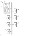
図7は、本実施の形態にかかるリッチモードによる楽音の消音処理(ステップ308)の例を示すフローチャートである。図7に示すように、CPU11は、離鍵された鍵が発音キーに該当するか否かを判断する(ステップ701)。ステップ701でYesと判断された場合に、CPU11は、離鍵された発音キーについての楽音信号データ、および、その効果キーについての楽音信号データに対して、消音を指示する情報を含む制御情報を音源部21に出力する。音源部21は、受け入れた情報に基づいて消音処理を行う(ステップ702)。
FIG. 7 is a flowchart showing an example of the musical sound muting process (step 308) in the rich mode according to the present embodiment. As shown in FIG. 7, the
図8は、発音キーのオンにより発音される楽音信号データのエンベロープおよび効果キーのオンにより発音される楽音信号データのエンベロープの例を示す図である。 FIG. 8 is a diagram showing an example of an envelope of musical sound signal data that is generated when the sound generation key is turned on and an envelope of musical sound signal data that is generated when the effect key is turned on.
図8に示すように、発音キーがオン状態になるのにともなって、一定のエンベロープで、所定の音色の楽音信号データが生成される(符号800参照)。その後に、効果キーがオンされると、上記所定の音色に関連付けられた演奏操作音を示す楽音信号データが生成される(符号810参照)。この楽音信号データのアタックレート(符号811)は、前述したように、発音キーの押鍵速度と効果キーの押鍵速度との差異により決定される。この演奏操作音の楽音信号データのベロシティは、発音キーに基づく楽音信号データのベロシティの半分であるため、図8において、効果キーのエンベロープの最高レベルV2は、V1/2である。 As shown in FIG. 8, as the sound generation key is turned on, musical tone signal data of a predetermined tone color is generated with a constant envelope (see reference numeral 800). Thereafter, when the effect key is turned on, musical tone signal data indicating the performance operation sound associated with the predetermined tone color is generated (see reference numeral 810). The attack rate (symbol 811) of the tone signal data is determined by the difference between the key-pressing speed of the sounding key and the key-pressing speed of the effect key, as described above. Since the velocity of the musical tone signal data of the performance operation sound is half of the velocity of the musical tone signal data based on the tone generation key, the maximum level V2 of the effect key envelope is V1 / 2 in FIG.
また、図8に示すように、発音キーのキーオフにともなって、発音キーについての楽音信号データ800および効果キーについての楽音信号データ810双方の消音処理が実行される。
In addition, as shown in FIG. 8, when the sound generation key is turned off, both the
本実施の形態によれば、第1の鍵が押鍵された時点から所定の時間内でかつ、当該押鍵されている第1の鍵を基準に前記鍵盤上の所定の範囲内に位置する第2の鍵が押鍵された場合に、CPU11は,第2の鍵を効果キーとして、演奏操作音に相当する第2の波形データを選択する情報を含む制御情報を生成して、音源部21に与える。これにより、音源部21は、効果キーについての楽音信号データを生成する。この結果、発音キーについての楽音信号データに、効果キーについての楽音信号データを付加することができる。
According to the present embodiment, the key is located within a predetermined range on the keyboard within a predetermined time from the time when the first key is pressed and with the first key being pressed as a reference. When the second key is pressed, the
また、本実施の形態においては、CPU11は、発音キーについての押鍵速度と、効果キーについての押鍵速度との速度差に基づいて、効果キーについての楽音信号データにおけるアタックレートが制御される。これによって、発音キーの押鍵速度を考慮して、効果キーをある速度で押鍵することで、所望のアタックレートの効果キーについての楽音信号データを生成することができる。
Further, in the present embodiment, the
たとえば、CPU11は、効果キーの押鍵速度が、発音キーの押鍵速度より大きくなるのにしたがって、効果キーについての楽音信号データのアタックレートが大きくなるように制御する。これにより、演奏者は効果キーの押鍵速度を調整することで、楽音信号のアタックレートを自由にコントロールすることができるようなる。この結果、発生される楽音に対して演奏者の意図する音楽表現を付加することが可能となる。
For example, the
また、本実施の形態において、CPU11は、発音キーが離鍵されたときに、発音キーについての楽音信号データおよび効果キーについての楽音信号データの双方の消音を指示する。これにより、演奏者は、消音については発音キーの操作のみを意識すれば足りる。
Further, in the present embodiment, when the sound generation key is released, the
なお、上記実施の形態においては、離鍵された鍵が発音キーに該当するときに、発音キーについての楽音信号データおよび効果キーについての楽音信号データ双方の消音処理が実行されている。しかしながら、離鍵されたキーが効果キーである場合に、効果キーについての楽音信号データのみに消音処理を施しても良い。 In the above-described embodiment, when the released key corresponds to the sounding key, both the sound signal data for the sounding key and the sound signal data for the effect key are silenced. However, when the released key is an effect key, the mute process may be performed only on the tone signal data for the effect key.
図9は、本実施の形態にかかるリッチモードによる楽音の消音処理(ステップ308)の他の例を示すフローチャートである。 FIG. 9 is a flowchart showing another example of the sound muting process (step 308) in the rich mode according to the present embodiment.
図9に示すように、この例では、CPU11は、離鍵された鍵が発音キーに該当するか否かを判断する(ステップ701)。ステップ701でYesと判断された場合に、CPU11は、離鍵された発音キーについての楽音信号データについて、その消音を指示する情報を含む制御情報を生成して、音源部21に出力する(ステップ902)。また、効果キーについての楽音信号データに消音処理が実行されていない場合(ステップ903でNo)には、CPU11は、この効果キーについての楽音信号データに対して、その消音を指示する情報を含む制御情報を音源部21に出力する(ステップ905)。
As shown in FIG. 9, in this example, the
また、ステップ901でNoであった場合でも、離鍵された鍵が効果キーであれば(ステップ904でYes)、CPU11は、当該効果キーについての楽音信号データに対して、消音を指示する情報を含む制御情報を音源部21に出力する(ステップ905)。これにより、図10に示すように、発音キーがオン状態のまま効果キーがオフされると、効果キーについての楽音信号データ1010の消音処理が実行される。その後、発音キーがオフされると、発音キーについての楽音信号データ1000の消音処理が実行される。
Even if No is determined in
また、上記実施の形態において、発音キーの押鍵速度V1と、効果キーの押鍵速度V2との差異ΔV(=V1−V2)に基づいて、アタックレートが直接決定されたが、これに限定されず、上記差異ΔVによって発音キーの楽音信号データのアタックレートに対する重みWが得られるようにしても良い。 In the above embodiment, the attack rate is directly determined based on the difference ΔV (= V1−V2) between the key press speed V1 of the sound generation key and the key press speed V2 of the effect key. However, the present invention is not limited to this. Instead, the weight W for the attack rate of the tone signal data of the tone generation key may be obtained by the difference ΔV.
図6(b)は、このアタックレートに対する重みWを算出するテーブルの例を示す図である。この図6(b)では縦軸は重みを示している。重みは、発音キーについての楽音信号データのアタックレートに乗算され、乗算結果が効果キーによる楽音信号データのアタックレートとされる。 FIG. 6B is a diagram illustrating an example of a table for calculating the weight W for the attack rate. In FIG. 6B, the vertical axis represents the weight. The weight is multiplied by the attack rate of the tone signal data for the tone generation key, and the multiplication result is used as the attack rate of the tone signal data by the effect key.
図6(b)の例では、ΔVがゼロ、つまり、発音キーの押鍵速度と効果キーの押鍵速度が同一であったときに、重みは1であり、発音キーの楽音信号データと効果キーの楽音信号データのアタックレートは同一となる。そしてΔVが大きくなるのにしたがって、アタックレートは重みの大きさに従って増大する。 In the example of FIG. 6B, when ΔV is zero, that is, when the key-pressing speed of the sounding key and the key-pressing speed of the effect key are the same, the weight is 1, and the tone signal data and the effect of the sounding key The attack rate of the key tone signal data is the same. As ΔV increases, the attack rate increases according to the weight.
次に、本発明の第2の実施の形態について説明する。第2の実施の形態においては、ΔVに、さらに発音キーの押鍵時刻と効果キーの押鍵時刻の時間差を考慮した重みが与えられ、重み付けされたΔV’に基づいて、効果キーによる楽音信号データのアタックレートが決定される。 Next, a second embodiment of the present invention will be described. In the second embodiment, ΔV is further given a weight in consideration of the time difference between the keying time of the sounding key and the keying time of the effect key. Based on the weighted ΔV ′, the musical tone signal by the effect key is given. The data attack rate is determined.
図11は、第2の実施の形態にかかるリッチモードによる楽音信号生成処理の例を示すフローチャートである。図11においてステップ1101〜ステップ1104は、図4のステップ401〜404と同様であるため説明を省略する。
FIG. 11 is a flowchart illustrating an example of a tone signal generation process in the rich mode according to the second embodiment. 11,
次いで、CPU11は、発音キーの押鍵時刻t1と、効果キーの押鍵時刻t2を参照して、その押鍵時刻の時間差Δt=t2−t1を算出し、発音キーに関する楽音に付加すべき効果音の楽音信号データのアタックレートを決定するためのΔV’を以下のように算出する。CPU11は、押鍵速度の差異ΔVおよび時間差Δtに基づいて、重み付きの速度の差異ΔV’=ΔV*(T/Δt)を算出する(ステップ1105)。なお、Tは所定の定数である。
Next, the
次いで、CPU11は、重み付きの差異ΔV’を用いて、図6(a)や図6(b)に示すテーブルを参照してアタックレートや、アタックレートに乗算する重みを得る。
Next, using the weighted difference ΔV ′, the
第2の実施の形態では、ΔVに対してT/Δtという重みが与えられるため、発音キーの押鍵時刻と効果キーの押鍵時刻との時間差が小さいほど、ΔV’は大きくなるため、効果キーの押鍵に伴って発音される楽音信号データのアタックレートは大きくなる。 In the second embodiment, since a weight of T / Δt is given to ΔV, ΔV ′ increases as the time difference between the key press time of the sounding key and the key press of the effect key increases. The attack rate of the musical tone signal data that is generated as the key is depressed increases.
ここでΔtを重みに用いた理由を説明する。一般的に、人間の心が高揚してきた場合は鍵盤を押す力だけでなく、押す間隔は短くなりがちである。これは鍵盤だけに限らず、テンポや拍のとり方なども同様である。したがって、鍵盤を押す力が増大、あるいは押鍵間隔が短くなった場合は、演奏者の心が高揚していると判断し、音色をよりヒステリックにしたほうが、演奏者の思考を忠実に表現できるものと思われる。この理由から第2の実施の形態では、演奏者の心の高揚と関係が深いΔtを用いて効果音を制御しているのである。 Here, the reason why Δt is used as the weight will be described. In general, when the human mind is elevated, not only the pressing force of the keyboard but also the pressing interval tends to be shortened. This is not limited to the keyboard, but the tempo and how to take beats are the same. Therefore, if the pressing force on the keyboard increases or the interval between key presses becomes shorter, it is judged that the performer's heart is uplifted, and the player's thoughts can be expressed more faithfully by making the tone more hysterical. It seems to be. For this reason, in the second embodiment, the sound effect is controlled using Δt, which is closely related to the enhancement of the performer's heart.
なお、ベロシティは第1の実施の形態と同様に、発音キーの押鍵速度に基づくベロシティの1/2とすれば良い。 As in the first embodiment, the velocity may be ½ of the velocity based on the key press speed of the sounding key.
ステップ1107およびステップ1108は、図4のステップ406および407と同様であり、音源部21はCPU11により生成された制御情報に基づく効果音の楽音信号データを生成する。
第2の実施の形態によれば、制御手段が、発音キーの押鍵時刻と、効果キーの押鍵時刻との時間差に基づいて、速度差ΔVを補正して、当該補正された速度差ΔV’に基づいて、効果キーについての楽音信号データにおけるアタックレートを制御する。これにより、押鍵速度だけではなく、効果キーの押鍵時刻をも考慮して効果キーについての楽音信号データのアタックレートを決定できるため、より演奏者による表現を反映した楽音信号データを生成することが可能となる。 According to the second embodiment, the control unit corrects the speed difference ΔV based on the time difference between the key press time of the sounding key and the key press of the effect key, and the corrected speed difference ΔV. Based on ', the attack rate in the musical tone signal data for the effect key is controlled. As a result, it is possible to determine the attack rate of the tone signal data for the effect key in consideration of not only the key press speed but also the key press time of the effect key, so that the tone signal data more reflecting the expression by the player is generated. It becomes possible.
次に、本発明の第3の実施の形態について説明する。第3の実施の形態においては、ギター演奏において多用されるビブラート奏法の音楽表現をより忠実に付加しようとするものである。ここでは発音キーおよび効果キーがオンされた状態でかつ、この発音キーがオンされた時点から一定範囲内に位置する他の第3鍵が一定時間内にオンされたときに、この鍵のオンに伴って、発音されている楽音信号データに対してビブラート奏法の音楽表現を与えるように構成している。第3の実施の形態においては、この第3の鍵を、第2の効果キーと称する。 Next, a third embodiment of the present invention will be described. In the third embodiment, the musical expression of the vibrato performance method frequently used in guitar performance is to be added more faithfully. Here, the key is turned on when the sounding key and the effect key are turned on, and when another third key located within a certain range from the time when the sounding key is turned on is turned on within a certain time. Accordingly, a musical expression of vibrato performance is given to the musical tone signal data being generated. In the third embodiment, this third key is referred to as a second effect key.
図12は、第3の実施の形態にかかるリッチモードによる楽音信号生成処理の例を示すフローチャートである。なお、第3の実施の形態において、CPU11は、図4に示す処理を実行し、ステップ403でNoと判断された場合に、処理を終了せずに、図12に示す処理に移行する。したがって、発音キーについての楽音信号データの生成(図4のステップ401、402)および効果キーについての楽音信号データの生成(ステップ403〜407)は、第1の実施の形態と同様である。
FIG. 12 is a flowchart illustrating an example of a musical sound signal generation process in the rich mode according to the third embodiment. In the third embodiment, the
ステップ403でNoと判断された場合には、CPU11は、押鍵された第3の鍵が第2の効果キーに該当するか否かを判断する(ステップ1201)。たとえば、発音キーの音高から上下1オクターブ以内の鍵が、発音キーの押鍵時刻から所定の時刻t2以内にオンされていれば、その鍵は第2の効果キーであると判断される。なお第2の効果キー(第3の鍵)のオンは1回とは限られず、複数回にわたって第2の効果キーのオンが生じ得る。
When it is determined No in
ステップ1201でYesと判断された場合には、CPU11は、今回オンされた第2の効果キーの押鍵時刻と、前回に押鍵されたキー(効果キー或いは第2の効果キー)の押鍵時刻との時間差Δt(n)を算出する(ステップ1202)。この時間差t(n)はRAM13に格納される。次いで、CPU11は、RAM13に格納された、前回の時間差t(n−1)を読み出して、時間差の差分dΔt=Δt(n)−Δt(n−1)を算出する(ステップ1203)。このように第2効果キーに対応する鍵を次々と押していくと、このdΔtが次々と変化する。
If it is determined Yes in
この変化は、例えばギターの押弦している部分をフレット上で揺らせるビブラートとよばれる演奏のピッチの揺れの周期と関連付けられる。このため、dΔtを、ビブラートやモジュレーションの時間的ゆれとして使用すれば、演奏する人間の心理を表現した音色の制御が可能となる。 This change is associated with, for example, a period of pitch fluctuation of a performance called vibrato that rocks a stringed portion of a guitar on a fret. For this reason, if dΔt is used as a temporal fluctuation of vibrato or modulation, it becomes possible to control a timbre that expresses the psychology of a human performing.
さらに、CPU11は、今回オンされた第2の効果キーの押鍵速度に基づいてベロシティV(n)を算出する(ステップ1204)。ステップ1204で算出されたベロシティV(n)もRAM13に格納される。CPU11は、RAMに格納された、前回のベロシティV(n−1)を読み出して、ベロシティの差分dVel=V(n)−V(n−1)を算出する(ステップ1205)。
Further, the
その後、CPU11は、時間差の差分dΔtに基づいて、発音キーに基づく楽音信号データおよび効果キーに基づく楽音信号データの双方のビブラートを制御するビブラート制御情報を生成する(ステップ1206)とともに、発音キーについての楽音信号データおよび効果キーについての楽音信号データの音量レベルを制御する音量レベル制御情報を生成する(ステップ1207)。
Thereafter, the
たとえば、ステップ1206において、CPU11は、時間差の差分dΔtと、ビブラートのピッチ変化量とを対応付けたピッチ変化量テーブルを参照して、ピッチ変化量を取得し、また、差分dΔtとビブラートにおける速度(モジュレーションのレート)とを対応付けたモジュレーションテーブルを参照して、モジュレーションのレートを取得する。CPU11は、これらをビブラート制御情報として、音源部21に出力する。音源部21は、ビブラート制御情報に基づいて、発音キーについての楽音信号データおよび効果キーについての楽音信号データを、ピッチ変化量にしたがってその音高の幅を変化させ、また、ジュレーションのレートにしたがって、その音高変化における速度を変化させる。
For example, in
図13(a)は、ピッチ変化量テーブルの一例を示す図、図13(b)は、モジュレーションテーブルの例を示す図である。これらテーブルはROM12に格納される。図13(a)に示すように、差分dΔtが大きくなるのにしたがって、ピッチの変化量が小さくなる。また、差分dΔtが大きくなるのにしたがって、モジュレーションのレートも小さくなる。すなわち、今回の時間差が、前回の時間差より大きくなれば大きくなるほど、つまり、第2の効果キーがオンされるタイミングが遅くなれば遅くなるほど、ビブラートのピッチ変化量およびモジュレーションのレートが小さくなり、楽音におけるビブラートの効果が小さくなる。
FIG. 13A shows an example of the pitch change amount table, and FIG. 13B shows an example of the modulation table. These tables are stored in the
また、ステップ1207において、CPU11は、ベロシティの差分dVelと、音量レベルの変化量とを対応付けた音量レベル変化量テーブルを参照して、音量レベルの変化量を取得し、音量レベル制御情報として、音源部21に出力する。音源部21は、音量レベル制御情報に基づいて、発音キーについての楽音信号データおよび効果キーについての楽音信号データの音量レベルを変化させる。
In
図14は、音量レベル変化量テーブルの例を示す図である。図14に示すように、ベロシティの差分dVelが大きくなるのにしたがって、音量レベル変化量は大きくなる。つまり、第2の効果キーの押鍵速度が速ければそれだけ発音されている楽音信号データ(発音キーに基づく楽音信号データおよび効果キーに基づく楽音信号データ)の音量が大きくなる。 FIG. 14 is a diagram illustrating an example of a volume level change amount table. As shown in FIG. 14, the volume level change amount increases as the velocity difference dVel increases. That is, the volume of the musical sound signal data (musical sound signal data based on the sounding key and musical sound signal data based on the effect key) that is sounded increases as the key-pressing speed of the second effect key increases.
なお、第3の実施の形態においては、時間差の差分dΔtに基づいて、ビブラートのためのピッチ変化量およびモジュレーションレートが制御されたが、これに限定されず、時間差の差分dΔtに基づいて、CPU11は、ピッチベンドのピッチ変化量を算出し、これを制御情報として音源部21に出力しても良い。この場合に、音源部21は、制御情報に基づいて、発音している楽音信号データ(発音キーについての楽音信号データおよび効果キーについての楽音信号データ)の音高を、制御情報に含まれるピッチ変化量にしたがって変化させる。
In the third embodiment, the pitch change amount and the modulation rate for vibrato are controlled based on the time difference difference dΔt. However, the present invention is not limited to this, and the
図15は、ピッチ変化量テーブルの他の例を示す図である。この例では、差分dΔtが負の場合には、ピッチ変化量は正、つまり、音高が高くなり、かつ、差分dΔtが大きくなる(「0」に近づく)のにしたがって、ピッチの変化量が小さくなる。その一方、差分dΔtが正の場合には、ピッチ変化量は負、つまり、音高は低くなり、かつ、差分dΔtが大きくなるのにしたがって、ピッチ変化量は大きくなる。 FIG. 15 is a diagram illustrating another example of the pitch change amount table. In this example, when the difference dΔt is negative, the pitch change amount is positive, that is, the pitch change amount increases as the pitch increases and the difference dΔt increases (closes to “0”). Get smaller. On the other hand, when the difference dΔt is positive, the pitch change amount is negative, that is, the pitch decreases, and the pitch change amount increases as the difference dΔt increases.
第3の実施の形態によれば、CPU11は、発音キーおよび効果キーが押された後に、所定の第2の時間内に所定の第2の範囲に位置する第3の鍵が押鍵された場合に、当該第3の鍵を第2の効果キーとして、発音キーについての楽音信号データおよび効果キーについての楽音信号データを変化させる制御情報を生成する。これによって、発音キーについての楽音信号データおよび効果キーについての楽音信号データが変化する。したがって、新たに3つ目以降の鍵を押鍵することで、発音中の楽音信号データにさらに変化を加えることができ、演奏者によるさらに豊富な表現を実現することができる。
According to the third embodiment, after the sound generation key and the effect key are pressed, the
第3の実施の形態においては、第2の効果キーの押鍵時刻と、その一つ前に押鍵された他の鍵の押鍵時刻との間の第1の時間差、および、上記他の鍵の押鍵時刻と、さらに一つ前に押鍵された鍵の押鍵時刻との間の第2の時間差との差分を算出し、この差分に基づいて、発音キーについての楽音信号データおよび効果キーについての楽音信号データにおけるビブラートを制御する。したがって、第2の効果キーの押鍵時刻を調整することで、演奏者は発音中の楽音に付加されるビブラートによる音楽表現を自由にコントロールすることが可能となる。 In the third embodiment, the first time difference between the key press time of the second effect key and the key press time of the other key that was pressed immediately before, and the other A difference between a key pressing time and a second time difference between the key pressing time of the key pressed one more time before is calculated, and on the basis of this difference, musical tone signal data for the sounding key and Controls vibrato in tone signal data for effect keys. Therefore, by adjusting the time at which the second effect key is pressed, the performer can freely control the musical expression by vibrato that is added to the musical tone being sounded.
また、第3の実施の形態においては、第2の効果キーの押鍵速度から得られるベロシティと、その一つ前に押鍵された鍵の押鍵速度から得られるベロシティとの間の差分を算出し、その差分に基づいて、発音キーについての楽音信号データおよび効果キーについての楽音信号データの音量レベルを調整する。したがって、3つ目以降の鍵の押鍵速度を調整することにより、演奏者の意図する音量レベルで楽音を発生させることが可能となる。 In the third embodiment, the difference between the velocity obtained from the key pressing speed of the second effect key and the velocity obtained from the key pressing speed of the key that was previously pressed is calculated. The volume level of the musical tone signal data for the tone generation key and the musical tone signal data for the effect key is adjusted based on the calculated difference. Therefore, by adjusting the key pressing speed of the third and subsequent keys, it becomes possible to generate a musical sound at a volume level intended by the performer.
本発明は、以上の実施の形態に限定されることなく、特許請求の範囲に記載された発明の範囲内で、種々の変更が可能であり、それらも本発明の範囲内に包含されるものであることは言うまでもない。 The present invention is not limited to the above embodiments, and various modifications can be made within the scope of the invention described in the claims, and these are also included in the scope of the present invention. Needless to say.
前記実施の形態において、効果キーについての楽音信号データは、発音キーの音高と同一の音高であるが、これに限定されるものではなく、発音キーの音高を基音周波数とした場合の高次倍音周波数とすることにより、発音キーの押鍵により発生される楽音の共鳴音信号を、効果キーの押鍵により生成するようにしてもよい。 In the above-described embodiment, the musical tone signal data for the effect key has the same pitch as the pitch of the sounding key, but is not limited to this, and the pitch of the sounding key is used as the fundamental frequency. By setting the higher harmonic frequency, the resonance signal of the musical sound generated by pressing the sounding key may be generated by pressing the effect key.
また、前記実施の形態において、効果キーについての楽音信号データのベロシティは、発音キーについての楽音信号データのベロシティの1/2としているがこれに限定されるものではなく、たとえば、双方のベロシティは同一であっても良い。 In the above embodiment, the velocity of the tone signal data for the effect key is ½ of the velocity of the tone signal data for the sound key, but is not limited to this. For example, the velocity of both is It may be the same.
10 電子楽器
11 CPU
12 ROM
13 RAM
14 サウンドシステム
15 表示部
17 鍵盤
18 操作部
21 音源部
22 オーディオ回路
23 スピーカ
10 Electronic
12 ROM
13 RAM
14
Claims (8)
前記鍵盤の各鍵に対して、当該鍵の押下にともなって順次オンする複数のスイッチを設けるとともに、前記複数のスイッチ夫々のオン時刻の時間差に基づいて押鍵速度を検出する押鍵速度検出手段と、
音色毎に、当該音色の楽音を表わす第1の波形データ、及び前記第1の波形データによって表される楽音に関連付けられた効果音を表わす第2の波形データを記憶する波形データ記憶手段と、
前記鍵盤のいずれの鍵も押鍵されていない状態において第1の鍵が押鍵された場合に、当該押鍵された鍵に割当てられた音高で前記波形データ記憶手段に記憶された指定された音色の第1の波形データを読み出して第1のエンベロープを付加することにより、第1の楽音信号データを生成する第1の楽音信号データ生成手段と、
前記第1の鍵が押鍵された時点から所定の時間内でかつ、当該押鍵されている第1の鍵を基準に前記鍵盤上の所定の範囲内に位置する第2の鍵が押鍵された場合に、前記第1の鍵に割当てられた音高に関連する音高で前記波形データ記憶手段から前記第1の波形データに対応する第2の波形データを読み出して第2のエンベロープを付加することにより、第2の楽音信号データを生成する第2の楽音信号データ生成手段と、
前記押鍵速度検出手段により、前記第1の鍵の押鍵に伴って検出された第1の押鍵速度と前記第2の鍵の押鍵に伴って検出された第2の押鍵速度との速度差を算出し、当該算出された速度差に基づいて前記第2の波形データに付加される第2のエンベロープを制御するエンベロープ制御手段と、
を有する電子楽器。 A keyboard having a plurality of keys;
For each key of the keyboard, a plurality of switches that are sequentially turned on as the keys are pressed are provided, and a key pressing speed detecting unit that detects a key pressing speed based on a time difference between the ON times of the plurality of switches. When,
Waveform data storage means for storing, for each tone color, first waveform data representing a tone of the tone and second waveform data representing a sound effect associated with the tone represented by the first waveform data ;
When the first key is pressed in a state where none of the keys on the keyboard is pressed, the designated pitch stored in the waveform data storage means is assigned to the pitch assigned to the pressed key. First musical tone signal data generating means for generating first musical tone signal data by reading out the first waveform data of the selected timbre and adding a first envelope;
The second key located within a predetermined range on the keyboard within a predetermined time from the time when the first key is pressed and within the predetermined range on the basis of the pressed first key The second waveform data corresponding to the first waveform data is read from the waveform data storage means at the pitch associated with the pitch assigned to the first key, and the second envelope is obtained. A second musical tone signal data generating means for generating second musical tone signal data by adding,
A first key pressing speed detected with the key pressing of the first key and a second key pressing speed detected with the key pressing of the second key by the key pressing speed detecting means; An envelope control means for controlling a second envelope added to the second waveform data based on the calculated speed difference;
Electronic musical instrument with
前記制御手段が、前記第3の鍵の押鍵タイミングと前記第2の鍵の押鍵タイミングとの間の第1のタイミング差、及び前記第2の鍵の押鍵タイミングと前記第1の鍵の押鍵タイミングとの間の第2のタイミング差を算出し、当該第1及び第2のタイミング差の差分に基づいて、前記ビブラート付与手段にて前記第1及び第2の楽音信号データに付与されるビブラートを制御するビブラート制御手段を有する請求項5に記載の電子楽器。 The electronic musical instrument further includes vibrato imparting means for imparting vibrato to the first and second musical tone signal data,
The control means includes a first timing difference between a key pressing timing of the third key and a key pressing timing of the second key, and a key pressing timing of the second key and the first key. And calculating the second timing difference between the first and second musical tone signal data based on the difference between the first timing difference and the second timing difference. 6. The electronic musical instrument according to claim 5, further comprising vibrato control means for controlling vibrato to be performed.
前記鍵盤のいずれの鍵も押鍵されていない状態において第1の鍵が押鍵された場合に、当該押鍵された鍵に割当てられた音高で前記波形データ記憶手段に記憶された指定された音色の第1の波形データを読み出して第1のエンベロープを付加することにより、第1の楽音信号データを生成する第1の楽音信号データ生成ステップと、
前記第1の鍵が押鍵された時点から所定の時間内でかつ、当該押鍵されている第1の鍵を基準に前記鍵盤上の所定の範囲内に位置する第2の鍵が押鍵された場合に、前記第1の鍵に割当てられた音高に関連する音高で前記波形データ記憶手段から前記第1の波形データに対応する第2の波形データを読み出して第2のエンベロープを付加することにより、第2の楽音信号データを生成する第2の楽音信号データ生成ステップと、
前記押鍵速度検出手段により、前記第1の鍵の押鍵に伴って検出された第1の押鍵速度と前記第2の鍵の押鍵に伴って検出された第2の押鍵速度との速度差を算出し、当該算出された速度差に基づいて前記第2の波形データに付加される第2のエンベロープを制御するエンベロープ制御ステップと、
を実行させるプログラム。 A keyboard having a plurality of keys, and a plurality of switches that are sequentially turned on as each key of the keyboard is pressed, and a key pressing speed based on a time difference between each of the plurality of switches. And a second waveform representing a sound effect associated with the musical tone represented by the first waveform data, and a first waveform data representing the musical tone of the timbre, and a second waveform representing a sound effect associated with the musical tone represented by the first waveform data. A computer applied to an electronic musical instrument having waveform data storage means for storing data;
When the first key is pressed in a state where none of the keys on the keyboard is pressed, the designated pitch stored in the waveform data storage means is assigned to the pitch assigned to the pressed key. A first musical tone signal data generating step of generating first musical tone signal data by reading out the first waveform data of the selected timbre and adding a first envelope;
The second key located within a predetermined range on the keyboard within a predetermined time from the time when the first key is pressed and within the predetermined range on the basis of the pressed first key The second waveform data corresponding to the first waveform data is read from the waveform data storage means at the pitch associated with the pitch assigned to the first key, and the second envelope is obtained. A second musical sound signal data generating step for generating second musical sound signal data by adding,
A first key pressing speed detected with the key pressing of the first key and a second key pressing speed detected with the key pressing of the second key by the key pressing speed detecting means; An envelope control step of controlling a second envelope added to the second waveform data based on the calculated speed difference;
A program that executes
Priority Applications (1)
| Application Number | Priority Date | Filing Date | Title |
|---|---|---|---|
| JP2008223023A JP5412766B2 (en) | 2008-09-01 | 2008-09-01 | Electronic musical instruments and programs |
Applications Claiming Priority (1)
| Application Number | Priority Date | Filing Date | Title |
|---|---|---|---|
| JP2008223023A JP5412766B2 (en) | 2008-09-01 | 2008-09-01 | Electronic musical instruments and programs |
Publications (3)
| Publication Number | Publication Date |
|---|---|
| JP2010060583A JP2010060583A (en) | 2010-03-18 |
| JP2010060583A5 JP2010060583A5 (en) | 2011-07-21 |
| JP5412766B2 true JP5412766B2 (en) | 2014-02-12 |
Family
ID=42187493
Family Applications (1)
| Application Number | Title | Priority Date | Filing Date |
|---|---|---|---|
| JP2008223023A Active JP5412766B2 (en) | 2008-09-01 | 2008-09-01 | Electronic musical instruments and programs |
Country Status (1)
| Country | Link |
|---|---|
| JP (1) | JP5412766B2 (en) |
Families Citing this family (1)
| Publication number | Priority date | Publication date | Assignee | Title |
|---|---|---|---|---|
| JP6610715B1 (en) * | 2018-06-21 | 2019-11-27 | カシオ計算機株式会社 | Electronic musical instrument, electronic musical instrument control method, and program |
Family Cites Families (5)
| Publication number | Priority date | Publication date | Assignee | Title |
|---|---|---|---|---|
| JP2508138B2 (en) * | 1987-10-02 | 1996-06-19 | ヤマハ株式会社 | Musical tone signal generator |
| JPH06332464A (en) * | 1993-05-21 | 1994-12-02 | Kawai Musical Instr Mfg Co Ltd | Electronic keyed musical instrument |
| JP2895349B2 (en) * | 1993-05-21 | 1999-05-24 | 株式会社河合楽器製作所 | Electronic keyboard instrument |
| JP3551569B2 (en) * | 1995-08-28 | 2004-08-11 | ヤマハ株式会社 | Automatic performance keyboard instrument |
| JP2000315082A (en) * | 1999-04-30 | 2000-11-14 | Kawai Musical Instr Mfg Co Ltd | Electronic keyboard instrument |
-
2008
- 2008-09-01 JP JP2008223023A patent/JP5412766B2/en active Active
Also Published As
| Publication number | Publication date |
|---|---|
| JP2010060583A (en) | 2010-03-18 |
Similar Documents
| Publication | Publication Date | Title |
|---|---|---|
| CN108630176B (en) | Electronic wind instrument, control method thereof, and recording medium | |
| JP4748011B2 (en) | Electronic keyboard instrument | |
| JP2004264501A (en) | Keyboard musical instrument | |
| JP2011158855A (en) | Automatic accompanying apparatus and automatic accompanying program | |
| CN111739495A (en) | Accompaniment control device, electronic musical instrument, control method, and recording medium | |
| JP5732982B2 (en) | Musical sound generation device and musical sound generation program | |
| JP5412766B2 (en) | Electronic musical instruments and programs | |
| JP6149890B2 (en) | Musical sound generation device and musical sound generation program | |
| JP2021081601A (en) | Musical sound information output device, musical sound generation device, musical sound information generation method, and program | |
| JP5742592B2 (en) | Musical sound generation device, musical sound generation program, and electronic musical instrument | |
| JP6410345B2 (en) | Sound preview apparatus and program | |
| JP5560574B2 (en) | Electronic musical instruments and automatic performance programs | |
| JP5827484B2 (en) | Music control device | |
| JP4520521B2 (en) | Electronic musical instrument tuning correction apparatus, electronic musical instrument tuning correction method, computer program, and recording medium | |
| JP5692275B2 (en) | Electronic musical instruments | |
| JP5453966B2 (en) | Musical sound generating device and musical sound generating program | |
| JP5151603B2 (en) | Electronic musical instruments | |
| JP6102975B2 (en) | Musical sound generation device, musical sound generation program, and electronic musical instrument | |
| JP7425558B2 (en) | Code detection device and code detection program | |
| KR100382079B1 (en) | Apparatus and control method for portable information terminal using music | |
| JP2010117419A (en) | Electronic musical instrument | |
| JP2009216769A (en) | Sound processing apparatus and program | |
| JP4253607B2 (en) | Electronic musical instrument tuning correction apparatus, electronic musical instrument tuning correction method, computer program, and recording medium | |
| JP6305275B2 (en) | Voice assist device and program for electronic musical instrument | |
| Hernández Canales | sin orejas |
Legal Events
| Date | Code | Title | Description |
|---|---|---|---|
| A521 | Written amendment |
Free format text: JAPANESE INTERMEDIATE CODE: A523 Effective date: 20110608 |
|
| A621 | Written request for application examination |
Free format text: JAPANESE INTERMEDIATE CODE: A621 Effective date: 20110608 |
|
| A131 | Notification of reasons for refusal |
Free format text: JAPANESE INTERMEDIATE CODE: A131 Effective date: 20130212 |
|
| A521 | Written amendment |
Free format text: JAPANESE INTERMEDIATE CODE: A523 Effective date: 20130404 |
|
| TRDD | Decision of grant or rejection written | ||
| A01 | Written decision to grant a patent or to grant a registration (utility model) |
Free format text: JAPANESE INTERMEDIATE CODE: A01 Effective date: 20131015 |
|
| A61 | First payment of annual fees (during grant procedure) |
Free format text: JAPANESE INTERMEDIATE CODE: A61 Effective date: 20131028 |
|
| R150 | Certificate of patent or registration of utility model |
Ref document number: 5412766 Country of ref document: JP Free format text: JAPANESE INTERMEDIATE CODE: R150 |